1
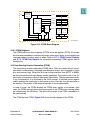
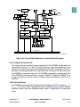
• When configured for OCB, OCAB, or OPWM modes, the state of the DASM
output flip-flop will remain unchanged.
• The state of the PWMSM output flip-flop will remain unchanged.
If the IMB FREEZE signal is asserted and FRZ = 0, the freeze condition is ignored, and
all CTM4 submodules will continue to operate normally.
10.4.3 LPSTOP Effect on the BIUSM
When the CPU32 LPSTOP instruction is executed, the system clock is stopped. All
dependent modules, including the CTM4, are shut down until low-power STOP mode
is exited.
10.4.4 BIUSM Registers
The BIUSM contains a module configuration register, a time base register, and a test
register. The BIUSM register block occupies the first four register locations in the
CTM4 register space. All unused bits and reserved address locations return zero when
read. Writes to unused bits and reserved address locations have no effect. Refer to
D.7.1 BIU Module Configuration Register, D.7.2 BIUSM Test Configuration Register, and D.7.3 BIUSM Time Base Register for information concerning BIUSM
register and bit descriptions.
10.5 Counter Prescaler Submodule (CPSM)
The counter prescaler submodule (CPSM) is a programmable divider system that provides the CTM4 counters with a choice of six clock signals (PCLK[1:6]) derived from
the main MCU system clock. Five of these frequencies are derived from a fixed divider
chain. The divide ratio of the last clock frequency is software selectable from a choice
of four divide ratios.
The CPSM is part of the BIUSM. Figure 10-2 shows a block diagram of the CPSM.
MC68336/376
USER’S MANUAL
CONFIGURABLE TIMER MODULE 4
Rev. 15 Oct 2000
MOTOROLA
10-4