1
Sample-Draw Transmitter
Instruction Manual
Part Number 71-0114
5May2010
© 2007 Thermo Fisher Scientific Inc. All rights reserved.
Specifications, terms and pricing are subject to change. Not all products are available in all countries. Please
consult your local sales representative for details.
Thermo Fisher Scientific
Air Quality Instruments
27 Forge Parkway
Franklin, MA 02038
1-508-520-0430
www.thermo.com/aqi
WEEE Compliance
This product is required to comply with the European Union’s Waste
Electrical & Electronic Equipment (WEEE) Directive 2002/96/EC. It is
marked with the following symbol:
Thermo Fisher Scientific has contracted with one or more
recycling/disposal companies in each EU Member State, and this product
should be disposed of or recycled through them. Further information on
Thermo Fisher Scientific’s compliance with these Directives, the recyclers
in your country, and information on Thermo Fisher Scientific products
which may assist the detection of substances subject to the RoHS Directive
are available at: www.thermo.com/WEEERoHS.
Thermo Fisher Scientific
WEEE Compliance
WARNING
THIS INSTRUMENT IS DESIGNED TO DETECT ONE OR MORE OF
THE FOLLOWING:
FLAMMABLE VAPORS, OXYGEN CONTENT, AND/OR TOXIC GAS AND TO
GIVE WARNING BEFORE THEY REACH HARMFUL CONDITIONS. IN ORDER
TO ENSURE THAT IT WILL WARN OF DANGEROUS CONCENTRATIONS, IT
IS ESSENTIAL THAT THE INSTRUCTIONS IN THIS MANUAL, PARTICULARLY
THOSE CONCERNING START UP , OPERATION , CALIBRATION , AND
MAINTENANCE, BE READ, UNDERSTOOD, AND FOLLOWED.
NOTATION CONVENTIONS
Notices are used in this operator's manual to alert you to hazardous conditions to person or instrument and to notify you of additional information.
This operator's manual uses the following notices.
WARNING
Notifies you of potential danger that can result in personal injury
or death.
CAUTION
Notifies you of potential damage to equipment.
NOTE
Notifies you of additional or critical information.
SERVICE LOCATIONS
For additional assistance, service is available from exclusive distributors worldwide.
Contact one of the phone numbers below for product support and technical information
or visit us on the web at www.thermo.com/aqi.
866-282-0430 Toll Free
508-520-0430 International
Warranty
Seller warrants that the Products will operate or perform substantially in
conformance with Seller's published specifications and be free from defects
in material and workmanship, when subjected to normal, proper and
intended usage by properly trained personnel, for the period of time set
forth in the product documentation, published specifications or package
inserts. If a period of time is not specified in Seller’s product
documentation, published specifications or package inserts, the warranty
period shall be one (1) year from the date of shipment to Buyer for
equipment and ninety (90) days for all other products (the "Warranty
Period"). Seller agrees during the Warranty Period, to repair or replace, at
Seller's option, defective Products so as to cause the same to operate in
substantial conformance with said published specifications; provided that
(a) Buyer shall promptly notify Seller in writing upon the discovery of any
defect, which notice shall include the product model and serial number (if
applicable) and details of the warranty claim; (b) after Seller’s review, Seller
will provide Buyer with service data and/or a Return Material
Authorization (“RMA”), which may include biohazard decontamination
procedures and other product-specific handling instructions; and (c) then,
if applicable, Buyer may return the defective Products to Seller with all
costs prepaid by Buyer. Replacement parts may be new or refurbished, at
the election of Seller. All replaced parts shall become the property of Seller.
Shipment to Buyer of repaired or replacement Products shall be made in
accordance with the Delivery provisions of the Seller’s Terms and
Conditions of Sale. Consumables, including but not limited to lamps,
fuses, batteries, bulbs and other such expendable items, are expressly
excluded from the warranty under this warranty.
Notwithstanding the foregoing, Products supplied by Seller that are
obtained by Seller from an original manufacturer or third party supplier are
not warranted by Seller, but Seller agrees to assign to Buyer any warranty
rights in such Product that Seller may have from the original manufacturer
or third party supplier, to the extent such assignment is allowed by such
original manufacturer or third party supplier.
In no event shall Seller have any obligation to make repairs, replacements
or corrections required, in whole or in part, as the result of (i) normal wear
and tear, (ii) accident, disaster or event of force majeure, (iii) misuse, fault
or negligence of or by Buyer, (iv) use of the Products in a manner for which
they were not designed, (v) causes external to the Products such as, but not
limited to, power failure or electrical power surges, (vi) improper storage
and handling of the Products or (vii) use of the Products in combination
with equipment or software not supplied by Seller. If Seller determines
that Products for which Buyer has requested warranty services are not
Thermo Fisher Scientific
Warranty
covered by the warranty hereunder, Buyer shall pay or reimburse Seller for
all costs of investigating and responding to such request at Seller's then
prevailing time and materials rates. If Seller provides repair services or
replacement parts that are not covered by the warranty provided in this
warranty, Buyer shall pay Seller therefor at Seller's then prevailing time and
materials rates. ANY INSTALLATION, MAINTENANCE, REPAIR,
SERVICE, RELOCATION OR ALTERATION TO OR OF, OR
OTHER TAMPERING WITH, THE PRODUCTS PERFORMED BY
ANY PERSON OR ENTITY OTHER THAN SELLER WITHOUT
SELLER'S PRIOR WRITTEN APPROVAL, OR ANY USE OF
REPLACEMENT PARTS NOT SUPPLIED BY SELLER, SHALL
IMMEDIATELY VOID AND CANCEL ALL WARRANTIES WITH
RESPECT TO THE AFFECTED PRODUCTS.
THE OBLIGATIONS CREATED BY THIS WARRANTY
STATEMENT TO REPAIR OR REPLACE A DEFECTIVE PRODUCT
SHALL BE THE SOLE REMEDY OF BUYER IN THE EVENT OF A
DEFECTIVE PRODUCT. EXCEPT AS EXPRESSLY PROVIDED IN
THIS WARRANTY STATEMENT, SELLER DISCLAIMS ALL
OTHER WARRANTIES, WHETHER EXPRESS OR IMPLIED, ORAL
OR WRITTEN, WITH RESPECT TO THE PRODUCTS,
INCLUDING WITHOUT LIMITATION ALL IMPLIED
WARRANTIES OF MERCHANTABILITY OR FITNESS FOR ANY
PARTICULAR PURPOSE. SELLER DOES NOT WARRANT THAT
THE PRODUCTS ARE ERROR-FREE OR WILL ACCOMPLISH
ANY PARTICULAR RESULT.
Warranty
Thermo Fisher Scientific
TABLE OF CONTENTS
Chapter 1
Introduction
Overview . . . . . . . . . . . . . . . . . . . . . . . . . . . . . . . . . . . . . . . . . . . . . . . . 1
Decription . . . . . . . . . . . . . . . . . . . . . . . . . . . . . . . . . . . . . . . . . . . . . . . 1
Target Gases. . . . . . . . . . . . . . . . . . . . . . . . . . . . . . . . . . . . . . . . . . . . . . 2
Specifications . . . . . . . . . . . . . . . . . . . . . . . . . . . . . . . . . . . . . . . . . . . . . 3
Chapter 2
Installation
Mounting the Transmitter . . . . . . . . . . . . . . . . . . . . . . . . . . . . . . . . . . . 5
Connecting the Sample Lines . . . . . . . . . . . . . . . . . . . . . . . . . . . . . . . . 6
Wiring the Transmitter. . . . . . . . . . . . . . . . . . . . . . . . . . . . . . . . . . . . . . 7
Chapter 3
Start Up & Operation
Preparing for Start Up . . . . . . . . . . . . . . . . . . . . . . . . . . . . . . . . . . . . . . 9
Setting the Channel Parameters at the Controller . . . . . . . . . . . . . . . . . 9
Setting the Fresh Air Signal . . . . . . . . . . . . . . . . . . . . . . . . . . . . . . . . . 10
Chapter 4
Calibration
Preparing for calibration . . . . . . . . . . . . . . . . . . . . . . . . . . . . . . . . . . . 12
Calibrating the Detector . . . . . . . . . . . . . . . . . . . . . . . . . . . . . . . . . . . . 12
Chapter 5
Maintenance
Preventive Maintenance . . . . . . . . . . . . . . . . . . . . . . . . . . . . . . . . . . . . 17
Troubleshooting . . . . . . . . . . . . . . . . . . . . . . . . . . . . . . . . . . . . . . . . . . 18
Replacing the Toxic or Oxygen Sensor . . . . . . . . . . . . . . . . . . . . . . . . 22
Replacing the Combustible Gas Sensor . . . . . . . . . . . . . . . . . . . . . . . . 23
Replacing the Toxic and Oxygen Amplifier . . . . . . . . . . . . . . . . . . . . 24
Replacing the Combustible Amplifier . . . . . . . . . . . . . . . . . . . . . . . . . 25
Replacing the Pump . . . . . . . . . . . . . . . . . . . . . . . . . . . . . . . . . . . . . . . 26
71-0114
ix
Sample Draw Operator’s Manual
Appendix A
Parts List . . . . . . . . . . . . . . . . . . . . . . . . . . . . . . . . . . . . . . . . . . . . . . . 29
Appendix B
External Wiring Instructions . . . . . . . . . . . . . . . . . . . . . . . . . . . . . . . . 33
Appendix C
Calibration Response Charts . . . . . . . . . . . . . . . . . . . . . . . . . . . . . . . . 37
x
71-0114
Chapter
1
INTRODUCTION
Overview
The Sample-Draw Transmitter is a series of oxygen, combustible gas, and
toxic gas transmitters.
Description
The Sample-Draw Transmitter assembly is comprised of a sample-drawing
apparatus, main board, gas sensor, a temperature compensation circuit, and an
amplifier/transmitter electronic assembly all enclosed in a weather and dust
resistant housing.
71-0114
1
Sample Draw Operator’s Manual
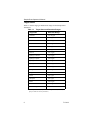
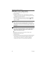
Target Gases
Table 1-1 lists the target gas and detection ranges for the Sample-Draw
Transmitter.
Table 1-1
1.
2
Target Gases and Detection Ranges
Target Gas
Detection Range
Ammonia
0 to 100 ppm
Arsine
0 to 1 ppm
Carbon Monoxide
0 to 500 ppm
Chlorine
0 to 10 ppm
Chlorine Dioxide
0 to 2 ppm
Diborane
0 to 1 ppm
Fluorine
0 to 10 ppm
Hydrogen Chloride
0 to 30 ppm
Hydrogen Cyanide
0 to 50 ppm
Hydrogen Fluoride
0 to 10 ppm
Hydrogen Sulfide
0 to 100 ppm
Nitric Oxide
0 to 100 ppm
Nitrogen Dioxide
0 to 20 ppm
Oxygen
0-30% vol
Ozone
0 to 1 ppm
Phosphine
0 to 1 ppm
Silane
0 to 20 ppm
Sulfur Dioxide
0 to 20 ppm
Combustible gases
0 to 100% LEL1
Lower Explosive Limit (may also be used in ranges of 0 to 5,000 or 10,000
parts per million for some hydrocarbons).
71-0114
Introduction
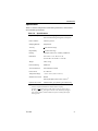
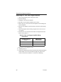
Specification
Table 1-2 lists the Sample-Draw Transmitter performance, electrical and
environmental specifications.
Table 1-2
Specifications
Amplifier Outputs
4 to 20 mA analog signal (to controller)
100 to 500 mV analog test signals (at test jacks)
Fault Condition
0 mA loop current
Sampling Method
Sample-Draw
Accuracy
+ 10% detection range
Repeatability
+ 5% detection range
Housing
Fiberglass (with Lexan1 window), NEMA 4X
Dimensions
10.0 in. H x 7.15 in. W x 4.5 in. D
(25.4 cm H x 18.2 cm W x 11.4 cm D)
Weight
4 lbs (1.8 kg)
Enclosure Rating
NEMA 4X
Area Classification
Non-hazardous locations
Power Source
12 to 24V DC
Temperature Range
- 4° F to 113° F (-20° C to 45° C)
Standard Accessories
Manual
In-line hydrophobic filter (some versions)2
Optional Accessories
Calibration kits, gas cylinders, gas collection bag
1.
Lexan is a registered trademark of General Electric Company.
2.
This filter is not furnished for use with reactive gases Cl2, ClO2, F2, HCl,
HF, NH3, NO2 and O3. These gases react with or are absorbed by entrapped
water or other residue, and thus would be lost prior to entering the sampledrawing system.
71-0114
3
Sample Draw Operator’s Manual
4
71-0114
Chapter
2
INSTALLATION
Mounting the Transmitter
WARNING
Perform all installation procedures in a fresh air environment
(known to be free of combustible and toxic gases and of normal
oxygen content). The transmitter is not in operation as a gas
monitoring system until the start-up procedure is complete.
CAUTION
The Sample-Draw Transmitter is not suitable for Class I hazardous
areas. Mount the Sample-Draw Transmitter in a non-hazardous
area
1. Select a mounting area that is indoors or sheltered from rain or snow.
Make sure there is enough room to mount the housing, open the
housing door, and to make wiring and sample line connections at the
bottom of the housing.
2. Secure the housing to the vertical surface using bolts or screws
through the mounting flanges (see Figures 2-1).
10.0"
[25.4 cm]
8.94"
[22.7 cm]
4.0"
[10.2 cm]
4.50"
[11.4 cm]
7.15"
[18.2 cm]
Figure 2-1 Outline and Mounting Dimensions
71-0114
5
Sample Draw Operator’s Manual
Connecting the Sample Lines
Refer to Figure 2-2 Flow Diagram and Figure 2-3 for Inlet and Outlet
connections.
Pump location
for HF and F2
Flow Switch
Flow
Block
Gas Sensor
Flowmeter
Exhaust
P
V
P
In
Out
Flow
Restrictor
Hydrophobic Filter
Not used on Cl2, Cl02, F2,
HCl, HF, NH3, NO2, and O3.
Flow
Adjust Valve
Out
In
Pump
(all gases except HF and F2)
Inlet
Figure 2-2 Flow Diagram
1. Attach 1/4 in. OD TEFLON® tubing to the inlet fitting. The other end
of the tubing should be at the monitoring location.
2. If supplied, insert the filter into the incoming sample line at a point
near the inlet fitting, of the sample-draw transmitter.
3. If necessary, connect a 1/4 in. OD plastic or stainless steel tube to the
EXHAUST fitting. Keep the exhaust tubing as short as possible.
Route the exhaust to an open area where the sample can safely
dissipate.
®DuPont registered trademark.
6
71-0114
Installation
Wiring the Transmitter
Use a three-conductor, shielded cable, or run the wiring within metal conduit
to reduce Radio Frequency Interference (RFI) and Electromagnetic
Interference (EMI).
Use 18 AWG wire or larger. The two-way wire and receiver resistance must
not exceed 200 ohms for 12 volts systems or 600 ohms for 24 volts systems.
WARNING
Make sure all power to the controller is turned off during all
wiring procedures.
•
The power circuit (“+12-24 volts” and “__”) supplies both the flow
system (pump and signal LEDs) and the signal loop circuit.
•
The signal loop circuit (amplifier/transmitter plus all external
components such as controller, displays, etc.) all of which share the
common 4-20 mA current loop, which begins at “+12-24 volts” and
terminates back at controller common "__".
WARNING
Do Not Overload the Transmitter Signal loop or signal limiting
due to excessive loop resistance could result in understatement of
hazardous conditions. From Ohm’s Law, a signal loop powered
from a 12 volt source cannot deliver more than 20 mA (full scale
reading) if the total loop resistance, including all wiring, this
transmitter (25 ohms internal), the receiver, and all other loop
device input circuits, exceed 600 ohms. Operation from 24 volts
permits about twice the loop resistance. Do not operate from
voltages below 12 volts.
CAUTION
Do not run transmitter and AC power wiring through the same
conduit.
1. Connect the sample-draw transmitter to the receiver, controller or
other 12-24 volt DC power source.
71-0114
7
Sample Draw Operator’s Manual
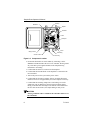
Main Board
DC Pump
Amplifier
Flow Meter
Cable
FlowAdjust
Sensor
Wiring Terminals
Outlet Fitting
Conduit 1/2" NPT
Inlet Fitting
Figure 2-3 Component Location
2. Ground the shield cable or metal conduit by connecting it to the
SHIELD or GND terminal at the receiver or controller. Do not ground
any of the three power/signal terminals in the sample drawing
transmitter to its housing.
3. Confirm that the detector is connected to the amplifier.
4. Confirm that the terminal block on the amplifier is connected to the
PC board cable.
5. Turn on the power to the system at the power source.
6. Confirm that the flowmeter “PILOT” light is on and the flowmeter
indicates a flow rate of approximately 0.6 SCFH. Adjust if necessary.
7. Confirm that the incoming sample line is not leaking. To test the
sample line, put you thumb over the end of the incoming sample
tubing. If the flowmeter ball drops to the bottom of the column and
the flow fail circuit activates, the sample tubing is ready to use.
CAUTION
Always ground the cable or conduit at the controller and never at
the transmitter.
8
71-0114
Chapter
3
START UP & OPERATION
Complete the following procedure to place the controller and the transmitter
into normal operation.
Preparing for Start Up
1. Complete the mounting and wiring procedures described in the
Installation chapter of this manual.
2. Connect incoming power to the controller as described in the receiver
or controller manual.
NOTE
Allow the sensor to stabilize for 1 hour after power is introduced
before calibrating.
Setting the Channel Parameters at the Controller
The sample drawing transmitter may be used with a wide variety of receivers
and controllers which provide 12 to 24 volts DC power at 400 mA and a
means of accepting and interpreting a 4-20 mA signal proportional to gas
concentration in the ranges shown in Table 1-1 of this manual
When you install the transmitter, set the parameters for that channel at the
controller. For instructions on setting the channel parameters at the
controller, see the receiver or controller manual.
71-0114
9
Sample Draw Operator’s Manual
Setting the Fresh Air Signal
WARNING
If you suspect the presence of target gas during the start-up
procedure, use the calibration kit described in the calibration
chapter and the zero-emission air cylinder to introduce fresh air to
the detector and confirm an accurate zero setting (span setting for
oxygen monitoring systems).
1. Confirm that the receiver, controller or DC power source are on.
2. Open the housing cover.
NOTE
Some controllers have a feature that enables you to disable the alarm
LEDs, buzzer, and relays during the calibration procedures, response
tests, and so on. Refer to the controller manual for information. Make
sure you re-enable full alarm functionality after the calibration
procedure is complete.
3. Confirm that the sample line inlet is sampling from a source of clean
air.
4. Select the millivolt (mV) range on the multimeter. Plug the positive
multimeter lead into the white (+) test jack: plug the negative lead
into the blue (-) test jack.
5. Confirm a reading of 100 mV (toxic/combustible) or 379 mV (oxygen)
on the multimeter. Adjust the potentiometer on the amplifier if
necessary.
• Toxic/combustible - Adjust “ZERO” pot until the multimeter reading
is 100 mV
• Oxygen - Adjust “SPAN” pot until the multimeter reading is 379 mV
6. Remove the multimeter leads from the test jacks, and secure the cover
to the housing.
The transmitter is now in operation.
10
71-0114
Chapter
4
CALIBRATION
This chapter describes the optional calibration kit used for calibrating the
transmitter. See Parts List, in Appendix A of this manual for ordering
information.
WARNING
Accurate calibration of the transmitter is essential to ensure
accurate readings of toxic gas concentrations. Incorrect
calibration can impair the performance of the transmitter and
place you in unnecessary danger if hazardous conditions exist.
The calibration kit contains all of the equipment you need to introduce a
calibration sample to the detector. It includes the following components:
• Storage Case (safely stores the components of the calibration kit).
• Cylinder (contains a known concentration of target gas).
• Regulator (controls the flow of the sample from the cylinder to the
detector)
• Tubing (connects components of the calibration kit).
• Gas collecting Bag (permits matching of regulator flow rate to the
sample pump flow rate). One of two types may be furnished:
– TEDLAR™ bag may be used for all gases.
– Vinyl bag is suitable for Nitrogen, hydrogen, propane, hexane and
carbon monoxide, or Zero Air.
• Pinch Clamp and Y fitting (controls gas flow between the gas
collecting bag and transmitter).
For calibration it is preferable to introduce the calibration gas directly to the
inlet of the sample line. If this is not practical, temporarily remove the
sample line tubing from the Inlet fitting of the sample-draw adapter, connect
a short piece of tubing in its place and admit the calibration gas there. Be
sure to replace the sample line when calibration is complete.
71-0114
11
Sample Draw Operator’s Manual
Preparing for Calibration
This section describes how to prepare the transmitter for calibration. The
procedure includes step-by-step instructions for preparing the calibration kit
and the transmitter.
WARNING
Calibrate the detector in a fresh air environment (environment
known to be free of toxic gases). If the in-line hydrophobic filter is
used during normal operation, calibrate the detector with the
filter in place.
Calibrating the Detector
This chapter describes how to prepare the gas cylinder, set the clean air base
line and gas response reading for the toxic gas and oxygen transmitters.
Calculating the Calibration Gas Response Reading
The 100 to 500 mV test signal at the test jack of the transmitter amplifier is
used to calibrate the transmitter. The following formula describes how to
calculate the output test signal as a function of the gas concentration:
Test signal = ((gas concentration/full scale range) x 400 mV) +(100 mV)
• For example, if you are using a gas cylinder of 5 ppm chlorine to
calibrate a transmitter whose full-scale range is 0-10 ppm:
((5 {ppm conc.}/10 {ppm full-scale conc.}) x 400 mV {range}) +
(100 mV {offset}).
= (5/10 x 400 mV) + (100 mV) = 300 mV gas signal setting on
multimeter.
• For oxygen, the measurement range is 0-30% by volume and the
recommended calibration gas is clean air, which contains 20.9%
oxygen, so the calculation is:
((20.9/30) x 400) + (100) = 378.7 (or 379) mV.
For user convenience, graphs of signal versus gas concentration are shown in
Appendix C of this manual for each gas range.
12
71-0114
Calibration
Preparing the Gas Cylinder
NOTE
When performing the following steps, use gas samples of known
concentration. Cylinders of known concentration are available from
Thermo Fisher Scientific (see Parts List in Appendix A). Specify gas and
concentration when ordering gas cylinders.
1. Verify the regulator flow control valve is closed, then carefully screw
the regulator onto the cylinder.
2. Verify that all tubing connections are tight and secure.
Polyurethane Tubing
Clamp
Vinyl Tubing
“Y” Connector
Flow Control
Knob
Gas Collecting Bag
Cylinder
Figure 4-1 Calibration Kit with Gas Cylinder and Gas Collecting
Bag
71-0114
13
Sample Draw Operator’s Manual
Calibrating the Toxic Gas or Combustible Detector
1. Verify the absence of toxic/combustible gas or any atmosphere other
than clean air at the calibration site, by ventilation with clean air or by
testing with a portable gas analyzer.
2. Open the housing.
3. Set the multimeter to 0-500 DC mV range. Plug the positive
multimeter lead into the white (+) test jack and the negative lead into
the blue (-) test jack of the amplifier.
4. Confirm that the multimeter shows a reading of 100 mV. If the
reading is other than 100 mV adjust the ZERO potentiometer on the
amplifier so that it does so. Leave the multimeter probes connected to
the test jacks for setting the toxic gas response.
NOTE
For Cl2, ClO2, F2, HF, NO2 and O3 transmitters, turn the zero control
counter-clockwise to increase reading, for all other gases turn it
clockwise to increase reading.
SETTING THE TOXIC OR COMBUSTIBLE GAS RESPONSE READING
1. Set the multimeter to 0-500 DC mV range. Plug the positive
multimeter lead into the white (+) test jack and the negative lead into
the blue (-) test jack.
2. Close the clamp, then open the flow control knob until the gas
collecting bag is approximately 3/4 full.
3. Open the clamp and allow the sample-draw pump to draw gas from
the gas collecting bag. Adjust the regulator so the gas collecting bag
remains 3/4 full.
4. After the reading stabilizes (normally 1 to 2 minutes), confirm a
reading of the SPAN pot on the amplifier until the multimeter reads
the value calculated at the beginning of this section or adjust the
SPAN potentiometer on the amplifier so that it does so.
CAUTION
If the reading on the multimeter has not stabilized after 2 minutes,
see the Troubleshooting section of this manual for slow response.
5. Remove the multimeter test probes and secure cover to housing.
6. Close the flow control knob and disconnect the calibration gas
cylinder. Flatten the gas collecting bag to expel any remaining gas.
The transmitter is now in normal operation.
14
71-0114
Calibration
Calibrating the Oxygen Detector
SETTING THE OXYGEN ZERO READING
1. Set the multimeter to 0-500 DC mV range. Plug the positive (+)
multimeter lead into the white (+) test jack and the negative lead into
the blue (-) test jack of the amplifier.
2. Attach the regulator to the cylinder of 100% nitrogen.
3. Connect the regulator output to the sample line inlet.
4. Observe the millivolt reading on the multimeter, which should decline
towards 100 mV as nitrogen enters the detector and displaces residual
air.
5. When the multimeter reading has stabilized, turn the “ZERO” pot on
amplifier until reading is 100 mV.
6. Leave the multimeter connected to the amplifier test jacks.
7. Close the flow control knob on the regulator and disconnect the
nitrogen cylinder. Flatten the gas collecting bag to expel any
remaining gas.
SETTING THE OXYGEN RESPONSE READING
For calibration of oxygen transmitters, the recommended calibration gas is
clean fresh air, if its purity can be assured by ventilation or by test with a
portable oxygen indicator. If this is impractical, a cylinder of certified ZERO
AIR should be used. For clean fresh air, the calibration setting should be 379
mV at the test jacks (equivalent to 15.1 mA in signal loop), to correspond
with the 20.9% oxygen present in clean air. For ZERO AIR, calculate the
proper span setting for the analyzed oxygen content (if other than 20.9%)
from the formula or from the chart in Appendix C of this manual, then
proceed as follows:
1. If using clean air for calibration, assure that the sample line inlet is
relocated to a source of air known to be free of contamination, then go
directly to step 5 (otherwise connect the regulator to a cylinder of
certified ZERO AIR.
NOTE
The ZERO AIR cylinder is not included in the standard calibration kit,
as clean air is most often readily available to the detector by normal
methods of ventilation. It may be ordered separately (81-0076) and
uses the same regulator (81-1003) as the nitrogen cylinder.
71-0114
15
Sample Draw Operator’s Manual
2. Attach the flow regulator to the cylinder of zero air and the Y fitting
of the gas collecting bag.
3. Close the clamp and then open the flow control valve until the gas
collecting bag if approximately 3/4 full.
4. Open the clamp and allow the sample-draw pump to draw gas from
the gas collecting bag. Adjust the flow regulator so the gas collecting
bag remains 3/4 full.
5. After the reading stabilizes (normally 1 to 2 minutes), confirm a
reading of 379 mV (or calculated value for cylinder oxygen content, if
different from 20.9%) on the multimeter. If necessary, adjust the
“SPAN” pot on the amplifier until the multimeter reads correctly.
6. Close the flow control knob and disconnect the ZERO AIR gas
cylinder. Flatten the gas collecting bag to expel any remaining gas. If
using the method of relocating sample line inlet, be sure too move the
sample line inlet back to the desired monitoring location.
The transmitter is now in normal operation.
16
71-0114
Chapter
5
MAINTENANCE
WARNING
Perform all maintenance activities in a non-hazardous environment.
Preventive Maintenance
This schedule describes daily, monthly, and quarterly procedures to ensure
the performance and durability of the transmitter.
Daily
1. Verify that the receiver indicates a reading near 0 ppm (toxic), 0%
LEL (combustible) or near 21% volume (oxygen). Investigate
significant changes in the display reading and signal output.
2. Confirm that the transmitter pilot light (above the flowmeter) is on.
3. Confirm that the flowmeter indicates a flow rate of approximately 0.6
SCFH. Adjust if necessary using the flow adjustment valve.
Monthly
NOTE
Some controllers have a feature that permits disabling of the alarm
devices during maintenance and calibration procedures. Refer to the
controller manual for information. Be sure to enable full alarm
functionality after the calibration or response test procedure is
complete.
To test any visual, audible and relay alarm indications by the
controller during the response test, use a concentration of gas greater
than the alarm setpoints.
If you have evacuation alarms or alarms that are forwarded to the fire
department, be sure to notify the appropriate people before you test
the alarms.
71-0114
17
Sample Draw Operator’s Manual
1. Confirm that the controller display reading is approximately 0 ppm
(toxic) and 21% (oxygen). If not, set the fresh air signal at the amplifier
to 100 mV (toxic) or 379 mV (oxygen), as described in the Start Up &
Operation chapter of this manual.
2. Assemble the calibration kit and introduce the gas to the detector as
described in the Calibration chapter of this manual.
3. After the reading stabilizes (normally 1 to 2 minutes), confirm that the
display reading for the controller responds to the gas sample as the
sample is introduced to the detector and is within ±10% of the desired
reading. If not, perform the calibration procedure as described in the
Calibration chapter of this manual.
4. Confirm that the receiver or controller alarm functions (if any)
respond appropriately.
5. Turn off the calibration gas. Disassemble and store the calibration kit
as described in the Calibration chapter of this manual.
Quarterly
CAUTION
Calibrate the transmitter at lease once every three months. Some
applications may require a more frequent calibration schedule.
Perform the calibration procedure as described in the Calibration chapter of
this manual.
Troubleshooting
The section describes symptoms, probable causes, and suggested responses
for problems you may encounter with the transmitter.
Fault Condition
Symptoms:
• FAULT or FAILURE indication.
• Negative reading at receiver or controller.
• Transmitter flow “FAIL” light is on.
• Transmitter flowmeter indicates less than 0.6 SCFH.
18
71-0114
Maintenance
Probable Causes:
• The power supply, controller, Sample-Draw Transmitter termination
PC board, amplifier or detector wiring connections are incorrect or
incomplete, see Chapter 2.
• Sample-Draw Transmitter ZERO potentiometer is adjusted incorrectly,
see Chapter 3.
• Low flow due to clogged filter, obstructed sample line, failed pump,
etc., see Chapter 3.
• Sensor is missing, improperly installed or defective.
• Amplifier improperly set or defective.
Suggested Response:
• Check all components for proper connection to power and continuity
of signal loop (see wiring diagram in Appendix B).
• Verify other components are properly connected and appear to be
operating normally, check the setup of the transmitter. A fault
problem can arise in either (or both) of two areas: the sample-draw
subsystem or the electronic subsystem.
CHECK THE SAMPLE-DRAW SUBSYSTEM AS FOLLOWS:
1. Check that the flowmeter indicates approximately 0.6 SCFH. If this
reading is low, attempt to set the correct rate using the flow adjust
valve. If you cannot set the correct rate using the flow adjust valve,
replace the filter in the sample line and check the sample line for
obstructions or kinks.
2. If you still cannot set the correct rate using the flow adjust valve,
replace the pump.
3. If the fault condition continues, contact Thermo Fisher Scientific for
further instructions.
CHECK THE ELECTRONIC SUBSYSTEM AS FOLLOWS:
1. Confirm that the wiring to the controller terminal strip, the main
board and the amplifier terminal block is complete and correct.
2. Confirm that the sensor cable is connected to the amplifier.
3. Confirm that the sensor is installed in the flow block.
4. Confirm that the sensor is plugged into the cable to the amplifier.
5. Set the fresh air signal as described in the Start Up & Operation
chapter of this manual.
71-0114
19
Sample Draw Operator’s Manual
IF THE CONDITION CONTINUES, FURTHER ISOLATE THE PROBLEM AS FOLLOWS:
1. Disconnect the transmitter wires at the controller terminal strip and
connect them to the terminals of a different channel or controller
known to be operating correctly. If the fault condition clears, the
controller terminal strip or main circuit board is bad. Contact Thermo
Fisher Scientific for further instructions. If the fault continues, go to
the next step.
2. Check the fresh air signal at the amplifier test jack as described in the
Start Up & Operation chapter of this manual. If you can set the fresh
air signal to 100 mV (toxic/combustible) or 379 mV (oxygen), then
the detector amplifier and sample-draw subsystem are operating
correctly. Contact Thermo Fisher Scientific for further instruction. If
the fault condition continues, go to the next step.
3. Disconnect the detector and connect a detector known to be operating
correctly. If the fault condition clears, replace the detector. You can
replace the plug-in sensor as an alternate to replacing the entire
detector assembly. If the fault condition continues, go to the next step.
4. Connect the detector in question to an amplifier known to be
operating correctly. If the fault clears, replace the amplifier.
5. If you replaced the amplifier or detector assembly, perform the
calibration procedure.
6. If the fault condition continues contact Thermo Fisher Scientific for
further instruction.
20
71-0114
Maintenance
Difficult or Unable to Calibrate, Slow or No Response
Symptoms:
• Unable to accurately calibrate the transmitter.
• Slow or no response to calibration gas during monthly response test.
• Transmitter requires frequent calibration.
NOTE
Under normal conditions, the transmitter requires calibration
approximately every 3 months. Some applications may require a
more frequent calibration schedule.
Probable Cause:
• Sample in gas cylinder is low, exhausted or out-dated.
• Sensor is outdated or is reaching the end of its useful life.
• Low flow due to clogged filter, obstructed sample line, failed pump, .
Suggested Response:
1. Make sure the calibration cylinder has an adequate supply of fresh gas.
2. Replace the plug-in sensor if it is outdated or shows signs of leakage
or liquid contamination (investigate for source of liquid, if present).
3. Check the in-line hydrophobic filter (if installed). If the filter is
installed, remove it. If the gas response changes after you remove the
filter, the filter is contaminated. Replace the filter.
NOTE
Filter is not recommended for reactive gases such as Chlorine,
Fluorine, etc.
4. Check the sample line for leaks by plugging the inlet to the sample
line and assuring that the flowmeter float ball drops to the bottom of
the flow column and that the flow “FAIL” light (above the flowmeter)
is lit. If not, find and correct the leak. Unplug the sample line inlet and
perform a calibration.
5. If calibration difficulties continue, contact Thermo Fisher Scientific
for further instruction.
71-0114
21
Sample Draw Operator’s Manual
Replacing the Toxic or Oxygen Sensor
1. Turn off all incoming power at the power source.
2. Open the housing.
3. Unplug the cable from the sensor, (pull straight up), and pull old
sensor from the flow block with fingers (if sensor appears to be stuck,
pry gently with a small screwdriver).
4. Remove the replacement sensor from its container and if installed
remove the spring placed between the pins marked “R” (reference)
and “S” (sensing).
NOTE
Only certain toxic sensors are shipped with these shorting springs,
others either do not benefit from shorting "Ref" to "Sens" pins, or may
be degraded by it. Do not be concerned if the spring is missing on the
new sensors.
CAUTION
Do not remove the spring until you are ready to perform the startup procedure. The detector will take longer to stabilize if the
spring is removed before start-up.
5. Press the new sensor into the cavity until it is firmly seated.
6. Reconnect the cable to the sensor.
7. Turn the power on.
8. Perform the calibration procedure described in the Calibration chapter
of this manual. You can zero the detector right away, but for best
results, let the detector stabilize for 1 hour before calibrating.
(Oxygen sensors may be zeroed and calibrated immediately.)
22
71-0114
Maintenance
Replacing the Combustible Sensor
1. Turn off all incoming power at the power source.
2. Open the housing, disconnect the three sensor wires (green, red,
white) from the terminal block (R, A, C) on the amplifier.
3. Remove the sensor and adapter from the flow block by pulling
straight up with your fingers. If the sensor appears to be stuck, pry
gently with a small screwdriver.
4. Remove the four screws from the retaining plate, and slide the adapter
and gasket from the sensor. Keep the gasket, adapter, and screws for
the next step.
5. Attach the new sensor to the adapter, aligning the gasket between the
adapter and retaining plate. Tighten all four screws.
6. Push the sensor adapter into the flow block until it is firmly seated.
7. Reconnect wires to the amplifier terminal strip as shown in Table 5-1.
Table 5-1
Combustible Detector Wiring
Combustible
Detector
Amplifier Terminal
Block
Green (reference)
R (terminal 4)
White (common)
C (terminal 6)
Red (active)
A (terminal 5)
No connection
O2 (terminal 7),
J (terminals 8 & 9)
8. Test the connection by gently pulling the leads from the terminal
connections.
9. Turn the power on.
10. Allow the new detector to warm up for 15 minutes, then calibrate the
detector. Perform the calibration procedure described in the Calibration
chapter of this manual.
71-0114
23
Sample Draw Operator’s Manual
Replacing the Toxic and Oxygen Amplifier
1. Turn off all incoming power at the power source.
2. Open the housing.
3. Unplug the cable from the amplifier.
4. Disconnect wires from the amplifier (green, violet).
5. Remove the two screws that secure the amplifier to the housing and
remove amplifier.
6. Place the new amplifier into the housing so the holes in the housing
line up.
7. Secure the amplifier to the housing using the same screws. Do not
over-tighten.
8. Reconnect the wires from the main board to the amplifier terminal
block, refer to table 5-2.
Table 5-2 Toxic and Oxygen Amplifier Wiring
Connections
Amplifier Terminal
Block
Main Board
J2 Connector
+
Green
FB
Violet
9. Plug cable in to the amplifier socket.
10. Turn the power on.
11. Perform the calibration procedure described in the Calibration chapter
of this manual. You can zero the detector right away, but for best
results, let the detector stabilize for 1 hour before calibrating.
24
71-0114
Maintenance
Replacing the Combustible Amplifier
1. Turn off all incoming power at the power source.
2. Open the housing.
3. Disconnect sensor wires from the amplifier (green, red, white).
4. Disconnect power/signal wires from the amplifier (green, blue, violet).
5. Remove the two screws that secure the amplifier to the housing and
remove amplifier.
6. Place the new amplifier into the housing so the holes in the housing
line up.
7. Secure the amplifier to the housing using the same screws. Do not
over-tighten.
8. Reconnect the wires from the main board to the amplifier terminal
block, refer to Table 5-3.
Table 5-3
Amplifier Wiring Connections
3-Point Terminal Block
6-Point Terminal Block
Amplifier
Main Board
Amplifier
Sensor Wires
Terminal "J2" Connector Terminal
1 (+)
Green
4 (R)
Green
2 (-)
Blue
5 (A)
Red
3 (FB)
Violet
6 (C)
White
---------
-------
7, 8, & 9
No Connection
9. Reconnect the sensor wires to the amplifier terminal block, refer to
Table 5-3.
10. Turn the power on.
11. Perform the calibration procedure described in the Calibration chapter
of this manual. You can zero the detector right away, but for best
results, let the detector stabilize for 1 hour before calibrating.
71-0114
25
Sample Draw Operator’s Manual
Replacing the Pump
1. Turn off all incoming power at the power source.
2. Open the housing and locate the DC pump (see Figure 2-3).
Disconnect the pump power cable by pulling the white push-on
connector forward.
3. Remove the three screws that secure the pump to the short aluminum
standoffs from the printed circuit board. The two lower screws are
readily visible. The third screw, best removed last while holding the
pump, is located inside the pump frame, just above and to the right of
the rubber diaphragm. A screw-holding screwdriver is beneficial, but
not necessary.
4. Examine the tubing connections from the old pump to the flow
system, noting where each of the two white elbow fittings connects to
other components in the flow system (see Figure 2-3), and observe
that the upper fitting (outlet) is identified with a "+" mark and the
lower fitting (inlet) with a "-", both molded into the pump frame.
There is also a molded "/" line at an angle showing the proper
alignment of each of the keyed white elbow fittings. Note that the new
pump has its own new set of the white elbow connectors, but to
simplify pump replacement it is recommended that these be removed
from the new pump and the elbow and tubing from the old pump
transferred intact to the new pump, as follows.
5. Remove each white elbow fitting from the old pump, one at a time,
while holding the pump in one hand and pulling the fitting with a
slight twist, and transfer it to the new pump, aligned with the "/" mark
on the pump body as before. Push the elbow firmly in place (again
with a slight twist) to the proper angle. Repeat this with the second
fitting. Use care to keep the keyed elbow fittings properly aligned
with the keyed nipples to avoid breaking the fittings.
6. Remove the three barbed rubber pump mounts from the new pump
(these are furnished to accommodate mounting in an older version of
sample draw unit, but not used in later versions) by pulling them out
at an angle from the pump.
7. Insert one mounting screw with its lockwasher in the upper mounting
hole, holding it in place with a screwdriver. Align the two lower
mounting holes with their standoffs, as a guide for starting the upper
screw in its standoff (do not tighten yet). Start the other two screws
(with their lockwashers in place) in their respective standoffs. Tighten
all three screws until snug, but do not over-torque.
8. Plug the pump cable into the connector on the new pump. The
connector is polarized to ensure that it is plugged in properly.
26
71-0114
Maintenance
9. Restore power to the Sample-Draw unit and allow a few minutes to
warm up, then perform the system checks outlined in Chapter 5.
Returning for Repair
Before you remove the transmitter from the monitoring area, first contact a
Thermo Fisher Scientific representative.
The Thermo Fisher Scientific representative may guide you through certain
diagnostic procedures with the transmitter in place. If you cannot correct the
malfunction, the representative will assist you in returning the transmitter for
repair.
71-0114
27
Sample Draw Operator’s Manual
28
71-0114
Appendix
A
PARTS LIST
Table A-1 lists part numbers for the Sample-Draw Transmitter replacement
parts and accessories.
Table A-1 Parts List
Part No.
Description
06-1156
Tubing, TEFLON ® 1/4” OD x 1/8” ID
06-1253
Tubing, polyurethane, 1/4” OD x 3/16” ID
07-0009
Gasket, flange for Combustible Detector
07-6117
O-ring for Oxygen Sensor Adapter
10-0120
Retaining Screw for Combustible Sensor (4-required)
14-2112
Adapter for Combustible Sensor
14-2113
Adapter for Oxygen Sensor
17-0605
Connector, Y barb (gas collecting bag)
30-0011
Pump, sample-draw transmitter
33-0151
Filter, sample-draw transmitter
57-7045-01
Amplifier, Combustibles
57-7210
Amplifier, AsH3, B2H6, CO, HCN, H2S, NH3, O2, PH3,
SiH4, SO2
57-7210-01
Amplifier, Cl2, ClO2, F2, HF, NO2, O3
57-7210-02
Amplifier, HCl, NO
61-0121-01
Sensor, combustible
65-1061
Sensor, oxygen (O2)
65-2417
Sensor, sulfur dioxide (SO2)
65-2425-01
Sensor, carbon monoxide (CO)
65-2425-02
Sensor, hydrogen sulfide(H2S)
65-2431-01
Sensor, chlorine (Cl 2), fluorine (F2)
65-2431-02
Sensor, hydrogen cyanide (HCN)
65-2431-03
Sensor, nitric oxide (NO)
71-0114
29
Sample Draw Operator’s Manual
Table A-1 Parts List (Continued)
30
Part No.
Description
65-2431-04
Sensor, hydrogen chloride (HCl)
65-2431-05
Sensor, hydrogen fluoride (HF)
65-2431-07
Sensor, ammonia (NH3)
65-2431-08
Sensor, arsine (AsH3), diborane (B2H6), phosphine
(PH3), silane (SiH4)
65-2431-09
Sensor, ozone (O3)
65-2431-10
Sensor, nitrogen dioxide (NO2)
65-2431-11
Sensor, chlorine dioxide (ClO2)
71-0114
Sample-Draw Transmitter Operator’s Manual
81-0065
Cylinder, CO-in-air (100 ppm)
81-0076
Cylinder, Zero-emission air
81-0078
Cylinder, 100% nitrogen (N2)
81-0151
Cylinder, H2S-in-N2 (25 ppm)
81-0170
Cylinder, SO2-in-N2 (5 ppm)
81-0175
Cylinder, NO-in-N2 (25 ppm)
81-0180
Cylinder, NO2-in-N2 (5 ppm)
81-0188
Cylinder, SiH4-in-N2 (5 ppm)
81-0190
Cylinder, Cl2-in-N2 (5 ppm)1
81-0191
Cylinder, NH3-in-air (25 ppm)
81-0192
Cylinder, HCN-in-N2 (10 ppm)
81-0193
Cylinder, PH3-in-N2 (0.5 ppm)2
81-0194
Cylinder, HCl-in-N2 (10 ppm)
81-1003
Regulator, CO, O2, Combustible gases
81-1051-01
Regulator, toxic gases (except Cl2 & HCl)
81-1062
Regulator, Cl2, HCl
81-1131
Gas collecting bag, vinyl
81-1132
Clamp, tubing (gas collecting bag)
81-1133
Gas collecting bag, TEDLAR TM, reactive gas
81-1134
TEDLAR™ gas collecting bag kit
71-0114
Appendix A
Table A-1 Parts List (Continued)
Part No.
Description
81-6414-01
Calibration kit, H2S (25 ppm)
81-6414-02
Calibration kit, Cl2 (5 ppm)1
81-6414-03
Calibration kit, HCl (10 ppm)
81-6414-04
Calibration kit, HCN (10 ppm)
81-6414-05
Calibration kit, NH3 (25 ppm)
81-6414-06
Calibration kit, PH3 (0.5 ppm)2
81-6414-07
Calibration kit, NO (25 ppm)
81-6414-08
Calibration kit, NO2 (5 ppm)
81-6414-09
Calibration kit, SO2 (5 ppm)
81-6414-10
Calibration kit, SiH4 (5 ppm)
81-6415-01
Calibration kit, LEL, Methane
81-6415-02
Calibration kit, LEL, Hydrogen
81-6415-03
Calibration kit, LEL, Propane
81-6415-04
Calibration kit, LEL, Hexane
81-6415-05
Calibration kit, PPM, Methane
81-6415-06
Calibration kit, PPM, Hexane
81-6415-07
Calibration kit, PPM, Hydrogen
81-6415-08
Calibration kit, O2 (100% N2)
81-6415-09
Calibration kit, CO (100 ppm)
82-0005
Screwdriver, adjustment
1. Appropriate also for fluorine (F2) sensors.
2. Appropriate also for arsine (AsH3) and diborane (B2H6) sensors.
71-0114
31
Sample Draw Operator’s Manual
32
71-0114
Appendix
B
EXTERNAL WIRING INSTRUCTIONS
Appendix B shows theSample-Draw Transmitter external wiring
instructions.
Sample Draw Transmitter
SafeTnet 100
8
7
TB2
GND
DC+
FB
6
5
1
6
4
3
2
1
TB1
Figure B-1 SafeTnet 100 External Wiring
USER FURNISHED
Power Supply
12 -24V DC
+
-
Receiver/Controller
or
PLC, DCS, Etc.
-
+
MAX Total Resistance
200 ohms at 12V,
600 ohms at 24V
(includes all wiring resistance)
GND
DC+
FB
Sample Draw Transmitter
1
6
TB1
Figure B-2 User Furnished External Wiring
71-0114
33
Sample Draw Operator’s Manual
STN 2000, 210 and 410
IN 2
Sample Draw Transmitter
11
10
FB
9
8
+
SHIELD
7
6
5
FB
+
4
3
2
1
RESET
GND
PWR
COM
24V DC
GND
DC+
FB
IN 1
1
6
TB1
TB2
Channel 1
IN 2
11
10
FB
Sample Draw Transmitter
9
8
+
SHIELD
7
6
5
FB
+
4
3
2
1
RESET
GND
PWR
COM
24V DC
GND
DC+
FB
IN 1
1
6
TB1
TB2
Channel 2 (optional)
Figure B-3 SafeTnet 2000, 210 and 410 External Wiring
34
71-0114
Appendix B
Model 2321
Sample Draw Transmitter
11
10
9
8
GND
DC+
FB
7
6
5
1
6
4
3
2
1
C (FB)
TB1
Figure B-4 Model 2321 External Wiring
Model 1620
Note: Hook up position 2, 3 and 4, same as position 1.
FB
GND
Sample Draw Transmitter
1
6
TB1
Ground Screw
on Conduit Hub
Figure B-5 Model 1620 External Wiring
71-0114
35
Sample Draw Operator’s Manual
36
71-0114
Appendix
C
CALIBRATION REPONSE CHARTS
400
16
300
12
200
8
100
4
0
0.2
0.4
0.6
0.8
500
20
400
16
300
12
200
8
100
4
0
1.0
GAS CONCENTRATION
IN PPM
0.4
0.8
1.2
1.6
AMPLIFIER/DETECTOR OUTPUT ( MILLIAMPS )
20
AMPLIFIER/DETECTOR OUTPUT ( MILLIVOLTS )
500
AMPLIFIER/DETECTOR OUTPUT ( MILLIAMPS )
AMPLIFIER/DETECTOR OUTPUT ( MILLIVOLTS )
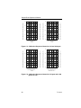
Appendix C shows the Sample-Draw Transmitter calibration response charts.
2.0
GAS CONCENTRATION
IN PPM
400
16
300
12
200
8
100
4
0
2
4
6
8
GAS CONCENTRATION
IN PPM
10
500
20
400
16
300
12
200
8
100
4
0
3
6
9
12
AMPLIFIER/DETECTOR OUTPUT ( MILLIAMPS )
20
AMPLIFIER/DETECTOR OUTPUT ( MILLIVOLTS )
500
AMPLIFIER/DETECTOR OUTPUT ( MILLIAMPS )
AMPLIFIER/DETECTOR OUTPUT ( MILLIVOLTS )
Figure C-1 Calibration Response Charts for 0-1 and 0-2 ppm
15
GAS CONCENTRATION
IN PPM
Figure C-2 Calibration Response Charts for 0-10 and 0-15 ppm
71-0114
37
400
16
300
12
200
8
100
4
0
4
8
12
16
500
20
400
16
300
12
200
8
100
4
0
20
GAS CONCENTRATION
IN PPM
6
12
18
24
AMPLIFIER/DETECTOR OUTPUT ( MILLIAMPS )
20
AMPLIFIER/DETECTOR OUTPUT ( MILLIVOLTS )
500
AMPLIFIER/DETECTOR OUTPUT ( MILLIAMPS )
AMPLIFIER/DETECTOR OUTPUT ( MILLIVOLTS )
Sample Draw Operator’s Manual
30
GAS CONCENTRATION
IN PPM
400
16
300
12
200
8
100
4
0
10
20
30
40
GAS CONCENTRATION
IN PPM
50
500
20
400
16
300
12
200
8
100
4
0
20
40
60
80
AMPLIFIER/DETECTOR OUTPUT ( MILLIAMPS )
20
AMPLIFIER/DETECTOR OUTPUT ( MILLIVOLTS )
500
AMPLIFIER/DETECTOR OUTPUT ( MILLIAMPS )
AMPLIFIER/DETECTOR OUTPUT ( MILLIVOLTS )
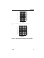
Figure C-3 Calibration Response Charts for 0-20 and 0-30 ppm
100
GAS CONCENTRATION
IN PPM OR % LEL
Figure C-4 Calibration Response Charts for 0-50 ppm and 0-100
ppm or % LEL
38
71-0114
500
20
400
16
300
12
200
AMPLIFIER/DETECTOR OUTPUT ( MILLIAMPS )
AMPLIFIER/DETECTOR OUTPUT ( MILLIVOLTS )
Appendix C
8
100
4
0
100
200
300
400
500
GAS CONCENTRATION
IN PPM
Figure C-5 Calibration Response Charts for 0-500 ppm
20
20.9%
400
16
300
12
200
8
100
4
0
5
10
15
20
25
AMPLIFIER/DETECTOR OUTPUT ( MILLIAMPS )
AMPLIFIER/DETECTOR OUTPUT ( MILLIVOLTS )
500
30
GAS CONCENTRATION
% VOL
Figure C-6 Calibration Response Charts for 0-30% by volume
71-0114
39
Sample Draw Operator’s Manual
40
71-0114