1
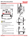
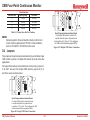
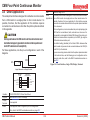
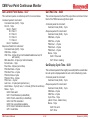
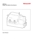
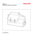
CM4 Four-Point Continuous Monitor
Technical Handbook
•
•
•
•
•
•
TOC
CM4 Overview
Controls and Indicators
Installation
Basic Operation
Calibration Mode Funct.
•
•
•
•
•
•
Review Menu Functions
Setup Menu
Service Menu
Maintenance
Options
Specifications
•
•
•
•
•
•
Fault Listing
Detectable Gases
Printer Options
Serial Comm Protocol
Installation Drawings
Warranty Statement
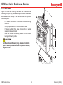
CM4 Four-Point Continuous Monitor
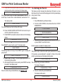
Your Uptime Is Our Top Priority
Because your uptime is our top priority, Honeywell Analytics, Inc. provides you with a 24-hour Emergency Service
Hotline.
During Business Hours:
Honeywell Analytics, Inc. (U.S.A.)
Corporate Headquarters:
(Toll-Free) 847-955-8200
800-323-2000
www.honeywellanalytics.com
24-Hour Emergency Hotline: 847-634-2840
Record your serial number and installation date for easy reference. To save time when calling for service, please have the serial number
of your instrument available.
CM4 Technical Manual
i
Revision 9 (02/08)
CM4 Four-Point Continuous Monitor
Symbols Used on Your Instrument
Overview
Your Honeywell Analytics instrument uses several symbols to provide information. Each symbol provides a graphic representation of
equivalent words. The symbols are easily recognizable in any language.
Below is a listing of symbols used on Honeywell Analytics products and a brief description of what the symbols represent. (Your
instrument model might not use all of the symbols listed here.)
Symbols
Power Switch ON
Caution – Refer to accompanying
documents. Caution statements are used to
indicate hazards or unsafe practices which
could result in minor personal injury or
product or property damage.
Power Switch OFF
Power Indicator LED
Warning – Refer to accompanying
documents. Warning statements are used to
indicate hazards or unsafe practices which
could result in severe personal injury or
death.
Locked Keypad LED
Alarm LED
Equipment Mounting
Position in Rack
Caution – Risk of electrical shock
Caution – Hot Surface
Printer Share Box
Direct Current (D.C.)
Printer
CM4 Technical Manual
Ground Terminal
ii
Revision 9 (02/08)
CM4 Four-Point Continuous Monitor
EMC Considerations
Twisted Pair
Provides for cancelling of magnetic fields.
Overview
Stranded Pair
Provides the greatest surface area MDA Scientific product
testing uses >90% braid with foil (around the bundle);
twisted pair; stranded 24 AWG (minimum wiring for all
qualification and certification testing).
Your Honeywell Analytics instrument has been designed to
comply with applicable Electromagnetic Compatibility (EMC)
standards at the time of manufacture. The design includes filtering,
shielding and bypassing techniques. At the time of certification,
simulated customer Input/Output (I/O) schemes were tested.
Examples:
Belden 83652 2-conductor
Belden 83653 3-conductor
Belden 83654 4-conductor
Belden 83656 6-conductor
All methods used in your equipment for emission supression
and reduction of susceptibility are interactive. Modifications
t o t h e i n s t r u m e n t w i l l m o s t l i ke l y r e s u l t i n i n c r e a s e d
emissions and higher vulnerability to other radiated fields.
All examples are 18 AWG stranded, with 100% shield
coverage.
Shield
Termination
Following the guidelines in this EMC Considerations section will ensure
your instrument maintains the highest degree of EMC integrity. The
guidelines listed apply only to I/O emissions and do not apply to A.C.
and D.C. instrument power connections.
For discrete wire terminations, pigtails to the
cabinet (connector) ground should be extremely
short (absolutely no greater than three inches).
Cabling
At a very minimum, all cables should include a braided shield. Ideal
results have been obtained with twisted pair cabling which has a foil
shield surrounding each pair plus foil and 90% braid shielding around
the bundle. While this yields the best results, it can be very expensive.
In addition, ensure local electrical code requirements are met.
For multiconductor connector terminations, only
360° shielded shells should be used.
Connectors
Cabling Type
All qualification and certification of MDA Scientific products
were achieved with high quality connectors, providing 360°
shield coverage. These connectors generally had metal shells.
The following cable parameters must be considered:
Braid
Must have minimum 90% coverage.
Foil
When used with braid, provides 100% coverage.
Note:
Failure to properly secure the connector to the equipment will result in
high emission levels. Also, poorly constructed or improperly assembled
connectors can be a high source of radiated noise and provide a path
for external signals into the instrument.
Do not use foil alone, it has a tendency to break.
CM4 Technical Manual
Continuation of the shield to the cabinet earth
ground is most important.
iii
Revision 9 (02/08)
CM4 Four-Point Continuous Monitor
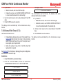
Table of Contents
Your Uptime Is Our Top Priority�������������������������������i
Symbols Used on Your Instrument������������������������ii
Overview������������������������������������������������������������������������ii
Symbols�������������������������������������������������������������������������ii
EMC Considerations����������������������������������������������iii
Overview�����������������������������������������������������������������������iii
Cabling��������������������������������������������������������������������������iii
Cabling Type������������������������������������������������������������ iii
Connectors�������������������������������������������������������������� iii
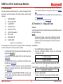
1 CM4 Overview
1.1 Introduction��������������������������������������������������������� 1-2
1.2 Sampling and Monitoring System��������������������� 1-3
1.2.1 Flow Connections���������������������������������������� 1-3
1.2.2 Pump����������������������������������������������������������� 1-3
1.2.3 Filters����������������������������������������������������������� 1-3
1.3 Detection System������������������������������������������������ 1-4
1.3.1 Chemcassette® Carrier ������������������������������� 1-4
1.3.2 Optics and Electronics �������������������������������� 1-4
1.3.3 Chemcassette® Detection System��������������� 1-5
1.3.4 Measuring Gases����������������������������������������� 1-5
1.4 Displays and Controls���������������������������������������� 1-6
1.4.1 Display��������������������������������������������������������� 1-6
1.4.2 Status and Alarm LEDs������������������������������� 1-6
1.4.3 Keypad��������������������������������������������������������� 1-6
1.4.4 Power LED��������������������������������������������������� 1-6
1.4.5 Flow Control������������������������������������������������� 1-6
1.5 Electrical Connections��������������������������������������� 1-6
1.5.1 I/O Panel������������������������������������������������������ 1-6
CM4 Technical Manual
1.5.2 Power Connection���������������������������������������� 1-7
1.5.3 Optional Serial Output��������������������������������� 1-7
1.6 Alarms������������������������������������������������������������������ 1-7
1.6.1 General and Point Gas Alarms�������������������� 1-7
1.6.2 Activating an Alarm�������������������������������������� 1-7
1.7 Instrument Diagnostics�������������������������������������� 1-8
2 Controls and Indicators
2.1 Introduction��������������������������������������������������������� 2-2
2.2 Control Panel������������������������������������������������������� 2-2
2.2.1 Display��������������������������������������������������������� 2-2
2.2.2 LEDs and Point ID Labels���������������������������� 2-3
2.2.3 Keypad��������������������������������������������������������� 2-3
2.2.4 Power Indicator LED������������������������������������ 2-3
2.3 Relays������������������������������������������������������������������ 2-4
2.4 Sample Flow Controls���������������������������������������� 2-4
3 Installation
3.1 Introduction��������������������������������������������������������� 3-2
3.1.1 Mounting Alternatives���������������������������������� 3-2
3.1.2 Accessory Kit����������������������������������������������� 3-2
3.1.3 Installation Steps����������������������������������������� 3-2
3.2 Components and Connections for Installation������ 3-3
3.3 Surveying the Installation Site�������������������������� 3-3
3.3.1 Placement of the CM4 �������������������������������� 3-3
3.3.2 Exposure to Dust and Humidity������������������� 3-3
3.3.3 Sample Transport Time�������������������������������� 3-4
3.3.4 Instrument Dimensions�������������������������������� 3-4
3.4 Sample Locations ���������������������������������������������� 3-4
3.4.1 Sample Line Particulate Filter Use�������������� 3-4
v
Revision 9 (02/08)
CM4 Four-Point Continuous Monitor
Table of Contents
3.4.2 Special Considerations for Positive Pressure� 3-4
3.5 Configuring for Mounting Method��������������������� 3-4
3.5.1 Wall Mount��������������������������������������������������� 3-5
3.5.2 Rack Mount Kit��������������������������������������������� 3-6
3.5.3 Rack Mounting the CM4-P��������������������������� 3-7
3.5.4 Rack Enclosures������������������������������������������ 3-7
3.6 Installing Sample Lines�������������������������������������� 3-9
3.6.1 Sample Line Requirements for Installation�� 3-9
3.6.2 Tubing Connections����������������������������������� 3-10
3.6.3 Sample Line Inlet Connections������������������ 3-10
3.6.4 Point Legend���������������������������������������������� 3-10
3.7 Installing Sample Line Particulate Filters������� 3-11
3.8 Installing Pump Exhaust Line�������������������������� 3-11
3.8.1 Exhaust Line Installation Guidelines���������� 3-11
3.8.2 Exhaust Tubing Specifications ������������������ 3-11
3.9 Connecting AC Power Cord����������������������������� 3-11
3.10 Wiring Relays�������������������������������������������������� 3-12
3.10.1 Relay Contacts����������������������������������������� 3-12
3.10.2 Ratings ���������������������������������������������������� 3-12
3.10.3 Wiring Guidelines������������������������������������� 3-13
3.11 Wiring Optional Current Loop (4-20 mA Output)������3-13
3.12 Loading Chemcassette® Tape������������������������ 3-14
3.13 Power On/Off��������������������������������������������������� 3-14
3.14 Installation Notice������������������������������������������� 3-14
3.15 Function and Cursor Keys����������������������������� 3-15
3.15.1 MONITOR������������������������������������������������ 3-15
3.15.2 PROGRAM���������������������������������������������� 3-15
3.15.3 RESET/ESCAPE������������������������������������� 3-15
CM4 Technical Manual
3.15.4 ENTER����������������������������������������������������� 3-15
3.15.5 CURSOR ARROW LEFT/RIGHT������������� 3-15
4 Basic Operation
4.1 Introduction��������������������������������������������������������� 4-2
4.2 Monitor Mode������������������������������������������������������ 4-2
4.2.1 Exiting Monitor Mode����������������������������������� 4-3
4.2.2 Printing Time Weighted Averages (TWA)
During Monitor Mode�������������������������������������������� 4-3
4.2.3 Point Lock-On During Monitor Mode������������ 4-3
4.2.4 Display Lock-On During Monitor Mode ������� 4-4
4.2.5 Alarm History During Monitor���������������������� 4-4
4.2.6 Fault History During Monitor Mode�������������� 4-5
4.2.7 Display Point Flows During Monitor Mode��� 4-5
4.2.8 Advance Chemcassette Tape During Monitor Mode4-5
4.3 Program Mode����������������������������������������������������� 4-5
4.4 Alarms and Faults����������������������������������������������� 4-6
4.4.1 Alarms���������������������������������������������������������� 4-6
4.4.2 Faults����������������������������������������������������������� 4-6
4.5 Accessing Programming Functions����������������� 4-6
4.5.1 Programming by Scrolling���������������������������� 4-7
4.5.2 Programming Using Direct Numeric Entry��� 4-7
4.6 CM4 Menu Structure������������������������������������������� 4-8
4.7 Keypad Locking Feature������������������������������������ 4-9
5 Calibration Mode Functions
5.1 Introduction��������������������������������������������������������� 5-2
5.2 Function 1.1 – Optics Verify������������������������������� 5-2
5.3 Function 1.2 – Manual K-Factor ����������������������� 5-3
5.4 Function 1.3 – Calibrate Current Loop ������������ 5-4
vi
Revision 9 (02/08)
CM4 Four-Point Continuous Monitor
Table of Contents
7.3 Function 3.2 – Point Parameters����������������������� 7-3
7.3.1 Select Gas Type, Program Alarms and Set Current Loop Full Scale Values�������������������� 7-3
7.3.2 Defining the Point ID������������������������������������ 7-5
7.4 Function 3.3 – Output Options�������������������������� 7-6
7.4.1 Optional COM Port (3.3.1)��������������������������� 7-6
7.4.2 Optional Printer Port (3.3.2)������������������������� 7-7
7.4.3 Printer Format (3.3.3)���������������������������������� 7-8
7.4.4 Relay State (3.3.4)��������������������������������������� 7-9
7.4.5 2 mA Fault Operation (3.3.5)��������������������� 7-10
7.4.6 Enable/Disable Duty Cycle Option (3.3.6)� 7-10
7.5 Function 3.4 – Configuration��������������������������� 7-11
7.6 Function 3.5 – Date & Time������������������������������ 7-12
7.6.2 Set Date & Time (3.5.2)����������������������������� 7-12
7.6.3 Set Display Cycle (3.5.3)��������������������������� 7-13
7.6.4 Set TWA Printout Time (3.5.4)������������������� 7-13
7.6.5 Set Idle Time (3.5.5)���������������������������������� 7-14
7.6.6 Set Duty Cycle (optional) (3.5.6)���������������� 7-14
7.7 Function 3.6 – Access Setup��������������������������� 7-14
7.7.1 Set Key Lock Code������������������������������������ 7-15
7.8 Function 3.7 – Maintenance Set-Up���������������� 7-16
7.8.1 Chemcassette® Counter (3.7.1)����������������� 7-16
7.8.2 Internal Filter Timer (3.7.2)������������������������ 7-16
7.8.3 External Filter Timer (3.7.3)����������������������� 7-17
8 Service Menu
8.1 Introduction��������������������������������������������������������� 8-2
8.2 Function 4.1 – Relay/LED Test �������������������������� 8-2
8.3 Alarm Tests���������������������������������������������������������� 8-3
5.4.1 Selecting the Signal Levels Manually���������� 5-5
5.4.2 Selecting Signal Levels – Automatic Ramping�5-5
5.4.3 Selecting Signal Levels – Step�������������������� 5-6
5.5 Function 1.4 – Tune Current Loop��������������������� 5-6
6 Review Menu Functions
6.1 Introduction��������������������������������������������������������� 6-2
6.2 Function 2.1 – Alarm History����������������������������� 6-2
6.2.1 Print Alarm History��������������������������������������� 6-2
6.2.2 Display Alarm History���������������������������������� 6-3
6.3 Function 2.2 – Fault History ������������������������������ 6-4
6.3.1 Print Fault History���������������������������������������� 6-4
6.3.2 Display Fault History������������������������������������ 6-4
6.4 Function 2.3 – Current TWA ������������������������������ 6-5
6.4.1 Print TWA����������������������������������������������������� 6-5
6.4.2 Display TWA������������������������������������������������� 6-6
6.5 Function 2.4 – Last Power-Down����������������������� 6-6
6.5.1 Print Last Power-Down�������������������������������� 6-6
6.5.2 Display Last Power-Down���������������������������� 6-7
6.6 Function 2.5 – Customer Data �������������������������� 6-7
6.6.1 Print Customer Data������������������������������������ 6-7
6.6.2 Display Customer Data�������������������������������� 6-7
6.7 Function 2.6 – Print Configuration�������������������� 6-8
6.8 Function 2.7 – Instrument Serial Number��������� 6-8
6.9 Function 2.8 – Print Menu�������������������������������� 6-10
7 Setup Menu
7.1 Introduction��������������������������������������������������������� 7-2
7.1.1 Enabling/Disabling the Keypad�������������������� 7-2
7.2 Function 3.1 – Point Enable������������������������������� 7-3
CM4 Technical Manual
vii
Revision 9 (02/08)
CM4 Four-Point Continuous Monitor
Table of Contents
10 Options
10.1 Communications Options������������������������������ 10-2
10.1.1 Serial Communications���������������������������� 10-2
10.1.2 Printers���������������������������������������������������� 10-2
10.2 Remote Alarm Reset Option�������������������������� 10-2
10.2.1 How it Works�������������������������������������������� 10-2
10.2.2 Wiring Considerations������������������������������ 10-3
10.2.3 Using an External Power Supply������������� 10-3
10.2.4 Using the CM4 Monitor’s Internal Power Supply10-3
10.3 Sample Line Integrity Option������������������������� 10-5
A Specifications
A.1 Introduction��������������������������������������������������������A-2
A.2 Filter Compatibility���������������������������������������������A-2
A.3 General Specifications��������������������������������������A-3
A.3.1 CM4������������������������������������������������������������� A-3
A.3.2 CM4-P��������������������������������������������������������� A-3
A.4 Transport Times��������������������������������������������������A-4
B Fault Listing
B.1 Fault Codes���������������������������������������������������������B-2
B.2 Leak Check Procedure��������������������������������������B-8
C Chemcassette® Detectable Gases
D Printer Options
D.1 Overview�������������������������������������������������������������D-2
D.1.1 RS-232C������������������������������������������������������D-2
D.1.2 RS-422��������������������������������������������������������D-2
D.1.3
Desktop Printer�����������������������������������D-2
D.1.4
Enclosure Printer Kit���������������������������D-2
D.1.5
Printer Share Box��������������������������������D-2
8.3.1 Function 4.2.1-Alarm Indicator Test������������� 8-3
8.3.2 Function 4.2.2-Simulated Alarm Test����������� 8-3
8.3.3 Function 4.2.3-Optics Alarm Test����������������� 8-5
8.4 Function 4.3 – Diagnostics�������������������������������� 8-7
8.5 Function 4.4 – Reset System����������������������������� 8-8
8.6 Function 4.5 – Load Chemcassette®/Filter Change������� 8-8
8.7 Function 4.6 – Set Flow������������������������������������ 8-11
8.8 Function 4.7 – MDA Service����������������������������� 8-12
8.9 Function 4.8 – Pump Limits����������������������������� 8-12
8.9.1 Operation��������������������������������������������������� 8-12
8.9.2 Set-up�������������������������������������������������������� 8-12
8.10 Function 4.9 – Reboot������������������������������������ 8-13
9 Maintenance
9.1 Introduction��������������������������������������������������������� 9-2
9.2 Chemcassette® Maintenance����������������������������� 9-2
9.2.1 Remove Carrier�������������������������������������������� 9-2
9.2.2 Verify Optics������������������������������������������������� 9-4
9.2.3 Loading the Carrier�������������������������������������� 9-5
9.2.4 Installing the Chemcassette®����������������������� 9-6
9.2.5 Checking Flowrates������������������������������������� 9-7
9.3 Filter Maintenance���������������������������������������������� 9-8
9.3.1 CM4 Internal Filter Replacement Procedure9-9
9.3.2 Sample Line Particulate Filter�������������������� 9-10
9.3.3 CM4-P Filter Maintenance������������������������� 9-10
9.4 Fuse Replacement�������������������������������������������� 9-11
9.4.1 AC Line Fuse��������������������������������������������� 9-11
9.5 Cleaning the Chemcassette® Optics��������������� 9-12
9.6 Installing Microtube Assembly������������������������ 9-13
CM4 Technical Manual
viii
Revision 9 (02/08)
CM4 Four-Point Continuous Monitor
Table of Contents
D.2.Jumpers���������������������������������������������������������������D-3
D.3.Cabling�����������������������������������������������������������������D-4
D.3.1 EMC Considerations������������������������������������D-4
D.3.2 Cabling Diagrams����������������������������������������D-5
D.4.Instructions and Checklist���������������������������������D-7
D.5.Other Applications����������������������������������������������D-9
E Serial Communications Protocol
E.1 Introduction��������������������������������������������������� E-2
E.1.1 Overview���������������������������������������������������������� E-2
E.1.2 Communication Port��������������������������������������� E-2
E.1.3 Set up Procedure��������������������������������������������� E-3
E.1.4 Protocol Specifics������������������������������������������� E-3
Data and Packets�������������������������������������������������� E-3
Checksum (Check Character)������������������������������� E-4
ACK/NAK Handshake������������������������������������������� E-4
E.2 Protocol Packet Definition���������������������������� E-5
E.2.1 Packet Format ������������������������������������������������ E-5
Start Code������������������������������������������������������������� E-5
Receiver Address�������������������������������������������������� E-5
Transmitter Address���������������������������������������������� E-5
Length������������������������������������������������������������������� E-5
Command������������������������������������������������������������� E-5
Data���������������������������������������������������������������������� E-5
Checksum������������������������������������������������������������� E-5
E.2.2 Generic Data Formats������������������������������������� E-6
Date Format���������������������������������������������������������� E-6
Time Format��������������������������������������������������������� E-6
Date/Time Examples�������������������������������������������� E-6
CM4 Technical Manual
Concentration Data Format Code������������������������� E-6
E.3 Protocol Command Definition��������������������� E-7
E.3.1 Status and Query Commands������������������������ E-7
NOP - 0x28����������������������������������������������������������� E-7
Get System Information - 0x30����������������������������� E-7
Get Unit Status - 0x31������������������������������������������ E-8
Get Idle Time - 0x32������������������������������������������� E-10
Get Date & Time - 0x33�������������������������������������� E-10
Get Maintenance Dates - 0x34��������������������������� E-10
Get Point Configuration - 0x35���������������������������� E-11
Get Alarm History - 0x36������������������������������������ E-11
Get Current Point Status - 0x37�������������������������� E-12
Get TWA Time - 0x38������������������������������������������ E-12
Get Display Cycle Time - 0x39 ����������������������� E-12
Get the Number of Gas Tables Available - 0x3A� E-13
Get Printer Setup - 0x3B������������������������������������� E-13
Get Gas Table Data - 0x3C��������������������������������� E-13
Get Fault History - 0x3D������������������������������������� E-14
Get K-Factor - 0x3E�������������������������������������������� E-14
Get Pyrolyzer Temperatures - 0x42�������������������� E-15
Get Pump Limits - 0x43�������������������������������������� E-15
Get Filter Life - 0x44������������������������������������������� E-15
Get Floating Status - 0x45���������������������������������� E-16
Get One Alarm - 0x47 ���������������������������������������� E-17
E.4 Configuration and Directive Commands�� E-17
Set K-Factor - 0x50��������������������������������������������� E-17
Reset Fault or Alarm - 0x51�������������������������������� E-18
Set Key-Code - 0x52������������������������������������������� E-18
ix
Revision 9 (02/08)
CM4 Four-Point Continuous Monitor
Table of Contents
F Installation Drawing
G Warranty Statement
Chemcassette® Device Warranty Statement������G-2
Chemcassette® Warranties ��������������������������������G-2
Lock Keyboard - 0x53����������������������������������������� E-19
Set 2mA Fault Operation - 0x54������������������������� E-19
Start New Cycle - 0x55��������������������������������������� E-19
Program Chemcassette Counter - 0x56������������� E-20
Set Printer Configuration - 0x57������������������������� E-20
Set Point Enable/Disable – 0x58������������������������� E-21
Set Point Configuration - 0x59���������������������������� E-21
Set TWA Time - 0x5A������������������������������������������ E-22
Set Display Time - 0x5B�������������������������������������� E-22
Set Idle Time - 0x5C������������������������������������������� E-22
Set Date Format - 0x5D�������������������������������������� E-23
Set Date and Time - 0x5E����������������������������������� E-23
Set Relay State - 0x5F���������������������������������������� E-24
End Point Lock-on - 0x60������������������������������������ E-24
Start Point Lock-on - 0x61���������������������������������� E-24
Save Current Configuration - 0x62��������������������� E-25
Restore Configuration - 0x63������������������������������ E-25
Set Duty Cycle - 0x65����������������������������������������� E-25
Set Filter - 0x66�������������������������������������������������� E-26
Get Duty Cycle - 0x69����������������������������������������� E-26
E.5 Operation����������������������������������������������������� E-27
E.5.1 CM4 Instrument Power-up���������������������������� E-27
E.5.2 Commands����������������������������������������������������� E-27
E.5.3 Responses����������������������������������������������������� E-27
E.6 Example Packets����������������������������������������� E-27
E.7 Serial Device Applications������������������������������ E-31
E.7.1 Impedance Matching��������������������������������� E-33
E.8 Glossary������������������������������������������������������������ E-34
CM4 Technical Manual
x
Revision 9 (02/08)
CM4 Four-Point Continuous Monitor
1 CM4 Overview
CM4 Technical Manual
1-1
Revision 9 (02/08)
CM4 Four-Point Continuous Monitor
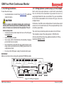
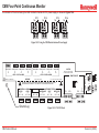
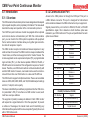
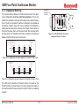
The MDA Scientific CM4 continuously monitors four locations (called
points) for toxic gases. It responds to gases that exceed a programmed
alarm level by:
1.1 Introduction
Point 1
•
Point 3
•
•
Individual
Locations
Point 2
•
Point 4
Triggering alarms and LEDs that warn of high or low
concentrations
Triggering relays to external devices
D i s p l a y i n g t h e p o i n t n u m b e r, g a s t y p e , a n d
gas concentration
Printing the alarm information and storing it in memory (printing
requires optional printer)
The CM4 triggers relays for each individual point for two levels of gas
concentrations. These programmable limits are factory-set at TLV and
2 TLV.
Exhaust
Each point may be up to 300 feet (90 m) from the CM4 location. This
allows operators to monitor gas concentrations in an area removed
from the location where gas may actually be leaking.
The CM4 provides fast response to a wide range of gases. It was
designed for maximum uptime, so filters, detector tape, and even the
entire chassis can be replaced quickly and easily.
The CM4’s flexibility allows it to be easily configured for tabletop use,
rack mounting or wall mounting. The CM4 uses MDA Scientific’s
patented Chemcassette ® technology for rapid, accurate gas
detection.
This section includes information on the CM4’s:
!
STATUS ALARM
1
2
3
4
•
•
•
•
•
•
LOCATION
1
2
3
MONITOR
4
5
6
PROGRAM
7
8
9
RESET
0
ENTER
Figure 1-1: Monitoring Points
CM4 Technical Manual
1-2
Sampling and Monitoring System (Section 1.2)
Detection System (Section 1.3)
Displays and Controls (Section 1.4)
Electrical Connections (Section 1.5)
Alarms (Section 1.6)
Instrument Diagnostics (Section 1.7)
Revision 9 (02/08)
CM4 Four-Point Continuous Monitor
The flow system includes:
1.2 Sampling and Monitoring System
Flow connections (Manifolds) Orifice
Pump
Valves
Filters
Transducers
The system draws sample flow simultaneously from all four points.
Two different types of sample movement are:
•
•
Transport flow: high-velocity, large-volume air movement
through the lines
Sample flow: air admitted to the Chemcassette® detection
system
The high speed of transport flow allows rapid monitoring and response
time when using long lines from monitoring points to the CM4. A small
portion of the transport flow is analyzed to determine concentration
levels.
Note:
On newer style CM4 (S/N XXX-5000 and greater) and all CM4-P
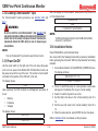
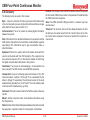
models, the flow controls (item 6) are located on the lower left
of the front panel. An ambient air filter (item 10) is located on
the lower right.
1.2.1 Flow Connections
Flow connections consist of quick-connect ports on the back of the
CM4. There are four inlets, one for each monitored point, and an
exhaust outlet.
1.2.2 Pump
The pump provides a vacuum source for transport and sample flow
during monitoring.
1.2.3 Filters
Filters protect the internal precision orifice from dust particles. Filters
are located in a removable filter block on the top of the instrument.
See Section 9 for information about filter replacement.
3
R
ITO
MON
3
2
1
N
ATIO
LOC
1
TUS
STA
ET
RES
9
8
7
!
M
GRA
PRO
6
5
4
ER
ENT
0
RM
ALA
1
2
3
4
2
!
STA
TU
S ALA
RM
1
2
LO
CATIO
N
3
4
1
4
2
4
3
5
7
0
9
MO
NIT
OR
6
8
PR
OG
RA
M
9
RE
SE
T
EN
TER
6
5
Table Mount
8
10
LEGEND
1. Tape load lever
2. 20-character display
3. Alarm relays
4. Detectors and electronics
5. Status and alarm LEDs
6. Flow controls
7. Keypad
8. Filter block
9. Carrier
10. Air filter
Wall Mount
7
Figure 1-2: CM4 Components and Controls
CM4 Technical Manual
1-3
Revision 9 (02/08)
CM4 Four-Point Continuous Monitor
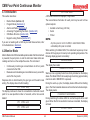
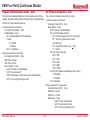
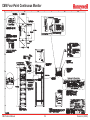
1.3 Detection System
Monitoring Points
The CM4 uses the patented MDA Scientific Chemcassette® detection
system. Chemcassettes® sample and detect a specific gas or family
of gases. The Chemcassette® detection system is included on an
analyzer plate on top of the CM4. The analyzer plate:
•
•
•
•
Retains the Chemcassette® carrier
Manages Chemcassette® transport
Provides optical detection of stain
Directs sample flow through the Chemcassette®
1
2
3
4
Chemcassette Tape
(as viewed in table top position)
Monitoring Points
Components of the detection system include:
•
•
•
Chemcassette® carrier containing Chemcassette detection
tape
Optics and electronics for the detection system
Chemcassette® tape transport mechanism
1.3.1 Chemcassette® Carrier
The Chemcassette® carrier can be pre-loaded with Chemcassette®
tape for rapid tape change.
4
3
2
1
Chemcassette Tape
(as viewed in wall mount position)
Figure 1-3: CM4 Point Stain Pattern
1.3.2 Optics and Electronics
The heart of the Chemcassette® system is an optical detection system
that measures the stain that develops on the Chemcassette® tape.
The CM4’s unique design has four individual detectors, one for each
monitoring point. See Figure 1-3 for point stain location.
To monitor a point, the detection system detects and measures a
specific gas or family of gases in the sample. The CM4 interprets the
data and responds appropriately. See Section 3.4 for instructions
on determining sample locations and Section 3.6 for information on
installing sample lines.
CM4 Technical Manual
1-4
Revision 9 (02/08)
CM4 Four-Point Continuous Monitor
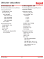
1.3.3 Chemcassette® Detection System
1.3.4 Measuring Gases
1
Chemcassettes® are available for measurement of gases as well as
families of gases. Gases and families the CM4 detects include (See
Appendix C for more information):
2
7
3
Ammonia (NH3)
Arsine (AsH3)
Boron Trifluoride (BF3)
Chlorine (Cl2)
Chlorine Dioxide (ClO2)
Diborane (B2H6)
Dimethyl Amine (DMA)
Dimethyl Hydrazine (UDMH)
Fluorine (F2)
Germane (GeH4)
Hydrogen Bromide (HBr)
Hydrogen Chloride (HCl)
Hydrogen Cyanide (HCN)
Hydrogen Fluoride (HF)
4
5
FLOW
6
Figure 1-4: Chemcassette Detection System
1
2
3
4
Chemcassette® tape
Electronics
LED light source
Detector
Legend
5 Sample inlet
6 Pressure transducer port
7 Sample outlet
1. The sample enters the inlet (5) and passes through the
Chemcassette® tape (1) to the sample outlet (7).
2. Target gas in the sample flow reacts with the Chemcassette®
tape (1) and produces a stain density proportional to the gas
concentration.
3. An LED (3) in the CM4 detector head illuminates the sample
stain. The detector (4) optically measures the stain.
4. The CM4 CPU interprets the stain, then reports a precise
concentration level in parts-per-million (ppm) or parts-perbillion (ppb).
CM4 Technical Manual
Hydrogen Iodide (HI)
Hydrogen Selenide (H2Se)
Hydrogen Sulfide (H2S)
Hydrazine (N2H4)
Monomethyl Hydrazine (MMH)
Nitrogen Dioxide (NO2)
Phosgene (COCl2)
Phosphine (PH3)
Silane (SiH4)
Tert-Butyl Arsine (TBA)
Tert-Butyl Phosphine (TBP)
Triethyl Amine (TEA)
Tetrakis(dimethylamino) titanium (TDMAT)
The pyrolyzer Model CM4-P is specially designed to detect special gases
using high temperature to “crack” those gases into Chemcassette®
detectable gases. Current CM4-P detectable gases are:
Nitrogen Trifluoride (NF3)
Methyl Fluoride (CH3F)
The Model CM4-P is not designed to accept other calibrations, and
cannot be converted.
1-5
Revision 9 (02/08)
CM4 Four-Point Continuous Monitor
Detection is accomplished by routing the sample from each of its four
points through a high-temperature device (pyrolyzer). For example, at
high temperature, NF3 is converted to Hydrogen Fluoride (HF) which
can be detected with a standard Mineral Acids Chemcassette® tape.
The correlation algorithm between HF and NF3 is programmed into
the CM4-P, so the instrument’s display and printouts read directly in
ppm of NF3.
1.4 Displays and Controls
See Figure 1-2
The displays and controls clustered on the front panel of the CM4
include:
Display
Power LED
Status and Alarm LEDs Flow Control
Keypad
1.4.1 Display
The CM4 uses a 1-line, 20-character display. The CM4 display includes
information about concentration and instrument faults and provides
menus for CM4 programming. For more information on the display
panel, see Section 2.
1.4.2 Status and Alarm LEDs
Status LEDs light green when the CM4 is monitoring the point. There
is one LED for each point.
• Light green - normal operation
• Flash green - point lock-on or display lock-on at that point
• Light yellow - instrument fault on that point
• Turn black - not monitoring that point
Note:
Status LEDs also turn yellow or flash to indicate an instrument fault.
CM4 Technical Manual
Alarm LEDs signal gas level alarms for each point. Alarm LEDs:
•
•
Light for Level 1 alarm concentration
Flash for Level 2 alarm concentration
1.4.3 Keypad
Use the keypad to:
• Program the CM4
• Select specific points to monitor
• Print and display programming parameters
1.4.4 Power LED
The power LED at the bottom right of the panel indicates the CM4
is powered up. A blinking yellow power LED indicates the keypad is
locked, requiring a passcode for any CM4 operation.
1.4.5 Flow Control
Four metering valves, one for each point, control the sample flow
through the Chemcassette® detection system.
1.5 Electrical Connections
All electrical connections are made at the rear of the CM4. User
installed wiring connects to a removable relay panel at the top of the
instrument, allowing the chassis to be removed without disturbing
connections.
1.5.1 I/O Panel
The I/O (Input/Output) panel contains connections to 14 form C relays
to activate external devices:
1-6
•
•
A watch dog relay (RY12) which indicates power loss or a
CPU failure
Eight gas alarm relays which indicate Level 1 and Level 2
alarms
Revision 9 (02/08)
CM4 Four-Point Continuous Monitor
•
•
•
Two general gas alarm relays which indicate Level 1 and Level
2 alarms at any point
A Maintenance fault relay (RY8) which indicates the CM4 needs
attention but is continuing to monitor
An Instrument fault relay (RY10) which indicates the CM4 is
unable to monitor one or more points
In addition, the I/O panel includes:
•
•
Terminals for the current loop options, which produce a 4-20
mA output signal in direct variation to the gas concentration
at each point
Terminals for the remote reset option, which permit resetting
of faults and alarms for specific points
1.5.2 Power Connection
Connect AC power to the CM4 at the rear panel. The power switch is
located above the power line connection.
1.5.3 Optional Serial Output
1.6.1 General and Point Gas Alarms
The factory default setting for the Level 1 alarm is the threshold limit
value (TLV) of the monitored gas. The default setting for the Level 2
alarm is two times the TLV. Level 1 and 2 alarms can be factory set
to 1/2 TLV and 1 TLV by specifying part number 1874-0330.
You can also set individual alarm levels for each sample point. Separate
alarm levels for each point provide added protection in critical locations
and allow you to customize the settings to meet the specific needs
of your site.
1.6.2 Activating an Alarm
When the CM4 detects a gas concentration that exceeds a
programmed alarm level, it activates a series of signals. The CM4
continues monitoring during an alarm condition.
Note:
When a Level 2 alarm activates, the Level 1 alarm always activates.
•
Install the optional DB9 (nine-pin) serial data and printer connectors
on the back panel.
1.6 Alarms
The CM4 has alarms that:
• Warn of Level 1 or Level 2 low or high concentrations of the
monitored gas
• Trigger relays to external devices
Section 3.10 describes wiring.
Section 4 describes operation modes and basic operating procedures.
CM4 Technical Manual
1-7
•
•
•
•
•
•
•
Alarm LEDs indicate Level 1 and Level 2 alarms for the
appropriate point
The gas alarm relay contacts activate for the appropriate point
The general alarm contacts activate
The display continues to show the point number, gas type and
gas concentrations
The instrument generates the appropriate current loop signal
(2-20 mA/4-20 mA) and an audible tone
Alarm information is sent to the printer for printing (if enabled)
Alarm data (most recent 16 alarm events) is stored in memory
Alarm information is made available over the optional digital
network port
Revision 9 (02/08)
CM4 Four-Point Continuous Monitor
1.7 Instrument Diagnostics
The CM4 provides diagnostic instrument fault and maintenance
requirement indications. These activate one of the following:
•
•
•
•
•
•
One or both fault relays activate
On-board memory stores most recent eight fault events for
later recall
Fault information is sent to the printer (if enabled)
Status LEDs light yellow for the appropriate point to indicate
instrument faults
The display shows the fault information
If the fault generated is an instrument fault and the CM4 is
appropriately configured, the current level on the optional analog
4-20 mA output port is reduced to 2 mA.
Point
Status LED
Point
Alarm LED
Relays
Activated
Beeping
Audio Alarm
Monitoring
Green
OFF
All OFF
OFF
Current concentrations (each point displayed for four
seconds)
Level 1 alarm
Green
Red
(steady)
- Low level alarm for affected point
- General low level alarm
ON
Current concentrations
Level 2 alarm
Green
Flashing
red
- High and low level alarms for
affected point
- General high and low level alarms
ON
Current concentrations
Low Chemcassette maintenance fault (monitoring continues)
(See Appendix B)
Green
OFF
Maintenance fault
OFF
Current concentrations followed by fault message (as
last message in sequence)
Power interruption or CPU fault
OFF or
random
OFF or
random
Watchdog fault
OFF
Blank or random
Instrument Fault (monitoring continues on unaffected points)
Yellow
OFF
Instrument fault
OFF
Current concentrations followed by fault message (as
last message in sequence)
Instrument fault
(monitoring suspended)
Yellow
OFF
Instrument fault
OFF
Fault Message
Condition
Display
Table 1-1: Instrument Alarms
CM4 Technical Manual
1-8
Revision 9 (02/08)
CM4 Four-Point Continuous Monitor
2 Controls and Indicators
CM4 Technical Manual
2-1
Revision 9 (02/08)
CM4 Four-Point Continuous Monitor
2.1 Introduction
2.2 Control Panel
This section identifies:
The front control panel consists of:
• The control panel display, keypad, and LEDs (Section 2.2)
• Relays (Section 2.3)
• Sample flow controls (Section 2.4)
Note:
On newer style CM4 (S/N XXX-5000 and greater) and all CM4-P
models, the flow controls (item 6) are located on the lower
left of the front panel. An air filter (item 10) is located on the
lower right.
3
Display (1)
Status and alarm LEDs and point ID Labels (2)
Keypad (3)
Power LED indicator (4)
1
2
3
4
ITOR
MON
3
2
1
N
ATIO
LOC
!
US
STAT
M
ALAR
M
GRA
PRO
6
5
4
ET
RES
9
8
7
1
•
•
•
•
ER
ENT
0
1
CM4 Gas Monitor
2
3
4
2
Figure 2-2: Control Panel
!
STA
TUS
ALA
RM
1
LOC
ATI
2
ON
3
4
1
2
1
4
2
4
3
5
7
9
MO
NIT
OR
6
8
0
PRO
GR
9
AM
RES
ET
ENT
ER
5
6
8
Legend
Display
3
Status LED and point ID labels
4
Keypad
Power/Lock LED
2.2.1 Display
Table Mount
10
Wall Mount
7
Figure 2-1: CM4 Components and Controls
1
2
3
4
5
Legend
Tape load lever
6
20-character display
7
Alarm relays
8
Detectors and electronics
9
Status and alarm LEDs
10
CM4 Technical Manual
Flow controls
Keypad
Filter block
Carrier
Air filter
The display is a 1-line by 20-character vacuum fluorescent display
that shows program and operation information.
In the Monitor Mode, if no gas concentration is detected and in the
Idle Mode, the display brightness is reduced to 60% of full brightness.
This feature extends the life of the vacuum fluorescent display.
2-2
Revision 9 (02/08)
CM4 Four-Point Continuous Monitor
2.2.2 LEDs and Point ID Labels
Numeric Keys
Each of the four detection points includes two LEDs:
Use the numeric keys, 1 through 9 and 0, to:
•
•
•
•
Point status LED
Point alarm LED
Enter programming values
Display and select specific detection points
Point Status LED
Function Keys
The monitoring status LEDs indicate the following conditions:
Function keys access menus and functions. Function keys include:
•
•
•
•
Green for the specific point when the CM4 is monitoring that
point
Yellow, steady or flashing indicating fault
Red, steady or flashing indicating alarm
Off when the CM4 is not monitoring that point
Alarm LED
To indicate gas alarm condition, the LEDs:
•
•
Light steady red when Level 1 alarm (low level gas alarm)
occurs for any monitored point
Flash red when Level 2 alarm (high level gas alarm) occurs
for any monitored point
Point ID Labels
Identify each point using the write-on surface provided. Use a fibertipped permanent marker. You can remove any marks with acetone
without damaging the panel.
2.2.3 Keypad
•
•
•
•
MONITOR
PROGRAM
RESET
ENTER
Functions are described in detail later in this manual, Sections 4
through 8.
Cursor Arrow Right/Left Keys
Cursor Arrow Left/Right keys scroll the display backwards and forwards
to program and view information. Pressing the cursor arrow keys twice
while monitoring also advances the tape.
2.2.4 Power Indicator LED
The power indicator LED is:
• On steady green during operation
• Flashes yellow to indicate the keypad is locked
See Section 7.1.1 to activate the keypad using the passcode. See
Section 7.7 for passcode information.
The keypad consists of:
•
•
•
Numeric keys
Function keys
Cursor Arrow Left/Right keys
CM4 Technical Manual
2-3
Revision 9 (02/08)
CM4 Four-Point Continuous Monitor
2.3 Relays
Relays activate to indicate significant change in gas concentration or
instrument status. The relays are on a removable panel on the back of
the instrument. The main chassis of the unit is easily removed while
leaving terminal contacts intact. A single ribbon cable provides the
wiring connection.
Relays provide both normally open and normally closed contacts.
There are separate relays for:
•
Level 1 alarm (low level) for each point (four relays: RY1, RY3,
RY5 and RY7)
• Level 2 alarm (high level) for each point (four relays: RY9, R11,
RY13 and RY14)
• General Level 1 alarm for any monitoring point (RY2)
• General Level 2 alarm for any monitoring point (RY4)
• Instrument fault (RY10)
• Maintenance fault (RY8)
• Watch dog (power loss or CPU failure notification) (RY12)
• One “out of monitoring” (RY6)
See Section 3.11 for information on wiring relays.
2.4 Sample Flow Controls
Flow controls adjust the sample flow through the Chemcassette®. For
details of sample flow adjustments, see Section 8.7.
CM4 Technical Manual
2-4
Revision 9 (02/08)
CM4 Four-Point Continuous Monitor
3 Installation
CM4 Technical Manual
3-1
Revision 9 (02/08)
CM4 Four-Point Continuous Monitor
3.1 Introduction
The installation and initial start-up procedure for the CM4 consists of
six steps, described in this and the following sections:
1. Physical installation of the instrument at the site (Section 3:
Installation).
2. Initial power-up (Section 4: Basic Operation).
3. Instrument programming configurations (Section 7: Set-Up
Menu).
4. Verification of the integrity of the alarm system (Section 8.3:
Function 4.2–Alarm Test).
5. Adjustment of CM4 sample flow rates (Section 8.7: Function
4.6–Set Flow).
6. Verification of the optics system ( Section 5.2: Function
1.1–Optics Verify).
300 feet (90 m) from monitoring points to monitor gas concentrations
in an area removed from the location where gas may actually be
leaking.
3.1.2 Accessory Kit
Your CM4 includes an Accessory Kit (P/N 874265) which contains
this manual (on CD), a calibration card and other items used in
installation.
3.1.3 Installation Steps
Proceed through each of the steps to install the CM4. This section
details physical installation procedures which you should perform in
order:
3.1.1 Mounting Alternatives
•
•
•
•
The CM4 is designed to be operated in four different configurations:
•
•
•
•
Tabletop
Wall mount
Rack kit (customer-supplied rack)
Rack enclosure (MDA-supplied cabinet)
The tabletop is the basic, stand-alone configuration that is used
throughout this manual to show instrument operation. As needed,
certain illustrations will also show the wall mount configuration for
added clarity.
•
•
•
•
•
•
•
Surveying the Installation Site (Section 3.3)
Placement of the CM4 (Section 3.3.1)
Sample Locations (Section 3.4)
Configuring for Mounting Method (Section 3.5 and Section
10 for options)
Installing Sample Lines (Section 3.6)
Installing Sample Line Particulate Filters (Section 3.7)
Installing Pump Exhaust Line (Section 3.8)
Connecting AC Power Cord (Section 3.9)
Wiring Relays (Section 3.10)
Wiring Optional Current Loop (4-20 mA Output) (Section
3.11)
Loading Chemcassette® Tape (Section 3.12)
Wall and rack configurations require either adapter kits or a separate
enclosure. See Section 3.5.3 for information.
When selecting a site for installation of the CM4, consider the mounting
option best suited for your location. Operators can place the CM4 up to
CM4 Technical Manual
3-2
Revision 9 (02/08)
CM4 Four-Point Continuous Monitor
3.2 Components and Connections for Installation 3.3 Surveying the Installation Site
All of the sample line fittings and most electrical terminals for installing
the CM4 are at the back of the instrument.
7
5
6
8
A survey of the site helps you make important decisions before
installing your CM4. Topics in this section assist you with appropriate
placement of the CM4 and in determining if you have special filtering
needs at the sampling location. The site should:
•
Printer
RELAY WIRING
COM
•
•
•
LOW-VOLTAGE
WIRING
4
MODEL CM4 GAS MONITOR
SERIAL #
120 VAC 60 HZ
3 AMPS
3
100 VAC 50/60 HZ
3 AMPS
HONEYWELL ANALYTICS INC.
LINCOLNSHIRE, IL USA
800-323-2000
847-955-8200
MADE IN USA
P/N
DATE CODE:
REV.
220/240 VAC 50/60 HZ
2 AMPS
HONEYWELL ANALYTICS LTD.
POOLE
DORSET, ENGLAND
44-1-202-676-161
LABEL P/N 874267 REV. 10
2
Be remote from the monitored location, not sharing the
atmosphere
Have sufficient ventilation for cabinet cooling
Have power available
Be indoors in an area that is not subject to wide variations
in temperature (not greater than gradients of 25°C per hour)
and humidity
Note:
The specified humidity is 20-80% RH and a temperature
between 10°C to 40°C.
1
9
Figure 3-1: CM4 Back Panel
1
2
3
4
5
Legend
Sample inlets and exhaust
6
Fuse
7
Line power in
8
Power switch
9
Alarm wire panel knockouts
CM4 Technical Manual
COM port
Printer port
Current loop knockout
Serial number label
3.3.1 Placement of the CM4
Install the CM4 in an environmentally-protected setting remote from
the manufacturing or storage locations that it monitors.
Operators can place the CM4 up to 300 feet (90 m) from monitoring
points to monitor gas concentrations in an area removed from the
location where gas may actually be leaking.
3.3.2 Exposure to Dust and Humidity
Exposure to corrosive gases or materials, excess moisture, dust
and other unusual environmental conditions could seriously
hamper the instrument’s monitoring ability and could damage the
instrument.
Always allow room behind the CM4 for ventilation and servicing.
See the installation drawing #874000-I (included with the CM4)
for requirements.
3-3
Revision 9 (02/08)
CM4 Four-Point Continuous Monitor
3.3.3 Sample Transport Time
3.4.1 Sample Line Particulate Filter Use
Although transport times are very short (<40 seconds), you should
install the monitor in a location central to all four points to achieve equal
sample transport times during monitoring. The shorter the sample
line, the shorter the response time. If monitoring a critical point, it
may be desirable to place the instrument near that critical point to
reduce sample transport time for that location. See Appendix A for
transport times.
Refer to Appendix A to install sample line filter and to determine if a
filter can be used at the location.
3.3.4 Instrument Dimensions
Instrument dimensions are important factors in instrument placement.
For the basic tabletop configuration, the dimensions are approximately
9.187 inches (23.3 cm) high. See Section 3.5 for required clearances
and mounting dimension for the optional wall and rack mount
configurations. The CM4 is 17 inches (43 cm) wide and 17-3/4 inches
(45 cm) in depth. The CM4 weighs about 50 pounds (23 kg).
3.4 Sample Locations
Before installing the CM4, evaluate the sampling locations to determine
if excessive dust or moisture are present. Use an external filter at the
end of all sample lines. See Appendix A for selection of appropriate
filter type for the target gas. Dust may be a result of construction as
well as manufacturing activities. Moisture may occur from rain entering
a line at an outdoor sampling location or from condensation caused
by temperature fluctuations. Water condensation in the sample lines
could cause false alarms.
Note:
Variables such as air flow, the molecular weight and temperature
of the sample gas, and the physical conditions of the areas being
monitored influence the placement of the sampling locations. You
may need to consult your company industrial hygiene or safety
officer before installing sample lines to determine your company’s
policy related to sampling locations and monitoring of the desired
sample gas.
CM4 Technical Manual
3.4.2 Special Considerations for Positive Pressure
A transducer inside the CM4 can detect when positive pressure
is present to effectively monitor positive pressure locations. An
operational message indicates when a point has detected positive
pressure.
3.5 Configuring for Mounting Method
The CM4 is factory configured for tabletop use. Rack mounting
and wall mounting require additional procedures for mounting and
connections of cable and tubing.
For optional configurations, Honeywell Analytics supplies the following
installation drawings:
3-4
•
•
•
Wall mount kit: drawing #874014-I
Rack mount kit: drawing #874013-I (customer-supplied rack)
Rack enclosure: drawing #874550-I (MDA-supplied cabinet)
Revision 9 (02/08)
CM4 Four-Point Continuous Monitor
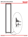
3.5.1 Wall Mount
Figure 3-2 shows wall mounting orientation and dimensions. The
mounting kit supplied by Honeywell Analytics includes all hardware
and fasteners shown except for wall anchors. Here are important
installation points:
•
•
•
•
For detailed installation prints, ask for MDA drawing
#874014-I
Use appropriate anchors to secure brackets to wall
If installing multiple CM4s, allow a minimum 8 inch vertical
separation between brackets
Make sure brackets are securely fastened and level before
locking instrument in position
16.0
(406.40)
!
STAT
US
ALAR
M
1
2
LO
CATIO
N
3
4
1
2
4
3
5
7
MO
0
NIT
OR
6
8
PR
OG
9
RA
M
RE
SE
T
EN
TER
16.25
(412.75)
Caution
The CM4 weighs about 50 pounds (23 kg). Make sure all installation
steps and handling procedures are done with protection and safety
margin for this load.
8.0
(203.00)
Figure 3-2: Wall Mount
CM4 Technical Manual
3-5
Revision 9 (02/08)
CM4 Four-Point Continuous Monitor
3.5.2 Rack Mount Kit
The CM4 Rack Kit includes two custom slides and hardware for
installation in a customer-supplied standard 19 inch rack. For detailed
installation prints, ask for MDA drawing #874550-I.
Figures 3-3, 3-4, and 3-5 show rack mounting installation details.
!
STAT
US
ALA
RM
1
2
LOC
ATIO
N
3
4
!
STATUS ALARM
1
LOCATION
1
1
2
3
MONITOR
4
5
6
PROGRAM
7
8
9
RESET
2
4
3
5
7
2
MON
ITOR
6
8
0
PRO
GRA
9
M
RES
ET
3
0
4
ENTER
ENT
ER
8.75
(222.0)
CM4 Gas Monitor
Figure 3-4: Mounting
Feet
18.31
(465.0)
Figure 3-3: Rack Kit Dimensions
Caution
Verify power is Off before disconnecting customer I/O board.
Follow these points when installing the rack mount:
•
•
•
•
•
Verify proper clearances and dimensions for instrument
placement. See Figure 3-3
Remove feet
Allow 9.00 inch (23 cm) height between units for proper
clearance
Figure 3-4 shows right side fastener locations. Left side
installation is identical
In the recessed position, make sure there is 3-1/4 inch (8.25
cm) clearance for the loop of slack cable as shown in Figure
3-5
CM4 Technical Manual
3-6
Adjustable up to 28" between front/rear mounting rail
3.25
(82.50)
Figure 3-5: Cable Attachments
Revision 9 (02/08)
CM4 Four-Point Continuous Monitor
3.5.3 Rack Mounting the CM4-P
3.5.4 Rack Enclosures
The rack enclosure configurations provide space for up to seven CM4
units (or five CM4 units plus a printer) in an Honeywell Analyticssupplied cabinet.
Caution
The pyrolyzer operates at a very high temperature, therefore CM4-P
units should not be placed immediately adjacent to each other. To
provide effective air circulation around the Model CM4-P cabinets,
the configuration guidelines in Table 3-1 must be maintained.
The recommended quantities and combinations of CM4 and CM4-P
units in a rack is shown in Table 3-1.
Configuration
Qty CM4
1
2
3
4
5
6
7
5
3
1
3
1
0
7
Qty
CM4-P
2
3
4
2
3
4
0
Qty Printer
and Share Box
0
0
0
1
1
1
0
The CM4 rack enclosure will be custom configured for each application.
Supplemental installation and start-up instructions will be provided with
the cabinet. As a pre-installation step, users must prepare floor anchors
to secure the base of the cabinet and prevent tipping. See Figure
3-6. For detailed installation prints , see Appendix F - Installation
Drawings.
Note
There are several kits available to mount CM4 and CM4-P units
into existing rack enclosures. Contact Honeywell Analytics for
more information.
Table 3-1: CM4 Rack Mount Loading Capacity
The Model CM4-P is not retrofittable to “System16-style” enclosures
(P/N 874293). Only “Schroff-Style” enclosures (P/N 1874-0050 and
1874-051) may be used with these units.
CM4 Technical Manual
3-7
Revision 9 (02/08)
CM4 Four-Point Continuous Monitor
Figure 3-6: Rack Enclosure
CM4 Technical Manual
3-8
Revision 9 (02/08)
CM4 Four-Point Continuous Monitor
3.6 Installing Sample Lines
Caution
FEP Teflon tubing must be used to assure proper sample transport.
Other types of tubing are not sufficiently inert. Your Model CM4 includes
a 400 foot (120 m) roll of 1/4-inch (6.35 mm) x 3/16-inch (4.7 mm)
I.D. FEP Teflon sample line tubing included in CM4 kit (P/N 874008).
Additional FEP tubing can be ordered from Honeywell Analytics.
Note:
Honeywell Analytics supplies FEP grade Teflon® tubing with all
new instruments. This tubing is manufactured to our own strict
specifications, and has been purged of all by-products of the
manufacturing process. On occasion, users have supplied their
own tubing. Should you choose to use your own tubing, be advised
that some brands of FEP tubing off-gas small amounts of HF,
which can be detected on start up by MDA Scientific instruments
configured for detecting mineral acids gases (HBr, HCl, HF,
NF3). Before enabling building alarm systems, make certain
that 1) you have installed the correct Chemcassette®, and 2)
your instrument reads zero.
Install sample lines from each location to the CM4, allowing room to
access the back panel. This procedure involves:
• Sample line requirements (Section 3.6.1)
• Tubing connections (Section 3.6.2)
• Sample line inlet connections (Section 3.6.3)
• Point legend (Section 3.6.4)
3.6.1 Sample Line Requirements for Installation
Hydrogen Bromide (HBr) (low level) using the standard Mineral Acids
Chemcassette® (p/n 874337) has a sample line limit of 100 feet.
Hydrogen Bromide (HBr) (low level) using the XP Mineral Acids
Chemcassette® (p/n 1874-9310) has a sample line limit of 300
feet.
Hydrazine (N2H4), Monomethyl Hydrazine (MMH) and 1,1 Dimethyl
Hydrazine (UDMH) have a sample line limit of 50 feet.
•
•
•
•
•
All runs should be as direct as possible to improve transport
time (see Appendix A for transport times)
Make sure there is some slack in the tubing and the power line
to allow access to the back of the cabinet
Avoid running sample lines through areas of great temperature
extremes, such as adjacent to steam or chiller lines
Sample lines should not be crimped, bent to less than a 5
inch (12 cm) radius, or placed in an area where weight could
collapse the tubing. Sample lines should be easily accessible
for periodic inspection.
Leave as many bends as possible exposed for periodic visual
inspection of the line for kinked or damaged tubing
Check each sample line installation for leak integrity after completing
installation of the CM4. The leak check procedure is described in
Appendix B. Also use this procedure to detect leaking or severed
tubing after events, such as construction, which may have affected
the integrity of the tubing.
Follow the general requirements listed below when installing sample
lines.
•
Sample lines should not exceed 300 feet (90 m) in length
CM4 Technical Manual
3-9
Revision 9 (02/08)
CM4 Four-Point Continuous Monitor
depth for a correctly installed sampling line is 1/2 inch to 5/8 inch
(12-16 mm). Verify the insertion depth by holding the tube and marking
with your thumb where it emerges from the fitting. Remove the tube
to measure the insertion depth.
3.6.2 Tubing Connections
To prepare for installation of sample lines, remove the FEP Teflon
tubing (3/16 inch I.D. x 1/4 inch O.D.) from the Installation Kit. The
back of the unit includes five connections:
1 Sample Inlet - Point 1
2 Sample Inlet - Point 2
3 Sample Inlet - Point 3
Caution
4 Sample Inlet - Point 4
5 Exhaust
Improper installation of the tube into the connector results in dilution
of the sample.
Note:
Always perform a leak check after installing all sample lines.
See Appendix B.
3.6.4 Point Legend
!
STATUS ALARM
LOCATION
1
2
Printer
RELAY WIRING
MODEL CM4 GAS MONITOR
SERIAL #
120 VAC 60 HZ
3 AMPS
HONEYWELL ANALYTICS INC.
LINCOLNSHIRE, IL USA
800-323-2000
847-955-8200
MADE IN USA
100 VAC 50/60 HZ
3 AMPS
P/N
DATE CODE:
COM
LOW-VOLTAGE
WIRING
3
REV.
220/240 VAC 50/60 HZ
2 AMPS
HONEYWELL ANALYTICS LTD.
POOLE
DORSET, ENGLAND
44-1-202-676-161
LABEL P/N 874267 REV. 10
4
5
2
1
4
3
Figure 3-9: Point Legend
To keep track of the location corresponding to each point, the CM4
front panel contains an area to the right of the status and alarm LEDs
for point identification. Write the name of each location on the area
next to the point alarm LED on the control panel. Use a fiber-tipped
permanent marker.
Figure 3-7: Tubing Connections
1
2
3
Legend
Sample Inlet - Point 1 4 Sample Inlet - Point 4
Sample Inlet - Point 2 5 Exhaust
Sample Inlet - Point 3
3.6.3 Sample Line Inlet Connections
Each inlet has a quick connect/disconnect fitting with an internal
O-ring and an external grab ring. To install a tube into a sample
line inlet, insert the tube far enough into the fitting to ensure that
the tube has passed through both the external grab ring and the
internal O-ring and is firmly seated against the stop. The insertion
CM4 Technical Manual
3-10
Revision 9 (02/08)
CM4 Four-Point Continuous Monitor
3.7 Installing Sample Line Particulate Filters
3.8.2 Exhaust Tubing Specifications
See Appendix A to determine if you can use sample line filters with
your target gas.
Attach a sample line filter to the sampling end of the line only if you
have determined that environmental dust or moisture is a concern at
the sampling location.
The instrument includes 50 feet (15 m) of 3/16 inch (4.7 mm) I.D. x
1/4 inch (6.35 mm) O.D. polypropylene tubing.
3.9 Connecting AC Power Cord
The CM4 requires a dedicated AC power line. Configurations
include:
•
•
•
Caution
When attempting to use a sample line particulate filter, keep in
mind that excess amounts of dirt in the filters reduce the sample
flow and may affect concentration readings of the analyzer.
120 volt ± 10%; 60 Hertz; 3 amp
100 volt ± 10%; 50 or 60 Hertz; 3 amp
220/240 volts ± 10%; 50 or 60 Hertz; 2 amp
The CM4-P requires:
See Appendix A to determine which filter to use with your target
gas.
•
•
100-120 volt ± 10%; 60 Hertz; 5 amp
220/240 volts ± 10%; 50 or 60 Hertz; 4 amp
3.8 Installing Pump Exhaust Line
Plug the line into a dedicated outlet having sufficient amperage
capacity.
This section describes exhaust connections and installation.
Line voltage should fluctuate no more than ± 10%.
3.8.1 Exhaust Line Installation Guidelines
Properly ventilate the exhaust line, which should not exceed 50 feet
(15 m) in length. If longer distances are required, contact Honeywell
Analytics.
•
•
•
•
If multiple CM4s are installed in the same location, use a
separate line for each exhaust outlet
Do not crimp exhaust lines, or place them in an area where
weight could collapse the tubing, or bend them to less than a
5-inch (12 cm) radius
Leave as many bends as possible exposed for periodic visual
inspection of the line for kinked or damaged tubing
Varying exhaust pressure can induce pump failure
CM4 Technical Manual
3-11
Revision 9 (02/08)
CM4 Four-Point Continuous Monitor
Note:
3.10 Wiring Relays
This section describes relay:
•
•
•
Contacts
Ratings
Wiring guidelines
Make sure that watch dog relays and instrument fault relays are
wired in series to ensure that any fault will trigger a diagnostic
alarm. This will ensure a fail-safe operation.
1
WARNING
2
Use caution when servicing fuses or terminal blocks. Power to
contacts is supplied externally.
3.10.1 Relay Contacts
The CM4 has 13 form C, single-pole, double-throw relays that activate
external alarm devices. Contacts are available for each circuit to
accommodate installation of external devices.
The relay panel may be removed from the CM4 chassis without
disconnecting relay wiring. This allows you to replace the CM4 without
having to reinstall the relay connections.
Each relay has three terminal contacts.
• Normally open
• Fused common
• Normally closed
The terminal blocks for the relay contacts are located on the relay
panel. See Figure 3-11. Relays include:
•
•
•
•
•
•
•
•
Table and Rack Mount
Legend
1
I/O panel (cover removed)
2
Route relay wiring through
knockouts as required
3.10.2 Ratings
To ensure reliable contact operation, the following limits must be
observed:
• 0.1 to 2.0 amps
• @5-24 VDC or
• @5-120 VDC
Four Level 1 alarms (RY1, RY3, RY5, RY7)
Four Level 2 alarms (RY9, R11, RY13, RY14)
One general Level 1 alarm (RY2)
One general Level 2 alarm (RY4)
One watch dog (power loss/CPU failure) relay (RY12)
One maintenance fault relay (RY8)
One instrument fault relay (RY10)
One “Out of Monitoring” relay (RY6)
CM4 Technical Manual
Wall Mount
Figure 3-10: Relay Panel (Cover Removed)
Caution
The alarm relay has a minimum load requirement of greater than 5V
and 100 mA. For reliable relay operation, ensure the alarm circuit
meets these requirements.
The relay contacts are protected by metal oxide varistors rated for
120 VAC maximum operation.
3-12
Revision 9 (02/08)
CM4 Four-Point Continuous Monitor
3.10.3 Wiring Guidelines
3.11 Wiring Optional Current Loop (4-20 mA Output)
To wire the alarm relays:
Each current loop output produces a current which varies linearly
from 4 to 20 mA as the concentration of gas varies from zero to a
user-programmable full scale concentration. The gas concentration
for 20 mA full scale defaults to the full scale of the gas, but can be
configured lower.
•
Use shielded cable or conduit. See Appendix E for additional
cable information.
Caution
Failure to replace and retighten hardware after servicing can
adversely affect instrument performance and EMC compliance. Make
certain all fasteners are reinstalled and firmly tightened. This will
ensure a proper ground.
• Connect grounds to stud at lower left corner of the I/O panel.
See Figure 3-11
• Use #8 hardware provided
• Use a single, solid or stranded wire (not exceeding 14 gauge)
per terminal block connection
• Do not switch DC current with the relay contact unless you are
using counter electromotive force (CEMF) protection such as
a suppression diode
• Do not use the CM4 power supply for external alarm power
Furthermore, the CM4 can be configured lower to reduce these output
currents to 2 mA if certain faults occur. These outputs will drop to zero
mA after a power failure.
The current loop connection points are located on the I/O Panel.
The impedance range of the analog output is 100-800 ohms.
All wiring should follow the wiring guidelines described in Wiring
Guidelines (Section 3.10.3).
IMPORTANT:
Make sure all connections comply with applicable RFI/EMI standards.
NO C NC
2
RY1
NO C NC
3
RY3
RY5
NO C NC
4
RY7
NO C NC
1
!
RY11
NO C NC
3
RY13
NO C NC
4
• FUSES BELOW FLAPS
REMOTE INPUTS
• 2A 125 VAC MAX. CONTACT RATING
EXTERNALLY APPLIED VOLTAGES MAY BE PRESENT AT ALARM TERMINAL BLOCK WITH
INSTRUMENT DISCONNECTED. DISCONNECT AT SOURCE PRIOR TO SERVICING.
!
CAUTION
REPLACE FUSES WITH SAME
TYPE AND RATING SPECIFIED
RY14
LEVEL 2 POINT ALARMS
WARNING
REFER TO USER MANUAL
NO C NC
2
RY9
LEVEL 1 POINT ALARMS
GENERAL ALARMS
LEVEL 1
LEVEL 2
N.O.
SW.
!
TB
18
INSTRUMENT STATUS
MAINTENANCE
FAULT
WATCH DOG
RY2
RY4
RY6
RY8
RY10
NC C NO
NC C NO
NC C NO
NC C NO
NC C NO
PT.1
PT.2
PT.3
PT.4
CURRENT LOOP
NO C NC
1
PT.
1
2
TB20
TB19
3
4
RY12
NC C NO
TB
15
TB
16
TB
17
Ground Lug
Figure 3-11: I/O Panel Connections
CM4 Technical Manual
3-13
Revision 9 (02/08)
CM4 Four-Point Continuous Monitor
3.12 Loading Chemcassette® Tape
For Chemcassette ® loading procedure, see Section 9.2.3 and
9.2.4.
WARNING
Be sure to install the correct Chemcassette®. (See Appendix A for
part number information.) Make sure the label on the Chemcassette®
and the label on the analyzer correspond. Incorrect Chemcassette®
replacement defeats the CM4’s ability to warn of dangerous gas
concentrations.
After this display, the Chemcassette® advances and the pump turns
on. The display shows:
STABILIZING
then
CURRENTLY MONITORING
Note:
The CM4 automatically attempts to enter the Monitoring Mode
whenever it is switched on.
3.14 Installation Notice
Note:
Press PROGRAM to exit the Monitor Mode.
Only one Chemcassette® type should be used with each carrier.
3.13 Power On/Off
Use the rocker switch on the right rear of the unit, above the power
cord, to turn on power to the Model CM4. For Rack Mount units, use
the power panel at the top of the rack. The number of each switch
correlates to the position of the CM4 unit in the rack.
You must perform the following Quick-start procedure at installation
before operating the instrument. With the Chemcassette® and tubing
installed:
1. Access Service Mode 4.8 in the SERVICE (4.SERVICE) menu.
The display will show:
PRESSURE CTS = 832
The display shows:
1 = PUMP 2 = LIMITS
CM4
2. Press 1 to switch the pump on. A new pressure counts value
will appear in the display. This is your “normal reading.”
3. Select 2 to set the High and Low Limits.
4. Set the High Limit value to the “normal reading” plus 52 ±
12.
5. Set the Low Limit value to the “normal reading” minus 52 ±
12.
6. When the values are set, press ENTER to store the values.
Upon power-up, the CM4 conducts a self-diagnostic procedure to
check:
•
•
•
Memory
Hardware
Voltages
The display shows:
SELF TEST
CM4 V3.05
CM4 Technical Manual
Refer to Section 8.9 for more details on this procedure.
3-14
Revision 9 (02/08)
CM4 Four-Point Continuous Monitor
3.15 Function and Cursor Keys
This section describes function keys and cursor keys.
3.15.1 MONITOR
Press MONITOR to initiate monitoring.
3.15.2 PROGRAM
Press PROGRAM to exit the Monitor Mode.
3.15.3 RESET/ESCAPE
Press RESET to reset all CM4 alarm and fault LEDs and relays. Also,
press RESET to escape from subroutines.
3.15.4 ENTER
Press ENTER to confirm configuration changes.
3.15.5 CURSOR ARROW LEFT/RIGHT
Press CURSOR ARROW LEFT/RIGHT to:
•
•
Scroll the display forward/backward to access menus and
functions
View and configure CM4 operating parameters, including
calibrating, reviewing alarm history, reviewing configuration,
setting-up for operation, and servicing the instrument.
CM4 Technical Manual
3-15
Revision 9 (02/08)
CM4 Four-Point Continuous Monitor
4 Basic Operation
CM4 Technical Manual
4-1
Revision 9 (02/08)
CM4 Four-Point Continuous Monitor
4.1 Introduction
PT 2 0 PPB AsH3
A fifth status line will be displayed, if applicable.
This section describes:
•
•
•
•
•
•
The concentration information for each point may be sent to three
optional outputs:
Monitor Mode (Section 4.2)
Program Mode (Section 4.3)
Alarms and Faults (Section 4.4)
Accessing Programming Functions (Section 4.5)
CM4 Menu Structure (Section 4.6)
Keypad Locking Feature (Section 4.7)
If you are not working with a CM4 as you read these sections, refer
to the illustrations in Section 2.
4.2 Monitor Mode
Monitor Mode is the CM4’s standard operation state. After the instrument
is powered, the pump turns on and the instrument takes initial zero
readings and turns on the sample flow valve. The instrument:
•
•
Continuously monitors gas concentrations at all four points
connected to the CM4
Measures and calculates gas concentrations every second for
each of the four points
Response time is determined by the gas type and the alarm level
setting. The display shows the first reading:
PT 1 0 PPB AsH3
The display continues to show the concentration monitored at each
point for a user-specified number of seconds, with a four-second
default:
PT 2 0 PPB AsH3
PT 3 0 PPB AsH3
CM4 Technical Manual
• Isolated current loop (4-20 mA)
• Serial
• Printer
Note:
Any time power is lost to the CM4, it enters Monitor Mode
automatically after power is restored.
When switching On Model CM4-P, the instrument requires up to ten
minutes for the pyrolyzer to heat up to its operating temperature. The
following display appears momentarily:
MONITOR MODE
The display then reads:
WARMING UP 600 SEC
Warm-up time is typically faster than initially indicated on the display
above. The Model CM4-P will usually begin monitoring approximately
one minute after <MONITOR> is pressed.
During the warm-up cycle, the display status LEDs will be flashing
green. The Chemcassette advances as the instrument enters analysis.
The display reads:
CURRENTLY MONITORING
During monitoring, the status LEDs for each active point will be solid
green. When the first concentration has been calculated, the display
will read:
PT1 NF3 = 0 PPM
4-2
Revision 9 (02/08)
CM4 Four-Point Continuous Monitor
4.2.2 Printing Time Weighted Averages (TWA)
During Monitor Mode
Caution
The pyrolyzer operates at a very high temperature. Before performing
any service on the instrument, always wait 30 minutes after switching
off power to allow the pyrolyzer to cool.
If the printer option is installed, press MONITOR twice to print TWAs
while in Monitor Mode. The CM4 prints the current TWA information.
4.2.1 Exiting Monitor Mode
If there is no printer option installed, TWAs can be displayed. Refer
to Section 6.4.2.
To exit Monitor Mode:
4.2.3 Point Lock-On During Monitor Mode
1. Press PROGRAM from Monitor Mode. The CM4 displays:
The Point Lock-On feature causes the CM4 to optimize tape advance
timing of the most rapid updating of concentration on one point.
END MONITOR? 1=Y 0=N
2. Press 1 within two seconds to end monitoring. If the printer
option is available, the display reads:
PRINT TWA
1=Y
1. Press MONITOR.
2. Press 1, 2, 3, or 4 to select the specific point.
0=N
3. Press 1 to print TWA information. Entering 0 exits without
printing TWA information.
After selecting 1, the display advances to:
SELECT PROGRAM
Monitoring ceases on the other points, and the display locks-on to the
one selected point. To enable a specific point:
The CM4 disables the remaining points. The Status LED for the
selected point flashes green. All other point status LEDs are off.
To re-enable disabled points, either:
1. Exit Monitor Mode and then reenter.
or
2. Press MONITOR, then 0.
If a point inadvertently remains locked on, a fault triggers after the
user defined idle time (see Section 7.6.5) has elapsed. The following
fault displays at the end of each point display cycle:
F28 PT LOCK-ON TIMEOUT
Press RESET to clear the fault.
CM4 Technical Manual
4-3
Revision 9 (02/08)
CM4 Four-Point Continuous Monitor
4.2.4 Display Lock-On During Monitor Mode
02/29/00 14:23 CM4-851-0006 ALM HISTORY
ALL POINTS
ABC MANUFACTURING CO., KANSAS CITY, MO
Normally the CM4 displays the gas concentration on all enabled points.
However, the CM4 can also be configured to display only one point
while continuing to monitor all points.
Press 1, 2, 3, or 4 during Monitor Mode to select the specific point.
The CM4 displays only the concentration for the selected point.
The display will not return to normal unless you press 0 or exit and
reenter Monitor Mode.
PT1- CM4-851-0006
02/29/00
14:18 Level 2 Alarm 50.1 PPM NH3-II
02/29/00
14:18 Level 1 Alarm 37.0 PPM NH3-II
4.2.5 Alarm History During Monitor
PT2-CM4-851-0006
02/29/00
14:16 Level 1 Alarm 29.8 PPM NH3-II
Use the alarm history function to print and display up to a maximum
of 16 gas alarms with the most recent alarm shown first.
PT3-CM4-851-0006
02/29/00
14:19 Level 1 Alarm 28.7 PPM NH3-II
Print Alarm History
If the CM4 is equipped with a printer, see Figure 4-1 for an example
of a typical printout. The printout of the alarm history shows the most
recent alarm first for up to 16 total alarms.
To print and display the alarm history, press ENTER followed by the
point desired (1, 2, 3 or 4).
The alarm history is printed (if installed) and displayed showing the
most recent alarm first. The display will scroll through each alarm. Use
the cursor keys to advance through each alarm.
The CM4 sends the alarm history of the selected point to the printer.
The printout shows:
• Instrument serial number
• Current date and time
• Customer name and location
• Point number
• Alarm date and time
• Concentration in ppb or ppm
• Alarm level (1 or 2)
PT4-CM4-851-0006
NO ALARM HISTORY
CM4 Technical Manual
END OF ALARM HISTORY
Figure 4-1: Typical Alarm History Printout
The display returns to normal ten seconds after the last keypad
entry.
Pressing RESET does not clear alarm history.
4-4
Revision 9 (02/08)
CM4 Four-Point Continuous Monitor
4.2.6 Fault History During Monitor Mode
4.2.7 Display Point Flows During Monitor Mode
Use the fault history function to print and display the four most recent
faults and alarms. See Figure 4-2.
Use the display point flows to check sample flows without leaving
monitor mode. To set or check the sample flows, press ENTER followed
by 5. The four flows will be displayed in real time along with the up or
down arrows if they are out of tolerance:
To print and display the fault history, press ENTER followed by 0.
The fault history is printed (if printer is installed) and displayed showing
the most recent fault first. The display will scroll through each fault.
Use the cursor keys to advance through each fault.
The printout of the fault history shows the most recent fault first for up
to eight total faults. The printout includes:
•
•
•
•
•
•
173
The display will update once per second. The display will revert to
normal operation after 20 seconds or after RESET is pressed.
4.3 Program Mode
To access Program Mode:
1. Press PROGRAM from Monitor Mode. The CM4 displays the
message:
END MONITOR? 1=Y 0=N
02/29/05 14:23 CM4-851-0006 FAULT HISTORY
ABC MANUFACTURING CO., Kansas City, MO
TRANSPORT ERROR
02/29/05
14:22 F27
FLOW FAILURE PT1
02/29/05
14:19 F39
LOSS OF FLOW PT4
182
Press the CURSOR RIGHT ARROW twice to advance the tape and
view the stain pattern while remaining in Monitor Mode. Display lock-on
and point lock-on remain active during this procedure. TWA information
is uninterrupted.
The CM4 sends the fault history to the printer.
14:22 F37
165
4.2.8 Advance Chemcassette Tape During Monitor Mode
Instrument serial number
Current date and time
Customer name and location
Fault number (Fxx)
Fault type
Fault date and time
02/29/05
189
2. Press 1 to end Monitor Mode and go to Program Mode.
If you do not press 1 within three seconds, the CM4 returns to Monitor
Mode.
The CM4 goes to Program Mode and displays:
END OF FAULT HISTORY
Figure 4-2: Typical Fault History Printout
SELECT PROGRAM
The display returns to normal 20 seconds after the last keypad
entry.
Press CURSOR ARROW LEFT/RIGHT to select items from the four
program menus.
Pressing RESET does not clear fault history.
CM4 Technical Manual
4-5
Revision 9 (02/08)
CM4 Four-Point Continuous Monitor
Use the CM4 function keys while in Program Mode to:
•
•
•
Level 2 alarms:
Program the CM4 for calibration, fault history, set-up or
service
Access Monitor Mode
Reset fault and alarm relays
Press MONITOR to return to Monitor Mode.
Note:
The CM4 signals a fault after a period of idle time. See Section
7.6.5 for more information.
•
•
•
Display current gas concentration
Beeping audio alarm tone
Flashing Alarm LED
4.4.2 Faults
4.4 Alarms and Faults
If an instrument fault or maintenance fault is detected, the CM4 displays
the most recent fault and a fault code after the last point display. The
display cycles through points being monitored, ending the cycle with
the last fault that occurred during monitoring:
PT 4 0 PPB AsH3
The CM4 continuously displays the current concentrations while
monitoring.
This is followed by the fault information:
F2 LOW FLOW POINT 4
4.4.1 Alarms
This fault information will continue to be displayed until the fault is
reset.
If latching relay is on (default), the Alarm LEDs will indicate a gas
alarm (if gas is detected).
If non-latching is selected, the LEDs will represent the current
concentration (i.e., if current concentration is below Alarm 1, Alarm
LED will be off).
Certain fatal faults will cause the CM4 to suspend monitoring. See
Appendix B.
4.5 Accessing Programming Functions
Programming functions are accessed using two methods:
See Section 7.4.4 for more information.
Note:
During alarms, the display continues to show the current gas
concentration.
•
By scrolling through the menu selections via the arrow keys
(see Section 4.5.1)
•
By direct numeric entry, using the menu structure (see
Section 4.5.2).
Level 1 alarms:
•
•
•
Display current gas concentration
Constant audio alarm tone
Continuously lit Alarm LED
CM4 Technical Manual
4-6
Revision 9 (02/08)
CM4 Four-Point Continuous Monitor
4.5.1 Programming by Scrolling
4.5.2 Programming Using Direct Numeric Entry
1. Press PROGRAM to exit Monitor Mode. The display reads:
END MONITOR? 1=Y 0=N
Refer to the menu structure in Section 4.6. To select an item using
direct numeric entry:
1. Press PROGRAM to exit Monitor Mode. The display reads:
END MONITOR? 1=Y 0=N
2. Press 1 within two seconds to end monitoring. If the printer
option is available, the display reads:
PRINT TWA 1=Y 0=N
3. Press 1 to print TWA information. Entering 0 exits without
printing TWA information.
After selecting 1, the display advances to:
2. Press 1 to end the monitoring session. The display reads:
SELECT PROGRAM
indicates further menu choices are available.
3. Press CURSOR ARROW LEFT/RIGHT to scroll forward/
backward through the four mode (menu) choices. The display
shows modes preceded by a one-digit number.
1 – CALIBRATION MODE
SELECT PROGRAM
indicates further menu choices are available.
4. Press the numeric key corresponding to the menu numbers,
functions, and points (see Section 4.6 for complete menu
listing). For example, to select the alarm history for Point 3,
press the following in sequence:
2 – REVIEW MODE
3 – SETUP MODE
4 – SERVICE MODE
4. Press ENTER when the display shows the desired mode
selection. Depending on the entry, the CM4 displays the menu
(subfunction) choices.
CALIBRATION MODE
•
•
•
REVIEW MENU
Note:
SETUP MENU
SERVICE MENU
5. If the option includes additional functions, the display shows
. Press CURSOR ARROW LEFT/RIGHT to display
menu options.
6. Press ENTER.
CM4 Technical Manual
2 (to access the Review Mode)
1 (to access Alarm History)
3 (to specify Point 3)
4-7
The following sections describe accessing menus and functions
using the scrolling method and function keys. Once you become
familiar with the menu structure, you will be able to access
menus and functions more quickly using direct numeric entry
rather than using the scrolling and function key method.
Revision 9 (02/08)
CM4 Four-Point Continuous Monitor
4.6 CM4 Menu Structure
This section shows the complete CM4 software menu structure,
including the four main menus and the functions available from each
menu.
Refer to this menu structure when using direct numeric entry to quickly
access menus and programming functions.
1. CALIBRATION MODE
1.1 OPTICS VERIFY
1.2 MANUAL K-FACTOR
1.3 CAL CURRENT LOOP
1.4 TUNE CURRENT LOOP
2. REVIEW MODE
2.1 ALARM HISTORY
2.2 FAULT HISTORY
2.3 CURRENT TWA
2.4 LAST POWER DOWN
2.5 CUSTOMER DATA
2.6 PRINT CONFIG
2.7 INST SERIAL #
2.8 PRINT MENU
3. SET-UP MODE
3.1 POINT ENABLE
3.2 POINT PARAMETERS
3.3 OUTPUT OPTIONS
3.3.1
COM PORT
3.3.2
PRINTER PORT
3.3.3
PRINTER FORMAT
3.3.4
RELAY STATE
3.3.5
2 mA FAULT OPER
3.3.6
EN/DIS DUTY CYCLE
3.4 CONFIGURATION
3.5 DATE & TIME
3.5.1
DATE FORMAT
3.5.2
SET DATE & TIME
3.5.3
SET DISPLAY CYCLE
3.5.4
SET TWA TIME
CM4 Technical Manual
3.5.5
SET IDLE TIME
3.5.6
SET DUTY CYCLE
3.6 ACCESS SETUP
3.6.1
EN/DIS KBD LOCK
3.6.2
EN/DIS MENU PASSWD
3.6.3
SET PASSWORD
3.7 MAINT SET-UP
3.7.1 CHEMCASS CTR
3.7.2
INT FILT. LIFETIME
3.7.3 EXT FILT. LIFETIME
4. SERVICE MODE
4.1 RELAY/LED TEST
4.2 ALARM TESTS
4.2.1
ALM INDICATOR TEST
4.2.2
SIMULATED ALM TEST
4.2.3
OPTICS ALM TEST
4.3 DIAGNOSTICS
SOFTWARE VERSION AND KERNEL
GAS TABLE VERSION
FIRMWARE CHECKSUMS
REAL-TIME RAW OPTICS COUNTS
TAPE WINDOWS REMAINING
REAL-TIME POSITION OF TAPE AND COUNT OF EXTRA WINDOWS PULLED
POWER SUPPLY VOLTAGES
OPTICS DAC DRIVE VALUES
Q CALIBRATION FACTORS
FLOW TRANSDUCER OFFSETS
FLOW TRANSDUCER COEFFICIENTS
NEURON ID OF LONWORKS INTERFACE (IF FITTED)
PUMP LIMIT SETTINGS
BAROMETRIC PRESSURE, OPTICS TEMP, AND INTERNAL TEMP
TIMESTAMP OF ERASURE OF FAULT AND ALARM HISTORIES
4.4 RESET SYSTEM
4.5 LOAD CHEMCASSETTE
4.6 SET FLOW
4.7 MDA SERVICE
4-8
Revision 9 (02/08)
CM4 Four-Point Continuous Monitor
4.8 PUMP LIMITS
4.7 Keypad Locking Feature
Purpose
The keypad locking feature prevents unauthorized personnel from
entering any information into the CM4 keypad without knowledge of a
five-digit password. Without the password, for example, it is impossible
to reset faults, change alarm levels or set K-factors. The keypad lock
cannot be defeated by cycling the power on and off.
Note:
If the password is lost or forgotten, contact Honeywell Analytics
Service for assistance.
Instructions
Refer to Section 7.7 to enable the keypad lock feature. By default it
is disabled. Set the password to some desired value between 90000
and 99999.
The power LED in the lower right corner of the CM4 control panel
indicates the status of the keypad. Steady green indicates the keypad
is unlocked. Flashing yellow indicates it is locked.
To set the keypad locking feature:
1. Enter Monitor Mode by pressing MONITOR and waiting at least
10 seconds for the tape to advance.
2. Enter the five-digit password on the keypad with about one
second delay between keystrokes.
3. Verify from the power LED that the new state of the keypad is
as desired. The character display will not provide any indication
of the change.
Note:
The keypad is unlocked by entering the password again.
CM4 Technical Manual
4-9
Revision 9 (02/08)
CM4 Four-Point Continuous Monitor
CM4 Technical Manual
4-10
Revision 9 (02/08)
CM4 Four-Point Continuous Monitor
CM4 Technical Manual
4-11
Revision 9 (02/08)
CM4 Four-Point Continuous Monitor
CM4 Technical Manual
4-12
Revision 9 (02/08)
CM4 Four-Point Continuous Monitor
5 Calibration Mode
Functions
CM4 Technical Manual
5-1
Revision 9 (02/08)
CM4 Four-Point Continuous Monitor
5.1 Introduction
5.2 Function 1.1 – Optics Verify
Use the Calibration Mode to:
•
•
CM4 OPTICS TEST CARD
Perform tests
Make adjustments to Chemcassette Analyzer calibration
INSTRUCTIONS
INSERT
The Calibration Mode offers four functions:
1 CALIBRATION MODE
1.1
1.2
1.3
1.4
OPTICS VERIFY
MANUAL K-FACTOR
CAL CURRENT LOOP
TUNE CURRENT LOOP
FOR OPTICS VERIFICATION PROCEDURE,
ENTER CALIBRATION MODE 1.1, OPTICS VERIFY
SEE MANUAL FOR DETAILS.
STAIN 1
The following is an overview of each of the four functions. The following
sections describe each of these options in detail:
•
1.1 OPTICS VERIFY verifies proper operation of the
Chemcassette optics system (see Section 5.2)
•
1.2 MANUAL K-FACTOR permits entry of a new K-factor
for each particular point (see Section 5.3)
•
1.3 CALIBRATE CURRENT LOOP controls the optional
external analog output for testing and installation (see
Section 5.4)
•
1.4 TUNE CURRENT LOOP controls the adjustment of
the CM4 monitor’s output level (see Section 5.5)
Figure 5-2: Verification Card
Purpose
Use the Optics Verify function and the Optics Verification Card to verify
proper operation of the Chemcassette Analyzer’s optics system. The
CM4 compares the nominal stain values stored in the instrument’s
memory to the values the Optics Verification Card produces.
Instructions
1. Press PROGRAM to exit Monitor Mode.
2. From the 1–CALIBRATION MODE, choose the subfunction
1–OPTICS VERIFY.
1 – CALIBRATION MODE
1 – OPTICS VERIFY
INSERT STAIN 1 PRESS
CM4 Technical Manual
5-2
Revision 9 (02/08)
CM4 Four-Point Continuous Monitor
3. Open the tape load lever and remove the carrier. (See Figure
9-1.)
4. Insert the verification card into the detector head with Stain
1 facing the front of the CM4. Make sure that Stain 1 is fully
inserted into the detector head.
5. Carefully close the tape load lever.
6. Press CURSOR ARROW RIGHT on the numeric keypad. The
readings for Stain 1 are stored. The display reads:
INSERT STAIN 2 PRESS
7. Open the tape load lever.
8. Remove the verification card.
9. Turn the card and fully insert Stain 2.
10.Carefully close the tape load lever.
11.Press CURSOR ARROW RIGHT.
The display shows one of two messages:
Note:
Some local fire ordinances require certified calibration at
installation or annual intervals. While dynamic calibration is
not required for proper operation of the Model CM4, Honeywell
Analytics offers an optional Z-Cal calibration program which can
quickly and safely satisfy your local needs. Contact Honeywell
Analytics’ Service department for this service.
Note:
For detailed instructions on gas calibration, refer to Technical Note
971092, “Gas Verification of Chemcassette Monitors.”
The Manual K-factor adjusts the calculated concentration of a CM4
point. The K-factor is set at 1.000 for all gases during factory gas
calibration. Change the factor only if the instrument’s concentration
readings do not match that of a known calibration gas.
Use a test gas of known concentration and
at ambient humidity when using this function
to re-calibrate the CM4.
VERIFY SUCCESSFUL
or
F24 OPTICS FAIL
12.Open the tape load lever and remove the verification card.
If the optics verification is not successful, repeat the procedure if it
not successful after the second test, see Section 9.5, Cleaning the
Chemcassette Optics. Once the cleaning is complete, repeat the optics
verification procedure. Contact Honeywell Analytics if the instrument
prints and displays the error message after a second optics verification
attempt.
13.Reinstall carrier and close tape load lever.
5.3 Function 1.2 – Manual K-Factor
A K-factor is the numeric result of a formula used to adjust the CM4
output of gas concentrations. The K-factor may be used to change
the sensitivity of the instrument. Adjustments to concentration are
made after calculation of concentration, and before the following are
determined:
Display
Serial output
Optional current loop (4-20 mA) Exceeding alarm level
The factory-set K-factor is 1.000 for all gases.
To calculate a new K-factor, use the following formula:
Press RESET to return to the Calibration main menu.
CM4 Technical Manual
K=
5-3
True Concentration Value of Test Gas
CM4 Reading
Revision 9 (02/08)
CM4 Four-Point Continuous Monitor
K-factor range limits are 0.200 to 5.000. Using a value outside of
these limits displays the following, after which the CM4 returns to the
previous display:
OUT OF LIMITS
WARNING
Use appropriate safety precautions when handling toxic gases.
Properly vent toxic gases.
Note:
K-factors should be 1.000 unless actual gas calibration
procedures are performed.
PT 1 K-FACTOR = 1.000
5.4 Function 1.3 – Calibrate Current Loop
Instructions
Purpose
1. Press PROGRAM to exit Monitor Mode.
2. From the 1–CALIBRATION MODE, choose the subfunction
2–MANUAL K-FACTOR.
1 – CALIBRATION MODE
2 – MANUAL K-FACTOR
The display now shows:
SELECT POINT
3. Use the numeric keys to specify the point. The display shows
the current K-factor:
PT 1 K-FACTOR = 1.000
4. U s e t h e n u m e r i c k e y s t o e n t e r t h e n e w
K-factor.
5. Press either:
• ENTER to save the new entry and return to the Calibration
Mode
or
• RESET to return to the Calibration Mode without changing
any data
The Calibrate Current Loop function calibrates the external analog
devices connected to the module by generating a 2 mA to 20 mA
analog signal from each individual point. If 2 mA fault indication is
disabled via menu function 3.3.5, then the minimum current will change
from 2 mA to 4 mA. This function provides three methods to calibrate
connected devices:
•
•
•
Toggling between 2 mA, 4 mA, and 20 mA signal levels
Automatically changing output signal levels beginning at 2 mA
and going up to 20 mA
Step up the current loop from 4 mA to 20 mA in 1 mA
increments.
Repeat Steps 1 through 5 to adjust the calculated concentration for
each point, if required.
CM4 Technical Manual
5-4
Revision 9 (02/08)
CM4 Four-Point Continuous Monitor
5.4.1 Selecting the Signal Levels Manually
5.4.2 Selecting Signal Levels – Automatic Ramping
Purpose
1. Press PROGRAM to exit Monitor Mode.
2. From the 1–CALIBRATION MODE, choose CALIBRATION
MENU, then the subfunction 3–CALIBRATE CURRENT
LOOP.
The Calibrate Current Loop function allows selection of the signal level
for each individual point.
Instructions
1 – CALIBRATION MODE
1. Press PROGRAM to exit Monitor Mode.
2. From the 1–CALIBRATION MODE, choose CALIBRATION
MENU, then the subfunction 3–CALCULATE CURRENT
LOOP.
CALIBRATION MENU <>
3 – CAL CURRENT LOOP
The display reads:
1 – CALIBRATION MODE
SELECT POINT
3. Use the numeric keys to specify a point. The displays reads:
PT 1 CAL 1=MAN 2=RAMP 3=STEP
4. Press 2. The display shows the output for the selected point,
beginning at 2 mA, then 4 mA, 8 mA, 12 mA, 16 mA, and
ending at 20 mA. Each output level is displayed 5 seconds.
The display reads:
PT 1 RAMP = 2 mA
CALIBRATION MENU <>
3 – CAL CURRENT LOOP
The display reads:
SELECT POINT
3. Use the numeric keys to specify a point. The screen
displays:
PT 1 CAL 1=MAN 2=RAMP 3=STEP
4. Press 1. The selected output point drops automatically to 2 mA
or remains at 4 mA, depending on whether 2 mA fault operation
is set (see Section 7.4.5). The display reads:
PT 1 2 mA PRESS
20 mA
5. Press CURSOR ARROW RIGHT to toggle the output between
2 mA to 20 mA. The display reads:
PT 1 20 mA PRESS
2 mA
Press RESET to return to the Calibration Mode without toggling the
test levels.
CM4 Technical Manual
PT 1 RAMP = 4 mA
PT 1 RAMP = 8 mA
PT 1 RAMP = 12 mA
PT 1 RAMP = 16 mA
PT 1 RAMP = 20 mA
The CM4 repeats the sequence showing level of output, from 4 mA to
20 mA (or 2 mA to 20 mA if selected). Press RESET twice to return to
the Calibration Mode.
5-5
Revision 9 (02/08)
CM4 Four-Point Continuous Monitor
5.4.3 Selecting Signal Levels – Step
1. Press PROGRAM to exit Monitor Mode.
2. From the 1–CALIBRATION MODE, choose CALIBRATION
MENU, then the subfunction 3–CALIBRATE CURRENT
LOOP.
This is necessary only if new current loop hardware has been field
installed.
Instructions
To access Tune Current Loop:
1. Press PROGRAM to exit the Monitor Mode.
2. From the 1–CALIBRATION MODE, choose the subfunction
4–Tune Current Loop, then SELECT POINT.
1 – CALIBRATION MODE
CALIBRATION MENU <>
1 – CALIBRATION MODE
3 – CAL CURRENT LOOP
4 – TUNE CURRENT LOOP
The display reads:
SELECT POINT
3. Use the numeric keys to specify a point. The displays reads:
PT 1 CAL 1=MAN 2=RAMP 3=STEP
4. Press 3. The display shows the output for the selected point,
which will be set at 4 mA, whether or not a 2 mA fault operation
is enabled. The current loop can be lowered (decremented) to
20 mA if a 2 mA fault indication is enabled.
You are able to use the arrow keys to adjust the current loop from 4
mA to 20 mA in 1 mA increments. The display reads:
PT 2 CURR = 04 mA
PT 2 CURR = 07 mA
Press RESET twice to return to the Calibration MENU.
BOARD NOT FOUND
This message is displayed on newer CM4s if the optional current
output board is absent or defective.
LOAD DEFAULT 1=Y 0=N
This message is displayed only on newer CM4s.
If “1” is chosen then the factory calibration parameters will be
loaded.
4 mA = 712
The user may change the DAC endpoint value corresponding
to 4 mA by pressing the arrow keys. However this should not
be performed without a known accurate external ammeter
and Technical Note T/N 1988-0040. Press <ENTER> to proceed.
20 mA = 3750
5.5 Function 1.4 – Tune Current Loop
Purpose
Similarly, this permits changing the 20 mA DAC endpoint. Press
<ENTER> to proceed.
The Tune Current Loop function allows you to adjust the CM4 monitor’s
output level so that it is correlated from zero to full scale with a driven
device (an instrument used to monitor 4-20 mA output).
SELECT POINT
The above procedure should be repeated for all four points.
CM4 Technical Manual
5-6
Revision 9 (02/08)
CM4 Four-Point Continuous Monitor
6 Review Menu Functions
CM4 Technical Manual
6-1
Revision 9 (02/08)
CM4 Four-Point Continuous Monitor
6.1 Introduction
•
The Review Menu contains eight functions which permit viewing
data. It is not possible to change the CM4 configuration with these
functions.
•
2 REVIEW MENU
6.2 Function 2.1 – Alarm History
2.1 ALARM HISTORY
2.2 FAULT HISTORY
2.3 CURRENT TWA
2.4 LAST POWER DOWN
6.2.1 Print Alarm History
2.5 CUSTOMER DATA
2.6 PRINT CONFIGURATION
If the CM4 is equipped with a printer, see Figure 6-2 for an example
of a typical alarm history printout.
2.7 INST. SER. NUMBER
2.8 PRINT MENU
Use the alarm history function to print or display up to a maximum of
16 gas alarms with the most recent alarm shown first.
Figure 6-1: Review Mode Menu
The following is an overview of each of the eight options. The following
sections describe each of these options in detail:
•
•
•
•
•
•
2.6 PRINT CONFIGURATION prints the programmed
configuration for the system (see Section 6.7)
2.7 INST. SER. NUMBER displays CM4 serial number (see
Section 6.8)
2.8 PRINT MENU prints the CM4 menu options (see Section 6.9)
2.1 ALARM HISTORY displays and prints up to 16 gas alarms
with the most recent alarm shown first (see Section 6.2)
2.2 FAULT HISTORY displays and prints up to eight faults with
the most recent shown first (see Section 6.3)
2.3 CURRENT TWA displays and prints the current Time
Weighted Average (TWA) for each point that has been
monitored since the start of the current 8-hour TWA (see
Section 6.4)
2.4 LAST POWER DOWN displays the most recent powerdown and power-up date and time (see Section 6.5)
2.5 CUSTOMER DATA displays customer name and location
(see Section 6.6)
CM4 Technical Manual
Purpose
The printout of the alarm history shows the most recent alarm first for
up to 16 total alarms. The printout shows:
• Instrument serial number
• Current date and time
• Customer name and location
• Point number
• Alarm date and time
• Concentration in ppb or ppm
• Alarm levels
Instructions
6-2
1. Press PROGRAM to exit Monitor Mode.
2. At the REVIEW MENU display, press 1 or RIGHT ARROW and
ENTER to select alarm history.
The display reads:
1 – ALARM HISTORY
Revision 9 (02/08)
CM4 Four-Point Continuous Monitor
3. Use the numeric keys to specify a point, or press ENTER to
select the alarm history of all monitored points.
The display briefly shows:
ALM HISTORY ALL PTS
or
PT 1 ALARM HISTORY
The display then reads (for both):
1 = DISPLAY 2 = PRINT
4. Press 2 to print the alarm history.
6.2.2 Display Alarm History
Purpose
The alarm history display shows alarm:
•
•
•
•
Instructions
The CM4 sends the alarm history to the printer.
05/15/98 09:46 CM4-851-0000 ALM HISTORY ALL POINTS
ABC MANUFACTURING CO., CHICAGO, IL
PT1 CM4-851-0000
NO ALARM HISTORY
PT2 CM4-851-0000
05/15/98
08:33
05/14/98
08:42
LEVEL 1 ALARM
LEVEL 1 ALARM
27.8 PPM NH3-II
27.6 PPM NH3-II
PT3 CM4-851-0000
NO ALARM HISTORY
PT-4-CM4-851-0000
NO ALARM HISTORY
1. Press PROGRAM to exit Monitor Mode.
2. At the REVIEW MENU display, press 1 or CURSOR RIGHT
ARROW.
The display reads:
1 – ALARM HISTORY
3. Use the numeric keys to specify a point, or press ENTER to
select the alarm history of all monitored points.
The display briefly shows:
ALM HISTORY ALL PTS
or
PT 1 ALARM HISTORY
The display then reads (for both):
1 = DISPLAY 2 = PRINT
4. Press 1 to display the alarm history.
END OF ALARM HISTORY
Figure 6-2: Typical Alarm History Printout
Alarm history is not cleared using the RESET key. The display returns
to normal after ten seconds.
The CM4 stores up to 16 alarms. Press CURSOR ARROW LEFT/
RIGHT to scroll through the list of alarms. The CM4 displays date,
time, point number, concentration, gas and alarm level.
Press RESET to return to the Review Menu.
CM4 Technical Manual
Point number
Concentration
Time
Level
5. Press either:
• The CURSOR ARROW LEFT/RIGHT to scroll the display
6-3
Revision 9 (02/08)
CM4 Four-Point Continuous Monitor
•
forward/backward to the next/previous event stored
or
ENTER to re-scroll the event just displayed
PT 1
56 PPB ASH3
2 – REVIEW MODE
2 – FAULT HISTORY
The display reads:
1 = DISPLAY 2 = PRINT
3. Press 2 to print the fault history.
12/27/95 09:31 L2
Alarm history is not cleared using the RESET key.
The CM4 sends the fault history to the printer.
Press RESET to return to the Review menu.
08/26/05 13:51 CM4-851-0000 FAULT HISTORY
ABC MANUFACTURING CO., CHICAGO, IL
6.3 Function 2.2 – Fault History
Use the fault history function to print and display the eight most recent
faults and alarms.
08/26/05
10:34
F12
END OF CASSETTE
08/25/05
09:15
F8
Chemcassette SUPPLY LOW
6.3.1 Print Fault History
See Figure 6-3 for a typical example of a fault history printout.
07/26/05
08:33
F9
GATE OPEN DURING MONITOR
Purpose
06/21/05
The printout of the fault history shows the most recent fault first for up
to eight total faults. The printout includes:
•
•
•
•
•
•
Instrument serial number
Current date and time
Customer name and location
Fault number (FXX)
Fault type
Fault date and time
F15
FLASH CARD ERROR
Figure 6-3: Typical Fault History Printout
Fault history is not cleared using the RESET key.
6.3.2 Display Fault History
Purpose
The fault history display shows fault:
•
•
•
Instructions
1. Press PROGRAM to exit Monitor Mode.
2. From the 2–REVIEW MENU, choose the subfunction 2–FAULT
HISTORY.
CM4 Technical Manual
15:50
Number
Name
Date and time
Instructions
6-4
1. Press PROGRAM to exit Monitor Mode.
2. From the 2–REVIEW MENU, choose the subfunction 2–FAULT
HISTORY.
Revision 9 (02/08)
CM4 Four-Point Continuous Monitor
•
•
2 – REVIEW MODE
2 – FAULT HISTORY
3. Press 1 to display the fault history.
F12 END OF CASSETTE
Instructions
08/26/05 10:30
The display shows the last eight faults stored in fault history.
4. Press either:
• CURSOR ARROW LEFT/RIGHT to scroll forward/backward
to the next/previous event stored
or
• ENTER to repeat the event just displayed
Fault history is not cleared using the RESET key. Press RESET to
return to the Review Menu.
6.4 Function 2.3 – Current TWA
1. Press PROGRAM to exit Monitor Mode.
2. From the 2–REVIEW MENU, choose the subfunction
3–CURRENT TWA.
2 – REVIEW MODE
6.4.1 Print TWA
08/26/05 13:51 CM4-851-0000 TWA
ABC MANUFACTURING CO., CHICAGO, IL
START TIME:
08/26/05 03:56
END TIME:
08/26/05 11:26
ELAPSED TIME:
See Figure 6-4 for an example of a typical TWA printout.
Purpose
The printout of the TWA shows:
Instrument serial number
Current date and time
Customer name and location
Start and end time
CM4 Technical Manual
3 – CURRENT TWA
The display reads:
1 = DISPLAY 2 = PRINT
3. Press 2 to print the TWA history.
The CM4 calculates and prints TWA information based upon the
elapsed time (maximum of 8 hours) from the last entry into Monitor
Mode, power-up, or completed TWA printout until the last sample prior
to leaving Monitor Mode.
Use the Current TWA (Time Weighted Average) function to display or
print the current TWA for each point monitored since the start of the
current 8-hour TWA. The TWA is the concentration of gas measured
and averaged over the entire period.
•
•
•
•
Elapsed time
Concentration levels for each point
7 HOURS 30 MINUTES
POINT 1
GASCAB
16 PPB AsH3
POINT 2
VALVEBOX
8 PPB
AsH3
POINT 3
OPZONE
0 PPB
AsH3
POINT 4
EXHDUCT
0 PPB
AsH3
Figure 6-4: TWA Printout
6-5
Revision 9 (02/08)
CM4 Four-Point Continuous Monitor
6.4.2 Display TWA
6.5 Function 2.4 – Last Power-Down
Purpose
Use the last power-down function to print and display the most recent
power-down and power-up date and time.
The Current TWA display shows:
•
•
•
•
Purpose
Current TWA start time
Current TWA end time
Elapsed time
Concentration levels for each point
Instructions
1. Press PROGRAM to exit Monitor Mode.
2. From the 2–REVIEW MENU, choose the subfunction
3–CURRENT TWA.
2 – REVIEW MODE
3 – CURRENT TWA
The display reads:
1 = DISPLAY 2 = PRINT
3. Press 1 to display the TWA information.
4. Press CURSOR ARROW LEFT/RIGHT to scroll forward/
backward to the next/previous display.
START 08/26/05 03:56
Last power-down information which the CM4 prints and displays
includes:
• Instrument serial number
• Current date and time
• Date and time power was interrupted
• Date and time power was restored
6.5.1 Print Last Power-Down
See Figure 6-5 for an example of a typical last power-down function printout.
Instructions
1. Press PROGRAM to exit Monitor Mode.
2. From the 2–REVIEW MENU, choose the subfunction 4–LAST
POWER DOWN.
2 – REVIEW MODE
4 – LAST POWER DOWN
The display reads:
1 = DISPLAY 2 = PRINT
3. Press 2 to send the information to the printer.
END 08/26/05 11:26
CM4-851-0000
08/26/05
10:22
ELAPSED 07HRS 30MIN
The display shows, in sequence beginning at point 1, accumulated
concentrations for all four points.
POWER INTERRUPTED 05/26/05 10:15
POWER RESTORED
06/01/05 07:30
Figure 6-5: Typical Last Power-Down Printout
Press RESET to return to the Review Menu.
The CM4 also prints this information when power is restored after a
power loss.
CM4 Technical Manual
6-6
Revision 9 (02/08)
CM4 Four-Point Continuous Monitor
6.5.2 Display Last Power-Down
6.6.1 Print Customer Data
Purpose
Purpose
The display last power-down function displays the same information
for the last power-down as is sent to the printer, described in the
previous section.
The CM4 prints the following customer information:
Instructions
•
•
Name
Location
Instructions
1. Press PROGRAM to exit Monitor Mode.
2. From the 2–REVIEW MENU, choose the subfunction 4–LAST
POWER DOWN.
2 – REVIEW MODE
1. Press PROGRAM to exit Monitor Mode.
2. From the 2–REVIEW MENU, choose the subfunction
5–CUSTOMER DATA.
4 – LAST POWER DOWN
The display reads:
1 = DISPLAY 2 = PRINT
3. Press 1 to display the last power-down information.
PWRDN 05/26/05 10:15
5 – CUSTOMER DATA
The display reads:
1=DISPLAY 2=PRINT
3. Press 2 to print the customer name and location.
2 – REVIEW MODE
6.6.2 Display Customer Data
PWRUP 06/01/05 07:30
The display alternates the power-down/power-up messages until
RESET is pressed.
6.6 Function 2.5 – Customer Data
Use the customer data function to print and display information about
the customer. Honeywell Analytics programs and stores the customer
name and location in the CM4. This information is included in TWA
and other printouts.
Purpose
Use the Display Customer Data function to display the same
information about the customer as is sent to the printer, described in
the previous section.
Instructions
1. Press PROGRAM to exit Monitor Mode.
2. From the 2–REVIEW MENU, choose the subfunction
5–CUSTOMER DATA.
2 – REVIEW MODE
5 – CUSTOMER DATA
CM4 Technical Manual
6-7
Revision 9 (02/08)
CM4 Four-Point Continuous Monitor
The display reads:
1 = DISPLAY 2 = PRINT
3. Press 1 to display the customer data. Press 1 again to alternate
between the two lines of customer data.
ABC MANUFACTURING
CHICAGO, ILL
Press RESET to return to the Review Menu
6.7 Function 2.6 – Print Configuration
Purpose
Use the Print Configuration function to print the preprogrammed
system configuration, including:
•
•
•
•
The CM4 prints the system configuration information, shown on the
sample printout in Figure 6-6.
6.8 Function 2.7 – Instrument Serial Number
Purpose
Use the Instrument Serial Number function to display the CM4 serial
number. Being able to display the instrument serial number avoids the
necessity of looking behind the instrument to retrieve the serial number
when placing a call to Honeywell Analytics for information or service.
It is always a good idea to write the serial number and file it for future
reference. This information appears in TWA and other printouts.
Instructions
Serial number
Customer name and location
Date and time
All configuration information
1. Press PROGRAM to exit Monitor Mode.
2. From the 2–REVIEW MENU, choose the subfunction
7–INSTRUMENT SERIAL NUMBER.
2 – REVIEW MODE
See Figure 6-6 for a typical printout.
7 – INST. SER. NUMBER
The display shows the instrument serial number:
SERIAL #851-0000
The CM4 only prints the data. Data is not displayed.
Instructions
1. Press PROGRAM to exit Monitor Mode.
2. From the 2–REVIEW MENU, choose the subfunction 6–PRINT
CONFIGURATION.
2 – REVIEW MODE
6 – PRINT CONFIG
Use the Set-Up Menu to change any configurable parameters shown
on the printout (see Section 7).
CM4 Technical Manual
Press RESET to return to the Review Menu.
For the CM4-P, the letter “P” replaces the hyphen used in standard
CM4 serial numbers, i.e. 851P000X for a CM4-P instrument, and
851-000X is a standard CM4 serial number. This designation appears
on all printouts, point IDs, and displays in which the instrument
identification is used.
6-8
Revision 9 (02/08)
CM4 Four-Point Continuous Monitor
5/15/05 10:06 CM4-851-0000
Chemcassette: Hydrides
NAME
ARSINE
PH3
SiH4
DIBORANE
TERTIARYBUTYLARSINE
ABBREVIATION
AsH3
PHOSPHINE
SILANE
B2H6
TBA
HYDROGEN SULFIDE
H2S
DRY ARSINE
AsH3/D
HYDROGEN SELENIDE
SYSTEM CONFIGURATION PRINTOUT
ABC MANUFACTURING CO., CHICAGO, IL.
H2Se
NAME
GAS
K-FACTOR
ALARM 1
ALARM 2
20 mA FS
ENABLE
PT1-CM4-851-0006
AsH3
1.000
50ppb
100ppb
500ppb
YES
PT2-CM4-851-0006
AsH3
1.000
50ppb
100ppb
500ppb
YES
PT3-CM4-851-0006
AsH3
1.000
50ppb
100ppb
500ppb
YES
PT4-CM4-851-0006
AsH3
1.000
50ppb
100ppb
500ppb
YES
RELAY STATE...................................................... LATCHING.................................................DE-ENERGIZED
2 mA FAULT INDICATION.................................... DISABLED
PUMP LIMITS...................................................... 500, 400
DISPLAY UPDATE TIME...................................... 4 SECONDS
TWA PRINT TIMES............................................. 00:00, 08:00, 16:00
PRINTER PORT.................................................. 9600 BAUD
HAND SHAKE..................................................... DISABLED
PRINTOUT SELECTED....................................... COMPRESSED
IDLE TIMEOUT.................................................... 45 MINUTES
DUTY CYCLE 000 SECONDS............................ POINTS LINKED TO MONITOR RELAY (1, 2, 3, 4)
SERVICE HISTORY................................................................................................................
INT. FILTER LIFE ............................................... 0 DAYS
EXT. FILTER LIFE .............................................. 0 DAYS
Chemcassette REMAINING................................. 0 DAYS
LAST OPTICS VERIFICATION:........................... 05/15/05 10:06
LAST FLOW BALANCE:...................................... 05/15/05 10:06
COM PROTOCOL VERSION 1............................ ADDRESS OO1. 9600 BAUD
KEYBOARD LOCK.............................................. DISABLED
MENU PASSWORD............................................. DISABLED
DATE FORMAT.................................................... MM/DD/YY
TAPE ADVANCE SENSOR.................................. 128P...........................................................STATUS 04CF 68A7 4846
END OF SYSTEM CONFIGURATION PRINTOUT * * * * * * * * * * * * * * * * * * *
Figure 6-6: Typical Configuration Printout
CM4 Technical Manual
6-9
Revision 9 (02/08)
CM4 Four-Point Continuous Monitor
6.9 Function 2.8 – Print Menu
Purpose
Use the Print Menu function to print a list of CM4:
•
•
Menu options
Functions available from each menu
Instructions
1. Press PROGRAM to exit Monitor Mode.
2. From the 2–REVIEW MENU, choose the subfunction 8–PRINT
MENU.
2 – REVIEW MODE
8 – PRINT MENU
The CM4 prints a complete listing of the master menu. See Section
4.6 for an example.
If the printer is not enabled or a printer fault occurs, the CM4 displays
the following:
PRINTER DISABLED
Correct the fault and repeat Steps 1 and 2.
See Section 7.4.2 to enable the printer.
CM4 Technical Manual
6-10
Revision 9 (02/08)
CM4 Four-Point Continuous Monitor
7 Setup Menu
CM4 Technical Manual
7-1
Revision 9 (02/08)
CM4 Four-Point Continuous Monitor
7.1 Introduction
Use the Set-Up Menu to:
•
Configure the CM4
•
Program monitoring sequences and parameters
3
SET-UP MODE
3.1
POINT ENABLE
3.2
POINT PARAMETERS
3.3
OUTPUT OPTIONS
3.3.1
COM PORT
The Set-Up Menu offers seven primary functions (see Figure 7-1).
3.3.2
PRINTER PORT
7.1.1 Enabling/Disabling the Keypad
3.3.3
PRINTER FORMAT
The CM4 includes a function that allows enabling and disabling of
the keypad. The function toggles between enabling and disabling the
keypad when a passcode is entered via the keypad.
Note:
The keypad enable function and all passcodes begin with “9”
number.
3.3.4
RELAY STATE
3.3.5
2mA FAULT OPER
3.3.6
EN/DIS DUTY CYCLE
3.4
CONFIGURATION
3.5
DATE & TIME
3.5.1
DATE FORMAT
The keypad locking feature is disabled by default. However, it may be
enabled by setup function 3.6.1
3.5.2
SET DATE & TIME
3.5.3
SET DISPLAY CYCLE
While in the Monitor Mode, entering the proper passcode toggles
between the keypad lock and unlock conditions. The factory-set default
is 90000.
3.5.4
SET TWA TIME
3.5.5
SET IDLE TIME
3.5.6
SET DUTY CYCLE
For all subsequent CM4 operation, you must use a passcode to
change between keypad lock and unlock (i.e., enabled and disabled).
For passcode information, refer to Section 7.7.
3.6 ACCESS SETUP
3.6.1
END/DIS KBD LOCK
3.6.2
EN/DIS MENU PASSWD
3.6.3
SET PASSWORD
3.7 MAINT. SET-UP
3.7.1
CHEMCASS CTR
3.7.2
INT. FILTER LIFETIME
3.7.3
EXT. FILTER LIFETIME
Figure 7-1: Set-Up Menu
CM4 Technical Manual
7-2
Revision 9 (02/08)
CM4 Four-Point Continuous Monitor
The following is an overview of each of the seven functions. The
following sections describe each of these functions in detail:
•
•
•
•
•
•
•
3.1 POINT ENABLE disables points not needed (see Section
7.2)
3.2 POINT PARAMETERS configures points, selects gas type,
alarm level, and 20 mA full scale, as well as assigns each point
an identification (see Section 7.3)
3.3 OUTPUT OPTIONS enables the Printer and COM outputs
and defines data format between data transmissions and
determines relay state and 2mA fault operational status (see
Section 7.4)
3.4 CONFIGURATION saves a new instrument configuration
or restores a previously saved instrument configuration (see
Section 7.5)
3.5 DATE & TIME controls several date and time functions
(see Section 7.6)
3.6 ACCESS KEYLOCK locks the keypad from unauthorized
access when in Monitor Mode (see Section 7.7)
3.7 MAINT. SET-UP enables and disables the Chemcassette®
and internal/external filter counters (see Section 7.8). See
The display reads:
SELECT POINT
3. Select Point 1.
The display reads:
PT1 ENABLE 1=Y 0=N
4. Enter your selection, “1” or “0”.
The display returns to:
SELECT POINT
5. Press RESET to return to the Set-Up Menu.
Note:
Disabling a point will not activate any alarm or set any output
concentrations for that point.
7.3 Function 3.2 – Point Parameters
Purpose
Use the Point Parameters function to:
•
•
Section 8.6 to reset Chemcassette® and filter counters.
•
7.2 Function 3.1 – Point Enable
Specify gases for monitoring
Set alarm levels and current loop Full Scale (FS) value for
each point
Assign point identification strings
Purpose
7.3.1 Select Gas Type, Program Alarms and Set Current Loop Full Scale Values
Use the Point Enable function to disable points not needed.
Instructions
Instructions
1. Press PROGRAM to exit Monitor Mode.
2. From the 3–SET-UP MENU, choose the subfunction 1–POINT
ENABLE.
CM4 Technical Manual
7-3
1. Press PROGRAM to exit Monitor Mode.
2. From the 3–SET-UP MENU, choose subfunction 2–POINT
PARAMETERS.
Revision 9 (02/08)
CM4 Four-Point Continuous Monitor
WARNING
3 – SET-UP MENU
Make sure the gas assignment is correct when entering designations
for specific gases within a gas family (such as Hydrides or Mineral
Acids); the instrument will not show an error prompt for the wrong
gas (e.g., if you select HF rather than HCl). Incorrect gas assignment
or Chemcassette® replacement defeats the CM4’s ability to warn of
dangerous gas concentrations.
2 – POINT PARAMETERS
The display reads:
SELECT POINT
3. Use the numeric keys to specify the point you wish to configure,
or press RESET to exit this function.
Be sure you have installed the proper Chemcassette® in the analyzer
for the type of gas being measured; the CM4 will not show an error
prompt for installation of an incorrect type of Chemcassette®.
If the printer output is enabled, the display reads:
PRINT? 1=YES 0=NO
The printout helps to determine which point parameters to change.
If, for example, you selected point 1 (pressed 1) in Step 3, the printer
prints the parameters and the display briefly reads:
POINT 1 SELECTED
The status LED blinks for the point selected
The display changes to:
1=GAS/LEVELS 2=PT ID
4. Press 1 to:
• Select a gas type
• Program the Level 1 and Level 2 alarms
• Set the full scale value of the 20 mA output.
Press 2 to define the point identification. See Section 7.3.2.
Upon pressing 1 the display reads:
PT 1 GAS AsH3
5. Press the CURSOR ARROW LEFT/RIGHT to scroll through
the available gases. See Appendix C for a list of values.
CM4 Technical Manual
6. Press ENTER to select the desired target gas. The following
display will appear briefly:
SET ALARM LEVELS
The display will then read:
L1 = 0050 PPB AsH3
Both Level 1 and Level 2 alarms must be set. The cursor flashes over
the alarm value.
7. Use the numeric keypad to set the Level 1 alarm value (lower
alarm level) for the chosen gas. Press ENTER to accept the
value and advance to the following display:
L2 = 100 PPB AsH3
The cursor flashes over the alarm value.
8. Use the numeric keypad to set the Level 2 alarm value (upper
alarm level) for the chosen gas.
Note:
The unit will record any changes if Level 1 is set higher than
Level 2 or if Level 1 and/or Level 2 are set outside the gas
alarm ranges (see Appendix C). Re-enter the values until the
parameters are acceptable.
7-4
Revision 9 (02/08)
CM4 Four-Point Continuous Monitor
9. Press ENTER to accept the value and advance to the display
prompt used to set the current loop Full Scale values:
20 mA = 500 PPB
Setting the current loop Full Scale values applies to the 4-20 mA
current loop. To select the 2 mA fault indication, see Section 7.4.5.
7.3.2 Defining the Point ID
This feature permits changing the default point ID label to a more
informative string. The name will be displayed on the front panel display
during monitor mode.
Instructions
1. Press PROGRAM to exit Monitor Mode.
2. From the 3–SET-UP MENU, choose the subfunction 2–POINT
PARAMETERS.
3 – SET-UP MODE
The display reads:
20 mA = 500 PPB
The cursor flashes over the Full Scale (FS) value.
10.Press CURSOR ARROW LEFT/RIGHT and numeric keys to
enter the desired full scale value.
11.Press ENTER to accept the value and advance to the following
display:
1=GAS/LEVELS 2=PT ID
or
Press RESET to select another point. The display reads:
SELECT POINT
The flashing status LED stops. Press RESET again to display the
print prompt:
PRINT? 1=YES 0=NO
12.Repeat Steps 4 through 11 to set the gas type and alarm for
the remaining three points.
13.After programming the chosen points, press ENTER to accept
the values. The display reads:
1=GAS/LEVELS 2=PT ID
If printer output is enabled, the display reads:
PRINT? 1=YES 0=NO
The printout helps to determine which point parameters to change.
If, for example, you selected point 1 (pressed 1) in Step 3, the printer
prints the parameters and the display briefly reads:
POINT 1 SELECTED
The corresponding point status LED blinks.
Press 2 to define the point identification (see Section 7.3.2).
The display changes to:
1=GAS/LEVELS 2=PT ID
4. Press 2 to define the point identification.
CM4 Technical Manual
2 – POINT PARAMETERS
The display reads:
SELECT POINT
3. Use the numeric keys to specify the point you wish to configure,
or press RESET to exit this function.
7-5
The display briefly reads:
PROGRAM RESET
Revision 9 (02/08)
CM4 Four-Point Continuous Monitor
The display then shows the default ID:
PT1—CM4—851–0000
7.4 Function 3.3 – Output Options
Use the output options function to specify parameters for:
The “PT1-” portion of the above display indicates the point ID
and therefore cannot be changed. You can program up to 16 total
characters, starting at the C. Example: “PT1-NORTH-CAB”
Note:
The default ID does not use the full length of 16 characters.
•
•
•
Also use this function to determine:
•
•
•
5. Press PROGRAM to scroll up or RESET to scroll down through
the 46-character alpha, numeric, and symbols shown here:
•
•
•
[SPACE] 0123456789
ABCDEFGHIJKLMNOPQRSTUVWXYZ
_-)(#/.,
COM port
Printer port
Printer format
Relay state
2 mA fault operational status
EN/DIS duty cycle
7.4.1 Optional COM Port (3.3.1)
Purpose
6. When the correct character appears, use CURSOR ARROW
LEFT/RIGHT to select the next space.
7. Press ENTER to save the configuration, turn off the blinking
LED for the specific point, and return to:
1=GAS/LEVELS 2=PT ID
Use the COM port function to enable the optional communication
port and specify the baud rate for communication with the Network
as either:
•
•
•
•
•
The point ID changed message is printed.
Press RESET to return to the display:
SELECT POINT
1200 baud
2400 baud
4800 baud
9600 baud
19200 baud
The default speed of 9600 baud is satisfactory for most installations.
Press RESET again and then press 1 to print the new configuration
and the date and time of change if the printer is enabled, or press 0
to return to the Set-Up Menu.
The CM4 Communications Protocol is described in detail in Appendix E.
8. To define the remaining points, repeat Steps 3 through 7 when
the display in Step 7 reads:
SELECT POINT
1. Press PROGRAM to exit Monitor Mode.
2. From the 3–SET-UP MENU, choose the subfunction 3–OUTPUT
OPTIONS, then 1–COM PORT
CM4 Technical Manual
Instructions
7-6
Revision 9 (02/08)
CM4 Four-Point Continuous Monitor
7.4.2 Optional Printer Port (3.3.2)
3 – SET-UP MODE
Purpose
3 – OUTPUT OPTIONS
Use the printer port function to enable the optional communication
port and specify the baud rate for communication with the Network
as either:
1 – COM PORT
The display reads:
COM PROT VER 1
Other choices include:
COM PROT VER 2
•
•
•
•
•
COM PROT LONWORKS
and
COM PORT DISABLED
Instructions
Refer to the CM4 Serial Communications Protocol Manual (P/N
1998M0020) for more information.
1. Press PROGRAM to exit Monitor Mode.
2. From the 3–SET-UP MENU, choose the subfunction 3–OUTPUT
OPTIONS, then 2–PRINTER PORT.
3. After making a selection, press ENTER. The display reads:
COM PORT = 9600 BAUD
4. Press CURSOR ARROW RIGHT to advance the display from
1200, 2400, 4800, 9600, to 19200 baud.
5. Press ENTER when the display shows the desired baud rate.
The display reads:
BAUD RATE UPDATED
The display reads:
INST. ADDRESS 001
6. Press ENTER after selecting the desired address. A unique
address must be assigned to each CM4 sharing an RS 485
bus.
The display then returns to the output options function.
3 – SET-UP MODE
3 – OUTPUT OPTIONS
Press RESET to return to the Set-Up Menu.
CM4 Technical Manual
1200 baud
2400 baud
4800 baud
9600 baud
19200 baud
3.
4.
5.
6.
7-7
2 – PRINTER PORT
The display reads:
PRINTER PORT = ENABLE
Press CURSOR ARROW RIGHT to toggle between enabling
and disabling the printer port.
Press ENTER. The display reads:
PRINTER 9600 BAUD
Press CURSOR ARROW RIGHT to advance the display from
1200, to 2400, to 4800, to 9600, to 19,200 baud.
Press ENTER when the display shows the desired baud rate.
Revision 9 (02/08)
CM4 Four-Point Continuous Monitor
The display shows the baud rate selected:
BAUD RATE UPDATED
The display reads:
HW HANDSHAKE DISABLE
7.4.3 Printer Format (3.3.3)
Purpose
Use the printer format function to define the format of the printout.
Instructions
Use the cursor keys to toggle between enable and disable. Press
ENTER.
1. Press PROGRAM to exit Monitor Mode.
2. From the 3–SET-UP MENU, choose the subfunction 3–OUTPUT
OPTIONS, then 3–PRINTER FORMAT.
7. Enable the handshake. The handshake, when enabled,
indicates a printer time-out fault on the maintenance relay.
The display reads:
HW HANDSHAKE ENABLE
This option enables RTS/CTS flow control on the printer output. The
CM4 is not capable of Xon/Xoff flow control.
3 – SET-UP MODE
3 – OUTPUT OPTIONS
Press CURSOR ARROW LEFT or RIGHT to toggle between enable
and disable. When the display shows ENABLE, press ENTER. The
display will momentarily show:
HW HANDSHAKE ENABLED
Note:
HW Handshake is not used for RS-422 operation. No printer
time-out is issued. If you are using RS-422 option (P/N 874023-F
or 874023-R) choose DISABLE and then press ENTER.
The display then returns to the output options function. Press RESET
to return to the instrument Set-up Menu. See Appendix D for additional
information.
For multiple instrument installations, repeat Section 7.4.2 for each
CM4 monitor.
CM4 Technical Manual
3 – PRINTER FORMAT
The display reads:
SELECT REPORT
1=CONT 2=SUM 3=COMP
The cursor is flashing over the current set-up.
3. Select the type of report desired. Report contents are listed in
Table 7-1, use the numeric keys to select the type of report:
• 1, for Continuous Mode (CONT), which sends all information
to the printer, including point concentrations for every sample
period, alarm and fault data, and the 8-hour TWA.
or
• 2, for Summary Mode (SUM), which prints the alarm and
fault data and the 8-hour TWA.
or
• 3, for Compressed Mode (COMP), which prints all point
concentrations that exceed the lowest detectable limit, alarm
and fault data, and TWA information. This is the default
setting. Table 7-1 shows a summary matrix.
7-8
Revision 9 (02/08)
CM4 Four-Point Continuous Monitor
Zero Readings
Non-Zero
Readings
Alarm
Readings
Fault Readings
Continuous
X
Summary
Compressed
3 – SET-UP MODE
3 – OUTPUT OPTIONS
X
X
X
X
X
X
X
X
Table 7-1: Report Options
The display shows:
The cursor is flashing over the current set-up.
PRINT FORMAT UPDATED
4. The CM4 automatically returns to the Output Options menu.
7.4.4 Relay State (3.3.4)
Purpose
Use the relay state function to:
•
Select the state of the relay contacts to either energized or
de-energized and latching or non-latching
• Set the alarms to nonlatching, which clears the alarm
automatically (without pressing RESET) once the concentration
decreases below the alarm level threshold or the fault is
cleared
Note:
The default condition is de-energized for all relay contacts
except the watchdog relay, which remains energized as a failsafe precaution in the event of power loss.
3. Press either:
• 1 to energize relay contacts
or
• 0 to de-energize relay contacts.
Pressing 1 displays:
CONFIRM ENERGIZED
followed by the display:
1=ENRGZD 0=DE-ENRGZD
4. Repeat Step 3 to confirm the entry. The relay state confirmation
display reads:
RELAY DE-ENERGIZED
or
Instructions
1. Press PROGRAM to exit Monitor Mode.
2. From the 3–SET-UP MENU, choose the subfunction 3–OUTPUT
OPTIONS, then 4–RELAY STATE.
CM4 Technical Manual
4 – RELAY STATE
The display reads:
SELECT RELAY STATE
The display then reads:
1=ENRGZD 0=DE-ENRGZD
7-9
RELAY ENERGIZED
Caution
Selecting the energized state changes all relay states, except the
watchdog. If power is lost, energized relays change state if they are
selected to be energized. Be sure that this will not initiate a false
alarm condition in your facility.
Revision 9 (02/08)
CM4 Four-Point Continuous Monitor
Instructions
Once the relay state is selected, the display reads:
LATCHING RELAYS
1. Press PROGRAM to exit Monitor Mode.
2. From the 3–SET-UP MENU, choose the subfunction 3–OUTPUT
OPTIONS, then 5–2 mA FAULT OPER.
The display then reads:
1=LATCHING 0=NON
3 – SET-UP MODE
The cursor is flashing over the current set-up.
5. Press either:
•
•
3 – OUTPUT OPTION
1 to select latching, which requires manual reset of
alarms
or
0 to select nonlatching, which clears an alarm automatically
once the gas concentration falls below the alarm
threshold.
3. Press ENTER.
4. Press CURSOR ARROW RIGHT to toggle between enabling
and disabling the 2 mA fault signal.
The display reads:
2 mA FAULT=ENABLED
The display shows the selection:
LATCHING SELECTED
or
NON LATCH’G SELECTED
5. Press ENTER to acknowledge the selection.
7.4.6 Enable/Disable Duty Cycle Option (3.3.6)
Purpose
The CM4 returns automatically to the Output Options menu.
7.4.5 2 mA Fault Operation (3.3.5)
Purpose
Use the 2 mA fault operation function to enable a 2 mA signal on
the current loop that indicates when an instrument fault occurs. The
CM4 differentiates between a power loss and a fault by dropping the
signal to 0 mA after a power loss or CPU failure and 2 mA when an
instrument fault occurs.
When enabled, the fault operation function causes the calibrate current
loop function from the Calibration Mode to include the 2 mA outputs
as part of the CM4’s fault routine. See Section 5.4 for information on
the calibrate current loop function.
CM4 Technical Manual
5 – 2 mA FAULT OPER
The Duty Cycle option allows you to select a minimum time period
before the next window will advance. With the introduction of XP
Chemcassette® gas calibrations, the Duty Cycle period has been
changed to be as long as the window time for the selected gas
calibration family. The window will not advance regardless of the gas
condition. This will slow the Model CM4’s response, but reduce tape
consumption.
The minimum window time (or Duty Cycle) defaults to zero seconds. It
may however be set to a larger number to conserve tape in installations
that have some concentration of gas for long periods of time. The tape
will not advance until the minimum window time has accumulated, even
if the tape is saturated. During periods when the tape is saturated but
7-10
Revision 9 (02/08)
CM4 Four-Point Continuous Monitor
prevented from advancing, the CM4 will continue to report the most
recent concentration reading. However, it will not report any changes in
the concentration during this period, because the tape is saturated.
The Monitor relay (RY6) will energize when monitoring is temporarily
suspended due to tape saturation. Note however, any one point
that is enabled for Duty Cycle will cause the Monitor relay (RY6) to
energize regardless if some points have not been selected (enabled)
for Duty Cycle. In the CM4 software, the “monitor relay action during
Duty Cycle” bits default to TRUE, but can be set to FALSE with the
following procedure.
3. The display reads:
SELECT POINT
Use the numeric keys to specify a point.
4. The display will read:
PT 1 ENABLE 1=Y 0=N
Choose 1 or 0 to enable or disable that point for Duty Cycle.
5. S e l e c t o t h e r p o i n t s ,
RESET/ESCAPE key.
if
desired,
Instruction
7.5 Function 3.4 – Configuration
If the Duty Cycle option is installed, you can use Menu Function 3.3.6
(EN/DIS Duty Cycle) to enable or disable the Duty Cycle function for
each point. Use Menu Function 3.5.6 (Set Duty Cycle) to program the
Duty Cycle time function.
Purpose
3 – SET-UP MODE
•
•
Save new instrument configurations
Restore an existing instrument configuration after changing
configuration parameters or a RESET SYSTEM that returned
parameters to the factory default
System configuration consists of all configurable parameters defined
in the Set-Up Menu.
Instructions
3 – OUTPUT OPTION
1. Press PROGRAM to exit Monitor Mode.
2. From the 3–SET-UP MENU, choose the subfunction
4–CONFIGURATION.
3 – SET-UP MODE
6 – EN/DIS DUTY CYCLES
Note:
Duty Cycle is a factory-enabled option. If not set at the factory,
then it is not available to user.
CM4 Technical Manual
press
Use the configuration function to:
Follow these steps to enable/disable the Duty Cycle for each point:
1. Press PROGRAM to exit Monitor Mode.
2. From the 3–SET-UP MENU, choose the subfunction 3–OUTPUT
OPTIONS, then 6–EN/DIS DUTY CYCLE.
or
7-11
4 – CONFIGURATION
The display reads:
1=SAVE 2=LOAD CONFIG
Revision 9 (02/08)
CM4 Four-Point Continuous Monitor
3. Press either:
• 1 to save the current configuration (including all changes)
or
• 2 to restore the most recently saved configuration.
After selecting 1, the display reads:
CONFIGURATION SAVED
After selecting 2, the display reads:
CONFIG LOADED
3 – SET-UP MODE
5 – DATE & TIME
1 – DATE FORMAT
The default time and the date format is MM/DD/YR.
3. Press CURSOR ARROW RIGHT to toggle between the
following formats:
DATE = DD/MM/YR
The CM4 returns automatically to the Set-Up Menu.
DATE = MM/DD/YR
4. Press ENTER to acknowledge the selection.
7.6 Function 3.5 – Date & Time
7.6.2 Set Date & Time (3.5.2)
Use the date & time function to set:
•
•
•
•
•
•
Purpose
Date format
Current date and time
Display time for concentrations displayed in Monitor Mode
Print time for the TWA
Time interval the CM4 operates in Idle Mode before issuing
a maintenance fault
Optional duty cycle time
Use the set date & time function to set the current date and time. The
clock in the CM4 is based on 24-hour time.
Instructions
1. Press PROGRAM to exit Monitor Mode.
2. From the 3–SET-UP MENU, choose the subfunction 5–DATE
& TIME, then 2–SET DATE & TIME.
7.6.1 Date Format (3.5.1)
3 – SET-UP MODE
Purpose
5 – DATE & TIME
Use the date format function to change the format for the month and
day that is displayed and printed on all outputs.
2 – SET DATE & TIME
Instructions
1. Press PROGRAM to exit Monitor Mode.
2. From the 3–SET-UP MENU, choose the subfunction 5–DATE
& TIME, then 1–DATE FORMAT.
CM4 Technical Manual
7-12
The display reads:
06/21/04 13:36
3. Press CURSOR ARROW LEFT/RIGHT to move forward/
backward between date and time.
Revision 9 (02/08)
CM4 Four-Point Continuous Monitor
4. Use the numeric keys to enter the desired date and time.
5. Press ENTER to record the changes.
7.6.4 Set TWA Printout Time (3.5.4)
Purpose
7.6.3 Set Display Cycle (3.5.3)
Purpose
Use the set display cycle function to set the amount of time the
concentration level for each point is displayed while monitoring. Default
is four seconds.
Instructions
1. Press PROGRAM to exit Monitor Mode.
2. From the 3–SET-UP MENU, choose the subfunction 5–DATE
& TIME, then 3–SET DISPLAY CYCLE.
Use the set TWA time function to set the time for printing the time
weighted average, with a printout occurring every eight hours after
the set time. The exact time of TWA printout may be as much as 45
minutes later than the value entered here. This is because the TWA
printout occurs only after a tape advance.
The valid range for TWA printout times is 00:00 to 07:59. If a TWA
printout time is entered which is outside of this range then 8 or 16
hours will be subtracted from it to make the TWA printout time in the
range 00:00 to 07:59.
Instructions
3 – SET-UP MODE
1. Press PROGRAM to exit Monitor Mode.
2. From the 3–SET-UP MENU, choose the subfunction 5–DATE
& TIME, then 4–SET TWA TIME.
3 – SET-UP MODE
5 – DATE & TIME
3 – SET DISPLAY CYCLE
The displays reads:
DISPLAY CYCLE 04 SEC
3. Use the numeric keypad to enter the desired display time,
between 2 and 10 seconds.
4. Press ENTER to save the display time and return to the set
date & time function.
The display shows:
DISPLAY CYCLE IS SET
DATE AND TIME
CM4 Technical Manual
5 – DATE & TIME
4 – SET TWA TIME
The display reads:
PRINT TWA 00:00
The cursor flashes over the first zero.
3. Use the numeric keys to enter the desired time interval for
printing the TWA. For example, to print at 11:59 a.m., press
1, 1, 5, 9.
4. Press ENTER. The display reads:
TWA TIME UPDATED
The CM4 returns automatically to the date and time function.
7-13
Revision 9 (02/08)
CM4 Four-Point Continuous Monitor
2. From the 3–SET-UP MENU, choose the subfunction 5–DATE
& TIME, then 6–SET DUTY CYCLE.
7.6.5 Set Idle Time (3.5.5)
Purpose
3 – SET-UP MODE
Use the set idle time function to set the amount of time the CM4
remains out of Monitor Mode before causing an instrument fault. This is
to prevent the unit from being accidentally left out of Monitor Mode.
5 – DATE & TIME
6 – SET DUTY CYCLE
Instructions
1. Press PROGRAM to exit Monitor Mode.
2. From the 3–SET-UP MENU, choose the subfunction 5–DATE
& TIME, then 5–SET IDLE TIME.
3 – SET-UP MODE
DUTY CYCLE = 900 SEC
3. Use the numeric keypad to enter the desired time period, in
seconds, at which the CM4 samples. 900 seconds (for standard
calibrations) and 2700 seconds (for XP calibrations) are the
maximums. Enter 000 to disable the duty cycle function.
4. Press ENTER to save the set duty cycle time and return to the
date and time function.
5 – DATE & TIME
5 – SET IDLE TIME
The display reads:
IDLE TIME = 15 MIN
3. Use the numeric keys to enter the desired idle time, between
0 and 45 (0 disables this function).
4. Press ENTER to save the new time and return to the date and
time menu.
The display reads:
7.7 Function 3.6 – Access Setup
Password protection is included for selected menu functions. The
keyboard lock password is now used also for the menu password.
7.6.6 Set Duty Cycle (optional) (3.5.6)
One password is used for the Model CM4. It controls access to
keyboard lock, protected menu access, and optionally enabled menu
access.
Purpose
The password is optional for the following menu entries:
Use the optional set duty cycle to set an interval at which the CM4
samples. The Chemcassette® is not advanced until the duty cycle
interval has elapsed, thereby minimizing tape consumption for known
high background levels.
Instructions
1. Press PROGRAM to exit Monitor Mode.
CM4 Technical Manual
7-14
1.2
1.3
1.4
3
4.6
4.8
MANUAL K-FACTOR
CAL CURRENT LOOP
TUNE CURRENT LOOP
SET-UP MODE
SET FLOW
PUMP LIMITS
Revision 9 (02/08)
CM4 Four-Point Continuous Monitor
A password is required for the access to these menu functions:
4.1
4.2.1
4.2.2
4.2.3
4.4
It is not possible to set the key lock code unless the old code is known
and entered. Enter the old code and press ENTER. The display
reads:
ENTER NEW CODE 9 *****
RELAY/LED TEST
ALM INDICATOR TEST
SIMULATD ALM TEST
OPTICS ALM TEST
RESET SYSTEM
Optional password checking may be enabled or disabled through
menu function 3.6.2 EN/DIS MENU PASSWORD. The default is
DISABLED.
7.7.1 Set Key Lock Code
Purpose
Use the access setup function to change the passcode, a five-digit,
personal code that locks the keypad from unauthorized access when
in the Monitor Mode. The factory default key lock code is 90000.
Instructions to enable (/disable) keypad password protection
1. Press PROGRAM to exit Monitor Mode.
2. From the 3–SET-UP MENU, choose the subfunction 6–ACCESS
SETUP, then 1–EN/DIS KBD LOCK.
3 – SET-UP MODE
The display reads:
VERIFY CODE 9****
5. Enter the new code again, exactly as before.
Note:
You must enter the new number again to update the key lock
code. If the code is not duplicated, the display reads:
MISMATCH – UNCHANGED
6. Repeat steps 4 and 5 to enter and verify the new code.
If the code is successfully verified, the display reads:
CODE CHANGED
The CM4 returns automatically to the Set-Up Menu after entering the
code.
Note:
Once the key lock code is enabled, the key lock code can be entered
(while in Monitor Mode) and will lock out the keypad until the code
is entered again.
6 – ACCESS SETUP
4. Enter the new code by moving the cursor across the five digits,
entering a new digit at each position.
Note:
The digits are not updated until the last digit is entered.
1 – EN/DIS KBD LOCK
The display reads:
SET KEYPAD LOCK
See Section 4.7 for information on keypad lock operation.
Use the cursor keys to toggle between enabled and disabled.
3. Press ENTER at the desired selection. The display will read:
ENTER OLD CODE 9****
CM4 Technical Manual
7-15
Revision 9 (02/08)
CM4 Four-Point Continuous Monitor
7.8 Function 3.7 – Maintenance Set-Up
COUNTER ENABLED
3. Press CURSOR ARROW RIGHT to toggle between enabling
and disabling the Chemcassette® counter.
4. Press ENTER to save the selection and return to the
Maintenance Set-Up menu.
Use the maintenance set-up function to enable/disable:
•
•
•
The display shows:
Fault counter that indicates low Chemcassette®
Prompt that indicates the need for internal filter replacement
Prompt that indicates the need for sample line filter replacement,
if so equipped
See Section 8.6 for information about resetting timers.
7.8.2 Internal Filter Timer (3.7.2)
7.8.1 Chemcassette® Counter (3.7.1)
Purpose
Use the internal filter timer to:
Purpose
Use the Chemcassette® counter function to enable/disable a fault that
occurs when less than 24 hours of Chemcassette® remains, based
upon a descending counter. See Section 9.2 for information about
replacing the Chemcassette®.
Note:
Disabling the counters eliminates faults that would otherwise occur
when the Chemcassette® tape supply is low (24 hours remaining)
or when the internal and external filters need to be replaced. If any
counter is disabled, the reset prompts for that counter will not
appear as shown here.
•
•
See Section 6.7 for information on displaying the system configuration,
which shows the amount of days.
Instructions
1. Press PROGRAM to exit Monitor Mode.
2. From the 3–SET-UP MENU, choose the subfunction
7–MAINTENANCE SET-UP, then 2–INT. FILTER TIME.
Instructions
1. Press PROGRAM to exit Monitor Mode.
2. From the 3–SET-UP MENU, choose the subfunction
7–MAINTENANCE SET-UP, then 1–CHEMCASS CTR.
3 – SET-UP MODE
7 – MAINT. SET-UP
1 – CHEMCASS CTR
CM4 Technical Manual
Enable/disable a display during Load Chemcassette® (see
Section 8.6) that indicates the number of days remaining
before internal filter replacement is required
Define the number of days, from 30 to 365, before filter
replacement is required
3 – SET-UP MODE
7 – MAINT. SET-UP
2 – INT. FILTER TIME
The display shows:
INT. FILTER 000 DAYS
The cursor flashes over the first zero. The default is 000, which
indicates that the timer is disabled.
7-16
Revision 9 (02/08)
CM4 Four-Point Continuous Monitor
3. If you want to:
• Disable the counter, enter zeros for all three digits
• Enable the counter, use CURSOR ARROW LEFT/RIGHT
to move forward/backward to the desired digit
4. Use the numeric keys to enter a value between 30 and 365
days.
5. Press ENTER to save the selection.
The cursor flashes over the first zero. The default is 000, which
indicates that the timer is disabled.
3. If you want to:
• Disable the counter, enter zeros for all three digits
•
The display returns automatically to the maintenance set-up
function.
Use the external filter timer to:
Enable/disable a display during Load Chemcassette® (see
Section 8.6) that indicates the number of days remaining
before the external filters at the end of the sample lines, if
so equipped, require replacement
•
Define the number of days, from 30 to 365, before filter
replacement is required
Enable the counter, use CURSOR ARROW LEFT/RIGHT
to move forward/backward to the desired digit.
4. Use the numeric keys to enter a value between 30 and 365
days.
5. Press ENTER to save the selection.
7.8.3 External Filter Timer (3.7.3)
•
The display shows:
EXT FILTER 000 DAYS
The display returns automatically to the maintenance set-up
function.
See Section 6.7 for information on displaying the system configuration,
which shows the amount of days.
Instructions
1. Press PROGRAM to exit Monitor Mode.
2. From the 3–SET-UP MENU, choose the subfunction
7–MAINTENANCE SET-UP, then 3–EXT. FILTER TIME.
3 – SET-UP MODE
7 – MAINT. SET-UP
3 – EXT. FILTER TIME
CM4 Technical Manual
7-17
Revision 9 (02/08)
CM4 Four-Point Continuous Monitor
8 Service Menu
CM4 Technical Manual
8-1
Revision 9 (02/08)
CM4 Four-Point Continuous Monitor
8.1 Introduction
•
The Service Menu provides access to a variety of diagnostic tests
and routine service procedures. The Service Menu contains eight
functions.
•
4
4.1
4.2
4.3
4.4
4.5
4.6
4.7
4.8
SERVICE MENU
RELAY/LED TEST
ALARM TEST
DIAGNOSTICS
RESET SYSTEM
LOAD Chemcassette
SET FLOW
MDA SERVICE
PUMP LIMITS
•
8.2 Function 4.1 – Relay/LED Test
Purpose
Use the Relay/LED Test to test all LED indicators and all relays except
the Watch Dog relay.
Note:
The relay test simulates an actual alarm condition and the CM4
activates the appropriate connected relays (including point alarms
and general alarms). Notify appropriate personnel that you plan to
conduct a test.
Figure 8-1: Service Mode Menu
The following is an overview of each of the eight functions. The following
sections describe each of these functions in detail:
•
•
•
•
•
4.1 RELAY/LED TEST checks all LED indicators and alarm
relays (see Section 8.2)
4.2 ALARM TEST checks alarm LEDs and alarm relays (see
Section 8.3)
4.3 DIAGNOSTICS prints out operational information about
the CM4 (see Section 8.4)
4.4 RESET SYSTEM deletes all operator-programmed
settings and replaces them with the factory default settings
(see Section 8.5)
4.5 LOAD Chemcassette®/FILTER CHANGE, if selected, will
reset the tape counter after loading a new Chemcassette®
(see Section 8.6)
CM4 Technical Manual
4.6 SET FLOW balances the sample flowrates at each point
from all CM4 sample lines through the system (see Section
8.7)
4.7 MDA SERVICE for use by MDA service technicians only
(see Section 8.8)
4.8 PUMP LIMITS (see Section 8.9)
Instructions
1. Press PROGRAM to exit Monitor Mode.
2. From the 4–SERVICE MENU, choose the subfunction
1–RELAY/LED TEST.
4 – SERVICE MODE
1 – RELAY/LED TEST
Press 1 again to turn on all fault and alarm relays and all LEDs
or
Press ENTER to choose either LEDs or relays. The display reads:
1=LEDs ONLY 2=RELAYS
3. Press 1 to light all LEDs.
Press 2 to activate all output relays. The display reads:
CONFIRM TEST
8-2
Revision 9 (02/08)
CM4 Four-Point Continuous Monitor
followed by:
1=LEDs ONLY 2=RELAYS
4. Press 2 to confirm the selection and activate all relays and
light all LEDs. The display reads:
PRESS RESET TO END
Press RESET to exit to the Service Menu without activating outputs.
Pressing 0 causes the indication of simulated alarms to appear
only on the relays and front panel LEDs. Pressing 1 causes alarm
indication additionally to appear on the digital network. This includes
the LonWorks®, Control Net, Profibus and CM4 Serial Communication
protocol.
The display shows:
SELECT POINT
3. Press 1, 2, 3 or 4 to select the point for testing. The display
reads:
PT 1 LEVEL?
4. Use the numeric keys to press 1 or 2 to indicate Level 1 or
Level 2 Alarm. The display reads:
CONFIRM TEST
5. Repeat Step 4 to confirm the selection. The appropriate alarm
relays activate.
8.3 Alarm Tests
8.3.1 Function 4.2.1-Alarm Indicator Test
Purpose
Use the alarm indicator test function to:
• Test alarm LEDs and relays for individual Points
• Select Level 1 and/or Level 2 Alarms for each point
Note:
The alarm test simulates an actual alarm condition and the CM4
activates the appropriate connected relays (including point alarms
and general alarms). Notify appropriate personnel that you plan to
conduct a test.
If desired, continue to select points and alarm levels for testing by
repeating steps 2 through 4.
Press RESET to exit the alarm test function, reset all alarm relays,
and return to the Service Menu.
Instructions
1. Press PROGRAM to exit Monitor Mode.
2. From the 4–SERVICE MENU, choose the subfunction
2–ALARM TESTS.
4 – SERVICE MODE
2 – ALARM TESTS
1 – ALM INDICATOR TEST
ENTER CODE
9XXXX
SIM ON NET 1=Y 0=N
CM4 Technical Manual
8.3.2 Function 4.2.2-Simulated Alarm Test
Purpose
Use this function to simulate a gas concentration while the instrument
is in the Monitor Mode. In the Alarm Test Mode, the Model CM4 will
permit the insertion of the Optics Test Card into the optics block to
simulate a stain.
The Alarm Test Mode can be enabled or disabled using menu function
4.2.2 SIMULATD ALM TEST. When the Alarm Test Mode is activated,
the Model CM4 prints “ALARM SIMULATION MODE STARTING.”
8-3
Revision 9 (02/08)
CM4 Four-Point Continuous Monitor
• The Model CM4 will produce full scale alarms on all four
points initially. Wait for the concentration to decay. Typically,
this takes about two minutes.
6. Press RESET to reset any alarms.
7. Reinstall the proper Chemcassette ® when testing is
complete.
When the simulation mode ends (by user or time-out), the printer will
print “ALARM SIMULATION MODE ENDING.”
The Optics Test card can be used to simulate a gas stain in this mode.
The simulated gas stain will drive all the enabled CM4 features as
if an actual gas stain was detected on the current Chemcassette®
window.
In this mode, the Model CM4 will not recognize or report:
•
•
•
•
The simulated alarm test mode remains active until:
•
•
•
Gate Open Fault
Low Flow Fault
High Background Fault
End of Chemcassette® Fault
While the mode is active, the fifth line of the front panel display will
show:
ALM SIM MODE=XXX SEC
where “xxx” is the number of seconds before the mode resets.
Instructions
Follow these steps to simulate an alarm:
1. Exit the Monitor Mode
2. Enable the Alarm Test Mode in menu entry 4.2.2. Press
ENTER.
3. Open the gate and place the Optics Test Card (Stain 1) in the
optics block. Close the gate.
4. Press MONITOR.
Wait until the fifth line on the display shows:
ALM SIM MODE = xxx SEC
5. Open the gate and place the Optics Test Card (Stain 2) in the
optics block. Close the gate.
CM4 Technical Manual
Power is cycled
15 minutes elapse in this mode
The mode is canceled via menu selection 4.2.2
The Alarm Simulation Mode is documented on printouts and in the
Model CM4’s Alarm History. The serial printer output shows the start
and end of the alarm simulation. Also, the abbreviation (SIM) is printed
on alarm reports to indicate the Model CM4 was in simulation mode
when the alarm occurred. Figure 8-2 shows a sample printout.
Note:
Hydrogen Sulfide (H2S) creates an unusually dark stain on the
Hydrogen Sulfide Chemcassette®, P/N 874304. Because of this, the
algorithm will sometimes not report an alarm level concentration
when alarm simulation is attempted with the standard optics test
card. Work-arounds include temporarily setting the alarm levels
lower. For more information, contact Honeywell Analytics Service.
8-4
This condition affects the Hydrogen Sulfide Chemcassette®
P/N 874304 only. Hydrogen Sulfide detection with the Hydrides
Chemcassette®, P/N 874300 is not affected.
Revision 9 (02/08)
CM4 Four-Point Continuous Monitor
8.3.3 Function 4.2.3-Optics Alarm Test
Purpose
Instructions
Use this function to verify the optics subsystem using the stain card
and simulate a concentration on points that pass. On selected points
that read correctly, the current loop output will produce 12 mA, the
Alarm LEDs flash and the alarm 1 and alarm 2 relays activate. When a
selected point passes, the general alarm 1 and alarm 2 relays activate.
The following messages are printed:
The criteria for testing the optics block is the same as used for
menu function 1.1 (Optics Verify). If all four points pass, the date of
a successful measurement is recorded for the configuration printout.
OPTICS ALM TEST STARTING
No entry is made in the alarm history. Also, the serial communication
protocol will not provide any indication of this test.
Table 8-1 is a sample dialogue between the Model CM4 and a typical
user.
OPTICS ALARM TEST ENDING
Note:
Before starting the test, the software requests the menu
password and asks you to select the point on which the outputs
are to be produced.
CM4 Technical Manual
06/23/05
09:10
CM4-851-0006
ALARM SIMULATION MODE STARTING
06/23/05
09:11
CM4-851-0006
STARTING TWA
06/23/05
09:11
> 75.0 PPM NH3-II
PT4-CM4-851-0006 LEVEL 2 ALARM (SIM)
06/23/05
09:11
CM4-851-0006
MONITORING ENDED
06/23/05
09:11
CM4-851-0006
ALARM SIMULATION MODE ENDING
Figure 8-2: Sample Alarm History Printout
8-5
Revision 9 (02/08)
CM4 Four-Point Continuous Monitor
Command
SELECT PROGRAM
SELECT MENU
ALARM TESTS MENU
ENTER CODE 9XXXX
SELECT POINT 0 - ALL
INSERT STAIN 1 - PRESS
INSERT STAIN 2 - PRESS
PASSED PT (3)
ALARM TESTS MENU
SELECT POINT 0 - ALL
INSERT STAIN 1 - PRESS
PASSED PT (1234)
ALARM TESTS MENU
SELECT POINT 0 - ALL
INSERT STAIN 1 - PRESS
PASSED PT (NONE)
Action
The user types 4
The user types 2
The user types 3
The user types the password
The user enters 3 for point 3 output only
The user inserts the optics test card and presses arrow
The user flips the card and presses arrow
Four relays activate (RY5 RY13 RY2 and RY4) for a level 2 alarm on point 3. The four current
outputs produce 4, 4, 12 and 4 mA respectively. The point 3 alarm LED flashes red and the following
string is printed: OPTICS ALARM TEST STARTING PASSED POINTS {3}
The user types 3 and the password to repeat the function
The user enters 0 for output on all points
The user inserts the stain card as directed twice
The output listed above activate an the following string is printed: OPTICS ALARM TEST
STARTING, PASSED POINTS {1234}. The user types <RESET> to end the test.
The user types 3 and the password to repeat the function
The user enters 1 for output on point 1 only
The user inserts the stain card incorrectly or the optics hardware for point 1 is out of tolerance
No relay or other output activates. The following is printed: OPTICS ALARM TEST STARTING, PASSED
POINTS {NONE}
Table 8-1: Sample Dialog Between CM4 and User
CM4 Technical Manual
8-6
Revision 9 (02/08)
CM4 Four-Point Continuous Monitor
8.4 Function 4.3 – Diagnostics
Purpose
Use the diagnostics function to print and display a report that shows
the software revision number and checksums.
Also use this function to perform a diagnostic check on all circuit boards
in the system, including a check of:
•
•
•
•
Valves for shorts and opens
Power supply levels
Flow transducer operation
Optics drive values
Instructions
1. Press PROGRAM to exit Monitor Mode.
2. From the 4–SERVICE MENU, Choose the subfunction
3–DIAGNOSTICS.
4 – SERVICE MODE
3 – DIAGNOSTICS
The display reads:
PRINT REPORT 1=Y 0=N
3. Press either:
• 1 to print and display the report
or
• 0 to display the report.
4. Press CURSOR ARROW LEFT/RIGHT to move the cursor
forward/backward through the data. The CM4 shows a
sequence of displays:
Software version and flash memory kernel
SW 1: P3.03 K1.1
CM4 Technical Manual
Gas calibration table version
SW 2: G1.31
Firmware checksums
SW 3: P=6723 P=5495
Real-time raw optics counts
2317 1844 1439 1168
Tape windows remaining
CC WINDOWS = 0000
Real-time position of tape advance sensor and count of extra windows
pulled
Tape POS000000 EW 0
Power supply voltages
PS 12.3 5.0 0.2 24.2
Optics DAC drive values
DRV 083 074 103 094
Q calibration factors
1005 0905 0953 0875
Flow transducer offsets
FO 005 055 059 070
Flow transducer coefficients
FF 100 100 100 100
Neuron ID of LonWorks interface (if fitted)
NEURON NOT DETECTED
or
LON ID= 123456789012
Pump limit settings
LIMITS HI=500 LO=350
8-7
Revision 9 (02/08)
CM4 Four-Point Continuous Monitor
8.6 Function 4.5 – Load Chemcassette®/Filter Change
Barometric pressure, optics temperature, internal temperature
AP=29.07 27.4 24.5
Timestamp of erasure of fault and alarm histories
HIST 11/11/99 12:32
8.5 Function 4.4 – Reset System
Purpose
Use the reset system function to:
• Delete all operator-programmed settings and replace them
with the factory default setting
• Clear the system of a software error
Caution
All user-programmed settings will be set to default.
Instructions
1. Press PROGRAM to exit Monitor Mode.
2. From the 4–SERVICE MENU, choose the subfunction
4–RESET SYSTEM.
Purpose
Use the load Chemcassette® function to reset the tape counter when
loading a new Chemcassette®.
To ensure system integrity, a new Chemcassette® should be replaced
before the old Chemcassette® runs out of tape.
The CM4 automatically keeps track of Chemcassette® tape usage, and
reports a “Low Tape” fault when the Chemcassette® is nearing the end of
the reel. For this feature to work, reset the tape counter when installing
a fresh Chemcassette®. Do not reset the tape counter if rethreading or
realigning a previously installed Chemcassette®.
The CM4 can detect common human errors during the tape loading
process to increase the integrity of monitoring. Each Chemcassette®
includes a unique 12-digit Chemcassette® Identification (CID) number that
identifies the manufacture date, the Chemcassette® type and the serial
number. This number is entered into the CM4 during tape loading.
4 – SERVICE MODE
4 – RESET SYSTEM
The display shows:
RESET SYSTEM 1=Y 0=N
3. Press either:
• 1 to reset all system parameters to the factory defaults and
to reboot the CM4
or
• 0 to keep the current system parameters
Use the configuration function from the Set-Up menu to retrieve a
previously saved configuration (see Section 7.5).
CM4 Technical Manual
Figure 8-3: Chemcassette® Label with CID
Note:
Disabling the counters eliminates faults that would otherwise occur
when the Chemcassette® supply is low (24 hrs remaining) or when the
internal and external filters need to be replaced. See Section 7.8.1 to
enable/disable the Chemcassette® and Section 7.8.2 to enable/disable
the filter counters. If any counter is disabled, the reset prompts for that
counter will not appear as shown in Section 7.8.1.
8-8
Revision 9 (02/08)
CM4 Four-Point Continuous Monitor
5. Press either:
• 1 to reset the timer after servicing the filters (see Section 9.3)
or
• 0 to continue without resetting timer
If the external filter time is active (see Section 7.8.3). The screen
displays:
WARNING
Install the correct Chemcassette®. (See Appendix C for part number
information.) Make sure the label on the Chemcassette® matches the
label on the analyzer. Using an incorrect Chemcassette® defeats the
CM4’s ability to warn of dangerous gas concentrations.
Instructions
XX DAYS REMAINING
1. Press PROGRAM to exit Monitor Mode.
2. From the 4–SERVICE MENU, Choose the subfunction 5–LOAD
Chemcassette®.
4 – SERVICE MODE
5 – LOAD Chemcassette
3. Press ENTER. If the Chemcassette® counter is enabled, the
display briefly reads:
CC XXX DAYS LEFT
The display then reads:
RESET COUNTER 1=Y
4. Press either:
• 1 to re-initialize the counter so that the display shows a fault
when less than 24 hours of Chemcassette® remains
or
• 0 to continue without resetting timer
If the internal filter timer is active (see Section 7.8.2).
The screen displays:
XX DAYS REMAINING
then displays:
INT. FILTER RESET 1=Y
CM4 Technical Manual
then displays:
EXT. FILTER RESET 1 = Y
6. Press either:
• 1 to reset the timer after servicing the filters (see Section 9.3)
or
• 0 to continue without resetting timer
The display reads:
USES Chemcassette
The display will then show the Chemcassette® type for your CM4
calibration.
HYDRIDES
Enter the CID number found on the label of the replacement
Chemcassette®:
CID? XXXX-XXXX-XXXX
8-9
Revision 9 (02/08)
CM4 Four-Point Continuous Monitor
If there is a problem with the CID number or the Chemcassette®, the
display will show one of the following messages:
Message
Cause
Recovery
Imminent
Fault
Inst
Maint
UNKNOWN
Chemcassette®
User pressed ESCAPE or ENTER instead of
entering a number
Retype CID number
Unchanged
INVALID NUMBER
CID mistyped
Retype CID number
Unchanged
or
0 to exit the LOAD Chemcassette ® function without
advancing the tape.
The CM4 returns automatically to the Service Menu.
8. After replacing Chemcassette®, always verify the optics (see
Section 5.2) and set the sample flow (see Section 8.7).
•
Wrong tape for gas family
Use different
Chemcassette®
Y
N
Description
Part
Number
Chemcassette®
EXPIRED
Lifetime
out of bag
(# days)
Time since mfg too long
Use newer
Chemcassette®
Lifetime
in Bag
(# days)
N
Y
CC PAST EXPIRY
Time since mfg twice too long
Use newer
Chemcassette®
Y
N
Chemcassette®
STALE
This CC previously installed and out of bag too
long (See Table 8-2)
Use newer
Chemcassette®
N
Y
CC VERY STALE
This CC previously installed and out of bag
twice too long (See Table 8-2)
Use newer
Chemcassette®
Y
N
CC EXP FLT IN
XX DAY
This CC will be expired or stale before it is
consumed, in XX days.
Replace
Chemcassette® before
XX days elapse
Hydrides
Mineral Acids
Ammonia
Phosgene
Hydrogen Sulfide
Hydrogen Cyanide
Hydrazine
Aliphatic Amines/Ammonia
Chlorine/Oxidizers
Fluorine/Oxidizers
XPC Hydrides
XPC Mineral Acids
XPC Ammonia
XPC Chlorine
XPC Phosgene
874300
874337
874402
874307
874304
847510
874347
874342
874007
1874-9306
1874-9300
1874-9310
1874-9309
1874-9308
1874-9307
183
183
183
183
183
183
183
183
183
183
365
365
365
365
365
35
35
16
35
35
16
35
35
16
35
100
100
100
100
100
IMPROPER
Chemcassette®
None
Imminent
When the correct CID has been entered, press the ENTER key. The
display will read:
OPEN GATE/REPLACE CC
After opening the gate, the display reads:
CHANGE CC/CLOSE GATE
After installing the carrier with a new Chemcassette® (see Section
9.2.4 for information on loading Chemcassette®) and closing the Gate
Load Lever, the following is displayed:
ADVANCE? 1=Y
7. Press either:
• 1 to advance the Chemcassette® five windows to verify
proper threading/loading
CM4 Technical Manual
8-10
Table 8-2: Chemcassette® Lifetimes
Revision 9 (02/08)
CM4 Four-Point Continuous Monitor
Note:
8.7 Function 4.6 – Set Flow
The previous display occurs only when you are exiting SET
FLOW.
Use the set flow function to select flow balance for each point.
Instructions
1. Press PROGRAM to exit Monitor Mode.
2. From the 4–SERVICE MENU, choose the subfunction 6–SET
FLOW.
4 – SERVICE MODE
6 – SET FLOW
ADJUST=1 EXIT=2
Select 1 to correct the out of range condition.
The display shows:
186 178 180 182
All four flows are now correct. Press RESET or ENTER to return to
the Service Menu.
The display reads:
ADJUST FLOWS TO
180 180 180 180
The initial flows are displayed
!
STA
TUS
ALA
RM
1
180 168# 220$ 292$
In this example, notice that Point 1 is within the correct flow range, but
Points 2, 3 and 4 are out of range, as indicated by the arrows. Use
the needle valves on the front panel (see Figure 8-4) to adjust each
point to +/- 5% of setpoints.
2
LOC
ATIO
N
3
4
1
2
4
3
5
7
MO
12
NIT
OR
6
8
0
PRO
GRA
9
M
RES
ET
3
ENT
ER
4
43
21
ITOR
MON
Table and Rack Mount
3
2
1
TION
LOCA
US
STAT
M
GRA
PRO
6
5
4
T
RESE
9
8
7
!
M
ALAR
R
ENTE
0
1
2
3
4
When Point 2 is corrected, the display shows:
186 178 220$ 292$
When Point 3 is corrected, the display shows:
186 178 171 292$
When Point 4 is corrected, the display shows:
186 178 169 182
In this example, notice that Point 3 has drifted out of range. The
instrument indicates the condition by displaying the following:
PT 3 OUT OF RANGE
CM4 Technical Manual
8-11
Wall Mount
Figure 8-4: Point Flow Adjustments
1
2
Legend
Pt 1 Flow Adjustment
3 Pt 3 Flow Adjustment
Pt 2 Flow Adjustment
4 Pt 4 Flow Adjustment
Revision 9 (02/08)
CM4 Four-Point Continuous Monitor
8.8 Function 4.7 – MDA Service
Purpose
MDA service engineers use this function to perform diagnostics and
service. This function requires a passcode.
8.9 Function 4.8 – Pump Limits
This mode allows you to program the limits that trigger the pump failure
fault. It also allows you to disable the limits, if desired.
8.9.1 Operation
The Pump Failure Fault is used to differentiate a supply vacuum fault
from a point-specific Flow Failure. The pump fault levels settings
should be made during the instrument installation to accommodate the
application. Setting the limit to “000” will disable the fault operation.
“Normal Reading”
The vacuum measurement in operation is used to determine clogged
filters, kinked inlet/exhaust tubing, or pump failure. With the pump
running a “normal reading” with no tubing attached to the CM4 monitor,
the reading should be 375-475 counts (13.8 to 17.5 inches Hg, or
350-495 torr), depending on current barometric pressure, voltage,
frequency, and other tolerances of the system. If you encounter
readings above or below these counts, a secondary check of point
flow rate is recommended. Point flow should be 2.8 Liters per minute
per point minimum with up to 300 feet of tubing connected.
Altitude should also be considered. At an altitude of 6000 feet (1800
m), and the pressure of 24 inches Hg would produce a reading of
approximately 651 counts. The capacity of the pump is reduced due
to the lower density air.
The transducer will display the count value of the absolute pressure on
the vacuum side. When the pump is not running, the ambient pressure
is represented. This reading can vary due to transducer tolerance,
atmospheric pressure, altitude, or differential pressures developed
between sample and exhaust connections of the system.
Note:
Always use 3/16-inch (4.7 mm) I.D. 1/4-inch (6.35 mm) O.D.
FEP Teflon tubing for sample lines, 300 ft. (90 m) maximum
per point. Use 3/16-inch (4.7 mm) I.D. 1/4-inch (6.35 mm) O.D.
tubing for exhaust, 50 ft. (15 m) maximum.
8.9.2 Set-up
Instructions
1. A c c e s s S e r v i c e M o d e 4 . 8 i n t h e S E RV I C E
(4–SERVICE) menu. The display will show:
PRESSURE CTS= 0800
The decimal value of the vacuum transducer is displayed
and updated every 1 second. This value is in raw electronic
counts, and does not represent flow rate of cc/min. This display
alternates with the display shown below until a 1, 2, 3, or
ESCAPE is selected.
Ambient Pressure Reading
The typical reading near sea level is approximately 800 counts for
an atmospheric reading of 28.4 to 30.5 inches of mercury (inches
Hg) (721-775 torr). The reading will vary approximately 26 counts per
inch (1 count per torr) change of barometric pressure. This variance
is included in selecting fault thresholds.
CM4 Technical Manual
1 = PUMP 2 = LIMIT 3= LIT
Selecting ESCAPE exits the mode and returns the software to the
Service menu. Selecting 1 toggles the pump On or Off. Selecting 2
switches off the pump and accesses the pump limits settings. Selecting
3 is for Sample Line Integrity Option, (see Section 10.3).
8-12
Revision 9 (02/08)
CM4 Four-Point Continuous Monitor
2. Select 1 to toggle the pump On. A new pressure counts value
is displayed. This value is the “normal reading.” You will use
this value as a base to set the High and Low Limits.
3. Select 2 to set the High and Low limits. The display will
show:
LIMITS HI = 500 LO = 400
The cursor flashes under the first number of the high limit. Using the
arrow keys, moves the cursor location left or right. Decimal values 0-9
can also be entered.
4. Set the High Limit value. The recommended default value
is 52 +/-12 counts above the “normal reading,” allowing the
instrument as installed to exhaust the total flow up to a head
pressure of +1 PSIG (52 torr). Vacuum levels that are above
the set point may indicate high exhaust pressure, blocked
exhaust, low capacity pump, or low supply vacuum. The total
flow is reduced, affecting transport times and flow rate through
the Chemcassette®. This is due to low differential pressures
across the orifice of each point.
5. Set the Low Limit value. The default value recommended is 52
+/-12 counts below the “normal reading,” allowing the instrument
to indicate a 25% loss of total flow. Vacuum levels below the
limit indicates too much vacuum is detected. Possible causes
for this condition are blocked filters at the end of a sample line,
internal blocking of the orifices, or a blocked sample line. The
vacuum level is produced by pump capacity and the limiting
orifice used in each point. Adding four 300-foot sample lines
increases the total vacuum level, changing the count value
approximately -15 counts or 1/2 inch HG (12 torr).
Note:
Setting the limits to 0 will disable the fault being issued.
CM4 Technical Manual
Once the high and low limits have been selected, press ENTER to
store the values. The message “Pump Limits Updated” is printed
along with the Time/Date/Serial Number. Pressing ESCAPE will exit
the routine, returning the values to pre-programmed levels and not
printing any message.
The pump limits are also incorporated into the Service Mode
Diagnostics 4.3 printout. The pump limits are also listed on the system
configuration printout (2.6 Print Config).
Note:
If at any time the system is reset to factory defaults (Function
4.4–RESET SYSTEM), this procedure will need to be redone
since the low and high limit values will be reset to factory
default values.
8.10 Function 4.9 – Reboot
A reboot function has been added to allow rebooting without cycling
Model CM4 power. Figure 8-5 shows the prompts displayed.
Display
Function
9 - REBOOT
Reboot
ENTER CODE 9XXXX
Appears only if menu password is enabled via Section 3.6.2
SAVE CONFIG 1=Y 0=NO
Offer to backup configuration
CONF SAVED INTERNALLY
Confirms that a backup was performed. Also a line will be printed:
CONFIGURATION SAVED INTERNALLY
RESTARTING
CM4
8-13
Reboot display
Figure 8-5: Reboot Function Prompts
Revision 9 (02/08)
CM4 Four-Point Continuous Monitor
9 Maintenance
CM4 Technical Manual
9-1
Revision 9 (02/08)
CM4 Four-Point Continuous Monitor
9.1 Introduction
9.2.1 Remove Carrier
The Maintenance Section includes:
To remove the Chemcassette® carrier from the CM4:
•
•
•
•
•
Chemcassette® Maintenance covers the Chemcassette ®,
Chemcassette® carrier, optics verification, and flowrate check
(Section 9.2)
Filter maintenance covers the replacement of CM4 filters
(Section 9.3)
Fuse replacement (Section 9.4)
Cleaning Chemcassette® optics (Section 9.5)
Installing Microtube assemblies (Section 9.6)
Note:
Prior to performing any maintenance procedure, leave Monitor
Mode. (See Section 4.5.1.)
Caution
For system integrity, always perform a leak test after any maintenance
procedure. See Section B.2 for leak check procedure.
9.2 Chemcassette® Maintenance
This section describes maintenance and handling procedures for the
Chemcassette® and the Chemcassette® carrier.
Perform the following functions when replacing a Chemcassette®
tape:
•
•
•
•
•
Remove carrier
Verify optics
Load new Chemcassette® in carrier
Install Chemcassette®
Check flowrates
CM4 Technical Manual
1. Press PROGRAM to exit Monitor Mode.
2. From the 4–SERVICE MENU, Choose the subfunction 5–LOAD
Chemcassette®.
4 – SERVICE MODE
5 – LOAD Chemcassette
If Chemcassette counter is disabled, proceed to step 6. If
Chemcassette® counter is enabled, the screen displays:
RESET COUNTER 1=Y
3. Press either:
• 1 to re-initialize the counter so that the display shows a fault
when less than 24 hours of Chemcassette® remains
or
• 0 to continue without resetting counter
If the internal filter timer is active (see Section 7.8.2), the screen
displays:
INT FILTER RESET 1=Y
4. Press either:
• 1 to reset the timer after servicing the filters (see Section
9.3)
or
• 0 to continue without resetting timer
If the external filter timer is active (see Section 7.8.3) , the screen
displays:
EXT FILTER RESET 1 = Y
9-2
®
Revision 9 (02/08)
CM4 Four-Point Continuous Monitor
5. Press either:
• 1 to reset the timer after servicing the filters (see Section 9.3)
or
• 0 to continue without resetting timer
The display reads:
USES Chemcassette
The display will then show the Chemcassette® type for your CM4
calibration.
HYDRIDES
Enter the CID number found on the label of the replacement
Chemcassette®:
CID? XXXX-XXXX-XXXX
If there is a problem with the CID number or the Chemcassette®, the
display will show one of the following messages:
Message
Cause
Recovery
Imminent
Fault
Inst
Maint
UNKNOWN
Chemcassette
User pressed ESCAPE or ENTER instead of
entering a number
Retype CID number
Unchanged
INVALID NUMBER
CID mistyped
Retype CID number
Unchanged
IMPROPER
Chemcassette
Wrong tape for gas family
Use different
Chemcassette®
Y
N
Chemcassette
EXPIRED
Time since manufacture too long
Use newer
Chemcassette®
N
Y
CC PAST EXPIRY
Time since manufacture twice too long
Use newer
Chemcassette®
Y
N
Chemcassette
STALE
This CC previously installed and out of bag too
long (See Table 8-2)
Use newer
Chemcassette®
N
Y
CC VERY STALE
This CC previously installed and out of bag
twice too long (See Table 8-2)
Use newer
Chemcassette®
Y
N
CC EXP FLT IN
XX DAY
This CC will be expired or stale before it is
consumed, in XX days.
Replace
Chemcassette® before
XX days elapse
CM4 Technical Manual
Part
Number
Lifetime in
Bag
Lifetime
out of
bag
Hydrides
874300
183
35
Mineral Acids
874337
183
35
Ammonia
874402
183
16
Phosgene
874307
183
35
Hydrogen Sulfide
874304
183
35
Hydrogen Cyanide
847510
183
16
Description
Hydrazine
874347
183
35
Aliphatic Amines/Ammonia
874342
183
35
Chlorine/Oxidizers
874007
183
16
Fluorine/Oxidizers
1874-9306
183
35
XPC Hydrides
1874-9300
365
100
XPC Mineral Acids
1874-9310
365
100
XPC Ammonia
1874-9309
365
100
XPC Chlorine
1874-9308
365
100
XPC Phosgene
1874-9307
365
100
Table 9-1: Chemcassette® Lifetimes
When the correct CID has been entered, press the ENTER key. The
display will read:
OPEN GATE/REPLACE CC
6. Shift the tape load lever to open the optics block. The display
reads:
CHANGE CC/CLOSE GATE
7. On older model CM4’s, release carrier retaining tab by pressing
towards rear of unit.
8. Remove the carrier by placing your hands under it, palms
up, and firmly lifting straight up. Apply sufficient upward force
to free tape guides from posts. See Figure 9-1.
None
Imminent
9-3
Revision 9 (02/08)
CM4 Four-Point Continuous Monitor
Note:
To avoid carrier torque and damage, do not tilt the carrier. Contact
Honeywell Analytics if you are unable to remove the carrier.
Right
Wrong
Figure 9-1: Removing the Carrier
9.2.2 Verify Optics
Each time you replace a Chemcassette® tape, verify that the CM4
optics system is operating properly using the optics verify function and
the optics verification card supplied with your instrument. The CM4
compares the nominal span values stored in the instrument’s memory
to the values produced by the optics verification card. This procedure
verifies that the optics system correctly quantifies gas levels during
normal operation.
Instructions
1. Press PROGRAM to exit Monitor Mode.
2. From the 1–CALIBRATION MODE, choose the subfunction
1–OPTICS VERIFY.
1 – CALIBRATION MODE
5. Insert the verification card into the detector head with Stain
1 facing the front of the CM4. Make sure that Stain 1 is fully
inserted into the detector head.
6. Carefully close the tape load lever.
7. Press CURSOR ARROW RIGHT on the numeric keypad. The
readings for Stain 1 are stored. The display reads:
INSERT STAIN 2 PRESS
8. Open the tape load lever.
9. Remove the verification card.
10.Turn the card and fully insert Stain 2.
11.Carefully close the tape load lever.
12.Press CURSOR ARROW RIGHT.
The display shows one of two messages:
VERIFY SUCCESSFUL
or
F24 OPTICS FAIL 1, 2, 3, 4
13.Open the tape load lever and remove the verification card.
Note:
If the optics verification is not successful, repeat the procedure.
Contact Honeywell Analytics if the instrument prints and displays
the error message after a second optics verification attempt.
14.Reinstall the carrier and close the tape load lever.
Press any key to return to the Calibration main menu.
CM4 OPTICS TEST CARD
1 – OPTICS VERIFY
INSERT
INSTRUCTIONS
3. Press ENTER.
The display reads:
INSERT STAIN 1 PRESS
4. Open the tape load lever and carefully remove carrier (See
Figure 9-1).
CM4 Technical Manual
9-4
FOR OPTICS VERIFICATION PROCEDURE,
ENTER CALIBRATION MODE 1.1, OPTICS VERIFY
SEE MANUAL FOR DETAILS.
STAIN 1
Figure 9-2: Optics Verification Card
Revision 9 (02/08)
CM4 Four-Point Continuous Monitor
9.2.3 Loading the Carrier
1
To load the Chemcassette® carrier:
1. Open the carrier.
2. Remove the supply reel and discard any remaining
Chemcassette® tape. Remove and discard the entire take-up
reel.
3. Using your thumb, press the center of the supply reel until the
top half separates from the bottom half.
4. Move the bottom (slotted side) of the reel to the take-up
position.
5. Place the new supply reel into position and thread the
Chemcassette® tape through the slot in the carrier and into
the slot on the take-up reel.
6. Turn the take-up reel 3 to 4 times to advance the Chemcassette®
tape (2) and take up slack.
7. Reinstall the top half of the take-up reel until a click is heard.
8. Close the carrier.
4
5
2
5
Figure 9-3: Loading the Carrier
1
2
3
CM4 Technical Manual
9-5
3
Legend
Carrier
4 Take-up reel
®
Chemcassette Tape 5 Tape guide
Supply reel
Revision 9 (02/08)
CM4 Four-Point Continuous Monitor
9.2.4 Installing the Chemcassette®
With the fresh Chemcassette® inside, install the carrier as follows:
1. Open the tape load lever.
2. Install the carrier onto the spool hubs. Make sure the
Chemcassette® tape is between the nosepiece and optics
block. Also ensure the tape is seated between the capstan
and idler roller.
3. If necessary, turn the reel hubs to engage the shafts.
4. Snap the tape guides onto the post by pressing from the top
of carrier.
!
Caution
STAT
US
ALA
RM
1
2
LOC
ATIO
N
3
4
1
2
4
3
5
7
MON
For proper operation, make sure both reel hubs are fully engaged.
The carrier should be resting flat without any wobble.
Note:
If initial power up, go to Section 4. If not, continue with Step
5.
ITOR
6
8
0
PRO
GRA
9
M
RES
ET
ENT
ER
Tape load
lever (open position)
Figure 9-4: Installing the Carrier
5. Close the tape load lever. The solenoid valve automatically
turns on sample flow.
CM4 Technical Manual
9-6
Revision 9 (02/08)
CM4 Four-Point Continuous Monitor
9.2.5Checking Flowrates
Each time you replace a Chemcassette® tape, check flowrates while in
the set flow function by comparing the flow readings with the nominal
rates as shown in the set flow function.
To check the flowrates:
1. If necessary, press PROGRAM to exit Monitor Mode.
2. From the 4–SERVICE MENU, choose the subfunction 6–SET
FLOW.
4 – SERVICE MODE
6 – SET FLOW
The display reads:
ADJUST FLOWS TO
180 180 180
The initial flows are displayed:
186
168#
In this example, notice that Point 3 has drifted out of range. The
instrument indicates the condition by displaying the following:
PT 3 OUT OF RANGE
Note:
The previous display occurs only when you are exiting SET
FLOW.
ADJUST=1 EXIT=2
Select 1 to correct the out of range condition.
The display shows:
186 178 180 182
All four flows are now correct. Press RESET or ENTER to return to
the Service Menu.
180
220$ 292$
!
STA
TUS
ALA
RM
1
In this example, notice that Point 1 is within the correct flow range,
but Points 2,3 and 4 are out of range, as indicated by the arrows. Use
the needle valves on the front panel (see Figure 9-5) to adjust each
point to ± 5% of setpoints.
2
LOC
ATIO
N
3
4
1
2
4
3
5
7
MO
0
NIT
OR
6
8
12
PRO
GRA
9
M
RES
ET
3
ENT
ER
4
43
21
ITOR
MON
Table and Rack Mount
3
2
1
TION
LOCA
When Point 2 is corrected, the display shows:
169#
M
GRA
PRO
T
RESE
9
8
R
ENTE
0
1
3
4
1
2
186 178 171 292$
When Point 4 is corrected, the display shows:
178
M
ALAR
2
186 178 220$ 292$
When Point 3 is corrected, the display shows:
186
US
STAT
6
5
4
7
!
Legend
Pt 1 Flow Adjustment 3 Pt 3 Flow Adjustment
Pt 2 Flow Adjustment 4 Pt 4 Flow Adjustment
182
Wall Mount
Figure 9-5: Point Flow Adjustments
CM4 Technical Manual
9-7
Revision 9 (02/08)
CM4 Four-Point Continuous Monitor
9.3 Filter Maintenance
The CM4 utilizes filters to protect the unit from dust particles and potentially damaging gases. Table 9-2 provides maintenance information
about filters. Figure 9-6 shows the relative positions of the various filters. See Section 3.7 for information on external sample line filters.
Name of Filter
Location
Part Number
Replacement
Frequency
Notes
Acid Scrubber Filter
Under Chemcassette® carrier
See Figure 9-6
710235
6 Months
Replace the filter if the filter media (all or any) part turns
blue or sample flowrate cannot be achieved
Particulate Filters
Inside analyzer under Chemcassette® carrier
See Figure 9-6
780248
3 to 6 Months
Charcoal Freon Filters
(CM4-P only)
Inside analyzer under Chemcassette® carrier
See Figure 9-6
1874-0139
1 Month
External Sample Line
Particulate Filter
End of sample line
(if installed)
Teflon Filter Housing
Assembly
End of sample line
(if installed)
Gas specific - See Section 3.7 and Appendix A
1830-0055
(filter ass’y)
1 Month
Use filter membrane P/N 0235-1072 (100 per pack) or
replacement in filter housing
Table 9-2: Filter Replacement Schedule
CM4 Technical Manual
9-8
Revision 9 (02/08)
CM4 Four-Point Continuous Monitor
9.3.1 CM4 Internal Filter Replacement Procedure
3
See Figure 9-6
Acid
Chamfer
1
5
Filter Assembly Type 1:
4
4
2
3
4
Vacuum
Vacuum
1
3
2
1
Filter Assembly Type 2:
Chamfer
Figure 9-6: Filter Maintenance
1
2
3
2
4
The following steps apply to all filters located within the CM4. Refer
to these steps when performing maintenance on any filters in the
system.
Legend
Filter block
4 Particulate Filters
Filter block handle
5 Acid scrubbing filter
Gray ring
The Model CM4 will use one of the filter blocks shown in Figure 9-7.
Note the positions of the filters for your type of filter block. The filter
block is keyed to fit only one way into the instrument.
CM4 Technical Manual
Acid
Figure 9-7: Filter Block Orientation
1. Open the tape load lever to the servicing position.
2. On older model CM4’s, release carrier retaining clip by pressing
toward rear of unit.
3. Remove the Chemcassette® carrier by placing your fingers
under it, palms up, and lifting straight up. See Figure 9-1 for
proper procedure.
Note:
To avoid carrier torque and damage, do not tilt the carrier. Contact
Honeywell Analytics if you are unable to remove the carrier.
9-9
Revision 9 (02/08)
CM4 Four-Point Continuous Monitor
4. Grasp the filter block handle (2) and pull out.
5. The filters are attached with a quick disconnect connector.
Remove the filter by pressing the gray ring (3) against the
fitting and sliding the filter out of the fitting.
6. Install the new filters by fully inserting the fittings. Filters have
an arrow on the filter body indicating the direction of flow. The
arrows should point toward the filter block. Be sure to orient
the filters correctly
7. Reinstall the filter block (1).
8. Reinstall the Chemcassette® carrier and close the tape load
lever.
9.3.2Sample Line Particulate Filter
Sample line particulate filters prevent dust from entering through
the sample line. Particulate filters are not recommended for
all applications. See Appendix A for compatibility information.
Replace the sample filter every three to twelve months.
Remove the old filter from the end of the sample line and attach a
new filter. Install the filter so the arrow on the side of the filter points
toward the CM4 tubing.
9.3.3 CM4-P Filter Maintenance
Figure 9-8: CM4-P Filter Block
There are nine filters in the CM4-P filter block: four charcoal for Freon®
removal, four particulate, and one acid scrubber. The acid scrubber and
particulate filters are identical to the standard Model CM4. The charcoal
filters have a part number unique to the CM4-P: P/N 1874-0139. These
filters are not interchangeable with other charcoal filters for removing
Freon, such as those used on System 16.
Note the flow direction arrow when replacing the charcoal and
particulate filters:
Caution
•
The pyrolyzer operates at a very high temperature. Before performing
any service on the instrument, always wait 30 minutes after switching
off power to allow the pyrolyzer to cool.
•
Freon filters: arrow points away from the removable filter
block
Particulate filters: arrow points toward the removable filter
block
The filter block in the Model CM4-P is physically larger than the
block in the standard Model CM4 (See Figure 9-8). Removing the
filter block is the same as described in Section 9.3.1, Internal Filter
Replacement.
CM4 Technical Manual
9-10
Revision 9 (02/08)
CM4 Four-Point Continuous Monitor
Observe the following caution notice when performing maintenance
and cleaning the filter block. This caution notice also applies to cleaning
the optics block:
9.4.1 AC Line Fuse
Caution
Do not use compressed air sources containing CFCs (chlorofluorocarbons).
The CFCs may enter the pyrolyzer and be converted to HF/HCl when
monitoring resumes. Also, do not permit the compressed air nozzle to
come in direct contact with the instrument. Pressurizing the flow path
could cause damage to the Model CM4-P.
AC
Fuse
Cap
Air Filter
Caution
THIS SIDE UP
Figure 9-9: AC Fuse Cap
Failure to maintain the air filter will result in eventual F19-OVERTEMP
faults and loss of monitoring.
The CM4 is protected with a fuse located on the rear panel beneath
the power cord.
Model CM4-P has an air filter located on the lower right of the front
panel, located where the flow control valves are on the standard Model
CM4. This filter should be removed and cleaned (rinse with clean water
and dry thoroughly) every 30 days.
9.4 Fuse Replacement
This section describes the AC line fuse. Table 9-3 shows acceptable
fuse values.
Voltage
Rating and Size
MDA P/N
CM4
120 volt 60 Hz
3.15A SLO-BLO 5x20 mm
102531
100 volt 50/60 Hz
3.15A SLO-BLO 5x20 mm
102531
220/240 volt 50/60 Hz
2A SLO-BLO 5x20 mm
104708
110/120 volt 60 Hz
5A SLO-BLO 5x20 mm
0170-0014
220/240 volt 50/60 Hz
4A SLO-BLO 5x20 mm
0170-0021
To replace the AC line fuse:
1. Unplug the power cord.
2. With a slotted screwdriver, carefully pry the fuse cap
outward.
3. Always replace fuses with the same type and style.
4. Replace the fuse cap.
Note:
A spare fuse is located on top side of fuse cap.
CM4-P
Table 9-3: Fuse Replacement
CM4 Technical Manual
9-11
Revision 9 (02/08)
CM4 Four-Point Continuous Monitor
9.5 Cleaning the Chemcassette® Optics
See Figures 9-10 and 9-11
Clean Chemcassette® optics annually or whenever an optics verification
error occurs.
Instructions
3
1. Turn off power to the CM4.
2. Open the tape load lever and remove the Chemcassette® carrier.
3. Unscrew two screws on the top panel and lift it. The panel
pivots on studs as shown in Figure 9-10.
4. Tighten the retaining knob to hold the panel open.
5. Release, then remove the pressure transducer port tubing from
the optics block (see Figure 9-11).
Note:
Remove and clean one port at a time to ensure proper orientation
of tubing. Do not remove the capillary tubing (microtubing).
6. Insert the tube of a small can of compressed air for optics
cleaning into the port and spray for three or four seconds.
7. Reconnect the pressure transducer port tubing. Repeat steps
4, 5 and 6 for remaining ports.
1
2
3
Figure 9-10: Accessing Chemcassette® Optics
1
2
Legend
Lift top panel
3 Studs
Tighten retaining knob on inside panel
Caution
Failure to replace and retighten hardware after servicing can adversely
affect instrument performance and electromagnetic radiation
compliance (EMC). Make certain all fasteners are reinstalled and
firmly tightened. This will ensure a proper ground.
8. Close the panel and secure it with the screws.
9. Load the Chemcassette® carrier and close the load lever.
10. Turn on power to the CM4.
CM4 Technical Manual
9-12
Revision 9 (02/08)
CM4 Four-Point Continuous Monitor
9.6 Installing Microtube Assembly
Caution
Make certain analyzer plate pivots on studs (3) when opening.
1
2
4
3
4
1
To access the Microtube Assembly:
1. Open the analyzer as indicated in steps 1-4, Section 9.5.
2. Remove Microtube Assembly by unscrewing each end from
optics block and filter manifold (3). See Figure 9-11
2
Note:
Remove one tube at a time to ensure proper orientation of
tubing when reassembling.
3. Replace tubing. Firmly tighten fitting at each end.
Note:
Flow calibration will be affected by up to 20%. Contact Honeywell
Analytics Service Department for calibration information.
!
STAT
US
ALAR
M
1
2
LO
CATIO
N
3
4
1
2
4
3
5
7
MO
Caution
0
NIT
OR
6
8
PR
OG
9
RA
M
RE
SE
T
EN
TER
1
2 3
4
3
Accidental exchange of any tube in this block may cause erroneous
readings and improper system operation.
Figure 9-11: Microtube Assemblies
4. Perform leak test to verify system integrity. See Appendix B.2
for leak test procedure.
1
2
CM4 Technical Manual
9-13
Legend
Release ring (push up on ring, pull
3
down on tubing)
Pressure transducer port tubing
4
Filter manifold
Microtube assembly
Revision 9 (02/08)
CM4 Four-Point Continuous Monitor
10 Options
CM4 Technical Manual
10-1
Revision 9 (02/08)
CM4 Four-Point Continuous Monitor
10.1 Communications Options
10.1.2 Printers
There are two optional communications features available for the
CM4 monitor:
Up to nine CM4 monitors can send data to a single serial printer in
a summary format. There are two printer options available, one for
desktop and one for rack-mount applications. For complete instructions
on the printer options, refer to Appendix D, Printer Options.
•
•
Serial communications
Printers
10.2 Remote Alarm Reset Option
10.1.1 Serial Communications
The rear panels of the CM4 monitor allows installation of up to two
optional serial interface ports. These ports are designed to allow output
to printers and other devices, and two-way communication between
the CM4 monitor and another device.
There are five serial interfaces available for the CM4 monitor, each
designed for a specific communication application. The options are:
• RS-232 for serial printer or remote unidirectional ASCII
interface (15 ft. max. distance)
• RS-232 for remote bidirectional binary communication
• RS-422 for serial printer or remote unidirectional ASCII interface
• RS-422 for remote bidirectional binary communication
• RS-485 for remote multi-drop bidirectional binary communication
via two-wire transmission
• L on W orks - a bus system that permits peer-to-peer
communication information
The printer port is always unidirectional. The communications port is
always bidirectional.
The serial communications ports are connected to the remote device(s)
with 9-pin (DB9) plugs and cables. Sections 7.4.1 and 7.4.2 provide
information on selecting the communications ports.
For more detailed information on serial communications, request
Technical NoteT/N 1998-0082 or Appendix E, Serial Communications
Protocol.
CM4 Technical Manual
The remote alarm reset option provides the ability to reset the CM4
alarm conditions for any individual point from a remote location. There
are two ways to connect the remote reset circuit:
•
•
using an external 24V DC power supply
using the CM4 unit’s internal 24V DC system
The remote alarm reset option is factory-programmed with the
purchase of the CM4 monitor. The factory-programmed setting must be
performed by an authorized Honeywell field service engineer. External
wiring, power supply, and switches are user-supplied items.
The following information will describe the two types of alarm reset
circuits, wiring, and recommendations for installing an alarm reset
system.
10.2.1 How it Works
The remote alarm reset option works similar to the reset button on the
CM4 instrument. However, the remote option will allow resetting an
alarm from individual points, while the reset button on the CM4 unit
resets all alarms from all points at once. An additional advantage to
the remote reset option is it can be located away from the CM4 unit. In
an alarm condition, momentarily pressing (0.250 seconds minimum)
the remote reset button will reset the individual point’s alarm. This will
also reset all fault indications on the instrument.
10-2
Revision 9 (02/08)
CM4 Four-Point Continuous Monitor
10.2.2 Wiring Considerations
10.2.3 Using an External Power Supply
The recommended method of wiring the remote alarm reset circuit
is using an external (user-supplied) 24 VDC power supply. Using the
external power supply provides a very efficient method of powering
the alarm reset circuit, and reduces the risk of electrical interference
within the CM4 monitor. A schematic of the circuit is shown in Figure
10-1.
WARNING
Removal of the cover over the Input/Output Module may expose
hazardous voltages that are still present with power removed from the
CM4 monitor. Ensure all wiring installation is performed by qualified
personnel following all national and local electrical codes.
Note:
Units equipped with LonWorks do not require an Input/Output
module.
24 VDC
+/– 10%
@ 100 mA
A major consideration in any remote application is the reduction of
electrical interferences such as RFI or other electrical noise. Follow
the guidelines below when choosing the wire and routing path for your
remote reset switch location.
1. External wires should be either shielded twisted pair or
individually shielded wires and should be rated at 600V for
isolation. The remote alarm reset contacts draw approximately
25 mA/pt (100 mA for all four points). The loop resistance (wire
and switch contact resistance) should be 2000 ohms per point
maximum.
2. Do not run the alarm circuit wiring in the same conduit with
wiring for inductive loads such as motor controls or AC loads
and lines.
3. Use switches designed for low current applications, with
normally open, momentary close contacts.
4. The back panel of the CM4 has been designed to allow low
voltage wiring to exit from the unit from the right side (as you
view the back panel) while higher voltage and AC wiring exits
on the left. Keeping this wiring protocol reduces the risk of
electrical noise causing interference to your alarm circuit. The
remote inputs are located at the lower right of the relay panel
as shown below.
CM4 Technical Manual
PT. 1
T.B.
15
PT. 2
PT. 3
T.B.
16
PT. 4
T.B.
17
T.B.
18
Figure 10-1: CM4 Circuit Schematic
10.2.4 Using the CM4 Monitor’s Internal Power Supply
Another method of installing the remote alarm reset circuit utilizes the
24 VDC supply available from the CM4 monitor. While this method is
usable for many applications, there are limitations to consider.
10-3
Caution
To ensure the CM4 monitor operates correctly, avoid EMI and RFI
coupling circuits to the unit. Follow these guidelines when wiring
external circuits:
• Do not connect the negative side of the remote reset terminal to
building ground.
• Do not install wiring in the same conduit with any other circuitry.
• If properly grounded conduit is not used, a twisted pair shielded cable
with the proper shield grounding techniques utilized must be used.
Revision 9 (02/08)
CM4 Four-Point Continuous Monitor
A schematic of the circuit using the CM4 monitor’s internal 24 VDC power supply is shown in Figure 10-2.
PT. 1
PT. 2
T.B.
15
PT. 3
T.B.
16
PT. 4
T.B.
17
T.B.
18
Figure 10-2: Using the CM4 Monitor Internal Power Supply
NO C NC
2
RY1
RY3
NO C NC
3
RY5
NO C NC
4
RY7
NO C NC
1
LEVEL 1 POINT ALARMS
!
NO C NC
3
RY13
NO C NC
4
CAUTION
REPLACE FUSES WITH SAME
TYPE AND RATING SPECIFIED
RY14
• FUSES BELOW FLAPS
REMOTE INPUTS
• 2A 125 VAC MAX. CONTACT RATING
EXTERNALLY APPLIED VOLTAGES MAY BE PRESENT AT ALARM TERMINAL BLOCK WITH
INSTRUMENT DISCONNECTED. DISCONNECT AT SOURCE PRIOR TO SERVICING.
!
GENERAL ALARMS
LEVEL 1
LEVEL 2
N.O.
SW.
!
TB
18
INSTRUMENT STATUS
MAINTENANCE
FAULT
WATCH DOG
RY2
RY4
RY6
RY8
RY10
NC C NO
NC C NO
NC C NO
NC C NO
NC C NO
Ground Lug
CM4 Technical Manual
RY11
LEVEL 2 POINT ALARMS
WARNING
REFER TO USER MANUAL
NO C NC
2
RY9
PT.1
PT.2
PT.3
PT.4
CURRENT LOOP
NO C NC
1
PT.
1
2
TB20
TB19
3
4
RY12
NC C NO
TB
15
TB
16
TB
17
Figure 10-3: CM4 I/O Panel
10-4
Revision 9 (02/08)
CM4 Four-Point Continuous Monitor
10.3 Sample Line Integrity Option
The Sample Line Integrity Option is enabled as a factory setting. The
instrument must have the appropriate and correct sensing hardware
properly installed. If the hardware is defective or not present, the
Model CM4 will display zero after the characterization has been
completed.
The mode is enabled or disabled from the Service Mode menu. This
menu is displayed only if the option has been factory-enabled.
Instructions
After installation, the feature is accessed through the Service function.
To access the menu:
1. Press PROGRAM to exit Monitor Mode.
2. From the 4 – SERVICE MODE, choose the subfunction 8 –
PUMP LIMITS then choose 3 – LIT (Line Integrity Test)
While the baseline and pump profile measurements are being
established, the Model CM4’s display shows:
4 – SERVICE MODE
8 – PUMP LIMITS
NOT AVAILABLE
If all the transducers read 0, the display will then indicate:
LIT SETUP DONE
The display reads:
SELECT 1 ENABLE
SELECT 0 DISABLE
This will cause one of the following (example) serial printer
messages:
10/24/00 17:44 CM4 - 123 - 0002
Line Integrity Test Disabled
or
10/24/00 17:44 CM4 - 123 - 0002
Line Integrity Test Enabled
CM4 Technical Manual
The baseline variables (delta pressure and enable) are maintained
in BBRAM (battery-backed RAM) and not in EEPROM fields. This
means that they will be erased by Function 4.4 and also by installing
new software.
CHARACTERIZING
or
3 – LIT
Selecting ENABLE 1=Y enables the line check diagnostic. Once
enabled, the Model CM4 establishes a baseline value for each sample
line. It does this (with the pump off) by waiting 20 seconds and then
taking 10 zero-readings on each of the four sample points. When
complete, the Model CM4 switches the pump on, waits 10 seconds,
and then takes an additional 10 zero-readings on each point. The
difference between these values for each point is the baseline for
each sample line.
The next display shows the delta counts for all four points as shown
in this example:
108 77 79 91
The LIT (Line Integrity Test) maintenance fault has been assigned to
Fault code 41. It is a maintenance fault with no yellow lights and no
beeping (similar to the way Fault 40, Pyrolyzer Check Valve Leak is
reported).
The Sample Line Integrity Check will periodically execute at or around
the prescribed user-specified TWA times.
10-5
Revision 9 (02/08)
CM4 Four-Point Continuous Monitor
A Specifications
CM4 Technical Manual
A-1
Revision 9 (02/08)
CM4 Four-Point Continuous Monitor
A.1 Introduction
Symbol
Appendix A contains:
•
•
•
End of line sample filter compatibility
CM4 general specifications
Sample transport times
A.2 Filter Compatibility
The following table shows sample filter requirements.
Name
Filter
Filter
Filter
Type A Type B Type C
AsH3
Arsine
X
PH3
Phosphine
X
B2H6
Diborane
X
SiH4
Silane
X
GeH4
Germane
X
TBA
Tert-butyl Arsine
X
X
TBP
Tert-butyl Phosphine
If you are monitoring non-corrosive target gases, use filter type A,
(P/N 780248), a sample line dust/particulate filter.
Cl2
Chlorine
NO2
Nitrogen Dioxide
For monitoring corrosive gases, such as chlorine (Cl2), hydrogen
fluoride (HF), hydrogen chloride (HCl), and hydrogen bromide (HBr),
sample lines in a dusty environment or for outdoors, use filter type
B, (P/N 1830-0055), or type C, (P/N 1991-0147) filter assembly for
corrosive gases. The Teflon membrane particulate filter is designed to
prevent dust and dirt greater than one micron from entering the sample
line. Unlike standard particulate filters, it does not exhibit sample loss
with corrosive monitoring.
ClO2
Chlorine Dioxide
X
X
Cl2 LL
Chlorine (Low Level)
X
X
HCl
Hydrogen Chloride
X
X
HCl LL
Hydrogen Chloride (Low Level)
X
X
HF
Hydrogen Fluoride
X
X
HF LL
Hydrogen Fluoride (Low Level)
X
X
HBr
Hydrogen Bromide
X
X
HBr LL
Hydrogen Bromide (Low Level)
X
X
MMH
Monomethyl Hydrazine
X
X
NH3
Ammonia
X
COCl2
Phosgene
X
N2H4
Hydrazine
X
X
H2S
Hydrogen Sulfide
X
HCN
Hydrogen Cyanide
X
H2S LL
Hydrogen Sulfide (Low Level)
X
X
X
X
The one micron Teflon membrane contained in the filter housing (P/N
0235-1072, 100 per pack) should be replaced every 30 days.
Filters have an arrow on the side of the filter pointing in the direction
of airflow toward the CM4 system.
Filter
A
B
C
Part Number
780248
1830-0055
1991-0147
Recommended Replacement
3-6 Months
Filter membrane 0235-1072 monthly
3-6 Months
COCl2 High Phosgene High
TEA
Triethyl Amine
X
X
X
X
Table A-1: Recommended Use of Sample Filter (cont’d)
CM4 Technical Manual
A-2
Revision 9 (02/08)
CM4 Four-Point Continuous Monitor
Symbol
Name
Output requirements are:
Filter
Filter
Filter
Type A Type B Type C
BF3
Boron Trifluoride
X
X
F2
Fluorine
X
X
X
X
•
•
TDMAT
Tetrakis(dimethylamino)titanium
H2S Dry
Hydrogen Sulfide Dry
H2Se
Hydrogen Selenide
X
X
DMA
Dimethylamine
X
X
NF3
Nitrogen Trifluoride
X
X
A.3.2 CM4-P
UDMH
1,1 Dimethyl Hydrazine
X
X
Physical dimensions are as follows:
CH3F
Methyl Fluoride
X
X
•
•
•
X
•
•
•
•
•
•
•
Table A-1: Recommended Use of Sample Filter (cont’d)
A.3 General Specifications
A.3.1 CM4
Physical dimensions are as follows:
•
•
•
•
•
•
•
Height: 9-3/16 inches (23.3 cm)
Width: 17 inches (43.2 cm)
Depth: 17-3/4 inches (45 cm)
Weight: 55 pounds (25 kg)
Mounting Table Top: Standard
Wall Mount: Optional
Rack Mount: Optional
•
•
•
Sample lines: 3/16-inch (4.7 mm) I.D. x 1/4-inch (6.35 mm) O.D. FEP
Teflon, 300 ft. (90 m) maximum per point except for HBr LL 100 feet
maximum per point, and N2H4 and MMH with 50 feet maximum.
Exhaust line 3/16-inch (4.7 mm) I.D. x 1/4-inch (6.35 mm) O.D. tubing,
50 ft. (15m) maximum.
Output requirements are:
Sample lines: 3/16-inch (4.7 mm) I.D. x 1/4-inch (6.35 mm) O.D. FEP
Teflon, 300 ft. (90 m) maximum per point except for HBr LL 100 feet
maximum per point, and N2H4 and MMH with 50 feet maximum.
Exhaust line 3/16-inch (4.7 mm) I.D. x 1/4-inch (6.35 mm) O.D. tubing,
50 ft. (15m) maximum.
CM4 Technical Manual
Height: 9-3/16 inches (23.3 cm)
Width: 17 inches (43.2 cm)
Depth: 18-3/4 inches (45 cm)
Weight: 55 pounds (25 kg)
Mounting Table Top: Standard
Wall Mount: Optional
Rack Mount: Optional
Tubing dimensions are:
Tubing dimensions are:
•
4-20 mA analog100-800 ohms
Relay output contacts:
Maximum: 127 VAC or 24 VDC @ 2 amps
Minimum: 24 VAC or 5 VDC @ 100 mA
Installation Category (overvoltage category): II
Operating Temperature: 50 - 104 °F (10-40 °C)
Humidity: 20-80% RH
A-3
•
•
•
•
•
4-20 mA analog100-800 ohms
Relay output contacts:
Maximum: 127 VAC or 24 VDC @ 2 amps
Minimum: 24 VAC or 5 VDC @ 100 mA
Installation Category (overvoltage category): II
Operating Temperature: 50 - 104 °F (10-40 °C)
Humidity: 20-80% RH
Revision 9 (02/08)
CM4 Four-Point Continuous Monitor
A.4 Transport Times
Table A-2 shows the time required for samples to move from the
sampling point to the CM4 for various lengths of sample lines.
Tubing Length
Time
20 feet (6 meters)
2 seconds
50 feet (15 meters)
5 seconds
100 feet (30 meters)
11 seconds
200 feet (61 meters)
23 seconds
300 feet (90 meters)
36 seconds
Table A-2: CM4 Nominal Transport Times
CM4 Technical Manual
A-4
Revision 9 (02/08)
CM4 Four-Point Continuous Monitor
B Fault Listing
CM4 Technical Manual
B-1
Revision 9 (02/08)
CM4 Four-Point Continuous Monitor
B.1 Fault Codes
Table B-1 lists the CM4 fault codes with possible cause(s) and corrective action(s).
Fault
No.
1
2
Description
Possible Cause
No Points Enabled
Programming Error
Enable Point in SET-UP
(Section 7.2)
N/A
BBRAM CSUM Error
Power Interrupted during Programming
Reset System (Section 8.5)
Call Local Service Agent
3
4
7
8
9
Note:
If this fault appears, user-programmed information has
reverted to factory-set selections.
Replace Chemcassette® (Section 9.2)
Background Fail
Chemcassette® Expired
Tape Motor Fail
Dirty Optics
Motor not Operating
Clean Optics (Section 9.5)
Verify Motor Turns
Verify Capstan Rotates
Broken Chain
Check Sensor/Magnet Position
Wire Disconnected
Reconnect Motor Wire to CPU Board
Change Internal Filters
Sensor Problem
Filter Timer Expired
Change External Filters
Filter Timer Expired
Chemcassette® Low
Approximately 1-3 days of Chemcassette®
remain
Call Local Service Agent
Replace Internal Filters (Section 9.3) and Reset Filter
Timer (Section 9.2.1)
Replace Sample Line Filters (Section 9.3) and Reset
Filter Timer (Section 9.2.1)
Replace Chemcassette® (Section 9.2)
5
6
Corrective Action
Gate Open
Load Lever Open
Close Lever
Relay
Activated
Beeping
Audio
Alarm
Yellow
Status
LEDs
FAULT
(RY10)
On
Solid
FAULT
(RY10)
On
Solid
FAULT
(RY10)
On
Solid
FAULT
(RY10)
On
Solid
Off
Off
Off
Off
Off
Off
Off
Solid
MAINT
(RY8)
MAINT
(RY8)
MAINT
(RY8)
FAULT
(RY10)
Table B-1: CM4 Fault Listings (cont’d)
CM4 Technical Manual
B-2
Revision 9 (02/08)
CM4 Four-Point Continuous Monitor
Fault
No.
Description
EE CSUM Error
Possible Cause
Out of Monitor
Idle Time Expired
Note:
If this fault appears vital, factory calibration information has
been lost. Recalibration must be performed by a Local
Service Agent.
Return to Monitor Mode or Disable Timer (Section 7.6.5)
HI BACKGND 4 PTS
High background on all points
Find source of gas near optics block
12
13
14
15
Broken Tape in Carrier
Clock Error
N/A
N/A
Optics Fail PTx
16
Voltage Fail PTx
17
CM4 Technical Manual
Relay
Activated
Beeping
Audio
Alarm
Yellow
Status
LEDs
FAULT
(RY10)
On
Solid
FAULT
(RY10)
On
Solid
FAULT
(RY10)
On
Solid
FAULT
(RY10)
On
Solid
FAULT
(RY10)
On
Solid
FAULT
(RY10)
On
Solid
Reset System (Section 8.5)
Call Local Service Agent
EEPROM Error
10
11
Corrective Action
Dirty Optics
Data Corrupted
Set Date and Time (Section 7.6.1)
Clock Failure
Call Local Service Agent
Communication problem between circuit
boards
Check Controller cables
Ribbon cable unplugged
Call Local Service Agent
Check cable from CM4 to customer I/O module
Power Supply problem
Call Local Service Agent
External short-circuit on 24 VDC
Correct short and replace fuse (F15) on customer I/O
board
Table B-1: CM4 Fault Listings (cont’d)
B-3
Revision 9 (02/08)
CM4 Four-Point Continuous Monitor
Fault
No.
Description
Relay xx Fail
18
Overtemp
19
20
21
Cable problem
Check cable to customer I/O board
Customer I/O relay board
Replace I/O relay board
Circuit board
Replace controller board
Pyrolyzer or Optics Block-related
malfunction
Check for dirty air filters
Customer I/O 24V Fail
Blown Fuse
High Pyro Flow PTx
Unconnected cable
Sample flow exceeds 200 cc/min
Check cable connections
Perform Checking Flow Rates (Section 9.2.5)
Measurement and control board
disconnected
Check Connections to Measurement and Control board
Defective Measurement and Control board
Replace Measurement and Control board
Shift in optic light source
Check optics
Measurement and Control Board Fail
24
Corrective Action
Call Local Service Agent
Replace fuse
22
23
Possible Cause
Optics Shift PTx
Optics Verification Fail PTx
Pos Pressure PTx
25
CM4 Technical Manual
Clean card and repeat Verification Clean Optics (Section 9.5)
Verification card or Optics dirty
Flow detected with pump off. Possibly
Point valve option should be installed
induced by positive pressure at sample
point
Table B-1: CM4 Fault Listings (cont’d)
B-4
Relay
Activated
Beeping
Audio
Alarm
Yellow
Status
LEDs
FAULT
(RY10)
and
FAULT
(RY8)
On
Solid
FAULT
(RY10)
On
Solid
FAULT
(RY10)
On
Solid
FAULT
(RY10)
Off
Pulsed
FAULT
(RY10)
On
Solid
Off
Off
Off
Off
On
Solid
MAINT
(RY8)
None
FAULT
(RY10)
Revision 9 (02/08)
CM4 Four-Point Continuous Monitor
Fault
No.
Description
Relay
Activated
Beeping
Audio
Alarm
Yellow
Status
LEDs
FAULT
(RY10)
On
Solid
FAULT
(RY10)
On
FAULT
(RY10)
Off
MAINT
(RY8)
Off
Change printer format to draft mode
MAINT
(RY8)
Off
Call Local Service Agent
FAULT
(RY10)
On
Possible Cause
Corrective Action
Pump Malfunction
Cycle power
Set Pump Limits procedure not performed
Check pump limits (Section 8.9)
Pump inlet vacuum high, indicating filters
clogged
Change internal filters (Section 9.6)
Pump exhaust pressure high, indicating
blocked exhaust line
Check operation with exhaust line disconnected to isolate
problem
Low line voltage
Point flow set incorrectly
Reset flow in Set Flow (Section 8.7)
Chemcassette® not installed correctly
Reinstall Chemcassette® carrier (Section 9.2.4)
27
Sample line kinked or obstructed
Disconnect sample line if unable to flow balance
Change internal filters (Section 9.6)
28
Internal tubing, filter or valve clogged
kinked or obstructed
Point lock on exceeded idle time for
remaining points
Pump Failure
26
Flow Failure PTx
Lock On Time Out
Printer not connected
Reprogram idle time out (Section 7.6.5)
Make sure printer is connected
Printer not online
Make sure printer is online
Printer out of paper
Reload printer
Make certain the printer is set on “draft quality” mode
Print Overflow
Data overload caused by “letter quality”
selection on the printer
Print mode set to continuous
Gas Table Error
Print mode set to “letter quality”
Invalid gas table stored in EEPROM
Unable to Print
29
30
31
Disable points not desired (Section 7.2)
Table B-1: CM4 Fault Listings (cont’d)
CM4 Technical Manual
B-5
Revision 9 (02/08)
CM4 Four-Point Continuous Monitor
Fault
No.
32
Description
Electrostatic discharge on circuit board
Cycle power Off then On
Opt. Unstable PTx
Sensor problem
Ground noise in the installation
Call Local Service Agent
Ensure proper grounding - check all connections
Optics board set
Check board connections
New PROM Detected
38
39
40
41
Software version has been revised or
updated
Call Local Service agent
Call Local Service Agent
Pyrolyzer Temperature Fail PTx
Defective heater, fuse or thermocouple
Note:
If this fault appears, user-programmed information has
reverted to factory-set selections
Call Local Service Agent
Transport Error
Tape is torn, spent or not correctly installed
Install replacement tape or reinstall tape
Transport Warning
Hub loose on sensor shaft
Tighten hub on tape sensor shaft
Loss of Flow PTx
Pending tape advance problem
Tubing is blocked or plugged
Call Local Service Agent
Check sample lines
Pyro Check Valve Failure PTx
(CM4-P only)
Leaking check valve
Perform flow balance
Verify integrity of sample line
Line Leak PTx
Leak in sample line
Replace sample line
Verify integrity of sample line
34
37
Corrective Action
Tape ADV ERR
33
35
Possible Cause
Chemcassette® Expired
42
CM4 Technical Manual
Replace sample line
Replace Chemcassette®
Chemcassette® past expiration date
(continues monitoring - no accuracy
guarantee) (See Table 8-2)
Table B-1: CM4 Fault Listings (cont’d)
B-6
Relay
Activated
Beeping
Audio
Alarm
FAULT
(RY10)
On
FAULT
(RY10)
On
FAULT
(RY10)
On
FAULT
(RY10)
FAULT
(RY10)
Yellow
Status
LEDs
No
Pulsed
No
Solid
MAINT
(RY10)
No
Off
FAULT
(RY10)
No
Pulsed
MAINT
(RY8)
No
Off
MAINT
(RY8)
No
Solid
MAINT
(RY8)
No
Revision 9 (02/08)
CM4 Four-Point Continuous Monitor
Fault
No.
Description
Chemcassette® Stale
43
44
45
46
Wrong Chemcassette® Type
Chemcassette® Past Expiry
Chemcassette® Very Stale
CM4 Technical Manual
Possible Cause
Corrective Action
Chemcassette® past “out-of-bag” expiration Replace Chemcassette®
date (continues monitoring - no accuracy
guarantee) (See Table 8-2)
Wrong Chemcassette® type for gas family Replace with correct Chemcassette®
Chemcassette® past expiration date (stops Replace Chemcassette®
monitoring) (See Table 8-2)
Chemcassette® past “out-of-bag” expiration Replace Chemcassette®
date (stops monitoring) (See Table 8-2)
Table B-1: CM4 Fault Listings (cont’d)
B-7
Relay
Activated
Beeping
Audio
Alarm
MAINT
(RY8)
No
FAULT
(RY10)
FAULT
(RY10)
FAULT
(RY10)
Yellow
Status
LEDs
On
Solid
On
Solid
On
Solid
Revision 9 (02/08)
CM4 Four-Point Continuous Monitor
B.2 Leak Check Procedure
Purpose
Use the Leak Check procedure to verify leak integrity from the end of
sample line to the optics block. All fittings, transducers connections
and sample lines are verified leak tight to approximately 22 inches
Hg (560 torr) of vacuum.
Items Required
•
Flowmeter 0-5 Lpm with two lengths of 1/4-inch (6.35 mm) O.D.
tubing attached (two 1/8 NPT to 1/4-inch fittings required)
• End of line plugs consisting of four 1/4-inch tube unions and
five male plugs
• Sealing gasket to be installed in optics block (3.5 x 2 x .06
rubber)
Note:
Items required for performing a Leak Check should be available
at most installation sites. Contact Honeywell Analytics service
department for assistance in specifying or supplying parts
needed.
4. Install gasket in optics and close load lever.
5. Install flowmeter as follows:
• Connect tube “A” exiting top of flowmeter to vacuum supply
(See Figure B-1)
• Connect tube “B” exiting bottom of flowmeter, to desired
point 1 to 4.
Note:
A full scale reading should be present.
6. Block the sample line of the same point your flowmeter is
connected to using the union and plug.
Note:
Float in flowmeter will drop to 0 or oscillate, indicating a leak
tight system.
4
2
1
Vacuum
3
Instructions
1. Press PROGRAM to exit Monitor Mode.
2. From the 4–SERVICE MENU, choose the subfunction 6–SET
FLOW.
4 – SERVICE MODE
6 – SET FLOW
Note:
Figure B-1: Internal Manifold (Front/Top Edge)
7. Move tube “B” to next desired test point and repeat step 7.
Note:
Individual testing is recommended to ensure location is
consistent with labeling.
8. Remove plug on completion of last point.
CM4 display ignored.
3. Open gate, remove Chemcassette and remove filter
assembly.
CM4 Technical Manual
B-8
Revision 9 (02/08)
CM4 Four-Point Continuous Monitor
Caution
Make sure end of line filters are in place where recommended.
Note:
If a leak is detected, the sample line can be exchanged for a plug
isolating the problem to the tubing, unit or connection.
9. After procedure is complete, replace filter assembly, open gate
and remove gasket.
10.Reinstall Chemcassette. Close gate and flow balance system
before returning to Monitor Mode.
CM4 Technical Manual
B-9
Revision 9 (02/08)
CM4 Four-Point Continuous Monitor
2
X
3
5
4
P1
6
1
X
3
4
P2
6
1
X
3
4
P3
6
1
X
3
4
P4
6
1
7
11
9
9
P
9
P
9
A
8
14
13
X
P
P
P
10
12
Figure B-2: CM4 Flow Diagram
1
2
3
4
5
Point shut-off valve/solenoid (optional) 6
Sample manifold
7
Vacuum transducer
8
Micro tube
9
Optics block
10
CM4 Technical Manual
Legend
Flow adjust
Tape advance solenoid
Acid scrubber filter
Particulate filter
System vacuum (absolute) transducer
B-10
11
12
13
14
Pump
Fast loop manifold
Particulate filter fitting
Pump start solenoid
Revision 9 (02/08)
CM4 Four-Point Continuous Monitor
XT
6
8
1
F
P1
P
7
2
3
4
PYRO
9
5
XT
6
F
1
P
7
P2
2
3
4
PYRO
9
5
XT
6
1
F
P3
P
7
2
3
4
PYRO
9
5
XT
6
F
1
P
7
P4
2
3
A
4
PYRO
9
5
10
11
12
XT
P
2
13
Figure B-3: CM4-P Flow Diagram
1
2
3
4
5
Point shut-off valve/solenoid (optional) 6
Particulate filter
7
Freon filter
8
Check valve
9
Pyrolyzer
10
CM4 Technical Manual
Legend
Vacuum transducer
Micro tube
Optics block
Flow adjust
Tape advance valve
B-11
11
12
13
14
Acid scrubber filter
Fast loop manifold
System vacuum (absolute)
Exhaust pump
Revision 9 (02/08)
CM4 Four-Point Continuous Monitor
C Chemcassette® Detectable
Gases
CM4 Technical Manual
C-1
Revision 9 (02/08)
CM4 Four-Point Continuous Monitor
TLV
LAL
LDL
Default
Alarm
Level 1
Ammonia II
(NH3)
25 ppm
3 ppm
3 ppm
25 ppm
50 ppm
3-75 ppm
Ammonia XP (NH3)
XP Ammonia/Amines
25 ppm
1.5 ppm
1.5 ppm
25 ppm
50 ppm
1.5-150 ppm
Arsine
(AsH3)
50 ppb
5 ppb
5 ppb
50 ppb
100 ppb
5-500 ppb
Gas Name
Default
Alarm
Level 2
Range
Arsine
(AsH3)
Dry
50 ppb
7 ppb
5 ppb
50 ppb
100 ppb
5-500 ppb
Arsine XP
(AsH3)
50 ppb
3 ppb
2.5 ppb
50 ppb
100 ppb
2.5-500 ppb
Arsine XP
(AsH3)
Low Level
Boron Trifluoride
(BF3)
Low Level
Boron Trifluoride XP
(BF3)
50 ppb
1 ppm
(ceiling)
1 ppm
0.5 ppb
120 ppb
0.2 ppm
0.3 ppb
100 ppb
0.1 ppm
2.0 ppb
250 ppb
1 ppm
4.0 ppb
500 ppb
2 ppm
0.3-25 ppb
100-1500 ppb
0.1-10 ppm
Initial
Analysis
Alarm Setting
Period
(seconds)
Time to 1 TLV
Alarm @ 2 TLV
Concentration
10 Foot Sample
Line
Chemcassette
Part Number
Chemcassette
Label
Color Code
3-49.9 ppm
50-75 ppm
10
5
5*
< 10 sec
874342
red, yel, lt blu
1.5-49.9 ppm
50-150 ppm
10
5
< 5 sec
1874-9309
red, lt grn, lt blu
5-500 ppb
30
0*
< 10 sec
874300
red, gry, wht
7-99 ppb
100-199 ppb
200-500 ppb
60
30
15
1*
< 25 sec
874300
red, gry, wht
3-500 ppb
30
0*
< 24 sec
1874-9300
red, gry, blu
0.5-1.9 ppb
2-4.9 ppb
5-9.9 ppb
10-25 ppb
300
150
60
30
0*
< 150 sec
1874-9300
red, gry, blu
120-249 ppb
250-499 ppb
500-749 ppb
750-1500 ppb
240
120
60
30
5*
< 80 sec
874337
red, blu, brn
0.1-0.4 ppm
0.5-0.9 ppm
1-10 ppm
75
45
30
5*
< 35 sec
1874-9310
red, gry, brn
Table C-1: Chemcassette Detectable Gases (cont’d)
* = Minimum Sample Time TLV = Threshold Limit Value LAL = Lowest Alarm Level LDL = Lower Detectable Limit
CM4 Technical Manual
C-2
Revision 9 (02/08)
CM4 Four-Point Continuous Monitor
Gas Name
Chlorine II
(Cl2)
Low Level
TLV
LAL
LDL
Default
Alarm
Level 1
0.5 ppm
0.1 ppm
0.1 ppm
0.5 ppm
Default
Alarm
Level 2
Range
1 ppm
0.1-5 ppm
0.1-5 ppm
Chlorine
(Cl2)
0.5 ppm
0.05 ppm 0.04 ppm
0.5 ppm
1 ppm
0.04-5 ppm
Chlorine XP
(Cl2)
0.5 ppm
0.05 ppm 0.05 ppm
0.5 ppm
1 ppm
0.05-5 ppm
Chlorine XP Low Level
(Cl2)
Chlorine Dioxide
(ClO2)
Diborane
(B2H6)
Diborane XP
(B2H6)
Initial
Analysis
Alarm Setting
Period
(seconds)
0.5 ppm
100 ppb
100 ppb
100 ppb
30 ppb
50 ppb
20 ppb
15 ppb
7 ppb
32 ppb
15 ppb
10 ppb
500 ppb
100 ppb
100 ppb
100 ppb
1000 ppb
200 ppb
200 ppb
200 ppb
7-2000 ppb
32-1000 ppb
15-1000 ppb
10-1000 ppb
15
5*
Time to 1 TLV
Alarm @ 2 TLV
Concentration
10 Foot Sample
Line
Chemcassette
Part Number
Chemcassette
Label
Color Code
< 15 sec
874007
red, yel
0.05-0.24 ppm
0.25-0.49 ppm
0.5-5 ppm
45
30
15
2*
< 15 sec
1874-9306
red, grn, yel
0.05-0.24 ppm
0.25-5 ppm
45
30
5*
< 24 sec
1874-9308
red, grn, lt blu
30-199 ppb
200-499 ppb
500-2000 ppb
120
90
60
0*
< 20 sec
1874-9308
red, grn, lt blu
32-99 ppb
100-199 ppb
200-399 ppb
400-1000 ppb
300
240
120
60
0*
<120 sec
1874-9306
red, grn, yel
20-99 ppb
100-199 ppb
200-299 ppb
300-1000 ppb
60
45
30
15
5*
< 30 sec
874300
red, gry, wht
15-49 ppb
50-99 ppb
100-1000 ppb
60
45
30
0*
< 30 sec
1874-9300
red, gry, blu
Table C-1: Chemcassette Detectable Gases (cont’d)
* = Minimum Sample Time TLV = Threshold Limit Value LAL = Lowest Alarm Level LDL = Lower Detectable Limit
CM4 Technical Manual
C-3
Revision 9 (02/08)
CM4 Four-Point Continuous Monitor
Gas Name
DiMethyl Amine
(DMA)
TLV
5 ppm
LAL
0.4 ppm
LDL
0.3 ppm
Default
Alarm
Level 1
5 ppm
Default
Alarm
Level 2
10 ppm
Range
0.3-30 ppm
1,1 Dimethyl Hydrazine
(UDMH)
10 ppb
5 ppb
3 ppb
10 ppb
20 ppb
3-5000 ppb
Fluorine
(F3)
1 ppm
0.1 ppm
0.06 ppm
1 ppm
2 ppm
0.06-10 ppm
Germane
(GeH4)
200 ppb
100 ppb
100 ppb
200 ppb
400 ppb
100-2000 ppb
Germane XP
(GeH4)
Hydrazine
(N2H4)
Hydrogen Bromide
(HBr)
200 ppb
10 ppb
2 ppm
100 ppb
10 ppb
0.5 ppm
100 ppb
10 ppb
0.3 ppm
200 ppb
100 ppb
2 ppm
400 ppb
200 ppb
4 ppm
100-2000 ppb
10-1000 ppb
0.3-30 ppm
Initial
Analysis
Alarm Setting
Period
(seconds)
Time to 1 TLV
Alarm @ 2 TLV
Concentration
10 Foot Sample
Line
Chemcassette
Part Number
Chemcassette
Label
Color Code
0.4-2.4 ppm
2.5-4.9 ppm
5-30 ppm
120
60
30
5*
< 30 sec
874342
red, yel, lt blu
5-9 ppb
10-99 ppb
100-249 ppb
250-5000 ppb
360
120
30
15
5*
<120 sec
874347
red, wht, brn
0.1-0.99 ppm
1-10 ppm
60
30
5*
< 30 sec
1874-9306
red, grn, yel
100-2000 ppb
240
5*
< 242 sec
874300
red, gry, wht
100-149 ppb
150-199 ppb
200-2000 ppb
480
360
240
5*
< 240 sec
1874-9300
red, gry, blu
10-14 ppb
15-19 ppb
20-1000 ppb
600
360
240
5*
< 360 sec
874347
red, wht, brn
0.5-2.9 ppm
3-5.9 ppm
6-8.9 ppm
9-30 ppm
45
30
15
10
2*
< 20 sec
874337
red, blu, brn
Table C-1: Chemcassette Detectable Gases (cont’d)
* = Minimum Sample Time TLV = Threshold Limit Value LAL = Lowest Alarm Level LDL = Lower Detectable Limit
CM4 Technical Manual
C-4
Revision 9 (02/08)
CM4 Four-Point Continuous Monitor
Gas Name
Hydrogen Bromide XP
(HBr)
Hydrogen Bromide
(HBr)
Low Level
TLV
LAL
LDL
Default
Alarm
Level 1
2 ppm
0.3 ppm
0.2 ppm
2 ppm
2 ppm
100 ppb
50 ppb
500 ppb
Default
Alarm
Level 2
Range
4 ppm
0.2-20 ppm
1000 ppb
50-2000 ppb
Hydrogen Bromide XP
(HBr)
Low Level
2 ppm
30 ppb
20 ppb
200 ppb
400 ppb
20-2000 ppb
Hydrogen Chloride
(HCl)
2 ppm
0.5 ppm
0.5 ppm
2 ppm
4 ppm
0.5-15 ppm
Hydrogen Chloride XP
(HCl)
Hydrogen Chloride
(HCl)
Low Level
2 ppm
2 ppm
0.2 ppm
100 ppb
0.2 ppm
80 ppb
2 ppm
500 ppb
4 ppm
1000 ppb
0.2-20 ppm
80-8000 ppb
Initial
Analysis
Alarm Setting
Period
(seconds)
Time to 1 TLV
Alarm @ 2 TLV
Concentration
10 Foot Sample
Line
Chemcassette
Part Number
Chemcassette
Label
Color Code
0.3-1.9 ppm
2-20 ppm
45
30
5
< 20 sec
1874-9310
red, gry, brn
100-249 ppb
250-499 ppb
500-749 ppb
750-2000 ppb
240
120
60
30
5*
< 60 sec
(Alarm @ 500
ppb with 1000
ppb gas)
874337
red, blu, brn
30-99 ppb
100-199 ppb
200-399 ppb
400-2000 ppb
180
120
120
60
5*
< 60 sec
(Alarm @ 500
ppb with 1000
ppb gas)
1874-9310
red, gry, brn
0.5-9.9 ppm
10-15 ppm
30
20
0*
< 20 sec
874337
red, blu, brn
0.2-0.9 ppm
1-3.9 ppm
4-20 ppm
60
30
20
0*
< 15 sec
1874-9310
red, gry, brn
100-499 ppb
500-999 ppb
1000-2999 ppb
3000-8000 ppb
300
120
60
30
5*
< 20 sec
874337
red, blu, brn
Table C-1: Chemcassette Detectable Gases (cont’d)
* = Minimum Sample Time TLV = Threshold Limit Value LAL = Lowest Alarm Level LDL = Lower Detectable Limit
CM4 Technical Manual
C-5
Revision 9 (02/08)
CM4 Four-Point Continuous Monitor
Gas Name
Hydrogen Chloride XP
(HCl)
Low Level
Hydrogen Cyanide
(HCN)
Hydrogen Fluoride
(HF)
Hydrogen Fluoride XP
(HF)
Hydrogen Fluoride XP
(HF)
Low Level
TLV
LAL
LDL
Default
Alarm
Level 1
Default
Alarm
Level 2
Range
2 ppm
30 ppb
20 ppb
200 ppb
400 ppb
20-2000 ppb
4.7 ppm
(ceiling)
1 ppm
0.5 ppm
4.7 ppm
9.4 ppm
0.5-30 ppm
2 ppm
2 ppm
2 ppm
0.4 ppm
0.4 ppm
30 ppb
0.4 ppm
0.4 ppm
20 ppb
2 ppm
2 ppm
500 ppb
4 ppm
4 ppm
1000 ppb
0.3-30 ppm
0.2-20 ppm
20-2000 ppb
Initial
Analysis
Alarm Setting
Period
(seconds)
Time to 1 TLV
Alarm @ 2 TLV
Concentration
10 Foot Sample
Line
Chemcassette
Part Number
Chemcassette
Label
Color Code
30-99 ppb
100-199 ppb
200-399 ppb
400-2000 ppb
300
150
60
30
0*
< 50 sec
(Alarm @ 200
ppb with 400 ppb
gas)
1874-9310
red, gry, brn
1-2.4 ppm
2.5-30 ppm
30
10
1*
< 15 sec
874510
red, brn, yel
0.3-2.9 ppm
3-5.9 ppm
6-11.9 ppm
12-30 ppm
120
60
30
15
0*
< 55 sec
874337
red, blu, brn
0.2-0.9 ppm
1-3.9 ppm
4-20 ppm
240
90
60
0*
< 30 sec
1874-9310
red, gry, brn
30-199 ppb
200-399 ppb
400-2000 ppb
120
90
60
5*
< 35 sec
(Alarm @ 500
ppb with 1000
ppb gas)
1874-9310
red, gry, brn
(Note: Due to U.S. Government regulations, this range may be subject to restrictions requiring special licensing for certain countries outside North America. Contact HA for
eligibility information)
Hydrogen Iodide
(HI)
None
Established
0.2 ppm
0.1 ppm
3 ppm
6 ppm
0.1-25 ppm
0.2-1.4 ppm
1.5-25 ppm
240
60
2*
< 20 sec
874337
red, blu, brn
Table C-1: Chemcassette Detectable Gases (cont’d)
* = Minimum Sample Time TLV = Threshold Limit Value LAL = Lowest Alarm Level LDL = Lower Detectable Limit
CM4 Technical Manual
C-6
Revision 9 (02/08)
CM4 Four-Point Continuous Monitor
Gas Name
Hydrogen Selenide
(H2Se) 20
Hydrogen Selenide XP
(H2Se)
Hydrogen Sulfide
(H2S)
Hydrogen Sulfide
(H2S)
Hydrides
Hydrogen Sulfide
(H2S)
Low Level
Hydrogen Sulfide
(H2S)
XP Hydrides
TLV
50 ppb
50 ppb
10 ppm
10 ppm
10 ppm
10 ppm
LAL
8 ppb
8 ppb
1 ppm
2 ppm
10 ppb
1 ppm
LDL
6 ppb
6 ppb
0.5 ppm
1 ppm
8 ppb
0.5 ppm
Default
Alarm
Level 1
50 ppb
50 ppb
10 ppm
10 ppm
500 ppb
10 ppm
Default
Alarm
Level 2
100 ppb
100 ppb
20 ppm
20 ppm
1000 ppb
20 ppm
Range
6-500 ppb
6-500 ppb
0.5-100 ppm
1-50 ppm
8-2000 ppb
0.5-50 ppm
Initial
Analysis
Alarm Setting
Period
(seconds)
Time to 1 TLV
Alarm @ 2 TLV
Concentration
10 Foot Sample
Line
Chemcassette
Part Number
Chemcassette
Label
Color Code
8-49 ppb
50-99 ppb
100-500 ppb
180
120
60
5*
< 35 sec
874300
red, gry, wht
8-49 ppb
50-99 ppb
100-500 ppb
180
120
60
5*
< 100 sec
1874-9300
red, gry, blu
1-9.9 ppm
10-19.9 ppm
20-39.9 ppm
40-100 ppm
30
15
10
5
0*
< 10 sec
874304
red, lt grn, blu
2-9.9 ppm
10-19.9 ppm
20-39.9 ppm
40-50 ppm
60
45
30
15
0*
< 10 sec
874300
red, gry, wht
10-99 ppb
100-499 ppb
500-999 ppb
1000-2000 ppb
480
240
120
60
0*
< 30 sec
874304
red, lt grn, blu
1-4.9 ppm
5-9.9 ppm
10-50 ppm
30
15
5
0*
< 5 sec
1874-9300
red, gry, blu
Table C-1: Chemcassette Detectable Gases (cont’d)
* = Minimum Sample Time TLV = Threshold Limit Value LAL = Lowest Alarm Level LDL = Lower Detectable Limit
CM4 Technical Manual
C-7
Revision 9 (02/08)
CM4 Four-Point Continuous Monitor
Gas Name
Hydrogen Sulfide
(H2S)
Low Level
XP Hydrides
TLV
10 ppm
LAL
20 ppb
LDL
15 ppb
Default
Alarm
Level 1
500 ppb
Default
Alarm
Level 2
1000 ppb
Range
15-1500 ppb
Initial
Analysis
Alarm Setting
Period
(seconds)
Time to 1 TLV
Alarm @ 2 TLV
Concentration
10 Foot Sample
Line
Chemcassette
Part Number
Chemcassette
Label
Color Code
20-99 ppb
100-199 ppb
200-399 ppb
400-1500 ppb
120
60
30
15
5*
< 15 sec
(Alarm @ 500
ppb with 1000
ppb gas)
1874-9300
red, gry, blu
1-4.9 ppm
5-9.9 ppm
10-50 ppm
30
15
5
0*
< 5 sec
1874-9300
red, gry, blu
Hydrogen Sulfide
(H2S)
Dry
XP Hydrides
10 ppm
1 ppm
0.5 ppm
10 ppm
20 ppm
0.5-50 ppm
Methyl Fluoride
(CH3F)
CM4-P Only
None
Established
12 ppm
10 ppm
25 ppm
50 ppm
10-100 ppm
12-24.9 ppm
25-100 ppm
120
60
5*
< 54 sec
874337
red, blu, brn
Monomethyl Hydrazine
(MMH)
10 ppb
5 ppb
3 ppb
10 ppb
20 ppb
3-2000 ppb
5-19 ppb
20-2000 ppb
240
120
5*
< 240 sec
874347
red, wht, brn
Nitrogen Dioxide
(NO2)
3 ppm
0.5 ppm
0.3 ppm
3 ppm
6 ppm
0.3-30 ppm
0.5-8.9 ppm
9-30 ppm
240
120
5*
< 234 sec
1874-9306
red, grn, yel
1-9.9 ppm
10-19.9 ppm
20-39.9 ppm
40-50 ppm
40
20
10
5
0*
< 60 sec
874337
red, blu, brn
1-9.9 ppm
10-19.9 ppm
20-39.9 ppm
40-50 ppm
30
15
10
5
0*
< 10 sec
1874-9310
red, gry, brn
Nitrogen Trifluoride
(NF3)
CM4-P Only
Nitrogen Trifluoride XP
(NF3)
CM4-P Only
10 ppm
10 ppm
1 ppm
1 ppm
1 ppm
1 ppm
10 ppm
10 ppm
20 ppm
20 ppm
1-50 ppm
1-50 ppm
Table C-1: Chemcassette Detectable Gases (cont’d)
* = Minimum Sample Time TLV = Threshold Limit Value LAL = Lowest Alarm Level LDL = Lower Detectable Limit
CM4 Technical Manual
C-8
Revision 9 (02/08)
CM4 Four-Point Continuous Monitor
Gas Name
Phosgene
(COCl2)
Phosgene
High Range XP
(COCl2)
TLV
100 ppb
100 ppb
LAL
10 ppb
10 ppb
LDL
7 ppb
7 ppb
Default
Alarm
Level 1
100 ppb
100 ppb
Default
Alarm
Level 2
200 ppb
200 ppb
Range
7-1000 ppb
7-4000 ppb
Phosgene XP
(COCl2)
100 ppb
10 ppb
7 ppb
100 ppb
200 ppb
7-1000 ppb
Phosphine
(PH3)
300 ppb
5 ppb
5 ppb
300 ppb
600 ppb
5-3000 ppb
Phosphine XP
(PH3)
300 ppb
5 ppb
5 ppb
300 ppb
600 ppb
5-3000 ppb
Silane
(SiH4)
5 ppm
1 ppm
0.5 ppm
5 ppm
10 ppm
0.5-50 ppm
Initial
Analysis
Alarm Setting
Period
(seconds)
Time to 1 TLV
Alarm @ 2 TLV
Concentration
10 Foot Sample
Line
Chemcassette
Part Number
Chemcassette
Label
Color Code
10-49 ppb
50-99 ppb
100-199 ppb
200-1000 ppb
60
45
30
15
2*
< 15 sec
874307
red, wht blu
10-49 ppb
50-99 ppb
100-199 ppb
200-4000 ppb
60
45
30
15
0*
< 15 sec
1874-9307
blk, red, brn
10-49 ppb
50-99 ppb
100-199 ppb
200-1000 ppb
60
45
30
15
2*
< 15 sec
1874-9307
blk, red, brn
5-3000 ppb
15
0*
< 10 sec
874300
red, gry, wht
5-3000 ppb
15
0*
< 8 sec
1874-9300
red, gry, blu
1.04.9 ppm
5.0-9.9 ppm
10.0-19.9 ppm
20.0-50.0 ppm
60
45
30
15
5*
< 25 sec
874300
red, gry, wht
Table C-1: Chemcassette Detectable Gases (cont’d)
* = Minimum Sample Time TLV = Threshold Limit Value LAL = Lowest Alarm Level LDL = Lower Detectable Limit
CM4 Technical Manual
C-9
Revision 9 (02/08)
CM4 Four-Point Continuous Monitor
Gas Name
Silane XP
(SiH4)
Silane XP
(SiH4)
Low Level
TLV
5 ppm
500 ppb
Tertiary-Butyl-Arsine
(TBA)
50 ppb
Tertiary-Butyl-Arsine XP
(TBA)
0.5 mg/
m3 for
arsenic
(OSHA)
Tertiary-Butyl-Phosphine
XP
(TBP)
None
Established
Tetrakis-DiMethylAmino-Titanium
(TDMAT)
None
Established
LAL
0.5 ppm
50 ppb
15 ppb
15 ppb
80 ppb
0.3 ppm
LDL
0.3 ppm
50 ppb
12 ppb
12 ppb
75 ppb
0.1 ppm
Default
Alarm
Level 1
5 ppm
500 ppb
50 ppb
50 ppb
300 ppb
1.2 ppm
Default
Alarm
Level 2
10 ppm
1000 ppb
100 ppb
100 ppb
600 ppb
2.4 ppm
Range
0.3-50 ppm
50-5000 ppb
12-500 ppb
12-500 ppb
75-2000 ppb
0.1-7.5 ppm
Initial
Analysis
Alarm Setting
Period
(seconds)
Time to 1 TLV
Alarm @ 2 TLV
Concentration
10 Foot Sample
Line
Chemcassette
Part Number
Chemcassette
Label
Color Code
0.5-4.9 ppm
5.0-9.9 ppm
10-19.9 ppm
20-50 ppm
60
45
30
15
5*
< 20 sec
1874-9300
red, gry, blu
50-249 ppb
250-499 ppb
500-999 ppb
1000-5000 ppb
360
240
120
60
5*
105 sec
1874-9300
red, gry, blu
15-49 ppb
50-99 ppb
100-199 ppb
200-500 ppb
120
60
30
15
5*
< 32 sec
874300
red, gry, wht
15-24 ppb
25-49 ppb
50-99 ppb
100-500 ppb
120
60
30
15
2*
< 35 sec
(Alarm @ 50 ppb
with 100 ppb
gas)
1874-9300
red, gry, blu
80-149 ppb
150-299 ppb
300-599 ppb
600-2000 ppb
240
120
60
30
5*
< 60 sec
(Alarm @ 300
ppb with 600 ppb
gas)
1874-9300
red, gry, blu
0.3-0.5 ppm
0.6-1.19 ppm
1.2-7.5 ppm
120
60
30
5*
< 30 sec
(Alarm @ 1.2
ppm with 2.4
ppm gas)
874342
red, yel, lt blue
Table C-1: Chemcassette Detectable Gases (cont’d)
* = Minimum Sample Time TLV = Threshold Limit Value LAL = Lowest Alarm Level LDL = Lower Detectable Limit
CM4 Technical Manual
C-10
Revision 9 (02/08)
CM4 Four-Point Continuous Monitor
D Printer Options
CM4 Technical Manual
D-1
Revision 9 (02/08)
CM4 Four-Point Continuous Monitor
D.1 Overview
D.1.3Desktop Printer
This addendum describes the components, installation, cabling, jumper
settings, and set up for the CM4 printer options. An optional printer
can print data for up to nine CM4 monitors. The available printers are
for use in both desktop and rack mount configurations, and operate
in a unidirectional RS-232 communication format. An RS-422 format
is available for a single rack-mounted CM4 monitor communicating
directly to a rack-mounted printer.
(P/N 874012)
The printer serial interface option is factory-installed. Note that all
CM4 monitors require a serial printer interface option to operate any
printer. This addendum can serve as a checklist to ensure the printer
options are correctly installed, cabled, and enabled.
The following is a description of each of the serial printer options
available for the CM4 monitor.
D.1.1RS-232C
(P/N 1874-0323, 1874-0324 or 874021-R)
This serial communications interface provides unidirectional RS-232C
communications from the CM4 monitor to the printer or share box. A
communications cable is connected to the printer port located on the
rear panel of the CM4 monitor. The RS-232C interface has a maximum
range of 50 feet using high quality shielded cable.
D.1.2RS-422
(P/N 874023-R)
This serial communications interface provides unidirectional RS-422
communications from one CM4 monitor to an RS-422 printer or
computer. A communications cable is connected to the printer port
located on the rear panel of the CM4 monitor. The RS-422 interface
has a maximum range of two kilometers using high quality shielded
cable.
CM4 Technical Manual
The desktop printer has a pre-installed RS-232C adapter for serial
interface. Also included with the option is the adapter cable (25 pin to
9 pin) necessary to connect the printer to the CM4 monitor, and the
printer’s Operating and RS-232C Adapter manuals.
Note:
Draft mode should be selected to prevent backup of data in
the buffer.
D.1.4Enclosure Printer Kit
(P/N MVIP2248)
The Enclosure Printer Kit option is designed for customer installation
into a previously purchased Schroff enclosure. The kit includes an
Okidata Model ML 320 Turbo with the serial interface and cable preinstalled. The kit also includes a paper catcher/storage unit which is
mounted in the rack cabinet directly below the printer.
Switch settings allow the printer to operate with either an RS-232C
or RS-422 interface.
D.1.5Printer Share Box
A printer share box is required whenever more than one CM4 monitor is
connected to a printer. The printer share box option is available for 120,
and 230 Volts. Table D-1 lists the printer share box part numbers.
The power plug may have to be replaced or a plug adapter may be
required for use in some European countries.
Note:
All communications cables needed to connect the CM4 monitors
are included with the printer share box. The printer share box
manufacturer’s Owner’s and Reference Manuals are included.
D-2
Revision 9 (02/08)
230 VAC
1874-0011
A
B
D C
11
874270
E
1874-0010
+
F
120 VAC
1
1
9
H G
11
+
C7
1874-0008
J1
+
C5
230 VAC
+
+
LS1
6
5
C2
1874-0007
U1
C1
Part Number
120 VAC
J2
Operating Voltage
6
C4
Instrument Inputs
C8
C6
+
C3
Printer Share Boxes
mda scientific
CM4 Four-Point Continuous Monitor
REV
Table D-1: Printer Share Box Part Numbers
Serial Communications Interface Board.
For multiple CM4 monitors connected to
a printer share box option, the jumpers are
set in positions A, B, G and H. This configures
the CM4 as data terminal equipment (DTE).
Note:
Cabinets supplied by Honeywell Analytics include a transformer to
convert customer-supplied power to 120 VAC. For these installations,
share box 1874-0007 or 1874-0010 should be used.
Figure D-2: Multiple CM4 Printer Connections
D.2 Jumpers
The jumpers on the printer option board are factory-set for either single
CM4 monitor to printer or multiple CM4 monitor to printer share box
applications.
D C
E
B
1
9
H G
F
C7
+
C5
C3
+
874270
J1
+
A
C2
+
C1
+
U1
LS1
1
C8
C6
+
C4
J2
5
mda scientific
For single CM4 monitors connected directly to the printer, jumpers C,
D, E, and F are used. For multiple CM4 monitors, jumpers A, B, G,
and H are used, as shown below:
REV
Serial Communications Interface Board.
For single CM4 monitors connected directly
to an optional printer, the jumpers are set
in positions C, D, E and F. This configures the CM4
as data communications equipment (DCE)
Figure D-1: Single CM4 Printer Connections
CM4 Technical Manual
D-3
Revision 9 (02/08)
CM4 Four-Point Continuous Monitor
D.3 Cabling
Twisted pair
D.3.1 EMC Considerations
Stranded wire Provides the greatest surface area. MDA
Scientific product testing uses >90% braid with foil
(around the bundle); twisted pair; stranded 24 AWG
(minimum wiring for all qualification and certification
testing.
The CM4 has been designed to comply with applicable EMC standards
at the time of manufacture. The design includes filtering, shielding, and
bypassing techniques. At the time of certification, simulated customer
Input/Output (I/O) schemes were tested.
All methods used in your equipment for emission suppression
and reduction of susceptibility are interactive. Modifications to the
instrument will most likely result in increased emissions and higher
vulnerability to other radiated fields.
Stranded Pair
Following the guidelines in this EMC Considerations section will ensure
your instrument maintains the highest degree of EMC integrity. The
guidelines listed apply only to I/O emissions, and do not apply to A.C.
and D.C. instrument power connections.
Only one end of the shield is to be connected to earth
ground. This connection is to be made at the Model
CM4. Continuation of this shield to the earth ground is
very important.
At a very minimum, all cables should include a braided shield. Ideal
results have been obtained with twisted pair cabling which has a foil
shield surrounding each pair plus foil and 90% braid shielding around
the bundle. While this can be expensive, it yields the best results. In
addition, ensure local electrical code requirements are met.
Shield
Termination
Foil Shield
When used with braid, provides 100% coverage.
Note
Do not use foil alone. It has a tendency to break.
CM4 Technical Manual
For discrete wire terminations, pigtails to the cabinet
(connector) ground should be extremely short
(absolutely no greater than three inches).
For multiconductor connector terminations, only 360°
shielded shells should be used.
Cabling Type
Braided Shield Must have a minimum 90% coverage
Examples:
Belden 83652 2-conductor
Belden 83653 3-conductor
Belden 83654 4-conductor
Belden 83656 6-conductor
All examples are 18 AWG stranded, with 100% shield
coverage
Cabling
The following cable parameters must be considered:
Provides good immunity to magnetic pickup in RS-422
and RS-485 data lines.
Connectors
All qualification and certification of MDA Scientific products were
achieved with high quality connectors, providing 360° shield coverage.
These connectors generally had metal shells.
Failure to properly secure the connector to the equipment will result in
high emission levels. Also, poorly constructed or improperly assembled
connectors can be a high source of radiated noise, and provide a path
for external signals into the instrument.
D-4
Revision 9 (02/08)
CM4 Four-Point Continuous Monitor
D.3.2 Cabling Diagrams
The following diagrams show the cabling configurations for single and
multiple CM4 monitors connecting to one of the printer options. The
cabling is identical for both desktop and rack mount installations.
Caution
Cabling used between the CM4 monitor and the external device must
be shielded and properly grounded to maintain reliable operation and
control RF emissions and susceptibility.
CM4
Monitor
COM2
Printer
CM4
Monitor
COM2
CM4
Monitor
COM2
CM4
Monitor
COM2
CM4
Monitor
COM2
CM4
Monitor
COM2
1
6
Printer
Share Box
Single CM4 monitor and printer
Interface
RS-232 P/N 874201-R Rear Panel Mount
Jumpers
See Section D.2 for DCE jumper settings
Cable
Printer
For configurations with the Rack Mount Printer located in the same
rack cabinet as the CM4 monitor, the interface cable (P/N 1874-0037,
9-pin to 25-pin, 10 ft.) is supplied. For distances to 50 ft. between the
CM4 monitor and the Rack Mount Printer, order cable separately (P/N
1874-0031, 9-pin to 25-pin, 50 ft.).
2 to 5 CM4 monitors and a single printer
With the Desktop Printer, a 10 ft. interface cable is supplied (for
connection between the CM4 monitor and the Desktop Printer).
For customer-supplied cables, refer to the EMC Considerations section
on page D-2.
P/N 874012 Desktop or P/N 1874-0005 Rack Mount.
Printer
Notes
These are 115 VAC printers. Other voltages for printers (rack mount
only) are available as MVIP.
1. Maximum range: 50 Ft.
2. For Rack Mount Printer, set the printer switch to RS-232.
Figure D-3: Serial Interface, Single CM4, Single Printer
CM4 Technical Manual
D-5
Interface
RS-232 P/N 874201-R Rear Mount
Jumpers
See Section D.2 for DTE settings
Cables
The Printer Share Boxes listed on this page include the following
cables:
P/N 1874-0037 9-pin to 25-pin, 10 ft., qty 5, for connection between
CM4 Monitors and Printer Share Box
P/N 1991-0027 25-pin to 25-pin, 6 ft., qty 1, for connection between
the Printer Share Box and Printer.
For applications requiring a 50 ft. cable between the CM4 monitor
and the Printer Share Box, order cables separately (P/N 1874-0031,
9-pin to 25-pin, 50 ft.).
The Desktop Printer includes a 10 ft. interface cable for connection
between the Printer Share Box and the Desktop Printer.
For customer-supplied cables, refer to the EMC Considerations
section on page D-2.
Revision 9 (02/08)
CM4 Four-Point Continuous Monitor
Printer
P/N 1874-0006 (100 VAC) or
Share Box P/N 1874-0007 (120 VAC) or
P/N 1874-0008 (230 VAC)
The Printer Share Boxes listed on this page include the following
cables:
P/N 1874-0037 9-pin to 25-pin, 10 ft., quantity 9, for connection between
CM4 monitiors and Printer Share Box
Note
Newer racks (P/N 1874-0050 and 1874-0051) transform the
customer-supplied power to 120 VAC for the printer and share box.
With these racks, only a 120 VAC share box (i.e. P/N 1874-0007)
should be used.
Printer
P/N 1991-0027 25-pin to 25-pin, 6 ft., quantity 1, for connection between
the Printer Share Box and Printer.
Cables
P/N 874012 Desktop
P/N 1874-0005 Rack Mount
The Desktop Printer includes a 10 ft. interface cable for connection
between the Printer Share Box and the Desktop Printer.
These are 115 VAC printers. Other voltages for printers (rack mount
only) are available as MVIP.
Notes
For customer-supplied cables, refer to the EMC Considerations section
on page D-2.
1. Maximum range: 50 Ft.
P/N 1874-0006 (100 VAC) or
P/N 1874-0007 (120 VAC) or
P/N 1874-0008 (230 VAC)
2. For Rack Mount Printer, set the printer switch to RS-232.
Figure D-3: Serial Interface, 2-5 CM4s, Single Printer
CM4
Monitor
COM2
COM2
CM4
Monitor
CM4
Monitor
COM2
COM2
CM4
Monitor
CM4
Monitor
COM2
COM2
CM4
Monitor
CM4
Monitor
COM2
COM2
CM4
Monitor
CM4
Monitor
COM2
Printer
Share Box Note
Newer racks (P/N 1874-0050 and 1874-0051) transform the
customer-supplied power to 120 VAC for the printer and share box.
With these racks, only a 120 VAC share box (i.e. P/N 1874-0007)
should be used.
P/N 874012 Desktop
Printer
1
6
Printer
Share Box 1
1
Printer
Share Box 2
Notes
Printer
6 to 9 CM4 monitors and a single printer
RS-232 P/N 874201-R Rear Panel Mount
Jumpers
See Section D.2 for DCE settings
CM4 Technical Manual
P/N 1874-0005 Rack Mount
These are 115 VAC printers. Other voltages for printers (rack mount
only) are available as MVIP.
6
Interface
For applications requiring a 50 ft. cable between the CM4 monitor and
the Printer Share Box, order cables separately (P/N 1874-0031, 9-pin
to 25-pin, 50 ft.).
1. Maximum range: 50 Ft.
2. For Rack Mount Printer, set the printer switch to RS-232.
Figure D-4: Serial Interface, 6-9 CM4s, Single Printer
D-6
Revision 9 (02/08)
CM4 Four-Point Continuous Monitor
2. Press PROGRAM to exit Monitor Mode.
3. From the 3 - SET-UP MODE, choose the subfunction 3 OUTPUT OPTIONS, then select 2 - PRINTER PORT.
D.4 Instructions and Checklist
If your model CM4 was ordered with a serial printer interface, observe
the following instructions to ensure the option(s) are installed, properly
cabled, and enabled for printing.
Power:
Ensure that power to the CM4 monitor(s) and all options is
Off. Do not connect or disconnect any cables with power
applied to any units.
Cabling:
Check to ensure the cables are properly connected between
the CM4 monitor(s), printer share box (if applicable), and printer.
3 - SET-UP MODE
3 - OUTPUT OPTIONS
4.
Caution
Cabling used between the CM4 monitor and the external device must
be shielded and properly grounded to maintain reliable operations and
control RF emissions and susceptibility.
Printer Port:
Locate the printer port on the rear panel of the CM4 monitor
cabinet. The printer port should be identified with a label. If
the port is not identified, apply a label to the port to indicate
the interface installed. On some units, the panel may be
marked “PRINTER.”
Enable the Printer Port:
5.
6.
7.
Perform the following steps to enable the printer port. On the
CM4 monitor(s):
2 - PRINTER PORT
The display momentarily reads:
SET PRINTER PORT
The display then shows:
PRINTER PORT = ENABLE
Press CURSOR ARROW LEFT/RIGHT to toggle between
enabling and disabling the printer (COM2) port. Select ENABLE
and press ENTER.
The display reads:
PRINTER 9600 BD
You will now check the baud rate. Press CURSOR ARROW
LEFT/RIGHT to advance the display through 1200, 2400, 4800,
9600, and 19200 baud.
When the display shows 9600 baud rate, press ENTER. The
display shows:
BAUD RATE UPDATED
You will now enable the handshake. The handshake, when
enabled, is used to indicate a printer time out fault on the
maintenance relay. The display reads:
HW HANDSHAKE ENABLE
1. Apply power to the CM4 monitor. Allow the monitor to perform
its self-diagnostic testing, and wait until the unit has gone into
the Monitor Mode.
CM4 Technical Manual
D-7
Revision 9 (02/08)
CM4 Four-Point Continuous Monitor
Press CURSOR ARROW LEFT/RIGHT to toggle between ENABLE
and DISABLE. When the display shows ENABLE, press ENTER. The
display will momentarily show:
HW HANDSHAKE ENABLED
in a 24-hour period. Therefore, if you are operating continuously, we
recommend you select either the Summary or Compressed Mode.
Follow these instructions to define the format of the printout:
1. Press PROGRAM to exit the Monitor Mode.
2. From the 3 - SET-UP MENU, choose the subfunction 3 OUTPUT OPTIONS, then select 3 - PRINTER FORMAT.
Note:
HW Handshake is not used for RS-422 operation. No printer
time out is issued. If you are using RS-422 option P/N 874023-R
choose DISABLE and then press ENTER.
3 - SET-UP MODE
3 - OUTPUT OPTIONS
The display then returns to the output options function. Press reset to
return to the instrument Set-up Menu.
For multiple instrument installations, repeat Steps 1-7 for each CM4
monitor.
Select the Printer Format:
The CM4 monitor can send reports to a printer in three different
formats:
•
•
•
Continuous Mode (CONT) In this mode, all information is
printed, including point concentrations for every sample period,
alarm and fault data, and the 8-hour TWA.
Summary Mode (SUM) This mode provides a printout of alarm
and fault data and the TWA.
Compressed Mode (COMP) This mode provides a printout
of all point concentrations that exceed the lowest detectable
limit, alarm and fault data, and TWA information. This is the
default and the recommended mode.
One printer will sustain the output information of five CM4 monitors.
However, if you are sending information from five CM4 monitors to
a single printer, you should consider the type of report you wish to
print. Five CM4 monitors operating in a continuous mode will send
enough data to the printer to fill approximately 1200 sheets of paper
CM4 Technical Manual
3 - PRINTER FORMAT
The display reads:
SELECT REPORT
1=CONT 2=SUM 3=COMP
The cursor flashes over the current set-up selection.
3. Choose the type of report desired. Use the numeric keys to
select 1, 2, or 3. The display will show:
PRINT FORMAT UPDATED
4. The CM4 monitor’s software will automatically return to the
Output Options menu.
Printer:
Make sure paper is properly loaded into the printer. Switch the
printer On; perform any set-up procedures as required by the
printer manufacturer. Consult the printer documentation for
detailed instructions.
D-8
Revision 9 (02/08)
CM4 Four-Point Continuous Monitor
D.5 Other Applications
Note
The serial printer interface is designed for unidirectional communication
from a CM4 monitor to a single printer or other remote device. It is
possible, therefore, that the application for this interface requires
connection to a remote device other than the printer options described
in this appendix.
The serial printer interface is designed for unidirectional communication
Other
Applications from a CM4 monitor to a single printer or other remote device. It is
possible, therefore, that your application for this interface requires
connection to a remote device other than the printer options described
in this document.
Caution
Cabling used between the CM4 monitor and the external device must
be shielded and properly grounded to maintain reliable operation and
control RF emissions and susceptibility
For these applications, note the pin-out configuration in each of the
diagrams.
Display
Terminal
CM4
Monitor
Maximum range: 50 Ft.
In this configuration, a terminal emulates the printer by displaying the
ASCII text for concentrations, faults, and alarms on its screen. It is
not possible to interrogate the Model CM4 through this printer port.
Bidirectional communication is possible (not in ASCII) by using the
CM4 serial communications port.
The default setting (disabled) of the Model CM4’s hardware flow
control needs only two wires to be connected between the CM4 (Pin
2 and Pin 5) to the terminal.
If you are connecting a device other than the printer options described
in this technical note, use the following pin-out configuration on the
connector cable. Also, refer to the EMC Considerations section on
page D-2.
COM2
Figure D-5: Serial Interface, Single CM4, Display Terminal
Single CM4 monitor to Display Terminal
Male DB-9
to CM4
TX
Signal Gnd.
RTS
CTS
Male DB-25
to Display Terminal
3
7
20
5
2
5
7
8
RX
Signal Gnd.
DTR
CTS
Cable Pinout
Interface
RS-232 P/N 874201-R Rear Panel Mount
Jumpers
See Section D.2 for DCE settings
Display
Terminal
User-supplied
Cable
User-supplied. Refer to diagram for pin-out configuration.
Also, refer to the EMC Considerations section on page D-2.
CM4 Technical Manual
D-9
Revision 9 (02/08)
CM4 Four-Point Continuous Monitor
CM4
Monitor
RS422
Printer
Single CM4 monitor and printer
up to 4000 ft. distance
Male DB-9
RXD+
RXDTXDTXD+
Ground
Female DB-25
25
19
15
17
1
2
3
4
8
7
TXD+
TXDRXDRXD+
Ground
These are typical pinouts. Consult your
printer manual for specific pinout information.
Cable Pinout
Interface
RS-422 P/N 874023-R Rear Panel Mount
Refer to Section D.4 for installation checklist and programming
instructions.
Printer
P/N 1874-0005 Rack Mount
Cable
Customer-supplied; refer to the EMC Considerations section on
page D-2.
Use the connector cable pin-out configuration shown for RS-422
applications.
Figure D-6: Serial Interface, Single CM4, Single Printer up to 4000 ft.
distance.
CM4 Technical Manual
D-10
Revision 9 (02/08)
CM4 Four-Point Continuous Monitor
E Serial Communications
Protocol
CM4 Technical Manual
E-1
Revision 9 (02/08)
CM4 Four-Point Continuous Monitor
E.1 Introduction
E.1.2 Communication Port
E.1.1 Overview
Access to the CM4 protocol is through the COM port. This port is
a DB-9 female connector. This port is designed for bidirectional
communications between the CM4 instrument and your equipment.
The CM4 serial communications protocol was designed and developed
by Honeywell Analytics, and is proprietary information. This manual will
describe the setup and operation of the communication protocol.
Your CM4 four-point continuous monitor is equipped with an optional
serial remote device communication port. With this communication
port, you can monitor the CM4 system’s operation with equipment
from a remote location. It will also allow you to gather gas concentration data for analysis or reports.
Signals present at the port conform to RS-232, RS-422, or RS-485
specifications. Again, this is based on which interface option was
installed in your CM4 instrument. The pin-out specifications for each
option are as follows:
The CM4 monitor accepts commands and issues responses to any
valid command it receives. The CM4 monitor is always considered the
“slave” device, and the remote equipment is the “master” device. The
remote equipment can be a personal computer (PC), a programmable
logic controller (PLC), or other device capable of RS-232, RS-422, or
RS-485 serial communications. This configuration requires a “master”
device. Therefore, one CM4 monitor will not communicate directly with
another CM4 monitor. However, one master can be used to communicate with more than one CM4 monitor on a two-wire RS-485 bus.
The CM4 monitor supports multiple baud rates. These user selectable
rates are 1200, 2400, 4800, 9600, and 19,200. Additional port settings
are 8-bit, 1 stop bit, and no parity.
The slave is identified by an address programmed into the CM4 monitor (selectable 1-255). If more than one CM4 monitor is used, each
must have a unique address.
The equipment (master) is always at address 0. Each CM4 monitor
will respond to a signal directed to it from the equipment. To prevent
a collision of messages, the master must avoid transmitting any
information after a packet until the slave responds. Typically this occurs
within 1000 milliseconds.
CM4 Technical Manual
E-2
RS-232 (Part Number 874270)
Pin Number
Signal
2
Transmit
3
Receive
5
Ground
RS-422 (Part Number 874326)
Pin Number
Signal
2
Receive +
3
Receive -
4
Transmit -
5
Transmit +
RS-485 (Part Number 874556)
Pin Number
Signal
2
B (Transmit/Receive +)
3
A (Transmit/Receive -)
7
Signal Ground
Revision 9 (02/08)
CM4 Four-Point Continuous Monitor
E.1.3 Set up Procedure
After the networking cabling has been connected to the slave, the
slave must be configured to communicate. Baud rate, address, and
protocol version are selectable. Configuration is performed with the
following sequence:
Every slave on a network must have a unique address from 1 to
255. If only one slave is present, this value may remain at 1. After
entering a unique number, press <ENTER>.
After these steps the COM port setup is complete. Normal operation
is restored by pressing <MONITOR>.
<PROGRAM> <1> is pressed to stop monitoring.
E.1.4 Protocol Specifics
SELECT PROGRAM < >
The keys 3 3 1 are pressed to go to the COM port setup menu.
The protocol has been designed for flexibility and efficiency.
This byte-wise protocol communicates information by transferring
bytes of data back and forth between master and slave. A group of
bytes for each communication is called a packet.
SET COM PORT
One of the four protocol configurations must be selected.
The master and slave(s) transfer information via data packets. These
packets will always contain bytes to start communication, an address,
a packet length, a command, and a checksum.
COM PORT DISABLED
or
COM PROT VER 1
or
Additional optional variable-length data bytes or optional parameters
can also be sent or received. This section is a brief overview of the
protocol specifics
COM PROT VER 2
or
Data and Packets
COM PROT LONWORKS
Protocol 1 is recommended for compatibility with existing master
computers. Protocol 2 provides superior data integrity, but requires
a change to the master. LONWORKS requires extra hardware. The
selection is made by pressing <ENTER>.
COM PORT 9600 BAUD
Baud rates of 1200, 2400, 4800, 9600, and 19200 are available. 9600
baud is recommended for most applications. The selection is made
by pressing <ENTER>.
SET INST. ADDRESS
INST. ADDRESS 001
CM4 Technical Manual
A byte is a piece of data. It is a way to indicate information and is
composed of eight bits of information. A bit is the smallest possible
piece of information. It can only be two possible values, 1 or 0
(True or False). A byte can have a decimal value from 0 to 255. In
hexadecimal representation, a byte’s value can range from 0x00 to
0xFF. Hexadecimal representation will be used for the remainder of
this manual. The number may be interpreted in a manner other than
a number, for example, as a letter.
Using ASCII characters, where 0x41 is the letter A, 0x42 is the letter B,
0x43 is C, and so on, a message can be written as these numbers. Each
number is a byte. For example, the word “BAD” is 0x42, 0x41, 0x44.
E-3
Revision 9 (02/08)
CM4 Four-Point Continuous Monitor
The collection of the three bytes in our message (0x42, 0x41, 0x44)
may be referred to as a packet, since these bytes are always associated
with each other.
Just as all words are not the same length (number of letters), packets
may also vary in length. One way to denote the size of the word is
to put the number of letters you have in the word as the first number
in your packet. Your data packet containing the word (or command)
“BAD” will then become 0x03, 0x42, 0x41, 0x44.
Checksum (Check Character)
During transmission of the packet, an error could change the value of
the data. Suppose in our example, for instance, the packet 0x03, 0x42,
0x41, 0x44 is actually 0x03, 0x42, 0x30, 0x44. How can you determine
that the numbers you get are the same as the numbers sent? Using
a check-character is a method of assigning a value to the packet to
check if any bytes have been modified.
If all the data bytes are added together and this sum made into a
byte, that byte could be called a check character, or more commonly
referred to as a checksum. For the CM4 instrument, the checksum
is the negated sum of all the bytes in the packet. In our example,
the packet is 0x03, 0x42, 0x41, 0x44, 0x36. For this packet, the sum
modulo 0x100 of all the bytes added to the checksum must equal zero
(0). Any other result indicates there is an error with the data.
from the instrument. You should ensure that the date and time have
been set accurately in each CM4 monitor.
Every packet sent by the CM4 instrument also contains an address, a
length, a command and its associated parameters, and a checksum.
The CM4 instrument assumes that the master’s address is 0 (zero).
You assign a unique address to each slave which communicates with
the master.
ACK/NAK Handshake
Each slave (CM4) uses a handshake scheme between itself and the
master. The simplest response back from the instrument is called an
ACK (an abbreviation for ACKnowledge). When the slave receives
a command packet from the equipment, it will send back an ACK
response if the command is received, but no additional data has been
requested in the command.
If however, the checksum does not match, the slave will send a NAK
(an abbreviation for Negative AcKnowledge). A NAK indicates that a
data packet has been received, but the checksum did not match with
the packet data. The master may send the request again. An example
of an ACK packet is 0x40, 0x00, 0x05, 0x20, 0x9B (40 + 0 + 5 + 20
+ 9B = 0x100).
The slave’s data contained within the packet is interpreted in a
somewhat different manner than our example. The data is composed of
two sections, a command and one or more parameters. The command
indicates what type of information is being transmitted in the packet.
The parameters contain specific arguments or data values to be
interpreted. Parameters for most CM4 instrument’s packet require
at least four bytes for the Date and Time stamps. This information is
important to provide a date and time reference for each communication
CM4 Technical Manual
E-4
Revision 9 (02/08)
CM4 Four-Point Continuous Monitor
Length
E.2 Protocol Packet Definition
E.2.1 Packet Format Two similar protocols are supported by CM4 software. The original
protocol with a minimum packet length of five bytes is included for
compatibility with previous software. Additionally, a new protocol with a
minimum packet length of six bytes is included for greater robustness.
Examples of packets using both protocols are included at the end of
this chapter.
The format of packets using original version 1 protocol is as follows:
start
code
receiver
address
length
command
data
checksum
transmitter
address
length
Command
Size: 1 byte
This is 0x28 to 0x69 as defined in the remainder of this book.
Data
Size: 0-250 byte(s)
This section varies according to the command chosen and is
often empty.
Checksum
The format of packets using the new version 2 protocol is similar:
start receiver
code address
Size: 1 byte
The length of the total packet from start code to checksum.
Size: 1 byte
The two’s complement of the sum of all the previous bytes in
the packet. This makes the sum of the entire packet a multiple
of 0x100.
command data checksum
Start Code
Size: 1 byte. Always 0x40
Receiver Address
Size: 1 byte
For responses from slave to master, this is always 0.
For inquiries from master to slave, this must match the slave’s
address as set with menu function 3.3.1.
Transmitter Address
Size: 1 byte
For inquiries from master to slave, this is always 0.
For responses from slave to master, this will match the slave’s
address as set with menu function 3.3.1.
CM4 Technical Manual
E-5
Revision 9 (02/08)
CM4 Four-Point Continuous Monitor
place is located:
000 = no decimal places
001 = 1 decimal place
010 = 2 decimal places
011 = 3 decimal places
For example, (HEX) 82 (1000 0010) represents PPM with 2
decimal places.
For a concentration value of 317:
E.2.2 Generic Data Formats
Date Format
Size: 2 bytes
Year: (7 bits)
Month: (4 bits)
Day: (5 bits)
Year is based from 1980.
2005 would be 2005 - 1980 = 25.
Format Code
0000 0010 (02)
1000 0010 (82)
0000 0000 (00)
Time Format
Size: 2 bytes
Hours: (5 bits)
Minutes: (6 bits)
Seconds/2: (5 bits)
Interpretation
3.17 PPB
3.17 PPM
317 PPB
Date/Time Examples
Date: 1F 56 Oct. 22. 2005
Date: 1F 75 Nov. 21, 2005
Time: 13 C0 02:30:00
Time: 74 23 14:33:06
Time: 4C 09 09:32:18
Concentration Data Format Code
U0XXXYYY
U = 0 concentration of PPB
1 concentration of PPM
0 = future use
XXX = future use
YYY = used for PPB/PPM (bit 7), and indicates where the decimal
CM4 Technical Manual
E-6
Revision 9 (02/08)
CM4 Four-Point Continuous Monitor
VIP - 2 bytes - 0xFFFF as default
E.3 Protocol Command Definition
E.3.1 Status and Query Commands
These commands indicate the function and expected response
format for each command. Command numbers are in hexadecimal.
If a specific response is required, the response packet will have the
same command code as the command packet sent to the slave. If no
specific response packet is specified, a general ACK response is sent
to acknowledge the command.
NOP - 0x28
This is used to test for communication between the master and the
specified slave.
Prom Check Sums
MSB PROM - 2 bytes
LSB PROM - 2 bytes
Status - 1 byte
0x00 Read verified
0xff Error in reading
Software Rev. Examples
(Major/Minor/VIP):
01/07/FFFF - Rev. 1.07
03/0C/FFFF - Rev. 3.12
03/0C/0066 - Rev. 3.12-102
04/12/017A - Rev 4.18-378
Command packet to instrument:
Command Code (0x28) - 1 byte
Get System Information - 0x30
This packet requests information about the slave system only and the
software version currently in use.
Command packet to instrument:
Command Code (0x30) - 1 byte
Response packet from instrument:
Command Code (0x30) - 1 byte
CM4 Date - 2 bytes
CM4 Time - 2 bytes
Serial # - 2 bytes, product code 851 is assumed.
Software Rev.
Major - 1 byte
Minor - 1 byte
CM4 Technical Manual
E-7
Revision 9 (02/08)
CM4 Four-Point Continuous Monitor
Get Unit Status - 0x31
This command requests the current condition or status of the slave.
This command allows the master to inquire about the general operating
condition of the system.
Command packet to instrument:
Command Code (0x31) - 1 byte
Response packet from instrument:
Command Code (0x31) - 1 byte
CM4 Date - 2 bytes
CM4 Time - 2 bytes
General Status - 2 bytes
bit 0: Current Operating mode
0 = Not monitoring
1 = Monitoring
bit 1: Keyboard Lockout state
0 = Disabled
1 = Enabled
bit 2: Key pad status
0 = unlock
1 = locked
bit 3: Chemcassette counter status
0 = Counter disabled
1 = Counter enabled
bit 4: 2mA Fault operation
0 = Feature disabled
1 = Feature enabled
bit 5: Point Lock-ON
0 = No Lock-ON
1 = Lock-ON
bits 6-7: Point Locked (Ignore if bit 5 is 0.)
00 = Point 1
CM4 Technical Manual
E-8
01 = Point 2
10 = Point 3
11 = Point 4
bit 8: Date Format
0 = MM/DD/YY
1 = DD/MM/YY
bits 9-12: Points enable when No Lock on
0x01 = Point 1 enabled
0x02 = Point 2 enabled
0x04 = Point 3 enabled
0x08 = Point 4 enabled
bit 13: Relay state
0 = De-energized
1 = Energized
bit 14: Relay Latching state
0 = Non-latching
1 = Latching
bit 15: Alarm Simulation state
0 = Unit not in alarm simulation mode
1 = Unit in alarm simulation mode
New Events - 1 byte
bit 0: The alarm history contains an entry which has not
been read via packet 0x36 or 0x47.
1 = a new entry exists
0 = no new entries
bit 1: The fault history contains an entry which has not been
read via packet 0x3D
1 = a new entry exists
0 = no new entries
bits 2-7: undefined
Concentration Summary - 1 byte
bits 0-1: concentration summary integer (CSI) for point 1
Revision 9 (02/08)
CM4 Four-Point Continuous Monitor
bits 2-3: CSI for point 2
bits 4-5: CSI for point 3
bits 6-7: CSI for point 4
The CSI expresses the concentration relative to the alarm levels
according to the following enumeration:
0
0.0 == concentration
1
0.0 < concentration < AL1
2
AL1 <= concentration < AL2
3
AL2 <= concentration
Chemcassette windows remaining - 2 bytes
Chemcassette days remaining - 2 bytes
Internal Filter 2 bytes (days in use)
External Filter - 2 bytes (days in use)
Flow Rate Point 1 - 2 bytes (cc/Min)
Flow Rate Point 2 - 2 bytes
Flow Rate Point 3 - 2 bytes
Flow Rate Point 4 - 2 bytes
Optics Cal Status - 1 byte
bit 0: Optics have been calibrated
0 = Not Tested
1 = Tested
bits 1-4: Optics test results
0x01 = Passed optics 1
0x02 = Passed optics 2
0x04 = Passed optics 3
0x08 = Passed optics 4
bits 5-7: Undefined
0x10 = low Chemcassette tape
0x20 = Maint. Relay
0x40 = Instr. Fault Relay
Maintenance Status
0x01 = low flow point 1
0x02 = low flow point 2
0x04 = low flow point 3
0x08 = low flow point 4
CM4 Technical Manual
E-9
Revision 9 (02/08)
CM4 Four-Point Continuous Monitor
Get Idle Time - 0x32
Get Maintenance Dates - 0x34
This command inquires about how long the unit can be left out of
analysis before setting an Instrument Fault. Idle time is used to notify
operators that the unit is not monitoring. An idle time of 0 disables
this option.
This command queries the maintenance items.
Command packet to instrument:
Command Code (0x32) - 1 byte
Response packet from instrument:
Command Code (0x32) - 1 byte
CM4 Date - 2 bytes
CM4 Time - 2 bytes
Idle Time - 1 byte (0 disabled, 1-45 min)
Status - 1 byte
0x00 = No errors in reading
0xff = Error in reading
Get Date & Time - 0x33
This command retrieves the current date and time from the unit.
Command packet to instrument:
Command Code (0x33) - 1 byte
Response packet from instrument:
CM4 Date - 2 bytes
CM4 Time - 2 bytes
Status - 1 byte
0x00 = Date and Time READ
0xff = Read problem
CM4 Technical Manual
Command packet to instrument:
Command Code (0x34) - 1 byte
Response packet from instrument:
Command Code (0x34) - 1 byte
CM4 Date - 2 bytes
CM4 Time - 2 bytes
Last Power Down Date - 2 bytes
Last Power Down Time - 2 bytes
Last Power Up Date - 2 bytes
Last Power Up Time - 2 bytes
Flow Balance Date - 2 bytes
Flow Balance Time - 2 bytes
Optics Calibration Date - 2 bytes
Optics Calibration Time - 2 bytes
Date Chemcassette Replaced - 2 bytes
Time Chemcassette Replaced - 2 bytes
Date Int. Filter Replaced - 2 bytes
Date Ext. Filter Replaced - 2 bytes
Status - 1 byte
0x00 = No errors
0xFF = Error
E-10
Revision 9 (02/08)
CM4 Four-Point Continuous Monitor
Get Point Configuration - 0x35
Get Alarm History - 0x36
This command queries an individual point for its current configuration.
Command packet to instrument:
Command Code (0x35) - 1 byte
Point Flag - 1 byte
bits 0-1: Point Number
00 = Point 1
01 = Point 2
10 = Point 3
11 = Point 4
bits 2-7: Undefined
Response packet from instrument:
Command Code (0x35) - 1 byte
CM4 Date - 2 bytes
CM4 Time - 2 bytes
Point Status Flag - 1 byte
bit 0: Point Enable/Disable bit
0 = Disabled
1 = Enabled
bits 1-2: Point locked status
00 = Normal (No point lock-on)
01 = Lock-on for this point
10 = Lock-on for another point
11 = Undefined
bits 3-7: Undefined
MDA Gas Abbr. - 6 bytes (not null terminated)
Gas Table number - 1 byte (0 is the first table)
Format Code - 1 byte
Alarm Level 1 - 2 bytes
Alarm Level 2 - 2 bytes
20 mA - 2 bytes
Full Scale - 2 bytes
Point ID - 20 bytes
Status - 1 byte
0x00 = Point read
0xff = Error
This command queries the unit for any alarms. The unit saves only
the 16 most recent alarms regardless of point. The alarms can all be
on one point or there can be alarms from several points.
CM4 Technical Manual
Command packet to instrument:
Command Code (0x36) - 1 byte
Response packet from instrument:
Command Code (0x36) - 1 byte
CM4 Date - 2 bytes
CM4 Time - 2 bytes
# of Alarms - 1 byte
(alarm data, up to 16 possible)
CM4 Date of Alarm - 2 bytes
CM4 Time of Alarm - 2 bytes
Gas Abbr. 6 bytes
Point # - 1 byte
bits 0-1: Point #
00 = Point 1
01 = Point 2
10 = Point 3
11 = Point 4
bits 2-7: Undefined
Format Code - 1 byte
Conc. - 2 bytes
Alarm Level - 1 byte
bit 0: Alarm Level
0 = Level 1
1 = Level 2
bits 1-5: Undefined
bit 6: Previously Read
0 = new (not previously read)
1 = old (previously read)
bit 7: Undefine
E-11
Revision 9 (02/08)
CM4 Four-Point Continuous Monitor
Get Current Point Status - 0x37
Get TWA Time - 0x38
This command queries an individual point for its current status.
Command packet to instrument:
Command Code (0x37) - 1 byte
Point # - 1 byte
bits 0-1: Point #
00 = Point 1
01 = Point 2
10 = Point 3
11 = Point 4
bits 2-7: Undefined
Response Packet from instrument:
Command Code (0x37) - 1 byte
CM4 Date - 2 bytes
CM4 Time - 2 bytes (If point is Disabled/Invalid/locked out, fill with zeroes)
MDA Gas Abbr. - 6 bytes (not null terminated)
Format Code - 1 byte
Flow Rate - 2 bytes (current flow)
TWA Start Date - 2 bytes
TWA Start Time - 2 bytes
TWA End Date -2 bytes
TWA End Time - 2 bytes
TWA Conc. - 2 bytes
Last Conc. - 2 bytes (last reported conc.)
Alarm Status - 1 byte (0 none, 1 or 2 level) (Fill for all conditions)
Status - 1 byte
0x00 = Data valid
0x01 = Point Disabled (no data filled)
0x02 = Point Locked Out (no data filled)
0x04 = No TWA calculated
0x08 = No concentration available
0x10 = Alarm Simulation mode active
0xff = Invalid data
This command queries the three TWA output time in a 24-hour format.
Each of the TWA times are eight hours apart.
CM4 Technical Manual
Command packet to instrument:
Command Code (0x38) - 1 byte
Response packet from instrument:
Command Code (0x38) - 1 byte
CM4 Date - 2 bytes
CM4 Time - 2 bytes
TWA time 1 - 2 bytes
TWA time 2 - 2 bytes
TWA time 3 - 2 bytes
Status - 1 byte
0x00 = Time read
0xff = Error in reading
Get Display Cycle Time - 0x39
This command queries for the length (in seconds) that the concentration
for each point is displayed while the unit is in the Monitoring mode.
Command packet to instrument:
Command Code (0x39) - 1 byte
Response packet from instrument:
Command Code (0x39) - 1 byte
CM4 Date - 2 bytes
CM4 Time - 2 bytes
Cycle Time - 1 byte
(valid 2-10 sec., default 4 sec.)
Status - 1 byte
0x00 = No error
0xff = Error
E-12
Revision 9 (02/08)
CM4 Four-Point Continuous Monitor
100 = 19200
bit 6: Printer hardware handshaking (flow control)
0 = Disabled
1 = Enabled
bit 7: Undefined
Get the Number of Gas Tables Available - 0x3A
This command allows you to query the unit for the number of loaded
gas tables in the unit.
Command packet to instrument:
Command Code (0x3A) - 1 byte
Response packet:
Command Code (0x3A) - 1 byte
CM4 Date - 2 bytes
CM4 Time - 2 bytes
# of Gas Tables - 1 byte (1-255)
Get Printer Setup - 0x3B
This command queries the unit for the printer configuration.
Command packet to instrument:
Command Code (0x3B) - 1 byte
Response packet from instrument:
Command Code (0x3B) - 1 byte
CM4 Date - 2 bytes
CM4 Time - 2 bytes
Setup Status - 1 byte
bit 0: Printer port enable/disable
0 = Disable
1 = Enable
bits 1-2: Printer report format
00 = Continuous
01 = Summary
10 = Compressed
11 = Invalid
bits 3-5: Printer baud rate
000 = 1200
001 = 2400
010 = 4800
011 = 9600
CM4 Technical Manual
Get Gas Table Data - 0x3C
This command allows you to view individual gas tables that are
contained within the system.
Command packet to instrument:
Command Code (0x3C) - 1 byte
Gas to table to retrieve - 1 byte (0-255)
Response packet from instrument:
Command Code (0x3C) - 1 byte
CM4 Date - 2 bytes
CM4 Time - 2 bytes
(filled with zeroes if error)
MDA Gas Abbr. - 6 bytes (not null terminated)
Full Scale - 2 bytes
TLV - 2 bytes
LAL - 2 bytes
LDL - 2 bytes
Format Code - 1 byte
Revision # - 1 byte (1-255) (always filled)
Status
0x00 = Read OK
0x01 = Invalid Gas # index
0xff = Bad read
E-13
Revision 9 (02/08)
CM4 Four-Point Continuous Monitor
1 = instrument fault -- the CM4’s ability to monitor is compromised.
Get Fault History - 0x3D
This command will query the unit for the latest fault(s). There can be
as many as four and as few as zero faults. General system faults are
indicated by bit 0 of the point status byte. If bit 0 is set to 1, bits 1-2
should be ignored. The point status byte is invalid for Fault 17 (Voltage
Fail) and Fault 18 (Relay Fail).
Command packet to instrument:
Command Code (0x3D) - 1 byte
Response packet from instrument:
Command Code (0x3D) - 1 byte
CM4 Date - 2 bytes
CM4 Time - 2 bytes
# of faults - 1 byte (0-4 maximum) (fault data, maximum of four possible)
Date of fault - 2 bytes
Time of fault - 2 bytes
Fault # -1 byte
Point Status -1 byte
bit 0: General fault bit
0 = point specific
1 = general
bits 1-2: Point # where fault occurred
(ignored if bit 0 is 1 and for Flts 17 and 18)
00 = Point 1
01 = Point 2
10 = Point 3
11 = Point 4
bits 3-5: Undefined
bit 6: Previously Read
0 = new (not previously read)
1 = old (previously read)
bit 7: Instrument Fault
0 = maintenance fault -- the CM4’s ability to monitor is not compromised.
CM4 Technical Manual
Get K-Factor - 0x3E
This command will inquire about K-Factor settings for all points. An
individual point is assigned with a K-Factor times 1000 (a K-Factor of
1.000 is sent as 1000). The K-Factor is used to change the sensitivity
of a point in the range of 0.200-5.000. This adjustment is made after
the calculation of concentration.
Command packet to instrument:
Command Code (0x3E) - 1 byte
Response packet from instrument:
Command Code (0x3E) - 1 byte
CM4 Date - 2 bytes
CM4 Time - 2 bytes
K-Factor (x 1000) Point 1 - 2 bytes
K-Factor (x 1000) Point 2 - 2 bytes
K-Factor (x 1000) Point 3 - 2 bytes
K-Factor (x 1000) Point 4 - 2 bytes
Status
0x00 = Point read
0xff = Read problem
E-14
Revision 9 (02/08)
CM4 Four-Point Continuous Monitor
Get Pyrolyzer Temperatures - 0x42
Get Filter Life - 0x44
This command returns the temperatures of the four pyrolyzers, in
integer degrees Celsius the slave’s internal temperature. This is applies
to a model CM4-P ONLY.
This command returns the user’s settings for total filter lifetime. Lifetime
is set by the user to indicate how often the filters should be changed. A
maintenance fault will be issued when the filters are this old. The valid
range is 30 to 365 days. Zero lifetime means a filter maintenance.
Command Packet to slave:
Command Code (0x42) - 1 byte
Response from slave:
Command code (0x42) - 1 byte
CM4 date - 2 bytes
CM4 time - 2 bytes
pyrolyzer temp pt1 - 2 bytes
pyrolyzer temp pt2 - 2 bytes
pyrolyzer temp pt3 - 2 bytes
pyrolyzer temp pt4 - 2 bytes
Status - 1 byte (always 0x00 as implemented)
Command Packet to slave:
Command Code (0x44) - 1 byte
Response from slave:
Command code (0x44) - 1 byte
CM4 date - 2 bytes
CM4 time - 2 bytes
Internal filter life - 2 bytes
External filter life - 2 bytes
Status - 1 byte (always 0x00 as currently implemented)
Get Pump Limits - 0x43
This command returns the user’s settings for pump limits.
Command Packet to slave:
Command Code (0x43) - 1 byte
Response from slave:
Command code (0x43) - 1 byte
CM4 date 2 bytes
CM4 time 2 bytes
High Limit - 2 bytes (defaults to 600)
Low Limit - 2 bytes (defaults to 400)
Status - 1 byte (always 0x00 as currently implemented)
CM4 Technical Manual
E-15
Revision 9 (02/08)
CM4 Four-Point Continuous Monitor
Get Floating Status - 0x45
This packet returns general information about the slave. It combines
the information of packet 0x37 (Get Point Status) and 0x31 (Get Unit
Status). However, it reports the concentration in IEEE floating-point
format instead of as a scaled integer. Since it provides information
that would otherwise require five interrogations, this should permit faster polling of slaves on a multidrop RS-485 bus.
Command Packet to Slave:
Command Code (0x45) - 1 byte
Response from Slave:
Command code (0x45) - 1 byte
CM4 date - 2 bytes
CM4 time - 2 bytes
Status - 1 byte
0x01 - in monitor
0x02 - maintenance fault relay activated
0x04 - instrument fault relay activated
0x08 - (1 bit) undefined
0x10 - A new fault has occurred since the last time
packet 0x3D (Get Fault History) was requested.
0x20 - A new alarm has occurred since the last time packet 0x36 (Get Alarm History) was requested.
0xC0 - (2 bits) undefined
(The 7 byte Point Structure repeats 4 times)
Concentration - 4 byte floating point
Number in PPM
Flow - 2 byte integer in CC/min
Point status - 1 byte
0x01 - point disabled in config
0x02 - point disabled now (It may have become disabled because of a fault.)
0x04 - point locked out
CM4 Technical Manual
0x08 - low flow
0x30 - (2 bits) concentration summary integer. The meaning
of this field is as follows:
00: 0.0 == Concentration
01: 0.0 < Concentration < AL1
10: AL1 <= Concentration < AL2
11: AL2 <= Concentration
0xC0 - (2 bits) current alarm level
00: no alarm
01: alarm level 1 active
10: alarm level 2 active
(End of Point Structure)
Total size is 34 bytes
Example
The following example is an illustration of the above packet using
serial communication protocol version 2. The address of the slave is
42 (0x2A). Point 1 is in a level 2 alarm, but the gas concentration has
decreased below AL2 and AL1 to 42.2 ppb. The other three points
are reading zero concentration. The instrument fault relay is activated
and point 4 is disabled because of loss of flow. Both the Fault History
and the Alarm History have new entries which have not been read
yet. Point 3 is configured to be disabled via menu function 3.1. All
four flows are near the norm of 180 cc/min except for point 4, which
is 139 cc/min.
E-16
Master: 40 2A 00 06 45 4B;
Slave:
40 00 2A 27 45
inquiry
23 64 66 DA; header, date/time
3D;
unit status byte
3D 2C E2 19
00 BB
90;
point 1 data
00 00 00 00
00 BD
00;
point 2 data
00 00 00 00
00 C4
03;
point 3 data
00 00 00 00
00 8B
0A; point 4 data
5E;
checksum
Revision 9 (02/08)
CM4 Four-Point Continuous Monitor
Get One Alarm - 0x47
E.4 Configuration and Directive Commands
This packet returns the oldest unread entry from the alarm history. It
duplicates the functionality of packet 0x36 in a form that some masters
may find more convenient. Note that this packet causes an alarm to
be marked as read in the same way as packet 36. If no unread entries
exist in the history, the response packet will contain zeros in the alarm
date field.
These are the commands and responses that the CM4 system will
support for remote control and configuration.
Command packet to slave:
Command Code (0x47) - 1 byte
Response packet from slave:
Command Code (0x47) - 1 byte
CM4 Date - 2 bytes
CM4 Time - 2 bytes
Alarm Date - 2 bytes
Alarm Time - 2 bytes
Gas abbreviation - 6 bytes (not null terminat’d)
Point number - 1 byte
bits 0-1 point number
bits 2-7 undefined
Concentration - 4 bytes (in IEEE floating point format)
Alarm Level - 1 byte
bit 0: alarm level
0= level 1
1= level 2
bits 1-7: undefined
CM4 Technical Manual
Set K-Factor - 0x50
This command configures the manual K-Factor for a specific point. An
individual point is given a K-Factor times 1000. The K-Factor is used
to change the sensitivity of a point in the range of 0.200-5.000.
Command packet to instrument:
Command Code (0x50) - 1 byte
Point # - 1 byte
bit 0-1: Point to set K-Factor
00 = Point 1
01 = Point 2
10 = Point 3
11 = Point 4
bits 2-7: Undefined
K-Factor (x 1000) value - 2 bytes (200-5000)
Response packet from instrument:
Command Code (0x50) - 1 byte
CM4 Date - 2 bytes
CM4 Time - 2 bytes
Status - 1 byte
0x00 = Point configured and verified
0x01 = Factor <0.200
0x02 = Factor >5.000
0xff = Save problem, K-Factor unchanged
E-17
Revision 9 (02/08)
CM4 Four-Point Continuous Monitor
Reset Fault or Alarm - 0x51
Set Key-Code - 0x52
This command allows a remote reset of any faults or alarm
conditions.
This command allows you to reconfigure the keypad lock-out and
key code. The keypad can be disabled, preventing unauthorized user
intervention by enabling the keypad lockout (bit 0). This configures the
keypad and a new key code.
Command packet to instrument:
Command Code (0x51) - 1 byte
Flag - 1 byte
bits 0-4: Reset selection
0x01 = Point 1 alarms
0x02 = Point 2 alarms
0x04 = Point 3 alarms
0x08 = Point 4 alarms
0x10 = Faults
Response packet from instrument:
Command Code (0x51) - 1 byte
CM4 Date - 2 bytes
CM4 Time - 2 bytes
Status - 1 byte
0x00 = Alarms reset
0xff = Error
CM4 Technical Manual
The old key code must match the code currently programmed into the
CM4 monitor for this command to succeed in changing the code.
Command packet to instrument:
Command Code (0x51) - 1 byte
Keypad Status - 1 byte
bit 0: Keypad lock-out function
0 = Disable
1 = Enable
bits 1-7: Undefined
Old Key code - 2 bytes (valid 0000 - 9999)
New Key code - 2 bytes (valid 0000-9999)
Response packet from instrument:
Command Code (0x51) - 1 byte
CM4 Date - 2 bytes
CM4 Time - 2 bytes
Status -1 byte
0x00 = Saved and verified
0x01 = Key code invalid
0xff = Error, not saved
E-18
Revision 9 (02/08)
CM4 Four-Point Continuous Monitor
Lock Keyboard - 0x53
Set 2mA Fault Operation - 0x54
This command allows you to lock out the keyboard. The keyboard can
be disabled, preventing unauthorized user intervention by enabling the
keypad lock out and sending a valid key code.
This command configures the unit for an output option of 2 milliamperes
rather than the default 4 milliamperes.
Command packet to instrument:
Command Code (0x54) - 1 byte
Enable/Disable - 1 byte
0 = Featured disabled
1 = Feature enabled
Response packet from instrument:
Command Code (0x54) - 1 byte
CM4 Date - 2 bytes
CM4 Time -2 bytes
Status - 1 byte
0x00 = Feature programmed
0xff = Error occurred
This allows only persons with the key code to operate the keypad.
Command packet to instrument:
Command Code (0x53) - 1 byte
Keypad Status -1 byte
bit 0: Lock or unlock keypad
0 = Unlocked
1 = Locked
bits 1-7: Undefined
Key code - 2 bytes (valid 0000 - 9999)
Response packet from instrument:
Command Code (0x53) - 1 byte
CM4 Date - 2 bytes
CM4 Time - 2 bytes
Status -1 byte
0x00 = Saved and verified
0x01 = Key code invalid
0xff = Error, not saved
CM4 Technical Manual
Start New Cycle - 0x55
This command allows you to toggle the unit into and out of the Monitor
mode.
Command packet to instrument:
Command Code (0x55) - 1 byte
State - 1 byte
bit 0: Take/put into analysis
0 = Take out of Monitor mode
1 = Put in Monitor or pull window
bits 1-7: Undefined
Response packet from instrument:
Command Code (0x55) - 1 byte
CM4 Date - 2 bytes
CM4 Time - 2 bytes
Status - 1 byte
0x00 = Request Executed
0xff = Error
E-19
Revision 9 (02/08)
CM4 Four-Point Continuous Monitor
Program Chemcassette Counter - 0x56
Set Printer Configuration - 0x57
This command enables/disables the Chemcassette counter. When
enabled, the system will provide a fault when there is approximately
24 hours of Chemcassette remaining.
This command configures the printer for output.
Command packet to instrument:
Command Code (0x56) - 1 byte
Enable/disable -1 byte
bit 0: Enable/disable the Chemcassette counter
0 = Disable
1 = Enable
bits 1-7: Undefined
Response packet from instrument:
Command Code (0x56) - 1 byte
CM4 Date - 2 bytes
CM4 Time -2 bytes
Return Status - 1 byte
0x00 = Counter is enable/disable
0x01 = No windows left
0x02 = Maintenance status exists (Low Chemcassette)
0xff = Error in programming counter
Command packet to instrument:
Command Code (0x57) - 1 byte
Setup Status - 1 byte
bit 0: Printer port enable/disable
bits 1-2: Printer Report format
00 = Continuous (prints all conc. for each pt)
01 = Summary (prints alarms, faults, and TWA only)
10 = Compressed (prints conc. > LDL)
11 = Invalid
bits 3-5: Printer baud rate
000 = 1200
001 = 2400
010 = 4800
011 = 9600
100 = 19200
bit 6: printer hardware handshaking (flow control)
0 = Disabled
1 = Enabled
bit 7: Undefined
Response packet from instrument:
Command Code (0x57) - 1 byte
CM4 Date - 2 bytes
CM4 Time - 2 bytes
Status Flag - 1 byte
0x00 = Printer programmed
0x01 = Invalid report format
0xff = Printer programming error
CM4 Technical Manual
E-20
Revision 9 (02/08)
CM4 Four-Point Continuous Monitor
Set Point Enable/Disable – 0x58
Set Point Configuration - 0x59
This command enables or disables points on the CM4 monitor.
This command configures an individual point. The point can be
configured even if it is disabled.
Command packet to instrument:
Command Code (0x58) - 1 byte
Point enable mask - 1 byte
bits 0-3: Point selection
0x01 = Point 1 enabeled
0x02 = Point 2 enabeled
0x04 = Point 3 enabeled
0x08 = point 4 enabeled
bits 4-7: Undefined
Response packet from instrument:
Command Code (0x58) - 1 byte
CM4 Date - 2 bytes
CM4 Time - 2 bytes
Status - 1 byte
0x00 = Point enable updated and verified
0xff = Error, not saved
CM4 Technical Manual
Command packet to instrument:
Command Code (0x59) - 1 byte
Point to be configured - 1 byte
bits 0-1: Point #
00 = Point 1
01 = Point 2
10 = Point 3
11 = Point 4
Gas Table # - 1 byte (0 = first table)
Alarm Level 1 - 2 bytes
Alarm Level 2 - 2 bytes
20 mA Full Scale - 2 bytes
Point ID - 20 bytes
Response packet from instrument:
Command Code (0x59) - 1 byte
CM4 Date - 2 bytes
CM4 Time - 2 bytes
Status - 1 byte
0x00 = Point configured and verified
0x01 = Gas error
0x02 = Alarm 1 Err (L1 < LAL or L1 > FS)
0x04 = Alarm 2 Error (L2 < L1 or L2 > FS)
0x08 = 20 mA Error (< LAL or > FS)
0xff = Save problem
E-21
Revision 9 (02/08)
CM4 Four-Point Continuous Monitor
Set TWA Time - 0x5A
Set Idle Time - 0x5C
This command configures the TWA time output. You need to enter only
the initial TWA output time. The other two time factors are calculated
automatically.
This command configures how long the unit can be left out of
analysis before setting an Instrument fault. Idle time allows you to
exit the Monitoring mode without causing an Instrument fault (if the
idle time is > 0). You simply set the idle time to an appropriate idle
(non-monitoring) time. If the idle time has expired and the unit is not
in the Monitoring mode, an instrument fault will be issued. An idle
time setting of 0 disables this option.
Command packet to instrument:
Command Code (0x5A) - 1 byte
TWA Time - 2 bytes
Command Code (0x5A) - 1 byte
CM4 Date -2 bytes
CM4 Time - 2 bytes
Status - 1 byte
0x00 = Value saved and verified
0x02 = Minutes Invalid
0xff = Not saved
Command packet to instrument:
Command Code (0x5C) - 1 byte
Idle Time - 1 byte (0 disabled, 1-45 mins)
Set Display Time - 0x5B
This command configures the length in seconds Cycle that the
concentration for each point is displayed while in the Monitor mode.
Command packet to instrument:
Command Code (0x5B) - 1 byte
Cycle time - 1 byte (valid 2-10 sec)
Response packet from instrument:
Command Code (0x5C) - 1 byte
CM4 Date - 2 bytes
CM4 Time - 2 bytes
Status - 1 byte
0x00 = Value saved and verified
0x01 = Value > 45
0xff = Not saved
Response packet from instrument:
Command Code (0x5B) - 1 byte
CM4 Date - 2 bytes
CM4 Time - 2 bytes
Status - 1 byte
0x00 = Value saved and verified
0x01 = Value < 2 seconds
0x02 = Value > 10 seconds
0xff = Not saved
CM4 Technical Manual
E-22
Revision 9 (02/08)
CM4 Four-Point Continuous Monitor
Set Date Format - 0x5D
Set Date and Time - 0x5E
This command changes the current date format on the display
and printer outputs only. It does not change the date format for
communication.
This command allows you to configure the unit to a new time and
date. Use this feature to synchronize the time and date between the
remote equipment and multiple CM4 monitors.
Command packet to instrument:
Command Code (0x5D) - 1 byte
Format Flag - 1 byte
bit 0: Date format
0 = MM/DD/YY
1 = DD/MM/YY
Command packet to instrument:
Command Code (0x5E) - 1 byte
New Date - 2 bytes
New Time - 2 bytes
Response packet from instrument:
Command Code (0x5D) - 1 byte
CM4 Date - 2 bytes
CM4 Time - 2 bytes
Status - 1 byte
0x00 = Format changed
0xff = Error
CM4 Technical Manual
Response packet from instrument:
Command Code (0x5E) - 1 byte
CM4 Date - 2 bytes
CM4 Time - 2 bytes
Status - 1 byte
0x00 = Date and time configured and verified
0x01 = Month bad
0x02 = Day bad
0x04 = Year bad
0x10 = Hour bad
0x20 = Minutes bad
0x40 = Seconds bad
0xff = Save problem
E-23
Revision 9 (02/08)
CM4 Four-Point Continuous Monitor
Set Relay State - 0x5F
End Point Lock-on - 0x60
This command allows you to configure the relay states. The relays
are normally de-energized, and can be configured to operate in the
energized fail-safe condition. When the relays are latched, they are
cleared by operator intervention. Non-latching relays are cleared
automatically once the concentration decreases below the alarm level
threshold, or the fault is corrected without operator intervention.
This command unlocks the unit from a single point lock-on to all other
points that are enabled. When this command is issued, a new TWA
start for all points.
Command packet to instrument:
Command Code (0x60) - 1 byte
Response packet from instrument:
Command Code (0x60) - 1 byte
CM4 Date: - 2 bytes
CM4 Time - 2 bytes
Status - 1 byte
0x00 = Points unlocked
0xff = Error
Command packet to instrument:
Command Code (0x5F) - 1 byte
Relay Flags - 1 byte
bit 0: Relay state
0 = De-energized
1 = Energized
bit 1: Relay latching state
0 = Non-latching
1 = Latching
bits 2-7: Undefined
Response packet from instrument:
Command Code (0x5F) - 1 byte
CM4 Date - 2 bytes
CM4 Time - 2 bytes
Status - 1 byte
0x00 = relays state set
0xff = Error, relays state not changed
CM4 Technical Manual
Start Point Lock-on - 0x61
This command locks the unit to one specific point. When this command
is issued, all other points are disabled and locked-on point continues
to monitor for concentration and TWA.
Command packet to instrument:
Command Code (0x61) - 1 byte
Point Lock - 1 byte
bits 0-1: point to lock on
00 = Point 1
01 = Point 2
10 = Point 3
11 = Point 4
Response packet from instrument:
Command Code (0x61) - 1 byte
CM4 Date - 2 bytes
CM4 Time - 2 bytes
Status - 1 byte
0x00 = Point locked
0x01 = Selected point not enabled
0xff = Error
E-24
Revision 9 (02/08)
CM4 Four-Point Continuous Monitor
Save Current Configuration - 0x62
Set Duty Cycle - 0x65
This command saves a backup copy of the current configuration to
nonvolatile memory in the CM4 monitor. This configuration can be
restored using the Restore Configuration command.
This command allows a master to set the minimum window time and
the monitor relay response bits on a slave. Please see packet 0x69,
GetDutyCycle for a discussion of these parameters.
Command packet to instrument:
Command Code (0x62) - 1 byte
Command packet to slave:
Command code (0x65) - 1 byte
Bits permitting monitor relay action during duty cycle - 1 byte
bit 0 point1
bit 1 point2
bit 2 point3
bit 3 point4
bits 4-7 unused (ignored by slave)
Minimum window time (seconds) - 2 bytes
Response packet from instrument:
Command Code (0x62) - 1 byte
CM4 Date - 2 bytes
CM4 Time - 2 bytes
Status - 1 byte
0x00 = Configuration saved
0xff = Error
Restore Configuration - 0x63
This command restores a configuration that was previously saved to
nonvolatile memory in the CM4 monitor.
Command packet to instrument:
Command Code (0x63) - 1 byte
Response packet from instrument:
Command Code (0x63) - 1 byte
CM4 Date - 2 bytes
CM4 Time - 2 bytes
Status - 1 byte
0x00 = Configuration restored
0xff = Error, configuration unchanged
CM4 Technical Manual
Response from slave:
Command code (0x65) - byte
CM4 date 2 bytes
CM4 time 2 bytes
Status - 1 byte
0x00 packet accepted
0x01 time >900 seconds, unacceptable
0x02 time < 0 seconds, unacceptable
0xFF slave in monitor, unable to accept changes
E-25
Revision 9 (02/08)
CM4 Four-Point Continuous Monitor
Set Filter - 0x66
Get Duty Cycle - 0x69
This command allows a master to set the lifetime of a filter. See packet
44 for a discussion of these parameters. The valid range of lifetimes is
30 to 365 days. The system maintains the number of days remaining
as a constant if the lifetime changes.
This command allows the master to find out the minimum window time
and the monitor relay action during duty cycle bits on a slave.
The minimum window time (or duty cycle) defaults to zero seconds.
But it may be set larger to conserve tape in installations that have
some concentration of gas for long periods of time. The tape will not
advance until the minimum window time has accumulated even if
the tape is saturated. During periods when the tape is saturated but
prevented from advancing, the CM4 will continue to report the most
recent concentration reading. Unfortunately it will not be able to detect
any changes in concentration during this period because the tape is
saturated.
By default, the monitor relay (RY6) will energize when monitoring
is temporarily suspended because of tape saturation. However this
reaction can be inhibited for individual points. The “monitor relay action
during duty cycle” bits default to TRUE but can be set to FALSE via
either the keypad or serial packet 0x65, Set Duty Cycle.
Command Packet to slave:
Command code (0x69) - 1 byte
Command packet to instrument:
Command code (0x66) - 1 byte
Internal filter lifetime (days) - 2 bytes
External filter lifetimes (days) - 2 bytes
Response from instrument:
Command code (0x66) - 1 byte
CM4 date - 2 bytes
CM4 time - 2 bytes
Status - 1 byte
0x00 = packet accepted
0x01 = internal filter lifetime unacceptable
0x02 = external filter lifetime unacceptable
0xFF = slave in monitor, unable to accept changes
Response from slave:
Command code (0x69) - 1 byte
CM4 date 2 bytes
CM4 time 2 bytes
Bits permitting monitor relay action during Duty cycle - 1 byte
bit 0 point1
bit 1 point2
bit 2 point3
bit 3 point4
bits 4-7 unused (always 0)
Min window time (seconds) - 2 byte
Status - 1 byte (always 0x00)
CM4 Technical Manual
E-26
Revision 9 (02/08)
CM4 Four-Point Continuous Monitor
E.5 Operation
E.6 Example Packets
E.5.1 CM4 Instrument Power-up
The following section contains examples of packets from a master
to a slave and the slave’s responses. Protocol version 2 is used. The
address of the slave is 1. All numbers are in hexadecimal.
Upon power-up, the CM4 instrument conducts a self-diagnostic
procedure to check its memory, hardware, and voltages. After the
self-diagnostics, the instrument automatically begins monitoring, and
the COM port (if enabled) is activated.
E.5.2 Commands
Your CM4 instrument will accept and process commands sent to it
from your equipment.
E.5.3 Responses
The CM4 instrument will send a return communication for any message
it receives at its address. Included in most response packets from the
CM4 instrument are date and time stamps.
Master 40 01 00 06 28 91
Slave 40 00 01 06 20 99
Master 40 01 00 06 31 88
Slave 40 00 01 20 31 24 A6 47 31 5E C1 02 00 00 00 00
00 FF FF FF FF 00 B9 00 A5 00 A4 00 CD 00 00 40
Master 40 01 00 06 35 84
Slave 40 00 01 30 35 24 A6 47 33 01 4E 48 33 2D 49 49
00 81 00 FA 01 F4 02 EE 02 EE 50 54 31 2D 43 4D
34 2D 38 35 31 2D 30 30 30 36 20 20 20 20 00 39
Master 40 01 00 06 37 82
Slave 40 00 01 21 37 24 A6 47 35 4E 48 33 2D 49 49 81
00 B9 24 A6 47 10 24 A6 47 35 00 00 00 00 00 00
F8
Master 40 01 00 06 3C 7D
Slave 40 00 01 1B 3C 24 A6 47 39 4E 48 33 2D 49 49 02
EE 00 FA 00 1E 00 1E 81 04 00 EB
Master 40 01 00 06 3D 7C
Slave 40 00 01 1D 3D 24 A6 47 3A 03 24 A6 46 E2 09 81
24 A6 46 CF 09 81 24 A5 81 17 09 81 47
CM4 Technical Manual
E-27
Revision 9 (02/08)
CM4 Four-Point Continuous Monitor
Master 40 01 00 06 45 74
Slave 40 00 01 27 45 24 A6 47 45 09 00 00 00 00 00 BA
00 00 00 00 00 00 A6 00 00 00 00 00 00 A3 00 00
00 00 00 00 CC 00 25
Master 40 01 00 09 50 00 03 E8 7B
Slave 40 00 01 0B 50 24 A6 47 6A 00 E9
Master 40 01 05 32 88
Slave 40 00 0B 32 22 A6 43 FA 2D 00 51
Master 40 01 05 33 87
Slave 40 00 0A 33 22 A6 43 E9 00 8F
Master 40 01 05 34 86
Slave 40 00 22 34 22 A6 43 D8 22 A5 6A 7B 22 A5 6A 7D 22
A6 41 78 22 A6 41 89 22 A6 41 4E 22 A6 22 A6 00 33
Master 40 01 06 35 00 84
Slave 40 00 2F 35 22 A6 43 FD 01 4E 48 33 2D 49 49 00 81
00 FA 01 F4 02 EE 02 EE 50 54 31 2D 43 4D 34 2D 38
35 31 2D
30 30 30 36 20 20 20 20 00 77
Master 40 01 00 07 51 1F 48
Slave 40 00 01 0B 51 24 A6 47 50 00 02
Master 40 01 00 07 55 00 63
Slave 40 00 01 0B 55 24 A6 47 60 00 EE
Master 40 01 00 22 59 00 00 00 FA 01 F4 02 EE 50 4F 49
4E 54 5F 49 44 5F 53 54 52 49 4E 47 5F 00 00 00
00 5A
Slave 40 00 01 0B 59 24 A6 48 30 00 19
The following section contains examples of packets from a master to
a slave and the slave’s responses. Protocol version 1 is used.
Master 40 01 05 28 92
Slave 40 00 05 20 9B
Master 40 01 05 36 84
Slave 40 00 64 36 22 A6 43 E0 06 22 A5 6A E8 4E 48 33 2D
49 49 03 81 02 EE 01 22 A5 6A CA 4E 48 33 2D 49 49
03 81 02
EE 01 22 A5 6A 06 4E 48 33 2D 49 49 02 81 02 EE 01
22 A5 6A
06 4E 48 33 2D 49 49 01 81 02 EE 01 22 A5 69 F2 4E
48 33 2D
49 49 02 81 02 EE 01 22 A5 69 F2 4E 48 33 2D 49 49
01 81 02
EE 01 87
Master 40 01 05 30 8A
Slave 40 00 14 30 22 A6 43 C8 00 06 02 05 FF FF 37 AB 71
A5 00 A6
Master 40 01 05 31 89
Slave 40 00 1F 31 22 A6 43 CB 5E CA FF FF 0C 1C 00 20 00
2A 00 2A 00 00 00 00 00 00 00 00 1F 00 B9
CM4 Technical Manual
Master 40 01 06 37 00 82
Slave 40 00 20 37 22 A6 43 E5 4E 48 33 2D 49 49 81 00 00
22 A6 00 F9 22 A6 41 06 00 00 00 00 00 00 A0
E-28
Revision 9 (02/08)
CM4 Four-Point Continuous Monitor
Master 40 01 05 38 82
Slave 40 00 10 38 22 A6 44 03 00 00 40 00 80 00 00 A9
Master 40 01 0A 52 01 04 57 00 00 07
Slave 40 00 0A 52 22 A6 44 8E 00 CA
Master 40 01 05 39 81
Slave 40 00 0B 39 22 A6 44 06 04 00 66
Master 40 01 08 53 00 04 57 09
Slave 40 00 0A 53 22 A6 44 20 00 37
Master 40 01 05 3B 7F
Slave 40 00 0A 3B 22 A6 44 09 1D 49
Master
Slave
Master
Slave
Master 40 01 05 3D 7D
Slave 40 00 22 3D 22 A6 43 ED 04 22 A5 6A 9D 1B 02 22 A5
69 DD 05 01 22 A5 69 BC 05 01 22 A5 69 B1 05 01 8E
40 01 06 54 01 64
40 00 0A 54 22 A6 44 93 00 C3
40 01 06 55 01 63
40 00 0A 55 22 A6 44 25 00 30
Master 40 01 06 56 01 62
Slave 40 00 0A 56 22 A6 44 97 00 BD
Master 40 01 05 3E 7C
Slave 40 00 12 3E 22 A6 44 0C 03 E8 03 E8 03 E8 03 E8 00
AC
Master 40 01 06 57 1B 47
Slave 40 00 0A 57 22 A6 44 A1 00 B2
Master 40 01 05 43 77
Slave 40 00 0E 43 22 A6 43 F1 01 F4 01 90 00 ED
Master 40 01 06 58 0D 54
Slave 40 00 0A 58 22 A6 44 A7 00 AB
Master 40 01 05 44 76
Slave 40 00 0E 44 22 A6 43 F4 00 2A 00 2A 00 1B
Master
Slave
Master
Slave
Master 40 01 08 50 00 04 57 0C
Slave 40 00 0A 50 22 A6 44 85 00 D5
Master 40 01 06 5C 2C 31
Slave 40 00 0A 5C 22 A6 44 B8 00 96
Master 40 01 06 51 1F 49
Slave 40 00 0A 51 22 A6 44 17 00 42
CM4 Technical Manual
40 01 07 5A 09 60 F5
40 00 0A 5A 22 A6 44 AD 00 A3
40 01 06 5B 02 5C
40 00 0A 5B 22 A6 44 B1 00 9E
E-29
Revision 9 (02/08)
CM4 Four-Point Continuous Monitor
Master 40 01 06 5D 00 5C
Slave 40 00 0A 5D 22 A6 44 BC 00 91
Master 40 01 09 5E 22 A6 44 67 E5
Slave 40 00 0A 5E 22 A6 44 35 00 17
Master 40 01 06 5F 02 58
Slave 40 00 0A 5F 22 A6 44 C4 00 87
Master 40 01 05 60 5A
Slave 40 00 0A 60 22 A6 44 76 00 D4
Master 40 01 06 61 00 58
Slave 40 00 0A 61 22 A6 44 72 00 D7
Master 40 01 08 65 0F 00 64 DF
Slave 40 00 0A 65 22 A6 44 CB 00 7A
Master 40 01 05 69 51
Slave 40 00 0D 69 22 A6 44 11 0F 00 00 00 1E
CM4 Technical Manual
E-30
Revision 9 (02/08)
CM4 Four-Point Continuous Monitor
E.7 Serial Device Applications
The serial interface is designed for unidirectional communication from
a CM4 monitor to a single printer or other remote device. It is possible,
therefore, that the application for this interface requires connection to a
remote device other than the printer options described in this appendix.
Computer with multiple
Communication Ports
RS-422
CM4
Monitor
RS-422
CM4
Monitor
RS-422
CM4
Monitor
RS-422
CM4
Monitor
Multiple CM4 monitors and a single computer
Bi-Directional Communication up to 4000 ft distance
Caution
Cabling used between the CM4 monitor and the external device must
be shielded and properly grounded to maintain reliable operation and
control RF emissions and susceptibility
Male DB-9
RXD+
RXDTXDTXD+
Ground
Computer with multiple
Communication Ports
CM4
Monitor
COM2
CM4
Monitor
COM2
CM4
Monitor
COM2
CM4
Monitor
Multiple CM4 monitors and a single computer
25
19
15
17
1
TXD+
TXDRXDRXD+
Ground
For ground, use another conductor in the cable;
do not use the shield or drain wire
For these applications, note the pin-out configuration in each of the diagrams.
COM2
Female DB-25
2
3
4
8
7
Cable Pinout
Interface
RS-232 P/N 874024-R Rear Panel Mount
Computer Port
Customer-supplied; check user device for compatibility before ordering.
Cable
User-supplied. Refer to diagram for pin-out configuration.
Also, refer to the EMC Considerations section on page D-2.
Protocol
Customer-written per information in Appendix E.
Note
Maximum range: 4000 Ft.
Figure E-2: Bidirectional Communication, Single Computer, Multiple CM4s
up to 4000 ft distance.
Female DB-9
on CM4
TX 2
RX 3
Signal Gnd 5
Cable Pinout
Interface
RS-232 P/N 874022-R Rear Panel Mount
Jumpers
See Section D.2 for DCE settings
Computer Port
Customer-supplied RS-232C; check user device for compatibility before
ordering.
Cable
User-supplied. Refer to diagram for pin-out configuration.
Also, refer to the EMC Considerations section on page D-2.
Protocol
Customer-written per information in Appendix E.
Note
Maximum range: 50 Ft.
Figure E-1: Serial Interface, Multiple CM4s, Single Computer, Unidirectional
Communications
CM4 Technical Manual
E-31
Revision 9 (02/08)
CM4 Four-Point Continuous Monitor
Computer with multiple
Communication Ports
RS-422
CM4
Monitor
RS-422
CM4
Monitor
RS-422
CM4
Monitor
RS-422
CM4
Monitor
Maximum of
32 CM4 Monitors
Multiple CM4 monitors and a single computer
Bi-Directional Communication over a 2-wire system
Female DB-9
to Computer
(B) TX/RX+
(A) TX/RXGround
Address
000
Male DB-9
to CM4
Male DB-9
to CM4
Male DB-9
to CM4
2
2
2
3
7
3
7
3
7
Address
001
Address
002
Address
Last
For ground, use another conductor in the cable; do not use the shield or drain wire
Cable Pinout
Interface
RS-232 P/N 874327-R Rear Panel Mount
Computer Port
Customer-supplied; check user device for compatibility before ordering.
Cable
User-supplied. Refer to diagram for pinout configuration. Drop distance between
the CM4 and the daisy-chain cable should be as short as possible (less than
three feet).
Refer to EMC Considerations section on page D-2.
Protocol
Customer-written per information in Appendix E.
Note
Refer to the computer port documentation for specific pinout information for the
computer’s RS485 interface.
RS485 ports are limited to 32 nodes due to drive-level limitations. The number of
nodes per port can be extended up to 255 by use of RS485 repeaters.
Figure E-3: Bidirectional Communication, Single Computer, Multiple CM4s
over a two-wire system.
CM4 Technical Manual
E-32
Revision 9 (02/08)
CM4 Four-Point Continuous Monitor
E.7.1 Impedance Matching
The communication interfaces in the first and last units in the daisychain configuration must have matching impedance. This is true
whether the computer is at the end of the daisy chain or within the daisy
chain. Check the computer’s interface to determine the impedance
termination resistor’s value and how to install/set. The illustrations
below show two daisy chain schemes, the first with the computer on
the end of the daisy chain, and the second with the computer within
the daisy chain. The impedance termination resistors on all interfaces
between the first and last units are removed.
Refer to the computer interface manual
to configure the Impedance Resistor.
Address
000
Figure E-6: CM4 RS-485 Interface Board
Impedance Resistor Location.
CM4 Impedance Resistor
See Figure E-6
CM4
Computer
(B) TX/RX+
(A) TX/RXGround
Impedance
Termination
Resistor
CM4
CM4
2
2
2
3
7
3
7
3
7
Address
001
Address
002
Address
Last
Figure E-4: Configuration showing Computer at one end of a Daisy-Chain
CM4 Impedance Resistor
See Figure E-6
CM4
2
3
7
Address
000
CM4 Impedance Resistor
See Figure E-6
Computer
(B) TX/RX+
(A) TX/RXGround
Address
001
CM4
CM4
2
2
3
7
3
7
Address
002
Address
Last
Figure E-5: Configuration showing Computer in the middle of a Daisy-Chain
The CM4 unit’s impedance termination resistor is located on the
RS-485 interface as shown below. The resistor plugs into sockets on
the interface board for easy removal or insertion; there is no soldering
required.
CM4 Technical Manual
E-33
Revision 9 (02/08)
CM4 Four-Point Continuous Monitor
Protocol: The manner in which data is transferred and the format used
for the transfer. CM4 protocol refers to the packets of transferred data
the CM4 instrument recognizes.
E.8 Glossary The following terms are used in this manual:
Byte: A byte is a collection of 8 bits (or pieces) of information used
in the communication process. A byte refers to these 8 bits as a single
entity. Each bit has a value of either 0 or 1.
Communication: The act or process of passing digital information
between two points.
Data: Information that is transferred between the equipment and the
CM4 monitor. Data refers to the information contained within a packet
(see Packet). This information may be gas concentration, date, or
other information.
Slave: The MDA Scientific CM4 gas monitor. A network may have
several slaves.
Time-Out: The maximum amount of time allowed between the time
the last byte of a packet is sent from the “master” device to the time
the “slave” device responds. The time-out period for this protocol is
one second.
Equipment: This term is used to refer to the master device which is
used to communicate with the CM4 monitor(s). The equipment can
be a personal computer (PC) or other device capable of performing
the digital communications described in this protocol.
Handshake: The process of acknowledging a communication has
been received. The CM4 monitor uses ACK/NAK responses.
Hexadecimal: A type of numbering system with a base of 16. In this
numerical system, numbers 10 through 15 are represented by the
letters A through F respectively. The shortened version of the word
hexadecimal is generally “Hex,” as in “Hex 42.” “0x” is the notation used
in this manual for hexadecimal (e.g. 0x42).
Instrument: This term is used to refer to the CM4 four-point continuous
monitor.
Master: Another computer which communicates with slaves using
the CM4 protocol.
Packet: A block of information that is passed between the instrument and
the equipment. A packet is made from many bytes of information.
CM4 Technical Manual
E-34
Revision 9 (02/08)
CM4 Four-Point Continuous Monitor
F Installation Drawing
CM4 Technical Manual
F-1
Revision 9 (02/08)
CM4 Four-Point Continuous Monitor
CM4 Technical Manual
F-2
Revision 9 (02/08)
CM4 Four-Point Continuous Monitor
G Warranty Statement
CM4 Technical Manual
G-1
Revision 9 (02/08)
CM4 Four-Point Continuous Monitor
Chemcassette® Device Warranty Statement
All products are designed and manufactured to the latest internationally
recognized standards by Honeywell Analytics under a Quality
Management System that is certified to ISO 9001.
As such, this instrument (including the pump) is warranted under
proper use, to the original end-user purchaser, against any defects in
materials or workmanship related failures for a period of 12 months
from the date of first turn-on or 18 months from delivery from Honeywell
Analytics to the customer, whichever is less. Separate warranty
conditions apply to the sensor cartridges limited as indicated below.
During this period, Honeywell Analytics will repair or replace defective
parts on an exchange basis, F.O.B. to approved service centers on
a global basis.
This warranty does not cover damage caused by accident, abuse,
abnormal operating conditions or extreme poisoning of the sensor
cartridge.
Defective equipment must be returned to Honeywell Analytics for repair.
Before returning materials for repair or replacement, the Customer
must obtain a Service Event Number (SE#) by contacting Honeywell
Analytics Service in advance; include a detailed report stating the
nature of the defect and ship the equipment prepaid to Honeywell
Analytics’ factory. If no detail report is included, Honeywell Analytics
reserves the right to charge an investigative fee (prices available upon
request) before any repair or replacement is performed. Returned
goods must detail the Service Event Number (SE#) clearly on the
package.
Service in the field or at the customer’s premises is not covered
under these warranty terms. Time and travel expenses for on-site
warranty services will be charged at Honeywell Analytics’ normal
billing rates. Contact your Honeywell Analytics representative
for information on available Service Contracts.
Honeywell Analytics shall not be liable for any loss or damage
whatsoever or howsoever occasioned which may be a direct or indirect
CM4 Technical Manual
result of the use or operation of the Contract Goods by the Buyer or
any Party.
This warranty covers the gas detector and parts sold to the Buyer only
by authorized distributors, dealers and representatives as appointed by
Honeywell Analytics. This warranty does not cover defects attributable
to improper installation, repair by an unauthorized person or the use of
unauthorized accessories/parts on the product. A warranty claim will
only be accepted if a proof of purchase is submitted and all conditions
obtained within this Warranty are met.
Honeywell Analytics reserves the right to validate any warranty claim
prior to processing. Upon acceptance of a warranty claim, Honeywell
Analytics will repair or replace the defective product free of charge.
The initial warranty period is not extended by virtue of any works
carried out there after.
Instruments which have been repaired or replaced during the warranty
period are warranted for the remainder of the unexpired portion of
the original warranty period. Honeywell Analytics is released from all
obligations under its warranty in the event repairs or modifications
are made by persons other than its own authorized personnel,
unless such work is authorized in writing by Honeywell Analytics.
Honeywell Analytics is released from all obligations under its warranty
in the event that detection substrates other than Honeywell Analytics’
Chemcassettes® have been installed and used in Honeywell Analytics’
instruments.
Honeywell Analytics reserves the right to change this policy at any
time. Contact Honeywell Analytics for the most current warranty
information.
Chemcassette® Warranties
All Chemcassettes® are warranted for a period not to exceed the
Chemcassette® expiration date printed on each package, and tape
reel.
G-2
Revision 9 (02/08)
Find out more
www.honeywellanalytics.com
Americas
Honeywell Analytics
405 Barclay Boulevard
Lincolnshire, IL 60069
Tel: +1 847 955 8200
Toll free: +1 800 538 0363
Fax: +1 847 955 8208
[email protected]
Europe, Middle East, and Africa
Life Safety Distribution AG
Wilstrasse 11-U11
CH-8610 Uster
Switzerland
Tel: +41 (0)1 943 4300
Fax: +41 (0)1 943 4398
[email protected]
Asia Pacific
Honeywell Analytics
#508, Kolon Science Valley (l)
187-10 Guro-Dong, Guro-Gu
Seoul, 152-050 Korea
Tel: +82 2 2025 0300
Fax: +82 2 2025 0329
[email protected]
Please Note:
While every effort has been made to ensure accuracy in this
publication, no responsibility can be accepted for errors or
omissions.
Data may change, as well as legislation, and you are strongly
advised to obtain copies of the most recently issued regulations,
standards and guidelines.
This publication is not intended to form the basis of a contract.
Technical Services
[email protected]
www.honeywell.com
971305 Rev 9
February 2008
© 2008 Honeywell Analytics