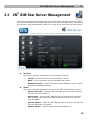
1
® 2N SIM Star User Manual Version SSS Version 1.9.0 1.9.0 www.2n.cz The 2N TELEKOMUNIKACE a.s. joint-stock company is a Czech manufacturer and supplier of telecommunications equipment. The product family developed by 2N TELEKOMUNIKACE a.s. includes GSM gateways, private branch exchanges (PBX), and door and lift communicators. 2N TELEKOMUNIKACE a.s. has been ranked among the Czech top companies for years and represented a symbol of stability and prosperity on the telecommunications market for almost two decades. At present, we export our products into over 120 countries worldwide and have exclusive distributors on all continents. 2N® is a registered trademark of 2N TELEKOMUNIKACE a.s.. Any product and/or other names mentioned herein are registered trademarks and/or trademarks or brands protected by law. 2N TELEKOMUNIKACE administers the FAQ database to help you quickly find information and to answer your questions about 2N products and services. On faq.2n.cz you can find information regarding products adjustment, instructions for optimum use and “What to do if...” procedures. Declaration of Conformity 2N TELEKOMUNIKACE a.s. hereby declares that the 2N® SIM Star product complies with all basic requirements and other relevant provisions of the 1999/5/EC directive. For the full wording of the Declaration of Conformity see the CD-ROM enclosed and at www.2n.cz. 2N TELEKOMUNIKACE company is the holder of the ISO 9001:2000 certificate. All development, production and distribution processes of the company are managed by this standard and guarantee a high quality, technical level and professional aspect of all our products. Table of Contents 1. Product Overview............................................................... 5 1.1 Product Overview ........................................................................................................... 6 1.2 2N SIM Star Components and Associated Products .............................................. 12 1.3 Upgrade and Innovations ............................................................................................ 15 1.4 New features in latest version..................................................................................... 16 1.5 Terms and Symbols Used ........................................................................................... 17 ® 2. Description and Installation ............................................ 19 2.1 System Component Description ................................................................................. 20 2.2 Before You Start ........................................................................................................... 25 2.3 System Component Installation .................................................................................. 28 3. 2N® SIM Star Server Configuration................................. 39 3.1 Web Interface ................................................................................................................ 40 3.2 Step-by-Step Basic Configuration .............................................................................. 45 3.3 2N SIM Star Server Management .............................................................................. 50 3.4 Gateways Menu ............................................................................................................ 61 3.5 GSM Groups Menu ....................................................................................................... 66 3.6 GSM Menu ..................................................................................................................... 68 3.7 SIM Boards Menu ......................................................................................................... 74 3.8 SIM Groups Menu ......................................................................................................... 78 3.9 SIM Menu ....................................................................................................................... 90 3.10 IMEI Menu ...................................................................................................................... 95 3.11 Rules Menu ................................................................................................................... 97 ® 4. Function and Use ........................................................... 101 4.1 SIM Card to GSM Module Assignment ..................................................................... 102 4.2 2N SIM Star Server Hot Swap .................................................................................. 103 4.3 How to Link Module IMEI and SIM Card IMSI .......................................................... 105 4.4 Prepaid SIM Card Credit Recharge ........................................................................... 106 4.5 Human Behaviour Functionality ............................................................................... 108 4.6 External API – SSS Uniclient Protocol ..................................................................... 111 4.7 2N SIM Star Server Tray SW .................................................................................... 112 4.8 External credit check/recharge script ...................................................................... 115 ® ® 5. Technical Parameters .................................................... 117 5.1 Technical Parameters ................................................................................................ 118 6. Supplementary Information .......................................... 119 6.1 Regulations and Directives ....................................................................................... 120 6.2 General Instructions and Cautions .......................................................................... 121 6.3 Troubleshooting ......................................................................................................... 123 6.4 Default configuration of Mikrotik RB750 .................................................................. 125 6.5 List of Abbreviations .................................................................................................. 128 1 1. Product Overview This section introduces the 2N® SIM Star product, outlines its application options and highlights the advantages following from its use. It also includes safety precautions. Here is what you can find in this section: Product Overview 2N® SIM Star Components and Associated Products Upgrade Terms and Symbols Used 5 Product Overview 1.1 1.1 Product Overview The 2N® SIM Star system is used for remote administration of the 2N GSM/UMTS gateway SIM cards. This solution helps you switch SIM cards in all of your gateways regardless of their locations comfortably from your office without travelling. It is because your distant 2N GSM/UMTS gateways do not contain SIM cards. Their SIM cards are installed on one site, thus avoiding potential misuse. 2N® SIM Star Features Financial and time cost efficiency due to elimination of physical exchange and credit recharge for your gateway SIM cards; Comfortable full SIM card control from your office; Central SIM card administration and location; SIM card misuse risk minimisation; Easy SIM card availability; Easy web interface based configuration; Up to 25,000 SIM card control; Human behaviour functionality (see chapter 4.5 on page 108); Possibility to use Domain name instead of IP addresses (less fixed IP addresses); Possibility to use API for adding new functionality by using 3rd party applications (see Subs. 4.6 on page 111). 2N® SIM Star is primarily designed for: SIM card and voice channel leasing companies; Network providers and alternative operators; Multiple GSM gateway (SIM card) administering companies. Safety Precautions It is prohibited to use any transmitters, including the UMTS/GSM devices connected to 2N® SIM Star, in areas where explosives are used, such as quarries. It is prohibited to use the GSM gateways connected to 2N® SIM Star at petrol stations where mobile telephones are also prohibited. GSM phones may affect sensitive life-saving devices in medical centres. Therefore, it is forbidden to use GSM/UMTS devices, including the GSM gateways connected to 2N® SIM Star, in such facilities. In general, any prohibition regarding mobile phones based on RF energy radiation applies to GSM/UMTS devices too. 6 Product Overview 1.1 If necessary, the GSM gateways connected to 2N® SIM Star may be installed at a safe distance from the prohibited area and connected with the original place through an Ethernet cable. Although GSM gateways are not intended for cars or aeroplanes, all relevant prohibitions and regulations regarding mobile phones apply to them too. Use Studies The figure below shows the basic components of the 2N® SIM Star system and indicates the independence of their installation sites. The solution includes a 2N® SIM Star Server unit, a SIM Board Box with one SIM Board at least and compatible GSM/UMTS gateways. Such gateways include 2N® StarGate, 2N® BlueStar, 2N® BlueTower and 2N® VoiceBlue Lite. 7 Product Overview 1.1 Human Behaviour Functionality The SIM Star system includes a lot of functions that can be configured in detail. These functions endow the system SIM cards with a behaviour that is close to that of a common mobile phone user. SIM travelling based on IMEI change, permanent/dynamic BTS lock and SIM login to gateways in various locations. Call limit functions based on watching the upper limits of called minutes and/or calls in defined intervals (mornings, afternoons, evenings, workdays, and weekends). Outgoing SMS limits in defined intervals. SIM credit monitoring and automatic recharging (USSD, SMS, IVR, and Call). Peak/off-peak low credit control. Automatic activation of a new SIM card and repeated activation on defined days or after defined actions (SIM recharge, e.g.). Minimum (random) relax time between two calls. Check of presence of alerting in outgoing calls. Reading of called free minutes according to the terminal network (own network, another network, PSTN, VPN). Automatic SIM card blocking in the system (failed calls, SMS, logins...). Simulated SMS and/or Call1 sending/receiving. SIM card recharge/activation disable options for selected modules. Temporary/Permanent automatic barring (Black list) of calls to numbers as defined in the user rules (unanswered, call length call, etc.).2 Enhanced SIM travelling – SIM IDLE time according to real distance between gateways (GPS position, up to three SIM card‟s moving speeds) 1 Enhanced CPU feature 2 External Routing Machine (ERM) feature 8 Product Overview 1.1 LAN Configuration The installation version shown in the figure below concentrates all the solution components in a single LAN. Investigating the figure more closely, you will find the communication signalling flows between the system components. The communication path between 2N® SIM Star Server, the SIM Board and the GSM gateway (via the CPU card) is marked green. The communication path between 2N® SIM Star Server and the SIM Client (i.e. a process running in the GSM gateway through the eCPU) is marked red. The communication channel between the SIM card and the gateway GSM module is violet. This solution represents the simplest version. Practically, however, the components are installed in more distant locations. SIM Board Box SIM Star Server StarGate CPU and SIM Board communication with 2N® SIM Star Server SIM Client communication with 2N® SIM Star Server SIM card and GSM channel communication GSM module communication with a GSM network (wireless) 9 Product Overview 1.1 WAN Configuration The solution in the figure below shows a configuration within an extensive WAN. The Internet is a good example. Together with the SIM Board, 2N® SIM Star Server is located in one LAN behind a router with the public IP address 1. Another LAN is in another location, including two GSM gateways supporting the 2N® SIM Star solution. The LAN router has the public IP address 2. A GSM gateway with the public IP address 3 is in another location. The two routers and the GSM gateway are connected to the Internet. The figure shows the communication channels between the components. This configuration requires a correct setting of the router and 2N® SIM Star Server for successful communication. Within the Internet, communication is routed to the public IP addresses and selected ports that are adapted to the corresponding IP addresses and component ports in the LAN. Remember to set the NAT tables for the IP Routers if used. IP Router before GSM Gateway IP port Service name Description 23 Telnet SSS access to Basic CPU (Control) 80 http SSS access to eCPU (Update) 1500 Telnet SSS Access to eCPU (SC control) 2222 Telnet SSS Access to Basic CPU (Update) IP Router before SIM Board IP port Service name Description 1500 Telnet SSS access to SB (Control) 10000-100031 Proprietary Stream of SIM cards IP Router before SIM Star Server IP port Service name Description 22 SSH Access for 2N Technical Support if necessary 80 / 443 http / http Access to SSS web interface 12346 Telnet LOG stream 12349 Proprietary IMSI distribution for Call/SMS Simulator 12350 Telnet API of SSS (Subject to licence) Tip The communication protocol responsible for SIM card transfer contains QoS information. Refer to the GSMs > View > Qos of SIM connection menu for current data. 10 Product Overview 1.1 VoiceBlue Lite SIM Board Box 2N® SIM Star Server Public IP address 3 Router 1 Public IP address 1 Public IP address 2 Router StarGate VoiceBlue Lite CPU and SIM Board communication with 2N® SIM Star Server SIM Client communication with 2N® SIM Star Server SIM card and GSM channel communication GSM module communication with a GSM network (wireless) 11 2N® SIM Star Components and Associated Products 1.2 1.2 2N® SIM Star Components and Associated Products The solution consists of the following five components: 2N® SIM Star Server, SIM Board Box, SIM Board, SIM Star GSM/UMTS Board a SIM Client. 2N® SIM Star SIM Board The SIM Board is a card designed for mounting in a SIM Board Box. Each of these cards is capable of accepting up to 32 SIM cards. 2N® SIM Star SIM Board Box The SIM Board Box is a chassis that contains the SIM Boards. Communication with 2N® SIM Star Server is ensured via a two-port Ethernet interface. 2N® SIM Star SIM Client The SIM Client transfers the information obtained from the 2N® SIM Star GSM/UMTS cards onto an Ethernet interface towards 2N® SIM Star Server. The SIM Client is part of the eCPU in the 2N® StarGate, 2N® BlueStar and 2N® BlueTower gateways and part of the gateway in 2N® VoiceBlue Lite. 2N® SIM Star GSM/UMTS Board The 2N® SIM Star GSM/UMTS Board is a card designed for 2N PRI and VoIP gateways. It replaces the existing GSM/UMTS boards in the gateways. This new solution provides interconnection with the SIM Client. 2N® SIM Star Server 2N® SIM Star Server is the core of the system. It communicates with all the key components and, as preconfigured, assigns SIM cards to the respective GSM gateway channels. Note For more information on the 2N® SIM Star components refer to S. 2 Description and Installation. 12 2N® SIM Star Components and Associated Products 1.2 Associated Products 2N® StarGate 2N® StarGate is the biggest of the 2N PRI GSM gateway family, enabling you to make up to 30 calls at the same time. In addition to ISDN PRI communication, the gateway also supports VoIP with SIP signalling. To use it within the 2N® SIM Star solution, use the enhanced CPU (eCPU) and make sure that the eCPU licence is valid. For detailed information on this product refer to the User Manual available on the 2N web sites. 2N® BlueTower 2N® BlueTower is the smallest of the 2N PRI GSM gateway family, enabling you to make up to 8 calls at the same time. In addition to ISDN PRI communication, the gateway also supports VoIP with SIP signalling. To use it within the 2N ® SIM Star solution, use the enhanced CPU (eCPU) and make sure that the eCPU licence is valid. For detailed information on this product refer to the User Manual available on the 2N web sites. 13 2N® SIM Star Components and Associated Products 1.2 2N® VoiceBlue Lite 2N® VoiceBlue Lite is a member of the small VoIP GSM gateway family, enabling you to make up to 4 calls at the same time. The gateway supports SIP signalling. To use it within the 2N® SIM Star solution, purchase a gateway with a special part number, which supports the 2N® SIM Star Server communication. 2N® VoiceBlue Next 2N® VoiceBlue Next is a member of the small VoIP GSM gateway family, enabling you to make up to 2 calls at the same time. The gateway supports SIP signalling. To use it within the 2N® SIM Star solution, purchase a gateway with a special part number, which supports the 2N® SIM Star Server communication. Note For more information on the GSM gateways refer to their respective manuals available on the 2N web sites. 14 Upgrade and Innovations 1.3 1.3 Upgrade and Innovations The manufacturer reserves the right to modify the product in order to improve its qualities. In response to the customers‟ requirements, the manufacturer constantly improves the software contained in the product (firmware). For the latest 2N® SIM Star Server firmware version and the User Manual refer to the 2N web sites. For a detailed description of the 2N® SIM Star firmware upgrade see the section devoted to the system installation. Manual Version Upgrade 3.0 The User Manual relates to the 2N® SIM Star Server firmware version 1.3.12-2616. 4.0 The User Manual relates to the 2N® SIM Star Server firmware version 1.4.0 5.0 The User Manual relates to the 2N® SIM Star Server firmware version 1.4.6rev2707 6.0 The User Manual relates to the 2N® SIM Star Server firmware version 1.4.7rev2720 7.0 Added Mikrotik RB750 default configuration 1.9.0 The User Manual relates to the 2N® SIM Star Server firmware version 1.9.0 15 New features in latest version 1.4 1.4 New features in latest version What’s new in v 1.9.0 (compare to 1.4.7) Updated GUI (dynamic rows in tables) Possibility to restrict maximum number of activated new SIM card / time / SIM group (see 3.8 page 78) Centralized SIM Star Server call simulator (see 3.8 page 78) Possibility to import different PIN code for each SIM card (see 3.7 page 74) Detection MSISDN number of SIM card in USSD answers (see 3.8 page 78) Possibility to deactivate unique control of IMEI number (see 3.10 page 95) Possibility to keep SIM card logged in afted credit recharge / SIM activation (see 3.8 page 78) More SIM card activations (SIM group) (see 3.8 page 78) Export / import SIM Star server database (see 3.3 page 50) Prioritization of SIM group (see 3.11 page 97) Support of Google maps (GPS position of GSM gateways) (see 3.4 page 61) New SW tool – Tray SW (see 4.7 page 1120 Support USSD menu (credit check, recharge) (see 3.8 page 78) Possibility to create/use external script (credit check, recharge) (see 3.8 page 78 and 4.8 page 115) Support of 16bit USSD answers (patch) Possibility to change hw position of SIM card without loosing SIM data Support of new OS CentOS 6 16 Terms and Symbols Used 1.5 1.5 Terms and Symbols Used Symbols Used in Manual Safety Warning Always abide by this information to prevent injury of persons. Warning Always abide by this information to prevent damage to the device. Caution Important information for efficient functionality. Tip Useful information for easy and quick use and programming. Note Routines and advice for efficient use of the device. Future Functions The grey-marked text in this document designates the functions that are under preparation or development at present. 17 2 2. Description and Installation This section describes the 2N® SIM Star product and its installation. Here is what you can find in this section: System Component Description Before You Start System Component Installation 19 System Component Description 2.1 2.1 System Component Description 2N® SIM Star SIM Board The SIM Board represents the main board for inserting SIM cards. Each SIM Board can accept up to 32 SIM cards. The card processor transfers the data obtained from the SIM cards onto an Ethernet interface. The SIM cards are used for communication via the IP ports ranging from 10000 to 10031 depending on their positions (can be reconfigured). IP port 1500 is used for the 2N® SIM Star Server communication. SSH port 22 provides direct access to the SIM Board. It is very important that all the ports are available to all the SIM Clients involved and 2N® SIM Star Server. Otherwise the system would be unstable or inoperative. The SIM Board is equipped with a CAN9terminated serial interface, which is used for the basic board IP settings. The card supports the „hot swap‟ function and can thus be removed and replaced if necessary without the SIM Board Box switch-off. 0 2 4 6 1 3 5 7 8 12 16 20 24 28 9 13 17 21 25 29 10 14 18 22 26 30 11 15 19 23 27 31 20 System Component Description 2.1 Front Panel The front panel includes three status LED indicators and a SIM Board default (factory) setting button. To restore the factory settings: 1) Remove the SIM Board. 2) Push the front panel button gently using a slim and blunt object. 3) Keeping the button pushed replace the SIM Board into the switched-on SIM Board Box. 4) Keep pushing the button for at least 20 seconds and then remove and replace the Board. SIM Board status indicators: PWR Indicates the SIM Board power supply. INIT Indicates the SIM Board initialisation. No light indicates a running SIM Board process. STAT Flashing indicates a running system. Caution SIM board 2012 has different HW layout! There is no SD card requied and it’s needs different firmware (included on latest SIM Star server) ! 2N® SIM Star SIM Board Box The SIM Board Box is a chassis that contains the SIM Boards. Each SIM Board Box can accept 1 to 18 SIM Boards with the maximum of 576 SIM cards. A front panel with two RJ45 ports is available for communication with 2N® SIM Star Server. The SIM Board Box works as an Ethernet switch and the cards are connected to it through a 10BaseT Ethernet interface. The two front panel ports help scale the SIM Board Boxes more easily. Each SIM Board has a unique IP address within the SIM Board Box. 21 System Component Description 2.1 2N® SIM Star SIM Client The SIM Client transfers information obtained from the GSM/UMTS cards onto an Ethernet interface towards 2N® SIM Star Server and vice versa. The SIM Client is an independent process running on the eCPU in the 2N® StarGate, 2N® BlueStar and 2N® BlueTower gateways and part of the 2N® VoiceBlue Lite gateway available under a special part number. SIM Client in eCPU The enhanced CPU (eCPU) card is an independent processor board for the 2N® StarGate/BlueStar/BlueTower gateways, extending the capabilities of the basic CPU. Its main advantages include a web configuration interface, SMS server, simulated calls and SMS messages as well as the SIM Client process, providing communication with the other 2N® SIM Star components. The SIM Client - 2N® SIM Star Server communication runs through port 1500. The SIM Client communication with the GSM gateway cards runs on the gateway main bus using the RS485 protocol. It is necessary for a successful eCPU – CPU communication that the IP addresses of the two interfaces are properly set and the interfaces are connected to the network. The modules communicate with the SIM Board SIM cards via ports 10000 to 10031, according to their positions in the gateway. Note For more information refer to the 2N® StarGate/ BlueStar/ BlueTower User Manual available on the 2N web sites. SIM Client in VoiceBlue Lite/Next The SIM Client is an integral part of the 2N® VoiceBlue Lite gateway. Enter the IP address and port 23 for communication with the CPU. Use the same IP address and port 1500 for communication with the SIM Client. The gateway modules communicate via ports 10000 through 10003. Set the processes that are necessary for a correct function of the SIM Client using the gateway configuration tool. Note For more information refer to the 2N ® VoiceBlue Lite User Manual available on the 2N web sites. 2N® SIM Star GSM/UMTS Board Board Description The GSM/UMTS board includes two GSM or UMTS wireless modules, PCM bus connection circuits, a DTMF receiver and, if the boards support 2N® SIM Star, a processor. The board is designed on a four-layer PCB of the size of 160x100mm. Pins 1 and 32 on the board system connector are approximately 1 mm longer and are used for the „hot swap‟ board function, which enables you to remove and replace the board under operation. This feature is particularly useful for the SIM card installation or 22 System Component Description 2.1 exchange. The front panel is equipped with two SMA antenna connectors and five system LED indicators. Module Types The 2N® StarGate/BlueStar/BlueTower GSM/UMTS gateways can use variable types of GSM or UMTS modules. The modules differ in the type of the wireless module used, the count of SIM card holders per module and also the 2N® SIM Star support (not all boards support this solution). The GSM/UMTS board types below can be used for the 2N® SIM Star solution. GSM card with 2 Cinterion MC55i engines, 1 SIM/channel; GSM card with 2 Wavecom Q55 (WPM100) engines, 1 SIM/channel; GSM card with 2 Wavecom Q55 (WPM100) engines, 4 SIM/channel (2012); UMTS card with 2 Sierra Wireless MC8795V engines, 1 SIM/channel. Note The GSM/UMTS boards can be blocked for specific networks. For more information refer to the 2N® StarGate/ BlueStar/BlueTower gateway User Manual. 2N® SIM Star Server 2N®SIM Star Server is the core of the system. It is composed of a Linux-based PC and web and database systems. It checks the channel statuses of the gateways connected with the main CPU (or VBL SS) via Telnet. 2N® SIM Star Server is connected to the eCPU SIM Client and the SIM Boards. The SIM card assignment obeys the predefined 2N® SIM Star Server rules and obtained status data on the main CPU GSM channels and SIM cards. Before a SIM card is assigned to a GSM/UMTS module, the SIM Client is notified and gets connected with the specific SIM card on one of the SIM Boards connected. The SIM Board is a passive component of the 2N® SIM Star system. 2N®SIM Star Server also synchronises all functional units integrated into the system and so set its time correctly to avoid any SIM card switching error. 2N®SIM Star Server can also assume control of module assignment to outgoing and incoming GSM groups, thus eliminating the need to make assignments in the gateways. 2N®SIM Star Server is also able to change the IMEI for some module types. This is particularly important for login of the SIM cards that are bound to a specific GSM module (are available together with the telephones). The following table sums up the main 2N® SIM Star Server functions for easy orientation. 23 System Component Description 1. Powerful SIM card switching; 2. Gateway time synchronisation and automatics upgrade; 3. PIN entering for SIM cards; 4. Incoming/outgoing GSM group control option; 5. IMEI change option for certain modules. 6. Fix or dynamic BTS lock; 7. SIM card credit check and automatic recharging; 8. Call & SMS simulation; 9. ASR and ACD monitoring and statistics; 10. Human behaviours functionality (see chapter 1.1, page 6) 2.1 The control communication between 2N® SIM Star Server, the SIM Client and the SIM Board runs on port 1500 through the Telnet protocol. The CPU communication also uses the Telnet protocol and runs through port 23. The SIM Client - SIM Board communication runs directly (without the participation of 2N® SIM Star Server) on ports 10000 through 10031. The port number determines the SIM card position in the SIM Board. 2N® SIM Star Server also uses the Telnet protocol for event log reports (port 12346) and for a specific interface for remote Call and SMS simulators on the eCPU (port 12349). An external API interface for 2N® SIM Star Server management is also available. For information on this interface refer to the SIM Server Management – Licence menu. The menu is available only if a licence supporting the external configuration is installed in the gateway. A web configuration interface is available for easy system communication. For details refer to the 2N® SIM Star Server Configuration section. 24 Before You Start 2.2 2.2 Before You Start Product Completeness Check Before installing this product, check whether the SIM Board Box delivery contains the items included in the following packing list: Package Pieces SIM Board Box 1 Two RJ45 port front panel 1 Power supply cable 1 Ethernet cable, 3m 1 SIM Board As ordered Installation Conditions The following conditions must be met for a successful system installation: Ensure a suitable location and enough free rack space. Allow free access to network elements. Provide a sufficient number of IP addresses, an appropriate bandwidth, an adequate response level and a minimum packet loss rate in the Ethernet network used. Use the recommended power supply with overvoltage protection and UPS back-up for all system components. Use 3V supplied SIM cards in the whole 2N® SIM Star system to avoid malfunction. Set one and the same PIN code for all the SIM cards in one SIM Board (or disable the PIN request) and make sure that the SIM cards are activated by the GSM/UMTS provider. You are recommended to install the system components in an air conditioned room. Note For more information on the GSM gateway installation conditions refer to the respective manuals available on the 2N web sites. 25 Before You Start 2.2 Warning Do not cover the top, bottom and rear sides of the gateway to avoid overheating and gateway error! Protection against humidity and extreme temperatures: The appliance may never be placed close to heat sources (radiators) or places exposed to direct sunshine. Also places with high humidity (such as bathrooms and cellars), places with significant temperature fluctuation (next to doors, windows), dusty places (workshops) and places exposed to aggressive gases (accumulator rooms, boiler rooms) as well as places with intensive vibrations and places exposed to shocks (compressor rooms, heavy industrial operations) should be avoided. . Caution If possible, place all the 2N® SIM Star components into one and the same network segment (without using the NAT). This version requires no profound knowledge of networks and active network element configuration. Licences All the 2N® SIM Star parts and functions are subject to licence. For an overview of the licences see below. GSM Gateways Relevant licences have to be installed for the gateways to work properly. To install a licence use the gateway configuration program. An active SIM Client licence has to be installed in the 2N® StarGate/ BlueStar/ BlueTower gateways for communication with 2N® SIM Star Server. Install the licence on the eCPU web interface. The SIM Client licence is part of the 2N® VoiceBlue Lite licence and installed through the gateway configuration interface. Note For more information on the GSM gateway licence conditions refer to the respective manuals available on the 2N web sites. 2N® SIM Star Server A licence including the CPU serial numbers (Mxxx-xxxxxxxxxx) of all the gateways connected has to be installed in 2N® SIM Star Server. Otherwise the server will not succeed in connecting to the gateway. In addition to a web interface, an external API interface can be used for the 2N® SIM Star Server communication too. This function is subject to licence. 26 Before You Start 2.2 2N® SIM Star Server allows for a change of the IMEI in the GSM modules that support this function. This function is subject to licence. Tip To install the 2N® SIM Star Server licence use the SIM Server Management – Licence file menu. 27 System Component Installation 2.3 2.3 System Component Installation 2N® SIM Star Step-by-Step Installation Guide 1. Set the required configuration for all the GSM gateways to be connected to 2N® SIM Star. 2. Set the Ethernet interface for the eCPU board and the SIM Client accordingly. Remember to install the relevant licence into the eCPU. 3. Connect all the CPUs and SIM Clients to the Ethernet network. It is recommended that all the components should be part of a single network segment. This version requires no profound knowledge of networks and active network element configuration. Note For more information on the GSM gateway configuration refer to the respective manuals available on the 2N web sites. 4. Put the SIM Board Box in operation. Insert the required SIM cards into the SIM Board, disabling the PIN request or enabling an identical PIN request for all the SIM cards in the 2N® SIM Star Server communication. If you fail to do so, your SIM card will not log in to the provider‟s network. Finally, insert the SIM Boards into the SIM Board Box positions. 5. Set unique IP addresses for the SIM Boards using a serial console and connect the SIM Board Box into the Ethernet network by connecting the network cable into the card front panel ports. 6. Install 2N® SIM Star Server as instructed in the 2N® SIM Star Server section. 7. Set the time and time zone for the 2N® SIM Star Server installation site. The time zone setting procedure is part of the installation process. 8. Set the 2N® SIM Star Server network interface. The DHCP is enabled by default. Connect 2N® SIM Star Server to the Ethernet network. 9. Use the web interface to log in to 2N® SIM Star Server as the administrator with the highest 2N® SIM Star Server configuration rights. For the login data refer to the Login section. 10. Set the appropriate IP addresses and communication for the GSM gateways, SIM Clients and SIM Boards. An automatic detection of the system components is available for easier setting as described in the Component Detection subsection. 11. Review the 2N® SIM Star Server date and modify it if necessary using the Date command. 12. Upload the relevant licence to 2N® SIM Star Server, including all GSM gateway serial numbers and providing the IMEI change and external API interface administration if necessary. 13. Set the SIM card switching rules as described in the Rules subsection. 28 System Component Installation 2.3 2N® SIM Star SIM Board Installation First, insert the SIM cards with the PIN request disable or identical PIN enable in the SIM Board. For the SIM card holder positions refer to the System Component Description subsection. Now insert the SIM Board in one of the eighteen SIM Board Box slots (positions). Each SIM Board must have a unique IP address. To view the IP address, use the console menu. Use a serial interface for connection to the SIM Board. For the connection parameters see below. Serial Console Access The console system is arranged as a set of nested menus. By selecting a menu item you either get into a submenu, or have the required operation executed, or set the selected parameter. Serial Link Settings Default parameters of the SIM Board serial connection: Item Value Baud rate 115,200bps Bits 8 Parity None Stop-bits 1 Flow control None Serial Console If the SIM Board is working properly, the main console menu gets displayed after the terminal is connected. To enter the main menu, push . If you select a submenu, the submenu gets displayed. Now you can select items from the selected submenu or push for return. The console menu is arranged as follows: Main menu The main menu is displayed after the cable is connected to the serial interface of the board. The main menu includes the following items: Configuration menu A menu for Ethernet interface, serial console and other parameter settings: 29 System Component Installation 2.3 o Network – use this item to configure the SIM Board Ethernet interface. Set a static IP address or enable the DHCP support. o Date and Time – set the date, time and NTP server address for the selected SIM Board. o SIM Star – set the username and password for the SIM Board login, the AT port for the 2N®SIM Star Server communication and the basic port for the SIM card communication ports. o Console – define the basic serial interface parameters. o Reset settings – reset the SIM Board default values. o Update password – set the SIM Board firmware update password. Privilege Use this option to define the user rights (Write/Read only). Help This item displays the Help. 2N® SIM Star SIM Board Box Installation The SIM Board Box requires no special installation. All you have to do is connect the power supply and Ethernet network cable to the front panel. The remaining positions are designed for the SIM Boards. 2N® SIM Star SIM Client Installation 2N PRI Gateway (eCPU) Solution A proper eCPU web interface configuration is necessary for connection to the eCPU web interface. For the steps refer to the 2N® StarGate / BlueStar / BlueTower User Manual. After the basic configuration, enable the SIM Client process in the Management menu if licensed. Complete the Settings for the SIM Client configuration. Username and Password Enter the username and password to be used by 2N® SIM Star Server for the SIM Client communication. The default value is 2n in either case. AT port Set the AT port to be used for the 2N® SIM Star Server - SIM Client communication. The default value is 1500. 2N® VoiceBlue Lite/Next Solution Set the gateway IP address for connection to the gateway configuration interface. For the 2N® VoiceBlue Lite configuration steps refer to the 2N® VoiceBlue Lite User Manual. The GSM gateway SIM Client is part of the gateway firmware and is always active. 30 System Component Installation 2.3 Note For more information on the GSM gateway configuration refer to the respective manuals available on the 2N web sites. 2N® SIM Star GSM/UMTS Board Installation One or four SIM cards can be assigned to each module and used whenever the 2N® SIM Star Server connection gets lost. Disable the PIN request or enable an identical PIN for the SIM cards as configured in the gateway. Each module is equipped with an SMA connector for antenna connection. The antenna should be connected before the SIM card is inserted. Warning Do not operate the module without connecting an antenna to avoid the module damage. Tip You are recommended to use an antenna splitter while connecting multiple antennas under good signal conditions (refer to the 2N® StarGate / BlueStar / BlueTower User Manual). 2N® SIM Star Server Installation PC Requirements 2N® SIM Star Server can be operated through a rack-mounted (or standard) PC with the minimum configuration requirements as shown in the Server Requirements table. The hardware requirements depend on the projected count of the SIM cards and GSM gateways. A 2GB RAM operational memory is. A monitor and a keyboard have to be connected to the PC for primary installation. Before installing the system (inserting the CD), set the CD booting option in the PC BIOS (change the sequence of the devices from which the system boots data). After installation, re-enable hard disk booting as the primary booting method to accelerate the system booting process. Tip You can enter the BIOS during the POST detection within a few seconds after the PC power on. To do so, use the combination of the + + or key, or a keys. 31 System Component Installation 2.3 OS Linux Installation Warning By using the 2N installation CD you remove all data from the PC hard disk! You are advised to download the latest CD image from the 2N web sites before installation, which, in addition to the 2N® SIM Star Server RPM package, includes a complete Linux installation program. Burn out the CD image onto a suitable disk. If you have set the CD booting method, insert the CD into the drive and power on/restart the PC to launch the process automatically. You will get the following screen: Now you can choose one of the available options. Automatic installation is listed first and, unless you choose another option within three seconds, will be launched automatically. After the basic system detections you will be asked whether you want to check the installation data CD data before installation. Select OK to confirm or Skip to continue. 32 System Component Installation 2.3 Now the hard disk is formatted automatically, a corresponding system of files is created and all necessary system components are installed. The automatic installation of all the system components takes about 30 minutes (according to the communication HW configuration). After installation, the installator awaits the system Reboot confirmation. Press to continue and then remove the CD from the drive. Now you have installed the Linux 32bit OS and associated 2N® SIM Star Server installation scripts and packages. Upon the system start, you will be invited to enter the login data. Local host login Admin Password 2n 33 System Component Installation 2.3 After login, the system setting wizard is launched as described below. System Settings Upon the primary login, you can set the time zone and 2N® SIM Star Server network interface using the wizard. Assign the static IP address including the network mask and the default gateway to the selected network interface, or enable the IP address obtaining from your network DHCP (default setting). If necessary, you can also use the wizard for setting the DNS parameters for your network. Having set all the required parameters, click on Save&Quit to quit the wizard. Now the network interface setting and database initialising processes follow. Do not interrupt the database initialising process to avoid database error and potential reinstallation. 2N® SIM Star Server Installation The installation process is launched automatically after the system setting and database initialisation processes are completed. The system will automatically install: 1. 2N® SIM Star Server 2. 2N® External Routing Machine Note For more information on 2N® External Routing Machine refer to the 2N® StarGate / BlueStar / BlueTower User Manual available on the 2N web sites. Now you can enter the 2N® SIM Star Server IP address into your web browser and display the web configuration login dialogue. For more information on the system configuration refer to the 2N® SIM Star Server Configuration section. 2N® SIM Star Server Firmware Upgrade You are advised to upgrade your system periodically to make the most of the system capabilities. For the 2N® SIM Star Server firmware upgrade procedure see below. Caution For the latest 2N® SIM Star Server firmware and User Manual versions refer to the 2N web sites. Use only the installation files certified by 2N to avoid lower functionality or even malfunction of the system! 34 System Component Installation 2.3 Upgrade via Web Interface Follow the steps below to upgrade 2N® SIM Star Server via a web interface. Prepare a RPM package with a new 2N® SIM Star Server version (SimStar-Server-x.x.x-xxxx.i386.rpm). Login as a user with Admin rights. Click on the SIM Server Management icon. Click on Restart in the left menu. Select the prepared RPM package using the Browse button and click on Restart. Wait for the automatic upgrade for a few minutes and then relog in. Caution 2N® SIM Star Server will be deactivated during upgrade! Remember to upgrade the back-up 2N® SIM Star Server version if available! Use only the installation files certified by 2N to avoid lower functionality or even malfunction of the system! In case of installation SSS in Hot backup mode – two running SSS – you have to make update both of SSS! Upgrade via SSH Interface Caution Use the SSH interface upgrade only in case the web interface method is not applicable! Upload the new firmware package to 2N® SIM Star Server using the WinSCP or a similar SFTP-based program. The transfer takes place through the SSH protocol. Run 35 System Component Installation 2.3 the program on your PC and log in to 2N® SIM Star Server through its IP address and port 22 using the following login data: Username Admin Password 2n Copy the firmware package into the /home/admin directory. Now move to 2N® SIM Star Server or get connected to it using the PuTTY or some other SSH client software. Enter the ls command to write out the current directory files, including your new firmware package. If the firmware package is not available, check whether you are in the correct directory and, if not, move to the correct one using the following command: cd /home/admin Enter the following command to open the package: rpm –Uvh file_name Now confirm the installation. Enter and click on . After the first firmware installation part, you will be asked whether you want to re-initialise the database. Think twice before doing so, because re-initialisation deletes the database completely. On the other hand, some system parts may be inoperative without database reinitialisation. After the whole installation process is completed, you will be asked whether or not to launch 2N® SIM Star Server. Enter and click on . A new firmware version has been installed successfully and you can get connected to 2N® SIM Star Server from your web browser again. Caution The database structure may be modified or configuration deleted during the 2N® SIM Star Server firmware upgrade and so re-create the database including all settings. The firmware upgrade results in a restart of all current SIM card – GSM module connections and may lead to a temporary system malfunction! The upgrade system is only allowed, downgrade will not be executed! Upgrade of Other 2N® SIM Star Components It may be necessary to upgrade other components of the 2N® SIM Star system too during the 2N® SIM Star Server upgrade process. This process does not run automatically for security reasons - must be initiated by the user. 2N® SIM Star Server automatically prepares the recommended firmware versions for other system components designed for the current 2N® SIM Star Server version. Download the files in the SIM Server Management > GW & SB/SC firmware > Support files folder. The folder also contains current versions of the User Manual and other useful utilities. 36 System Component Installation 2.3 Copy the system components into the preceding Firmware tag to execute the automatic upgrade. Refer to Subs. 3.3 – GW & SB Firmware for details. Caution The count of available system voice channels will be limited during the upgrade process! 37 3 ® 3. 2N SIM Star Server Configuration This section describes the 2N® SIM Star Server configuration. Here is what you find in this section: Web Interface Step-by-Step Basic Configuration 2N® SIM Star Server Management Gateways GSM Groups GSM SIM Boards SIM Groups SIM IMEI Menu Rules 39 Web Interface 3.1 3.1 Web Interface Essentials The 2N® SIM Star Server web interface supports the following web browsers: MS Internet Explorer v9.0 Mozilla Firefox v4 and higher Other web browsers may cause troubles. The recommended screen resolution is 1280x1024 and the colour quality 32bit or higher. The configuration interface is available in the English language only at present. Tip For better viewing, use the F11 key to launch the full screen mode. Login To log in to the 2N® SIM Star Server web configuration interface enter the 2N® SIM Star Server IP address into your web browser. The following login dialogue gets displayed: Tip Activate a simple login screen (in the case of system anonymity request) in the Management > Connections menu: 40 Web Interface 3.1 The users may log in with the following three types of privileges: Privileges o Admin – a user with the highest rights, authorised to manage configuration and the user accounts. o Edit – a user with the limited 2N® SIM Star Server configuration rights. o View – a user with the 2N® SIM Star Server configuration and log viewing rights. By default, one login name is created for each privilege: Login name Password Admin 2n editor p2 visitor p1 Caution You are recommended to change the default settings upon the first login to improve your system security. The system allows for concurrent logins of users with the configuration privileges. However, we do not recommend this because of a risk of erroneous saving of configuration data into the system database. 41 Web Interface 3.1 Home Page Upon your login, you get onto the Home page as shown below. There is a vertical list of menus on the left –hand side of the screen, which will be available to you in the horizontal format in every web configuration menu. You can see the user login name (administrator, editor, visitor) and privilege (Admin, Edit, View) in the right-hand upper corner. The Home page is the only screen where you can find the Logout button for user logout. After logout, you will be notified of your successful system logout and invited to close the browser window to avoid re-use of your login data. The main Home page field provides horizontally arranged icons representing the configuration menus. The links are logically grouped and have the same functions as the vertical menu items on the left. 42 Web Interface 3.1 Configuration wizards Configuration wizard pop up after the first system log in. This wizard can guide you through basic parameters of whole system or you can run for each logical part of system. You can use “Open wizard” link or wizard icon to run the wizard. This wizard will guide you through the basic parameters. Not all advance parameters are involved. Tip Wizard repeated pop up after each login can be activated/deactivated in user menu. Automatic Notification of Errors 2N® SIM Star Server can notify you of system errors if any. Select the errors to be notified in the SIM Server management >Connections menu. For example: Loss of GSM gateway / eCPU / SIM board connection Blocked SIM cards Low credit SIM cards; SIM cards not activated System test licence expiry is approaching Licence error in one of the GSM gateways connected Lack of free IMEI/recharge codes Low ASR, ACD of a 2N® SIM Star component 43 Web Interface 3.1 E-Mail Notification 2N® SIM Star Server supports automatic generation and transmission of alert e-mail messages in the event of errors as well as periodical sending of log files on system operation. Set the function for each user in the SIM Server management > User accounts > Settings menu. 44 Step-by-Step Basic Configuration 3.2 3.2 Step-by-Step Basic Configuration Tip We strongly recommend to use configuration wizards for first usage. This wizard will guide you through the basic configuration of 2N SIM Star server. The subsection provides detailed 2N® SIM Star Server configuration steps. The aim of the procedure is to log in one SIM Board SIM card to the network through a GSM module of the selected gateway. The procedure assumes that the other system components have been configured properly and deals with the 2N® SIM Star Server part only. 1. Log in to the web configuration interface as described in the Login subsection. 2. Upload the licence including the selected gateway serial number into 2N® SIM Star Server. To do so, use the SIM Server Management – Licence file menu. 45 Step-by-Step Basic Configuration 3.2 3. Move to the Gateways menu and add a gateway using the Add gateway item. Fill in all necessary data. Refer to the Add Gateway subsection for description of the items in the case of doubts. Once you have installed the licence and filled in the IP addresses, ports and login data, the GSM gateway will be marked as connected in the overview table. 4. Proceed to the GSM groups menu and add a group using the Add GSM group item. 46 Step-by-Step Basic Configuration 3.2 Tip Highlight the GSM / SIM groups by colour to make their listings clearer. Create new GSM / SIM groups simply by copying an already established group. Click on the button in the list of GSM/SIM groups. 5. Proceed to the GSM menu. Select your gateway in the filter. An overview of all gateway channels gets displayed. Click on Add in the last but one column in the row corresponding to the suitable position in the GSM gateway. Set a group for the GSM channel, fill in the other parameters if applicable and push Ok. 6. Proceed to the SIM Boards and add a SIM Board using the Add SIM Board link. Complete all necessary data. Refer to the Add Gateway subsection for description of the items in the case of doubts. If you have installed all parameters correctly, the SIM Board will be marked as connected. 7. Proceed to the SIM groups menu and add a group using the Add SIM group link. Complete all necessary data. Refer to the Add Gateway subsection for description of the items in the case of doubts. 47 Step-by-Step Basic Configuration 3.2 8. Proceed to the SIM menu. Select the added SIM Board in the filter and view the SIM cards in the corresponding SIM Board positions. However, these SIM cards have not been added yet. Click on Add in the SIM card row. Assign the SIM card to the SIM group created in the preceding step and set the required count of free minutes for the SIM card (or the available credit in the case of a prepaid SIM card). 9. Proceed to the Rules menu and add a rule using the Add rule link. Select your GSM group and the SIM group. Set the selection method for the SIM card to be assigned. Define the days and times for the rule. 48 Step-by-Step Basic Configuration 3.2 Tip If you work with time conditions frequently, use the Rules menu for facilitation. button in the 10. Now the SIM card should start logging in to the network through the GSM module. View the login process in the Status column of the GSM menu after filtering the added GSM gateway. Note When the SIM cards fail to log in to the GSM modules automatically, click on the failing GSM module / SIM card to check the GSM module / SIM card setting and state. Refer to the Lookup info menu for current data. 49 2N® SIM Star Server Management 3.3 3.3 2N® SIM Star Server Management This menu can be divided into two parts. On the left-hand side there are nine links to the menus described in the subsections below. The right-hand part offers overviews of the versions, times and database usage. For a view of the menu see the figure below. Versions This section provides information on the firmware versions: o Version – gives information on the firmware version. o Build – gives information on the firmware build version. o Database version – gives information on the database version, which defines the database structure. Times This section provides information on the on the 2N® SIM Star Server times. o Server local time – gives the 2N® SIM Star Server local time derived from the time zone defined. o Server GMT – gives the 2N® SIM Star Server time without time shift. GMT stands for the Greenwich Mean Time and is taken over directly from the BIOS. o Process uptime – gives the 2N® SIM Star Server process running time from the last power up/restart. o System uptime – gives the time from last OS power up 50 2N® SIM Star Server Management 3.3 Database usage This section helps monitor the use of the database, which limited to a certain extent. The first column includes the items to be monitored. The second column shows the currently used items of the maximum count of the database items concerned. The third column shows the percentage of use and the last column expresses the use graphically. SIM Server About The menu provides essential contact information on 2N TELEKOMUNIKACE a.s. You will find here the address, telephone and fax numbers and e-mail address of the Sales Department and Technical Support as well as a link to the 2N web sites. This section also contains HW PC information Caution To prevent potential problems with SSS functionality please use HW PC according to minimal HW requirement! SIM Server Load The menu uses a graph to show the server load in time. The load can cover the past 300 seconds, 300 minutes or 300 hours, or a combination of these values. Press F5 to refresh the screen data. Moreover, the ASR and ACD graphs for the whole 2N® SIM Star Server system are displayed including the last three day / two week / six month history. The displayed data are for information only! Use the Settings folder to define which types of records should be periodically stored and subsequently displayed in the forms of graphs. Licence File Some 2N® SIM Star Server functions and GSM gateway connections are subject to licences. To manage the licences use this menu. 51 2N® SIM Star Server Management 3.3 Current licence limitations Check whether your current licence includes the following two system functions: o IMEI change support – some GSM board types are able to change their IMEIs according to the 2N® SIM Star Server requirements. This function is subject to licence. o External configuration – this function is used for the external 2N® SIM Star Server configuration via the API interface. If enabled, the menu provides a link to the documentation. o BTS lock support – only modules SierraWireless Q55, Q24CL and Q2400 supports BTS lock feature! This feature is licenced. Licenced gateways The section displays a list of serial numbers of all the GSM gateways that may be used with 2N® SIM Star Server. 2N® SIM Star Server cannot be connected to gateway types other than those listed here. Every record also includes information on the licence expiry. Upload new licence file The section helps you upload a new licence file. Select the file location using the Browse button and push Upload licence file. GW & SB/SC Firmware Since 2N® SIM Star Server communicates with all the system components, the components may be upgraded remotely by 2N® SIM Star Server. 2N® SIM Star Server automatically distributes the latest firmware upgrades to all the required devices, thus eliminating the need to modify the components separately. Use the Component version review link to move to a page showing the current software status in each system component. Current firmware The section provides a full survey of the current software versions for the selected components. You can replace or delete the firmware data. o SB/SC card – gives the current software version for the SIM Board and SIM Client. o SB/SC root – gives the current Linux version for the SIM Board and SIM Client. o eCPU firmware – gives the current firmware version for the eCPU. o SB v2 firmware – gives the current firmware for the SIM board cards version Y2012 (doesn‟t contains normal size SD memory card holder) o SG/BS/BT firmware – gives the current firmware version for the 2N® StarGate/BlueStar/BlueTower gateway CPUs. 52 2N® SIM Star Server Management o VBL firmware – gives the current firmware version for the 2N® VoiceBlue Lite gateways. o VBN firmware – gives the current firmware version for the 2N® VoiceBlue Next gateways. 3.3 Upload new firmware file This section helps you upload the current firmware to 2N® SIM Star Server for automatic distribution to all available components of the given type. You can save the FW versions and auxiliary SW tools from the Support files folder for future upgrade of the system components. Caution The firmware upgrade results in a restart of some devices on which the remote firmware restarting process is taking place. This process has a temporary effect on the system function. User Accounts This menu helps you edit the 2N® SIM Star Server user accounts, change the privileges and access passwords. Logged user Use this section to change the data related to the currently logged-in 2N® SIM Star Server user. o Change password – change the user password. The random password generating function is also available. o Settings – change the user e-mail address and enable/disable sending alerts. o User name – the currently logged-in user‟s name is displayed. o Privileges – the currently logged-in user‟s privilege is displayed. User table The table provides a list of the current 2N® SIM Star Server users. o User name – displays the username. o Privileges – displays the user‟s privilege in the system. o E-mail – displays the user‟s currently available e-mail. This item is necessary to sending automatics e-mail alerts o Alerts – displays whether sending of e-mail alerts is enabled for the selected user. o Add new user – use this item to add a new system user with a specific privilege. o Change password – use this item to change the selected user‟s password. o Settings – use this item to change the user‟s e-mail address and enable/disable sending of alerts. o Remove – use this item to remove a user from the system. 53 2N® SIM Star Server Management 3.3 Note Make sure that the SendMail component is set properly in the Linux OS to ensure correct e-mail alert sending. Logger Logger The menu provides a view LOG records in 2N® SIM Star Server. The records are marked with a timestamp. Define which events should be recorded automatically in 2N® SIM Star Server in the Log settings folder. Display the list of events arranged according to the date in the Log list. Tip To view the log on-line, get connected to the 2N® SIM Star Server IP address on port 12346 using the Telnet protocol. The login data are identical with the web interface login data. You can activate the automatic log file e-mail sending option in the user settings. 54 2N® SIM Star Server Management 3.3 CDR (Call Data Records) 2N®SIM Star Server is able to store automatically call data records (CDR) from all available GSM gateways. Download the CDR using this menu. Download CDR from gateways Use this parameter to enable downloading and saving call records from all the gateways connected. To change the setting click on Apply. Save downloaded CDR to file Use this option to save the call records available on the 2N® SIM Star Server disk into a local disk file. Push the Save button to create a cdr.zip package to be saved. Clean downloaded CDR Use this option to delete all current call records on the 2N® SIM Star Server disk. After pushing the Clean button you will be asked for confirmation and the records will not be deleted until you confirm the operation. Component Detection Use the menu for an easy detection of devices within one network segment. Upon your primary entering (and upon every deletion of the detection results), the Start>> button is only available for proceeding to the detection setting page. Component selection Here specify the devices to be detected in the selected network segment. Choose GSM gateways, SIM Boards or both. Network range The maximum possible count of IP address and port combinations for searching is 10,000. o IP range – set the IP address range to be searched in the selected network segment. By leaving the last field blank you initiate searching on a specific IP address with variable ports. 55 2N® SIM Star Server Management o 3.3 Ports – set the ports or port range for network segment searching. The ports are separated with a comma, the port range is entered with a dash (e.g. 23,1500-1502). Ports 23 and 1500 are entered by default. GW setting You have to log in to a gateway to verify whether the gateway is connected on the selected IP address. To do so, fill in the username and password here. This searching method is ineffective if the gateways to be detected have different login data. (default username/password = Admin/2n) SB & SC setting You have to log in to a SIM Board to verify whether the SIM Board is connected on the selected IP address. To do so, fill in the username and password here. This searching method is ineffective if the SIM Boards to be detected have different login data. (default username/password = 2n/2n) Detection Results Network segment searching combinations are compiled according to the settings. The course of detection is signalled graphically and numerically. To discontinue detection any time push the Stop button. Three buttons are available after the detection is completed: Start>> Push the button to return to the detection setting page. Clean Push the button to delete all the existing detection results. Result>> Push the button to display the detection results. Now you can add the detected system components to the 2N® SIM Star Server configuration. Before doing so, assign the SIM Clients to the corresponding GSM gateways as they are detected as independent components and their links cannot be defined by 2N® SIM Star Server alone. You can assign them individually or collectively. The GSM gateways with the SIM Clients and the SIM Boards are added separately. The figure below shows a potential detection result where one gateway, one SIM Client and one SIM Board have been found. This solution represents the simplest available configuration. 56 2N® SIM Star Server Management 3.3 The detected setting of a device behind the NAT server may be wrong due to the Network Address Translation. Such records are included in the NAT column and should be verified. Some detected SIM Boards or SIM Clients are indicated with an exclamation mark. It means that 2N® SIM Star cannot verify whether the device is a SIM Client or a SIM Board or any other component. Restart Use this option to restart 2N® SIM Star Server. After pressing the button, you will be asked for confirmation and only then the system will be restarted. You can also execute an automatic 2N® SIM Star Server upgrade here. Refer to Subs. 2.3 - 2N® SIM Star Server Firmware Upgrade for details. You can also make export/import of 2N® SIM Star Server‟s database and set-up 2N® SIM Star Server mirroring (hot backup) – see page 103, section 4.2. 57 2N® SIM Star Server Management 3.3 Caution Restarting 2N® SIM Star Server may discontinue the currently running calls and result in a temporary system malfunction! Make sure that automatic upgrade is applicable before restarting! For example, automatic upgrade is impossible upon transition from version 1.3.x to 1.4.0 via a web interface and upgrade via a SSH interface is necessary! Connections Server ID Custom name of 2N® SIM Star Server used for web interface and e-mail alerts. Server link 2N® SIM Star Server custom link for easy access by direct links from e-mail alerts. Delay for e-mail alerting Minimal delay between two last e-mail alerts. ASR/ACD threshold for alerting Defines minimal good level of ASR to send e-mail alert. Licence expiration for alerting Minimum number of days to send automatics alert e-mail to prevent SSS stop due to expired licence. Low number of IMEIs/recharge codes Define minimum unassigned/unused items to send automatics alert e-mail to prevent potential problems. 58 2N® SIM Star Server Management 3.3 Auto logout (min) Automatic logout time due to user inactivity. IMSI/Phone distribution The links defined between the SIM card IMSI (International Module Subscriber Identity) codes and the phone numbers used by 2N® SIM Star Server can be shared by other applications too. By activating this parameter you make the linking information available on UDP port 12349 on the 2N® SIM Star Server IP address. To confirm the setting changes click on Apply. Use Telnet Router Enable connection of the JAVA applet terminals using IP port 12352. This function is necessary if the device is located behind the NAT. Caution By activating this function you lower the security level of the whole system! Simple login form This option helps you use the anonymous style of the 2N® SIM Star Server login page. Admin This section helps you monitor the currently logged-in web configuration interface users through a login table with the following columns: o Status – shows the current login status. o Remote address – gives the address from which the user logs in to 2N® SIM Star Server. o User – gives the user login name. o Privileges – specifies the logged-in user privilege (Admin, Edit, and View). Caution A single user should edit 2N® SIM Star Server at one moment (administrator or editor) to avoid unintentional configuration rewriting. External Admin This section helps you monitor the currently logged-in API users through a login table with the following columns: o Status – shows the current login status. o Remote address – gives the IP address and port from which the user logs in to 2N® SIM Star Server. o User – gives the user login name. o Privileges – specifies the privilege of the logged-in user (Admin, Edit, and View). Logger This section helps you monitor the currently logged-in users viewing the 2N® SIM Star Server log. All created users may view the log independently of their rights. The login table includes the following columns and functions: 59 2N® SIM Star Server Management 3.3 o Status – shows the current login status. o Remote address – gives the IP address and port from which the user logs in to the 2N® SIM Star Server log interface. o User – shows the user login name. o Disconnect – is used for forced termination of the current log interface connection. The Admin user is the only to terminate such connection. Session lock The Lock button enables an Admin user to lock the other users‟ access. The lock is valid for the user‟s login time. As soon as the user logs out or the user‟s login timeout expires (due to inactivity), the connection is released for other users. If multiple Admin or Edit users log in to 2N® SIM Star, they are notified of this fact and should not make any changes in the configuration. Autologin by web session Function to save access cookie to your web browser which enables you automatics login without username/password. This feature is comfortable with using e-mail alert direct links. Caution This feature cause potential security risk. Please use it only on secured PC and web browser. This feature doesn‟t works with web browsers in anonymous mode. 60 Gateways Menu 3.4 3.4 Gateways Menu The menu enables you to get an overview of the GSM gateways, add new gateways and modify the gateway settings. Add Gateway Use this function to add new GSM gateways to the configuration manually. You can use the following parameters for adding: General info Here set the essential data on the gateway to be added. o Description – the text facilitates gateway identification only (GW Prague, e.g.). o GSM count – the count of channels or the type of the gateway to be added. o Time zone – the time zone for the gateway location. 2N® SIM Star Server automatically sets time for all the gateways connected and so this setting influences the time-dependent SIM card switching. Gateway position – Physical position of a GSM gateway. Used for feature “Advanced SIM card movement” o GPS latitude o GPS longitude GW network info Here fill in the information related to the gateway CPU network interface and login data. o IP – enter the CPU Ethernet interface IP address of the GSM gateway to be added. This IP address is included in the System parameters menu in the gateway. o AT port – define the port to be used for the 2N® SIM Star Server – gateway CPU communication. By default, this port is 23 (TCP), but the value can be changed if the NAT is used. o Username and Password – enter the username and password for the gateway login and update. These settings can be changed in the Login account menu in the gateway only if a serial interface is used for connection. Default username / password are Admin/2n. o Update port – define the port to be used for automatic gateway firmware update. Port 2222 is used by default. The setting can be changed in the System parameters menu in the gateway. While using the NAT or firewall, remember that the UCMD protocol based on the UDP transfer is used for update. o Conn. timeout (s) – set the automatic report timeout in the case of unavailability of the device. 61 Gateways Menu 3.4 SC network info Here fills in the information related to login to the gateway SIM Client. o IP – enter the IP address on which the gateway SIM Client is running. The address is the eCPU address for the 2N® StarGate / BlueStar / BlueTower gateways and the CPU address for the 2N® VoiceBlue Lite /Next gateway. o AT port – define the port to be used for the 2N® SIM Star Server – gateway SIM Client communication. The default port is 1500 (TCP), but the value can be changed if the NAT is used. o Username and Password – enter the username and password for the SIM Client login. These settings can be changed in the eCPU web configuration interface. Default values are 2n/2n o Update/web port – define the port to be used for automatic eCPU firmware update through the web interface using the http protocol. Port 80 is thus used by default. This option is inapplicable in the 2N® VoiceBlue Lite gateway as the SIM Client is part of the gateway firmware. o Update password – enter the 2N® SIM Star Server user password for the eCPU. This option is inapplicable in the 2N® VoiceBlue Lite gateway as the SIM Client is part of the gateway firmware. o Conn. timeout (s) set the automatic report timeout in the case of unavailability of the device. o SIM cache – select the type of SIM card communication. If there are only UMTS SIM cards (USIM) on the selected SIM Board, the recommended option is UMTS only. - Do not change setting – retain the factory values from the SIM Board setup. - GSM and UMTS – the GSM SIM card protocol is used and, if unsuccessful, the UMTS protocol is used for SIM card initialisation. - GSM only – the GSM SIM card protocol is only used for SIM card initialisation. - UMTS only – the UMTS SIM (USIM) card protocol is only used for SIM card initialisation.. - Turn cache off – select this option to debug SIM card initialisation. This option disables all SB – SC protocol optimisations and sets higher data flows between the systems! Caution Setting SIM cache to values other than the factory settings may result in a higher error rate during SIM card login to GSM networks, or even a complete communication failure! Call Simulation – Maximum channels – Maximum number of GSM channels used for virtual call simulation in one time. 62 Gateways Menu 3.4 New GSM default settings This section enables you to make basic pre-settings for the gateway GSM channels automatically. o Use default settings for new GSM – enable the use of the following three GSM channel adding parameters. If this option is not selected, the parameters are not applied. Nevertheless, if any of the following parameters is enabled, this option is selected automatically. o GSM Group – automatic assignment of GSM channels to the selected GSM group. o Remark – a note for easier orientation in the configuration. o Disabled – disable the use of the selected gateway channel. Add GSM now o Add all GSM – select this option to automatically add all the detected gateway GSM channels to the 2N® SIM Star Server configuration. Overview Table The section provides a table overview of all the gateways connected. Tip Dark grey column indicates columns with changeable content. By clicking on it you can change content of table. Columns o Id – shows a unique identification number for each gateway in 2N® SIM Star Server. o Description – describes the gateway for easier identification. The descriptions may be identical for variable gateways. o Gateway status (Gateway IP:port) – displays the current gateway connection (CPU) status. o SIM Client status (SIM client IP:port)– displays the current SIM Client (eCPU) connection status. o GSMs – active link to the GSM/UMTS module status list for the GSM gateway connected. o Action icons View – display the current GSM gateway state and setup. Edit – edit the GSM gateway setup. Remove – delete the GSM gateway from the 2N® SIM Star system. 63 Gateways Menu 3.4 Action menu – used for manual reconnect with the GSM gateway/SIM Client, by opening on-line GSM gateway / module state monitoring windows. Tip Action menu contains options “Open GW/GSM watcher” which show online state of gateway/GSM modules. Action menu contains option “View in Google Maps”. If you define GPS position of GSM gateways. You can see position of it on real maps. Multiselection – use this button to select a higher number of items for a global change. Buttons o Select all – push the button to mark all the GSM gateways at once. o Unselect all – push the button to cancel the Select all function. o Remove selected – push the button to remove the gateways from configuration that are selected in the last overview table row. Tip If a working gateway is designated as disconnected, check the IP address, port and password settings in the GW and SC network info sections. The GSM gateway overview window includes the following tags: GSMs – link to the GSM/UMTS module state overview for the GSM gateway selected. Edit – edit the selected GSM gateway. Remove – delete the selected GSM gateway. Action menu for manual reconnect with the GSM gateway/SIM Client, by opening on-line GSM gateway / module state monitoring windows. ASR, ACD graph – 2N® SIM Star Server can save and subsequently display the ASR and ACD data on the entire GSM gateway system connected. If the displayed data are discrete, the GSM gateway has been disconnected. The displayed data are for information only! Open PRI gateway configuration in new window – web link to the eCPU web interface. 64 Gateways Menu 3.4 Open VoiceBlue Next configuration in new window – web link to the web interface of 2N® VoiceBlue Next connected. Other Controls Description filter The filter is used for searching GSM gateways according to the data included in the Description field. Any part of the string can be used for searching. To cancel the filter click on Unset. Component detection This is a link to the system component detecting menu. For the menu function refer to the Component Detection section. 65 GSM Groups Menu 3.5 3.5 GSM Groups Menu The menu helps you add, edit and view the GSM groups. Tip Highlight the GSM / SIM groups by colour to make their listings clearer. Create new GSM / SIM groups simply by copying an already established group. Click on the button in the list of GSM/SIM groups. Add GSM Group Use this function to add new GSM groups to the configuration manually. General info o Description – type a text to be used for easier orientation in the configuration. o Highlighting – select the user colour codes for easier group listing. Gateway routing – set the outgoing/incoming group for the LCR table of the GSM gateway whose modules are assigned to the selected GSM group. The following priorities are respected: 2. SIM group (SIM card) setting; 3. GSM group (GSM module) setting; 4. User setting in the GSM gateway. o Outgoing group – select the outgoing group for the GSM gateway LCR table. o Incoming group – select the incoming group for the GSM gateway LCR table. Recharging and activation – use this item to control the SIM card activation and recharging for the GSM modules of the selected GSM group. BTS lock – if the GSM modules in the selected GSM group support the BTS lock and the function licence is valid, 2N® SIM Star Server will send information on the required BTS to the gateway upon every GSM module login, i.e. upon every outgoing call. o BTS lock type – select the BTS type for GSM module locking: Use the assignment table – the GSM modules will use the BTS as specified in the table below the selection. Use random available BTS for each call – a different, randomly selected BTS with a signal level above the Minimum signal level value will be used for each new outgoing call. 66 GSM Groups Menu o MCC+MNC – network code for the selected BTS Id. o BCCH Freq – BTS code. 3.5 Caution The GSM group assignment settings affect the call routing process in the GSM gateway connected. Therefore, leave the default parameters unchanged if in doubts. If BTS is set incorrectly, the GSM module will be blocked and unable to log in to GSM/UMTS! Tip We recommend you to use the 2N BTS Lock SW for finding the BTS Id. Connect the SW to a remote GSM gateway using the Telnet protocol and display the available BTS. Refer to the Management >GW & SB/SC firmware > Support files menu for this utility. Overview Table The section provides a table overview of all available GSM groups. Columns o Id – shows a unique identification number for each GSM group in 2N® SIM Star Server. o Description – describes the GSM group for easier identification. The descriptions may be identical for variable GSM groups. Functions View - displays current information on the selected GSM group o Edit – helps modify all the parameters mentioned in the o Add GSM Group section. o Remove – deletes a GSM group from the 2N® SIM Star Server configuration. Copy – copy settings of selected GSM group to new one. o o Multiselection – use this button to select a higher number of items for a global change. Buttons o Select all – push the button to mark all the GSM groups at once. o Unselect all – push the button to cancel the Select all function. o Remove selected – push the button to remove the GSM groups from configuration that are selected in the last overview table row. 67 GSM Menu 3.6 3.6 GSM Menu The menu is used for GSM channel administration. You can add, remove and edit the GSM modules and view the SIM cards assigned to them. Add GSM Tip Dark grey column indicates columns with changeable content. By clicking on it you can change content of table. The GSM channel is always associated with a gateway and its GSM module. To add a GSM channel use the Add item in the overview table, which is available to unassigned modules only. General info o GSM group – defines a GSM group for the GSM channel to be assigned to. It is unnecessary to select a GSM group. o Remark – description of the GSM channel for easier orientation in the configuration. o Disabled – here you can temporarily disable the module use. o SIM card testing – use this option to switch the GSM channel into the SIM card testing mode. In this mode, no restrictions apply to the SIM card. The testing modules are marked green in the listing. Tip The testing modules are marked green in the overview. This option is recommended for manual SIM card testing by the 2N® SIM Star system service staff (credit, voice quality, etc.). Hard linked SIM The section enables fixed assignment of a SIM card to the selected gateway GSM module. o Select SIM Board – select the SIM Board where the selected SIM card is located. o Select SIM card – select a SIM card from the selected SIM Board. 68 GSM Menu 3.6 Overview Table The section provides a table overview of all available GSM channels. Columns o Id – shows a unique identification number for each GSM channel in 2N® SIM Star Server. o Channel – shows the number of the GSM gateway channel for easier identification. o Group – shows assignment to a GSM group. o Status – displays the current GSM channel status. o IMEI sup. – shows whether the selected channel supports IMEI change or not. o BTS lock – shows whether the selected channel supports BTS lock function. o Actual SIM – displays the SIM card currently assigned to the GSM module. o Hard SIM – provides information on hard SIM card assignment to the GSM module. o Remark – a note related to the selected GSM module. o Disabled – disables the GSM module use temporarily. Functions o View – displays current information on the selected GSM channel (see below). Edit – helps modify all the parameters mentioned in the o Add GSM Group section. o Remove – deletes the selected GSM channel. After removal, the channel will be marked as unused. Action menu – select one of the following actions: o Reset – restart the selected GSM/UMTS module; Log out – log the SIM card out of the selected GSM/UMTS module. Buttons o Select all – push the button to mark all the GSM channels at once. o Unselect all – push the button to cancel the Select all function. o Select GSM with given status – an extended option for mass marking of GSM channels in a specific status. The status is selected in the field next to this item. o Unselect GSMs with given status – an extended option for cancelling of mass marking of GSM channels in a specific status. The status is selected in the field next to this item. o Edit selected – push the button to edit the selected GSM modules. 69 GSM Menu 3.6 o Remove selected – push the button to delete the assignments of the selected GSM channels. o Reset selected – push the button to restart the selected GSM channels. o Add selected with default settings – push the button to add all the selected GSM channels with default settings. o Add selected ignoring default settings – push the button to set the basic parameters as described in the Add GSM section before mass adding. View GSM x Click on to open the GSM module status page: General info o Gateway – name and Id of the GSM gateway in which the selected GSM/UMTS module is located. o Channel – Id of the channel assigned to the selected GSM/UMTS module. o GSM group – Id and name of the 2N® SIM Star Server GSM group to which the selected GSM module is assigned. o Remark – an optional user name for the GSM module. o Disabled – information on whether the GSM module is enabled/disabled for pairing with SIM cards. o SIM card testing – information on whether or not the GSM module has been switched into the testing mode. GSM status info o Status – status of the selected GSM/UMTS module (red means an error). o Error - not used o Start flag – not used o IMEI change support – information on whether or not the selected module supports the IMEI change (subject to licence). o BTS lock support – information on whether the selected module supports the BTS lock (subject to licence). o Logged IMSI – IMSI of the currently logged-in SIM card. o Actual IMEI – current module IMEI. o Original IMEI – factory IMEI. o SIM type – type of the currently connected SIM card. o Call limit (min) – maximum count of called minutes for the SIM card logged. o Call limit (count) – maximum count of calls for the SIM card logged. o SMS limit – maximum count of outgoing SMS for the SIM card logged. o Logged limit (min) – maximum SIM card login time. 70 GSM Menu 3.6 o Minimum credit – minimum SIM card credit for successful calls. o Call minutes – count of minutes already called. o Call count – count of outgoing calls already made. o Failed call count – count of unsuccessful calls. o Failed successive calls – count of unsuccessful successive calls. o SMS count – count of outgoing SMS. o Failed SMS count – count of unsuccessfully sent SMS. o Failed successive SMS – count of unsuccessfully sent successive SMS. o Logged minutes – SIM card login time. o Current credit – current SIM card credit value. o Call duration sum – total call time. o AoC settings – AoC pulse settings. o BTS lock – BTS lock options: active, inactive, type. o BTS status – BTS lock status. QoS of SIM connection – current communication state between the SIM card (SIM Board) and the GSM module (SIM Client). o Send packets – count of successfully sent packets. o Repeated packets – count of packets that had to be sent repeatedly. o Received packets – count of successfully received packets. o Min resp. time (ms) – minimum time between packet sending and packet receiving confirmation. o Max resp. time (ms) – maximum time between packet sending and packet receiving confirmation. o Avg. resp. time (ms) – average time between packet sending and packet receiving confirmation. Caution An excessively high number of repetitions and/or long response time indicate a poor IP connection between the GSM gateway and the SIM Board(s). A low QoS value may extend the SIM card logging time or even block the SIM card login! Assigned SIM card info – current information on the SIM card logged. o Actual SIM – IMSI of the currently assigned SIM card. o Hard assigned SIM – IMSI of the permanently assigned SIM card. GSM call info – information on the state of call parameters: o Call status – current module status. o Channel from – number of the channel from which the call was transferred to the GSM module (not used for VoIP calls). o Channel to – number of the GSM module within the GSM gateway. 71 GSM Menu o Dial – called number. o Duration – active call time. 3.6 GSM signal info o Level - current signal level. o Network – Id of the network to which the GSM module is logged in. ASR – information on the ASR module with the current and preceding SIM card. ACD – information on the ACD module with the current and preceding SIM card. Lookup info – current module status as viewed by 2N®SIM Star Server. Tip The information included in the Lookup info menu can help you identify and resolve the GSM module/SIM card assignment problems if any. Lookup info is offered by both the GSM module and the SIM card. Other Controls Filter Views Show gateway Filter the GSM channels according to their assignments to a GSM gateway. Show GSM group Filter the GSM channels according to their assignments to a GSM channel group. Show positions Filter the GSM channels according to the used/unused positions in the GSM gateway. View Table This menu helps you choose how to view the selected GSM/UMTS modules and their states. Basic table – basic view as described above. View calls of listed GSM – current list of calls via the selected GSM/UMTS channels: o Call status – current call status of the GSM channel. o Channel from – the channel through which the call comes into the GSM gateway. o Channel to – the channel through which the call goes out of the GSM gateway. 72 GSM Menu o Dial – called number. o Duration – duration of a call through the given GSM channel. 3.6 View signal of listed GSM – digital and graphical view of the current signal intensity and the name of the GSM/UMTS network where the selected module is currently logged in. ASR/ACD of listed GSMs – current ASR/ACD values for the selected GSM/UMTS modules. Information about logged SIM cards – a well-arranged list of current ASR/ ACD values and SIM card credits / remaining minutes. CDR (Call Data Records) Transition to the CDR (Call Data Records) menu in the Logger menu in the 2N® SIM Star Server Management Menu section. For details refer to the Logger menu above. 73 SIM Boards Menu 3.7 3.7 SIM Boards Menu The menu enables you to get an overview of the SIM Boards, add new SIM Boards and modify the SIM Board settings. Add SIM Board Use this option to add another SIM Board manually. General info o Description – the text is for easier identification of a SIM Board only. SB network info o IP – local IP address of the SIM Board for 2N® SIM Star Server - SIM Client communication within one and the same or local network. o IP 2 – public IP address of the IP Router (if different from the local IP address) for 2N® SIM Star Server/SIM Client located in another IP network. o AT port – the port to be used by 2N® SIM Star Server for communication with the SIM Board. The port is set to 1500 (TCP) by default but can be changed in the SIM Board console menu when a serial link is used. o SIM base port – IP port of the first SIM card on the SIM Board (32nd SIM uses the SIM base port + 31 = default 10031) for SIM Board - SIM Client communication within one and the same IP network. This information is essential for a correct SB - SC communication. To change the port range for the virtual channels use the SIM Board console menu when a serial link is used. Caution If the SIM Board is connected behind the IP Router, set a correct IP port routing in the NAT table for the router: SIM base port + 31 (default 10000-10031) for SIM card communication; AT port (default 1500) for SB-to-2N® SIM Star Server communication. o SIM base port 2 – IP port of the first SIM card on the SIM Board (32nd SIM uses the SIM base port + 31 = default 10031) for SIM Board - SIM Client communication via another IP network. o User name and Password – the login data used for the SIM Board access. You can change them in the SIM Board console menu when a serial link is used. o Update port – the port for automatic SIM Board firmware update. The SSH protocol with default port 22 is used for update. 74 SIM Boards Menu o 3.7 Update password – the password for automatic SIM Board firmware update, which can be changed in the SIM Board console menu when a serial link is used. The password default value is update. SIM cards info PIN – the SIM Board can also work with the SIM cards that request the PIN code. In this case, an identical PIN must be set for all the SIM cards before their module login. Such SIM cards are then assigned to the GSM gateway with a disabled PIN request. If you want to use different PIN code for each SIM card, please do not enter any PIN code to this parameter! SIM cache – select the type of SIM card communication. If there are only UMTS SIM cards (USIM) on the selected SIM Board, the recommended option in the event of problems is UMTS only. - Do not change setting – retain the factory values from the SIM Board setup. - GSM and UMTS – the GSM SIM card protocol is used and, if unsuccessful, the UMTS protocol is used for SIM card initialisation. - GSM only – the GSM SIM card protocol is only used for SIM card initialisation. - UMTS only – the UMTS SIM (USIM) card protocol is only used for SIM card initialisation. - Turn cache off – select this option to debug SIM card initialisation. This option disables all SB – SC protocol optimisations and sets higher data flows between the systems! Caution Setting SIM cache to values other than the factory settings may result in a higher error rate during SIM card login to GSM, or even a complete communication failure! New SIM default settings o Use default settings for new SIMs – use this option to enable the following default parameters for adding SIM cards into the configuration. o SIM Group – the group of SIM cards to which the SIM card to be added will be assigned. The setting can be changed any time in the future. o SIM type – a newly logged SIM card will be designated as a tariff or pre-paid SIM. o Free minutes – the default count of free minutes for a SIM card. When the limit is exhausted, the SIM card is unable to log in. The default free minutes can be set manually any time or automatically in the Refresh day parameter in the SIM group configuration. If the parameter is set to 0, the value defined in the SIM group should be used. o Free SMS – count of SMS messages to be sent via the SIM card. 75 SIM Boards Menu 3.7 o Credit – the default SIM card credit. If the credit value is equal to or lower than the defined SIM group limit, the SIM card will not be allowed to log in. The credit value is refreshed during every network login and upon every call end. Value 50001 means an unknown value, which will be recognised upon the first SIM card login. o Remark – this parameter facilitates orientation in the SIM cards. o Disabled – disable the use of a specific SIM card temporarily. Automatic SIM operations – enable automatic adding of SIM cards to the system in the case of physical replacement on the SIM Board. o Remove changed – if no SIM card is found in the selected position, the last known SIM in this position will be deleted from the SIM database. o Add inserted – any new SIM card found in the SB position will be automatically added to the SIM database. The SIM values will correspond with the New SIM default settings. o Remove with IMEI – when a SIM card is removed and subsequently automatically deleted from the database (Remove changed), the paired IMEI will be deleted too. o Assign free IMEI – any newly inserted SIM card will be assigned an IMEI if available in the IMEI table. o Move IMEI – the current IMEI of the SIM card in position X will be automatically paired with the newly inserted SIM card. Overview Table Columns o Id – shows a unique identification number for each SIM Board in 2N® SIM Star Server. o Description – the text is for easier SIM Board identification only. The descriptions may be identical for variable SIM Boards. o SIM Board status – the current SIM Board connection status. Tip If a working gateway is designated as disconnected, check the IP address, port and password settings in the SB network info sections. Dark grey column indicates columns with changeable content. By clicking on it you can change content of table o PIN – the PIN code to be used for SIM card login within a SIM Board. Functions o SIM – a link to the SIM menu with the pre-set SIM card filter for the selected SIM Board. o View – displays current information on the selected SIM Board. In addition to the basic SIM Board login settings, it provides a survey of software versions. 76 SIM Boards Menu 3.7 Edit – helps modify all the parameters mentioned in the o Add GSM Group section. o Remove – removes a SIM Board from the 2N® SIM Star Server configuration. Action menu – select one of the following actions: o Reconnect SB – manual restart of connection with the selected SIM Board. Buttons o Select all – push the button to mark all the SIM Boards at once. o Unselect all – push the button to cancel the Select all function. o Remove selected – push the button to remove all the SIM Boards selected in the last overview table row. Other Controls Description Filter The filter is used for searching SIM Boards according to the data included in the Description field. Any part of the string can be used for searching. To cancel the filter, click on Unset. Component Detection This is a link to the system component detecting menu. For details refer to the Component Detection section. 77 SIM Groups Menu 3.8 3.8 SIM Groups Menu The menu helps you add, edit and view the SIM groups. Tip Highlight the GSM / SIM groups by colour to make their listings clearer. Create new GSM / SIM groups simply by copying an already established group. Click on the button in the list of GSM/SIM groups. Add SIM Group Use this function to add new SIM groups to the configuration manually. General info o Description – type a text to be used for easier orientation later in the configuration. o Highlighting – select the user colour codes for easier group listing. Gateway routing – set the outgoing/incoming group for the LCR table of the GSM gateway whose modules are assigned to the selected GSM group. The following priorities are respected: 1. SIM group (SIM card) setting; 2. GSM group (GSM module) setting; 3. User setting in the GSM gateway. o Outgoing group – select the outgoing group for the GSM gateway LCR table. o Incoming group – select the incoming group for the GSM gateway LCR table. SIM card common settings o CLIR – enable/disable the Calling Line Identification Restriction. The function must be supported by the mobile network provider. If Default is selected, the network setting is used. o Idle time (min) – set the SIM card idle time after the last use. To select a random range, enter a higher value into the second field than into the first one. o One call limit (min) – set the maximum duration for an outgoing call via the SIM card. If another, higher value is entered, the maximum call duration will be random in the selected interval. 78 SIM Groups Menu o 3.8 After call relax (sec) – set the time period during which no new call will be connected after the end of a preceding call via the GSM/UMTS channel in which the SIM card of this group is used. If another, higher value is entered, the maximum call duration will be random in the selected interval. Caution An excessively high After call relax value may lower the ASR values of the active channels/GSM gateways! o Roaming – enter the code for the GSM/UMTS network for the GSM module to log in if roaming is enabled. Symbols X and x are used a masking character. o AoC interval – set the time interval between two AoC messages sent to the ISDN interface in the event of a successfully connected outgoing call into the GSM/UMTS network. o Wait for call end – enable non-termination of a call after the defined SIM limit expiry. If this option is not ticked off, calls are terminated immediately, which prevents overdrawing of free minutes. o ALERTING required – enable termination of outgoing calls into the GSM/UMTS networks in case the call is connected without a previous alerting indication. One SIM usage limit – limit the SIM card use as follows: o One use limit (min) – set the maximum time for the SIM card login to one module. After the expiry, the SIM card is logged out automatically. To select a random range, enter a higher value into the second field than into the first one. o Call count limit – set the maximum count of calls during one SIM card login to one GSM module. To select a random range, enter a higher value into the second field than into the first one. o Minutes count limit – maximum count of minutes called via one SIM card. If another, higher value is entered, the maximum count of minutes will be random in the selected interval. o SMS count limit - set the maximum count of sent SMS during one SIM card login to one GSM module. To select a random range, enter a higher value into the second field than into the first one Limits for intervals of rules – limit the SIM card use to precisely defined time intervals (1-8) in the Rules menu (refer to Subs. 3.11): o Call count limit – maximum count of calls made via one SIM card in the selected interval. o Minutes count limit – maximum count of minutes called via one SIM card in the selected time interval. o SMS count limit – maximum count of SMS messages sent via one SIM card in the selected time interval. 79 SIM Groups Menu 3.8 Note You can set ranges instead of exact values for some parameters to improve the GSM gateway masking in the providers‟ networks. The SIM cards that log out periodically can thus be detected more easily. Tariff SIM card settings This section helps you set the basic parameters for tariff SIM cards. o Free minutes – the default count of free minutes for a SIM card. When the limit is exhausted, the SIM card is unable to log in. The free minutes can be refreshed manually any time or automatically using the Refresh day parameter below. Each SIM card has a count of free minutes of its own, which is preferred. o Refresh day – set a day in the month on which the free minutes are to be refreshed as set above. o Free minutes req. – define whether or not the SIM card can be used even if it contains no free minutes. o Free SMSs - the default count of free SMS messages for a SIM card. When the limit is exhausted, the SIM card is unable to log in. The free minutes can be refreshed manually any time or automatically using the Refresh day parameter below. Each SIM card has a count of free minutes of its own, which is preferred o Refresh day (SMSs) – set a day in the month on which the free minutes are to be refreshed as set above o Free SMSs req. - define whether or not the SIM card can be used even if it contains no free SMS. o First count (sec) – set the minimum call length to define the minimum call cost upon answering. The typical value is 60s. o Next count (sec) – set the interval after which the call is billed differently. Typically, calls are billed per second after the first minute. o Free count (sec) – set the call duration not to be billed. This means that if you hang up before the end of this timeout, the call cost will be zero. Tariff SIM card – call tariffs settings – set free minutes within the 2N® SIM Star system if the connected device supports multi-tariffs (LCR based on the outgoing group + call type /own network ; another network ; PSTN ; VPN group/): o Free minutes – count of SIM free minutes for each tariff applied. o Transfer free minutes – maximum count of unused free minutes to be transferred to the next tariff accounting period. o Free minutes req. - define whether or not the SIM card can be used even if it contains no free minutes. o AOC interval (s) – set the time interval between two AoC messages sent to the ISDN interface in the event of a successfully connected outgoing call into the GSM/UMTS network. 80 SIM Groups Menu 3.8 Note The Call tariffs function will only be active if the relevant GSM gateways and their LCR tables are set properly! Caution The above mentioned settings relate to the internal pseudo-tariff metering scheme and should meet the network provider‟s settings. Otherwise the available amount of free minutes may be overdrawn and the manufacturer shall not be held responsible for that. Prepaid SIM card settings This section helps you set the basic parameters for prepaid SIM cards. o Credit check – set the SIM card credit checking method. The USSD method is based on sending the USSD code into the network and readout from the USSD reply. The Simulated method is based on the known initial state and proper setting of the internal pseudo-tariff metering rules. USSD & Simulated is a combination of the above-mentioned two methods. The current SIM card credit is, upon the first check, estimated by 2N® SIM Star Server using the following parameters: Con. Count First count Next count Free count Cost of call est. Cost of 1 minute Cost of 1 SMS A low credit SIM card is recharged virtually with the value included in the Recharged value parameter. When the maximum recharging count is achieved (Max rech. count), the calculated credit value is compared with the real value (USSD query). If there is a difference, the calculated value is overwritten with the value obtained from the GSM/UMTS network. In case the difference is x%, the SIM card can be blocked using the Blocked SIM card detection > Incorrect plan (%) parameter to draw attention to incorrect settings. o Prepaid check code – the USSD code to be used for the SIM card credit state identification. Used for the USSD method only. o Credit position – the parameter defines the credit value position in the USSD response from the GSM/UMTS network. Characters from begin – the credit value record should be searched in a position located X characters from the response beginning. 81 SIM Groups Menu o 3.8 Characters from end - the credit value record should be searched in a position located X characters from the response end. After string - the credit value record should be searched after the defined string in the response. Use external script – possibility to use external custom script file to decode USSD answer from network. For details please check chapter 4.7 on page 112. Use credit 2 – this parameter is used when a response includes two credit counters (Normal and Bonus account, e.g.), or the credit value is in two different USSD responses: Unused – disable the function. Alternative – if the main credit value is not found, the system checks an alternative position for the credit value. Add to first – the credit values are added up. o Credit 2 position – the setting corresponds with that in the Credit position parameter. o USSD call info – enable this parameter if the GSM/UMTS network sends the credit value/call cost automatically after the call end. None – disable the function. Credit value – the network will automatically send a USSD message including the current credit value after the call end. Call cost – the network will automatically send a USSD message including the call cost after the call end. o Cr. pos. in call info – set the position of the credit value/call cost in the message received. The setting corresponds with that in the Credit position parameter. o Use cr. 2 in call info – use this parameter in case the USSD info message includes two credit values. o Cr. pos. 2 in call info - the setting corresponds with that in the Credit position parameter. o Sep. for thousands – define the separator for thousands for the credit value message if necessary. o Sep. for decimals – enter the separator of decimals if other than a point (.) or a comma (,). o Skip login cr. check – enable this parameter to disable credit info upon the SIM card login (credit info will be checked upon call end only if set so). o Credit recheck (min) – by default (0), the credit is checked by the USSD command upon every call end. In some networks, however, credit state requesting is subject to charge and may lead to unintentional additional costs. This credit reading parameter thus cannot be used until a certain count of free minutes is exhausted. Used for the USSD method only. o Credit recheck (SMS) - by default (0), the credit is not checked by the USSD command upon every SMS sent. In some networks, however, credit state requesting is subject to charge and may lead to 82 SIM Groups Menu 3.8 unintentional additional costs. This credit reading parameter thus cannot be used until a certain count of free minutes is exhausted. Used for the USSD method only. o First count (sec) – set the minimum call length to define the minimum call cost upon answering. The typical value is 60s. Used for the Simulated method only. o Next count (sec) – set the interval after which the call is billed differently. Typically, calls are billed per second after the first minute. Used for the Simulated method only. o Free count (sec) – set the call duration not to be billed. This means that if you hang up before the end of this timeout, the call cost will be zero. Used for the Simulated method only. o Cost of call est. – set the call setup cost. Used for the Simulated method only. o Cost of 1 minute – set the 1 minute call cost. Used for the Simulated method only. o Cost of 1 SMS - set the one sent SMS cost. Used for the Simulated method only. o Recharged value – set the credit value to be added to the current SIM card credit value after recharging. Used for the Simulated method only. o Max recharge count – set the maximum automatic credit recharging requests before the manual check is required. Used for the Simulated method only. o Low credit – set the minimum acceptable SIM card credit value. When this limit is achieved, the SIM card is disallowed to log in. o Use off-peak low credit – the SIM card low credit may be different for the peak time intervals (Low credit) and off peak time due to different call costs and credit use efficiency levels: o Never – disable the function. Whole week at time – enable the function for defined intervals on workdays. Weekdays at time enable the function for defined intervals at weekends. All weekend only – enable the function for weekends only. All weekend and weekdays at time – enable the function for defined intervals on all weekdays. Off-peak low credit - set the minimum acceptable SIM card credit value at off-peak intervals. When this limit is achieved, the SIM card is disallowed to log in. Prepaid SIM card recharge settings This section helps you set the recharge parameters for prepaid SIM cards. o Recharge SIM group – to share recharging codes from multiple SIM groups, select a code-containing SIM group here. Its recharge codes will automatically be used for SIM card recharging as necessary. o Type – define the recharging method for your prepaid SIM cards: USSD – send the USSD code including the recharge code. 83 SIM Groups Menu o o SMS – send an SMS including the recharge code. IVR – dial a DTMF code including the recharge code (the provider‟s IVR line call). CALL – dial the defined number to recharge the SIM card. 3.8 Number – define the number to be used for recharge of prepaid SIM cards for the variable recharging methods: USSD – is inapplicable. SMS – enter the SMS destination. IVR – enter the number to be dialled. CALL - is inapplicable. String – enter a prepaid SIM card recharge string for each recharging method: USSD – enter the sending code. SMS – enter the recharging SMS text. IVR, CALL – enter the tone sequence to be dialled and delay as follows: String Meaning %% char % %c Assigned recharge code %n SIM card phone number p 1s delay P 2s delay w 5s delay W 10s delay (x,y) x = length of DTMF tone (sec/10), default is 1 (100ms); y = length of space between two DTMF tones (sec/10), default is 5 (500ms)* *#0123456789 DTMF codes *this parameter is optional o Recharge tries – maximum count of attempts to recharge the SIM card with a new credit value. o Recharge idle time (min) – set the time after which the SIM card relogs in for credit recharge. o Timeout (min) – set the waiting time for credit recharge after sending the recharge request before the credit value identifying attempt is made. Typically, providers need one minute or even more to process the 84 SIM Groups Menu 3.8 request. If it is find out that your credit has not been recharged, the recharge code is marked as erroneous and removed. o Auto recharging – enable automatic assignment of the recharge codes of this group to the SIM cards of this group whenever the credit value falls under the defined limit. o Recharge day – the day in a month for automatic SIM card recharging. o Keep logged after recharge – GSM module will not be reset after recharging of a SIM card. 1st – 6rd SIM card activation settings – new SIM cards may have to be activated before use. 2N® SIM Star supports such automatic activation. Tip You can utilise the SIM card activation process for a variety of special call cost discounts (for example, send an SMS to call free for one week at the cost of €xx only). o USSD – using a USSD command; SMS – by sending an SMS message; IVR – by dialling the IVR service. o Number – enter the number for SMS sending, or the IVR service access code. o String – enter the USSD activation string / activation SMS text / DTMF sequence for IVR. o Act. idle time (min) – the SIM card will be put out of operation after recharging for a certain period of time as programmed in the Idle time parameter. o Activate new SIMs – every new SIM card inserted in 2N® SIM Star will be activated automatically. o Act. recharged SIMs – any new pre-paid SIM card recharged with a new credit value will be activated automatically. o Activation day – the SIM card will be activated in regular intervals. o Minimal credit – set the minimum credit value in case the SIM card activation is paid. o Keep logged after ativation - GSM module will not be reset after activation of a SIM card. SIM card activation plan o Type – select the type of SIM card activation: Distribuded activation (min) – Delay between SIM card activation. This feature is needed to activate to hide massive SIM card activation in GSM network. Phone number detection Possibility to read SIM card‟s phone number from USSD answer. This number will be saved to SIM card details and used for call / SMS simulation calls. o Detection from – Select which SIM card activation will be used. 85 SIM Groups Menu 3.8 o Phone position – Define position of SIM card‟s phone number in USSD answer. o Prefix chane – Possibility to replace / add call prefix to phone number which was received by USSD reply. Blocked SIM card detection This section helps you set the parameters related to identification of blocked or inoperative SIM cards. o Failed calls – set the count of unsuccessful calls in a sequence. When this limit is achieved, the SIM card will be blocked by 2N® SIM Star Server. o Failed SMSs - set the count of not sent SMS in a sequence. When this limit is achieved, the SIM card will be blocked by 2N® SIM Star Server. o Failed logins – set the count of unsuccessful logins. When this limit is achieved, the SIM card will be blocked by 2N® SIM Star Server. o Failed credit checks - set the count of unsuccessful credit checks. When this limit is achieved, the SIM card will be blocked by 2N ® SIM Star Server. o Failed rechargings - set the count of unsuccessful credit rechargings. When this limit is achieved, the SIM card will be blocked by 2N ® SIM Star Server. o Registration error – block the SIM card whenever a registration error is detected. o Incorrect plan – if there is a difference between the simulated and real SIM card credit values higher than as defined (%) at the moment of check, the SIM card will be blocked automatically. Call simulation The call simulator provides automatic generation of outgoing / incoming calls. With this function activated, the system automatically (according to the predefined rules) sets up calls between the wireless modules/gateways. o Simulator – mode of call simulation Off – feature is disabled Simulation between own SIM card – Calls will be limited only on active SIM cards which are assigned to the SIM group Use external recipients – Dialed numbers will be used from defined list of called numbers. Associated with another SIM group – Possibility to merge the SIM group with another one (calls within more SIM groups). Settings will be used from assigned SIM group. o Associated group – Name of master SIM group. o Use in time x – Time intervals for activate call simulations. o Maximum calls at once – Maximum number of calls for each time interval (0= unlimited) o Call delay (min) / SIM – Minimum delay between two calls for each time interval. Parameter is valid for o Answer calls (%) – Number (%) of picked up calls. (The others calls will remain unanswered – only ring) 86 SIM Groups Menu 3.8 o Ring time (s) – Length of call ringing state before call pick up of call end. o Call time (s) – Lenght of connected calls. o External recipients – List of external called party numbers. Char “?” will be used for random number (0-9). E.g. : with string 800?????? will be CPNs 800000000 – 800999999 (random digit for each position). Note Refer to the Lookup info parameter in the SIM card status for the cause of SIM blocking. Tip Information on a blocked SIM card can be displayed on the 2N® SIM Star Server introductory page or automatically sent as an alert e-mail message. Caution Keep in mind that frequent SIM card changing reduces the maximum count of active GSM/UMTS channels. In case your SIP Proxy is not set to new call forwarding, the ASR parameters of the solution are reduced dramatically in the event of rejection of connection request by the GSM gateway! Overview Table The section provides a table overview of the SIM groups. Columns o Id – shows a unique identification number for each SIM group in 2N® SIM Star Server. o Description – text for easier SIM group identification. The descriptions may be identical for variable SIM groups. o Recharging – link to the recharging code table. o View – displays current information on the selected SIM group. o Edit – helps modify all the parameters mentioned in the Add GSM GroupSIM group section. o Remove – removes a SIM group from the 2N® SIM Star Server configuration. o Copy – create a new SIM group by copying an already configured SIM group. 87 SIM Groups Menu 3.8 Buttons o Select all – push the button to mark all the SIM groups at once. o Unselect all – push the button to cancel the Select all function. o Remove selected – push the button to remove all the SIM groups from configuration that are selected in the last overview table row. Manage Recharge Codes Tip The recharging codes of the selected SIM group can be shared by other SIM groups. Refer to the SIM group settings for details. Show SIM group Use this option to display the recharge codes for the selected SIM groups. Add recharge code Use this option to manually add a new recharge code. To do so, enter the following parameters: o SIM group – define the SIM groups to use the recharge code. o Recharge code – enter the recharge code. o Remark – a note on the recharge codes. Import recharge codes from file You can import the recharge codes from any text file, where they are separated with one or more characters (excluding digits). For example, csv or txt are suitable formats. o SIM group – define the SIM group to use the recharge codes imported. o Remark – a note on the recharge codes. o File – a section for the recharge code file location. To confirm the import, click on Ok. If a recharge code was added before (regardless of the group), it will not be added to the configuration. Overview Table The section provides a table overview of all the recharge codes. Columns o Id – shows a unique identification number for each recharge code in 2N® SIM Star Server. o Recharge code – the recharge code. o Remark – a note on the recharge code. o Status – the recharge code status (new, used, ...). o Assigned to SIM – the SIM card for which the recharge code was used. The column is completed after the recharge code is used. Functions 88 SIM Groups Menu 3.8 o View – displays complete information on the recharge code including the last recharge time. o Edit – helps edit the recharge code items as described in the recharge code adding section. Moreover, an option is available to re-designate a recharge code as new (Set as new). o Remove – removes a selected recharge code from configuration. Buttons o Select all – push the button to mark all the displayed recharge codes at once. o Unselect all – push the button to cancel the Select all function. o Select codes with given status – an extended option for mass marking of the recharge codes that are in the status selected in the field next to this item. o Unselect codes with given status – an extended option for cancelling mass marking of the recharge codes that are in the status selected in the field next to this item. o Edit selected – push the button to edit all the recharge codes that are selected in the last overview table row. You can edit assignment to group, add a note and set the recharge code as new only. o Remove selected – push the button to remove all the recharge codes from configuration that are selected in the last overview table row. Simulation status Shows actual status of Virtual call simulation. 89 SIM Menu 3.9 3.9 SIM Menu The menu is used for SIM card administration. You can add, remove and edit the SIM cards and view the SIM card assignments. Overview Table This subsection provides a table overview of the SIM cards. Columns o IMSI – displays the SIM card IMSI. IMSI is a unique SIM card identifier not only within 2N® SIM Star Server but also within the GSM provider‟s network. o Channel – determines a channel in the SIM Board and corresponds to the position in which the SIM card is mounted. o Group – determines the SIM group to which the SIM card is assigned. o Status – displays the current SIM card status. o Assigned to – displays the Id of the GSM gateway and GSM channel to which the SIM card is assigned. o Hard linked – displays information on the fixed assignment to a GSM channel. o IMEI – specifies whether or not the SIM card is linked with an IMEI. o Type – defines the SIM card type (tariff or prepaid). o Remark – adds a note to the SIM card. o Disabled – specifies whether or not the SIM card is removed from use. o Blocked – informs whether or not the SIM card has been blocked automatically against further use. Functions o View – displays complete information on the SIM card. o Edit – helps modify all the SIM card parameters. o Remove – removes the selected SIM card from system. o Action menu – select one of the following actions: Reset – launches initialisation of a SIM card on the SIM Board; Recharge – recharges the selected SIM card; Link SIM to GSM – manual connection (hard link) of the selected SIM card with any GSM/UMTS module; Link SIM to testing GSM – manual connection (hard link) of the selected SIM card with any GSM/UMTS module in the SIM card testing mode – refer to Subs 3.6.; 90 SIM Menu 3.9 Unlink SIM from GSM – disable the hard link with the defined GSM/UMTS module; Set ignore time now – bypass the idle time of the selected SIM card; Unset ignore time now – deactivate the preceding selection. Buttons o Select all – push the button to mark all the SIM cards at once. o Unselect all – push the button to cancel the Select all function. o Select SIM with given status – an extended option for mass marking of SIM cards in a specific status. The status is selected in the field next to this item. o Unselect SIM with given status – an extended option for cancellation of mass marking of SIM cards in a specific status. The status is selected in the field next to this item. o Edit selected – push the button to edit the selected SIM cards. o Remove selected – push the button to cancel assignments of the selected SIM cards. o Reset selected – push the button to launch initialisation of all the selected SIM cards. o Recharge selected – push the button to recharge the selected SIM cards manually. o Add selected with default settings – push the button to add all the selected SIM cards with the default settings. o Add selected ignoring default settings – push the button to set the basic parameters before adding the selected SIM cards. Table Menu Basic table – standard view of the SIM card table (see above). Tariff details of listed SISs – table including details on the last SIM card login/logout into/from the GSM network and the current count of free minutes/SMS. Prepaid detail of listed SISs - table including details on the last SIM card login/logout into/from the GSM network and the current SIM credit value. Recharging status of listed SIMs – table including details on the last recharging for each SIM card. 1st and 2nd activation status of listed SIMs – table including activation details for each SIM card. Lookup info of listed SIMs – table including current SIM card status details. ASR, ACD of SIMs – table including ASR and ACD values for each SIM card. SCID and phone numbers of listed SIMs 91 SIM Menu 3.9 Tip We recommend you to use the Lookup info view to get a clear overview of the SIM cards blocked. Action Menu Used for import/export of additional data related to SIM cards. Each imported file must have the .csv format and the maximum of 320 items. The records whose IMSI/SCID codes fail to match any SIM card in 2N® SIM Star Server will not be received and stored in the database. Import IMSI/Phone assignments from file Export IMSI/Phone assignments to file Import SCID/Phone assignments from file Export SCID/Phone assignments to file Other Controls Filter View Show SIM Board Filter the SIM cards according to their assignments to a SIM Board. Show SIM group Filter the SIM cards according to their assignments to a SIM group. Show position Filter the SIM cards according to the used/unused positions in the SIM Board. View Details of Listed SIM The section provides a table overview of the SIM card details. Columns The meanings of the first five table columns correspond to those included in the Overview Table. The other six columns are as follows: o Last login – displays the last SIM card login time. o Last logout – displays the last SIM card logout time. o Type – specifies the SIM card type (tariff or prepaid). o Free mins – displays the count of free minutes for the given period. o Current free mins – displays the count of remaining free minutes. Clearing obeys the Refresh day parameter. 92 SIM Menu o 3.9 Current credit – displays the remaining credit for the prepaid SIM cards. Set the USSD or Simulated credit finding method to make this parameter work properly. View Lookup Info and Phone Numbers of Listed SIM The section provides a table overview of the SIM card details. Columns The meanings of the first five table columns correspond to those included in the Overview Table. The other six columns are as follows: o Phone number – is the SIM card phone number. o Lookup info – provides current information on the SIM card status: whether the SIM card is ready to use, used by a module or unavailable for some reason. View ASR and Block Listed SIM The section helps you monitor the call traffic via each SIM card. The information is updated upon every SIM card login. The menu provides an overview table for SIM cards with the filtering option according to the SIM Board and SIM group assignments and positions. The meanings of the first five table columns correspond to those included in the Overview Table. The other columns are as follows: Total SIM usage ASR Displays the total Answer Seizure Ratio for the given SIM card. Last SIM usage ASR Displays the Answer Seizure Ratio for the given SIM card during its last login. The ASR viewing columns are divided into two parts. The first part displays the ASR percentage plus the counts of all and successful calls. The other column expresses the ASR graphically. Successful calls are green and unsuccessful ones are red. For a view of these statistical data see the figure below. Blocked Defines whether or not the SIM card is blocked against use. The blocking function depends on the Blocked SIM card detection settings in the SIM Groups menu. The SIM card gets blocked the moment you fill in all the required conditions (a certain count of unsuccessful calls, e.g.). Tip To unblock an ASR-blocked SIM card use the SIM menu. Enter the blocked SIM card configuration and select Unblock. 93 SIM Menu 3.9 To delete the ASR statistics use the Clear ASR option in the SIM card configuration. 94 IMEI Menu 3.10 3.10 IMEI Menu IMEI stands for the International Mobile Equipment Identity. It is a unique code assigned to each GSM/UMTS module by the manufacturer. It is a fifteen-digit number of a precisely defined format. GSM providers use this code for verifying module identities and blocking modules if necessary. You can change the IMEI in some module types. Caution This function is subject to licence! The IMEI change in GSM modules may be prohibited by law in some countries! Add IMEI Use this option to manually add an IMEI code to the 2N® SIM Star Server database. IMEI Enter the IMEI. The correctness of the IMEI to be added is checked according to the Luhn algorithm. If wrong, the IMEI is not added. Multiple By activation of this parameter, you can disable unique IMEI control – you can have/use more same IMEI numbers in one system. Remark Type a note to facilitate orientation in the IMEI system. Overview Table Columns o Id – shows a unique identification number for each IMEI in 2N® SIM Star Server. o IMEI – the IMEI code. o Multiple – activated/deactivated unique IMEI control. o Assigned to SIM – specifies the SIM card to which the IMEI is assigned. Functions o View – displays complete information on the IMEI code including the SIM card assignment. o Edit – helps modify all the parameters mentioned in the Add GSM Group section. o Remove – removes a selected IMEI from configuration. Buttons 95 IMEI Menu 3.10 o Select all – push the button to mark all the displayed IMEI codes at once. o Unselect all – push the button to cancel the Select all function. o Remove selected – push the button to remove all the IMEI codes selected in the last overview table row. Other Controls Import IMEI from File The IMEI codes can be imported from any text file where they are separated with one or more characters (excluding digits). For example, csv or txt files are suitable formats. Those IMEI codes are only saved into the 2N® SIM Star Server configuration that have the correct format and have not been introduced to the system yet. Remark Type a note to be added to all the IMEI codes added. The note is intended for easier orientation in the IMEI system. File Select a file for the IMEI code added. To start file importing into 2N® SIM Star Server, click on Ok. Export IMEI to File This function is used for exporting the current list of IMEI codes into a csv file. 96 Rules Menu 3.11 3.11 Rules Menu The menu is used for administration of the rules linking the GSM groups with the SIM groups. You can add, remove and edit the rules in this menu. Tip Now you can assign multiple GSM groups to multiple SIM groups and set the SIM card – GSM module pairing according to your requirements. Add Rule General info o Description – a text used for easier rule identification. o Priority – a GSM group can be used in identical intervals in more rules than one. Set which rule has the highest priority (0 - lowest ; 9 – highest). Selection settings o GSM groups – defines the assignment of a rule to up to four GSM groups. o SIM groups – defines the assignment of a rule to up to four SIM groups. o SIM groups priority – defines priority of assigned SIM group. o Rule type – defines the SIM card assigning method: Cyclic – the SIM cards are selected cyclically. Most free minutes – the SIM cards with the highest counts of free minutes are preferred. Most free SMSs - the SIM cards with the highest counts of free SMSs are preferred Most credit – the SIM cards with the highest credits are preferred. Least used – the least used SIM cards are preferred. Least free minutes – the SIM cards with the lowest counts of free minutes are preferred. Least free SMSes – the SIM cards with the lowest counts of free SMSs are preferred Least credit – the SIM cards with the lowest credits are preferred. 97 Rules Menu 3.11 Random – the SIM cards are selected randomly. o Prefer recharging – define that the SIM cards that need recharging should be preferred for assignment to the GSM modules. o Prefer activation – define that the SIM cards that need activating should be preferred for assignment to the GSM modules. Time limitations In this section set the time intervals for the rule. o Time source – Used time for time limitation. o Days – select the days on which the rule shall be applied. The Select all and Unselect all buttons are available for easier selection. o From – set the time at which the rule shall be applied on the selected days. o To – set the time at which the rule shall cease to be applied on the selected days. Tip The time intervals correspond with those set in the SIM groups parameter. Force SIM switch timing o Use timing point – define when the SIM cards assigned to the GSM modules should be changed. o Random range – set the time interval in which the SIM cards assigned to the GSM modules should be changed randomly and sequentially. Repeated SIM card using in one gateway o Mode – type of limitation of repeated SIM cards using in same GSM gateways o GW history capacity – Number of last SIM card movement which will be saved and used for SIM card movement restrictions. o Clear GW history – Validity time of GW history capacity. It‟s not recommended to switch the parameter to „OFF“. SIM card travelling between gateways – Human behaviour feature “Advanced SIM card movement”. SSS will calculate real distance between GSM gateways (according to GPS coordinates). IDLE time of SIM card (time between logout from actual GSM gateway and time to login to new GSM gateway) is calculated on the basis gateways‟ distance and speed of movement. o Speed – Speed of SIM cards movement for short distances (less than 10km) o Over 10km – Speed of SIM cards movement for middle distances (>10km and <100km) o Over 100km – Speed of SIM cards movement for long distances (more than 100km) 98 Rules Menu 3.11 Overview Table Columns o Id – shows a unique identification number for each IMEI code in 2N® SIM Star Server. o GSM grp – displays the used GSM group Id. Move the cursor above the code to display the group describing hint. o SIM grp – displays the used SIM group Id. Move the cursor above the code to display the group describing hint. o Type – displays the SIM card selection method for the GSM module assignment. o Description – shows a text for easier orientation in the rules. Functions o View – displays complete information on the rule including a clearly arranged rule application table. o Edit – helps modify all the parameters mentioned in the Add GSM Group section. o Remove – removes the selected rule from configuration. Buttons o Select all – push the button to mark all the displayed IMSI codes at once. o Unselect all – push the button to cancel the Select all function. o Edit selected – push the button to edit all the IMSI codes selected in the last overview table row. o Remove selected – push the button to remove from configuration all the IMSI codes that are selected in the last overview table row. Other Controls Filter View Show GSM group Filter the rules according to their assignments to a GSM group. Show SIM group Filter the rules according to their assignments to a SIM group. 99 4 4. Function and Use This section provides the basic and extended functions of the 2N® SIM Star product. Here is what you can find in this section: SIM Card to GSM Modul Assignment 2N® SIM Star Server How to Link Module IMEI and SIM Card IMSI Prepaid SIM Card Credit Recharge Human Behaviour Functionality External API – SSS Uniclient Protocol 101 SIM Card to GSM Module Assignment 4.1 4.1 SIM Card to GSM Module Assignment Basically, there are two types of SIM card assignment to a GSM module in a GSM gateway. Hard SIM Card Assignment Go to the GSM menu and select a GSM module in the selected GSM gateway. Click on Edit in the module row. Select the required SIM Board in the Hard linked SIM section and then the required SIM card. Now the SIM card IMSI code should be displayed in the Hard SIM column in the SIM card overview. The Hard linked column of the SIM menu in the SIM card overview displays information on the GSM gateway and the GSM module to which the SIM card is assigned (gw4 ch12, e.g.). Assignment According to Rules Move to the Rules menu and click on Add rule. In the submenu select the GSM group to which the required GSM module is assigned. Now select the SIM group to which the required SIM card is assigned. Choose the SIM card selection method for the group. Refer to the Add Rule subsection for details on the rule types if necessary. Finally, select the days and time intervals for the rule to be applied. Caution Remember that one SIM card may be assigned to one GSM module only at a time. If the GSM gateway is disconnected temporarily from 2N®SIM Star Server, the SIM cards assigned to the disconnected GSM gateway modules shall remain assigned to these GSM modules until the gateway is reconnected to 2N® SIM Star Server! 102 2N® SIM Star Server Hot Swap 4.2 4.2 2N® SIM Star Server Hot Swap 2N® SIM Star Server provides the so-called hot swap function. Hot swap includes two running 2N® SIM Star Server units, which mirror the configuration databases. Upon a failure of one server (Master), the other server (Slave) assumes control automatically. Installation Guide – web configuration Installing 2N® SIM Star Server with the hot swap support, meet the below listed instructions to avoid system error. For activation/deactivation of mirroring please use settings in “SIM Star – restart „section (see section 3.3 page 50). Installation Guide Installing 2N® SIM Star Server with the hot swap support, meet the below listed instructions to avoid system error. 1) Install 2N® SIM Star Server on two independent PCs. Do not launch or manually disable (service simstar stop) the 2N® SIM Star Server processes. 2) Activate the hot swap support on both the 2N® SIM Star Server units using the following command: /usr/simstar/utils/ss_mirror_on and enter your IP address, the other server‟s IP address, the mirroring password (identical for both the 2N® SIM Star Server units) and the e-mail address for alerting e-mail messages. 3) Launch the two the 2N® SIM Star Server units (service simstar start). 4) Open the 2N® SIM Star Server interfaces; both the units will inform of a backup 2N® SIM Star Server unit failure. 5) Enter the mirroring password on one of the units to launch the system. 6) The other 2N® SIM Star Server unit is connected automatically in a short time and starts mirroring the configuration data. If the first 2N® SIM Star Server is restarted/powered off, the other server is started immediately. 103 2N® SIM Star Server Hot Swap 4.2 To deactivate the hot swap support: 1) Deactivate the SIM server process (service simstar stop) on both the PCs. 2) Run the /usr/simstar/utils/ss_mirror_off utility. 3) Re-launch the SIM server process (service simstar start). 104 How to Link Module IMEI and SIM Card IMSI 4.3 4.3 How to Link Module IMEI and SIM Card IMSI This function is necessary for cases where the SIM cards are bound to specific mobile phones. In this relation, the SIM card is represented by the IMSI code and the mobile phone by the IMEI code. To link the codes see below: First enter the required IMEI code in the IMEI menu either manually or through file import. Now click on the Edit item at the selected SIM card in the SIM overview table and select an IMEI from the list for the selected SIM card in the available Assigned IMEI menu. „Yes‟ should be set in the IMEI column of the overview table for the SIM cards to be linked with a specific IMEI card. Caution An IMEI-assigned SIM card may be used for IMEI change supporting modules only. The IMEI change function is subject to licence. 105 Prepaid SIM Card Credit Recharge 4.4 4.4 Prepaid SIM Card Credit Recharge As already mentioned in the Add SIM Group section, credit can be recharged in variable ways. Below are details on each credit recharging method. USSD To recharge via USSD you have to know the USSD code (may vary depending on the network provider) and the prepaid voucher code. Suppose that the USSD recharge code is *102*recharge_code# and the recharge voucher code entered in 2N® SIM Star Server is assigned to the SIM card. To recharge the SIM card credit using the USSD method, take the following steps: 1) Set the Type parameter to USSD in the Prepaid SIM card recharge settings section of the SIM Groups menu for the given SIM group. 2) In the same section, enter *102*%c# in the String parameter, where %c represents the assigned recharge voucher code to be added by 2N® SIM Star Server and # signals the end of command. 3) The recharging process starts by logging in the SIM card to the GSM module (unless already logged in) and dialling the USSD code in the format: *102*recharge_code#. The rest of the process takes place automatically in the provider‟s network. SMS To recharge via an SMS you have to know the SMS format and destination number as well as the prepaid recharge voucher code. Suppose that the recharging SMS format is RECHARGE_voucher_code, the phone number is 606 352 125 and the voucher code entered in 2N® SIM Star Server is assigned to the SIM card. To recharge the SIM card credit via an SMS, take the following steps: 1) Set the Type parameter to SMS in the Prepaid SIM card recharge settings section of the SIM Groups menu for the given SIM group. 2) In the same section, enter the phone number to which the SMS shall be sent into the Number parameter. It is 606 352 125 in our example. 3) Enter RECHARGE_%c in the String parameter, where %c represents the assigned recharge voucher code to be added by 2N® SIM Star Server. 4) The recharging process starts by logging in the SIM card to the GSM module (unless already logged in) and sending an SMS in the format RECHARGE_voucher_code to phone number 606 352 125. The rest of the process takes place automatically in the provider‟s network. IVR To recharge via an IVR you have to know the recharge line number and the provider‟s IVR tree structure as well as the prepaid recharge voucher code. Suppose that the recharging IVR line number is 606 456 789 and a recharge code has to be entered for a successful IVR tree passage. Thus, dial 1, 3 and 2 sequentially. The recharge 106 Prepaid SIM Card Credit Recharge 4.4 voucher code entered in 2N® SIM Star Server is assigned to the SIM card. To recharge the SIM card credit via the IVR, take the following steps: 1) Set the Type parameter to IVR in the Prepaid SIM card recharge settings section of the SIM Groups menu for the given SIM group. 2) In the same section, enter the provider‟s credit recharging IVR line number into the Number parameter. It is 606 456 789 in our example. 3) Enter p1p3P2W%c#WW# in the String parameter, where %c represents the assigned recharge voucher code to be added by 2N® SIM Star Server and p, P and W represent the waiting time of one, two or ten seconds. 4) The recharging process starts by logging in the SIM card login to the GSM module (unless already logged in) and dialling the number included in the Number parameter. On the provider‟s side, the DISA service answers the call and digit 1 is DTMF-dialled into the IVR tree after a 1-second timeout (corresponds to p1). Digit 3 (corresponds to p3) is dialled after another 1second timeout and digit 2 (corresponds to P2) is dialled after another two seconds. The IVR is playing a message and no DTMF detector is connected. Therefore, wait about 10 seconds until the message is completed (corresponds to W) and DTMF-dial the recharge code that has been assigned by 2N® SIM Star Server (corresponds to %c). The # char terminates the recharge code entering sequence. Finally, a 20-second long waiting for the recharge code playing (corresponds to WW), dialling confirmation with # and call end take place. CALL To recharge via an call you have to know the recharge called number. Note The credit recharging IVR tree structure depends on the network provider. You are recommended to recharge manually first and, according to the system structure and responses, set the above mentioned 2N® SIM Star Server parameters. 107 / 4.5 Human Behaviour Functionality 4.5 Human Behaviour Functionality Human behaviour functions constitute a group of 2N® SIM Star functions that make the system less visible to the GSM/UMTS providers. The aim of this functionality is to make the 2N® SIM Star behaviour as close as possible to that of a common mobile phone user. Extensive and detailed options of 2N® SIM Star help the user operate the system more efficiently and increase the relevant call parameters (ARS/PDD/ACD). Therefore, take into account the actual installation site conditions while setting the system functions. The following paragraphs explain the system functions in greater detail. SIM Card Travelling By setting the Rules appropriately and assigning your SIM cards to the GSM gateways installed in various locations, you can virtually make your SIM card „travel‟ over a long period of time. Remember to pair your SIM cards with the IMEI (refer to the SIMs settings) to make your mobile phone „travel‟ too. A travelling mobile phone is less detectable by the provider‟s diagnostic system. SIM Card Small Travelling A mobile phone user keeps moving and the 2N® SIM Star „virtual mobile phones‟ are partially capable of following him or her thanks to the function mentioned above and thanks to the so-called random BTS assignment (refer to the GSM Groups settings), during which the „mobile phone‟ travels a little during each call. Operation Distribution No local overload of the provider‟s network can occur due to an efficient distribution of the GSM gateways with a reasonable count of GSM/UMTS modules. GSM module locking to a specific BTS is an extended function, which distributes operation of a high number of GSM modules in one location among the highest possible number of the provider‟s BTSs. Bi-Directional Traffic A common mobile phone user answers and makes calls and receives and sends SMS. This activity can be partially simulated by the so-called Virtual call and SMS simulators in each GSM gateway / whole SIM Star system. 2N® SIM Star provides on-line data necessary for such operation. 108 / Human Behaviour Functionality 4.5 Turn Off Mobile at Night Large 2N GSM gateways provide an optional feature, which enables the unused GSM/UMTS modules to be switched off automatically off the peak time and re-logged to GSM/UMTS in the peak time. Do Not Call Test Numbers Using the 2N® External Routing Machine (ERM), it is possible, apart from using the number portability database for more efficient LCR, to use the so-called Dynamic Black & White lists. The ERM keeps monitoring the parameters of outgoing calls and, accordingly, add some called numbers permanently or temporarily to the list of barred numbers (Black list). Up to one hundred 2N gateways can be connected to one ERM. The ERM is part of the 2N® SIM Star Server SW by default. Hence, all you have to do is enable this function by the licence file. Relax between Calls A common user does not call all day long but makes variably long breaks between the calls. 2N® SIM Star Server also offers this possibility (refer to the SIM group settings). Check Credit Randomly and Sometimes Recharge 2N® SIM Star can, if set so in detail, calculate the SIM card credit virtually, asking the GSM/UMTS provider for the current credit info for checking purposes only if the x-th recharge is necessary. In case the difference between the virtual credit counter‟s result and the real SIM card credit value is too high, the system can notify you of this by e-mail or graphical message. Use Free Minutes Efficiently The free minutes rendered by the provider can be used efficiently due to up to four different free minute counters (own network, another network, PSTN, VPN). No Problem Calling to IVR SIM recharge and periodical activation based on the IVR services (i.e. services that you have to call, hear the voice menu and DTMF-dial the required service) represent no problem for 2N® SIM Star (refer to the SIM group settings). Seek Bargain Offers 2N® SIM Star can activate selected bargain offers (such as unlimited monthly calling for a fixed price) on a regular basis automatically on the day as defined (every other Friday in a month, e.g.). 109 / Human Behaviour Functionality 4.5 Call with Limits Thanks to the option of detailed SIM card settings, you can, for example, limit the count of calls for a selected time interval. Moreover, the maximum call length and count of sent SMS can be defined. Advanced SIM card movement This functionality allows dynamic idle time according physical distance between two gateways. This idle time is counted from known GPS gateway location and user defined transfer speed (can be set different speed for different distances). Controled SIM cards activation Definable random speed of activation of new SIM cards hides new SIM cards in GSM/UMTS network. There are no bulk activations of SIM cards. 110 External API – SSS Uniclient Protocol 4.6 4.6 External API – SSS Uniclient Protocol 2N® SIM Star Server provides a proprietary (2N® SIM Star Server Uniclient protocol) interface (API) for optional extension with third party applications. This functionality is subject to licence. The licence includes a complete API user documentation and test interface. Refer to the 2N® SIM Star Server web interface - SIM server management > Licence - for details. If you are interested in the web interface, please ask your dealer for a testing licence with an enabled external system control. Tip External API is used for 2N® SIM Star Server Tray SW (see 4.7 on page 112 ) 111 2N® SIM Star Server Tray SW 4.7 4.7 2N® SIM Star Server Tray SW Application for remote monitoring of up to ten 2N® SIM Star Servers. This application helps you to monitor more 2N ® SIM Star Servers by easy tray icon located on Windows desktop (MS Windows XP, Vista, 7). Caution The application requires access via external API, please check license of SSS Installation 1. Download installation file from 2N® SIM Star Server in section Management>firmware>support file (see 50 3.3) 2. Unzip installation file and run setup.exe 3. Follow instruction in installation wizard. 4. Launch the application. 112 2N® SIM Star Server Tray SW 4.7 First configuration Running application shows icon of SIM card in tray section of start-up menu. Use double left click to the icon to open configuration of the application Main screen contains following options: Main menu o o Application Settings – main setting of the application Close & Keep running – Close main application window and keep the app running on background (tray icon) Close & end – Close and stop the application Help – About – Information about the application version. Main table o Status – Status icon for each connected unit. Grey – Disabled Yellow – Problem found Red – Unit disconnected Green – No problem found. o Name – Custom name of connected 2N® SIM Star Server o Address – IPv4 address of 2N® SIM Star Server o Port – IP port of 2N® SIM Star Server‟s API (default 12350) o Alerts – List of found problems o Button “Monitor” – activate / deactivate monitoring o Button “Settings” – settings for SIM Star server connection. Tip Server name is active http link. You will open web interface of SSS by left click on it. Application settings Main settings of the application Automatically start application when OS starts – Enable/disable automatics start of the application. Language – select used language. Time to report alert (s) – Minimum delay to report new found problem Time alert window notification (s) – Time of showing alert window when new problem is found. 113 2N® SIM Star Server Tray SW 4.7 Settings of site For each 2N® SIM Star Server is required to configure all parameters in menu “Settings”.: Custom name – Name of 2N® SIM Star Server Address – Ipv4 address of connected 2N® SIM Star Server IP port – IP port for remote connection to external API (default is 12350) Username – access username (create one new visitor account) Password – access password HTTP link – direct http link for easy access to web interface of SSS Tray icon and alert window Application automatically shows state of connected unit by colour of icon in tray menu: Grey – No monitoring activated Yellow – Problem found on at least one unit Red – At least one unit is disconnected Green – No problem found. The application automatically shows alert window if found new problem. This windows contains brief information about the problem(s). Details information you will see in alert section in main screen of the application or on home screen of SIM Star Server web interface. 114 External credit check/recharge script 4.8 4.8 External credit check/recharge script 2N® SIM Star Server provides possibility to define custom script for SIM cards „credit check and recharging. This feature enables you create your own script for USSD answers. Caution By using of this feature you can cause malfunction of credit check/recharge function! It‟s recommended to use scripts which were fully tested on test site! External scripts are used for advanced search values in the text. It can be any executable file located in this directory "/usr/simstar/scripts". You can use a compiled binary program, shell script, perl or php for example. The file must be set as executable for the user "simstar". File name length is limited to 15 characters. Script name is entered in the configuration. Text is during start-up script passed as the first parameter. The second parameter is the IMSI and the third one SCID of used SIM card. Phone number of SIM card is passed as the fourth parameter. The script has to write a search result to the output (stdout). The result may be more values. Each value must be on a separate line. Line format is "VARIABLE:VALUE". List of variables: - SKIP - skip result of script - RCRD - remaining credit for prepaid card - RCR2 - remaining credit (decimal part of cost) for prepaid card - UCRD - used credit for prepaid card (last call) - UCR2 - used credit (decimal part of cost) for prepaid card (last call) 115 External credit check/recharge script 4.8 External script examples BASH Example: -----------------------------------------------------------------------------#!/bin/sh # Get USSD string str=$1 # Replace these two lines by analysis of $str and setting real values rcrd=123 rcr2=45 # Print the required values for the handover to SIM Star Server echo RCRD:$rcrd echo RCR2:$rcr2 ------------------------------------------------------------------------------ PERL Example: -----------------------------------------------------------------------------#!/usr/bin/perl # Get USSD string $str = print $ARGV[0]; # Replace these two lines by analysis of $str and setting real values $rcrd = 123; $rcr2 = 45; # Print the required values for the handover to SIM Star Server print "RCRD:".$rcrd."\n"; print "RCR2:".$rcr2."\n"; ------------------------------------------------------------------------------ 116 5 5. Technical Parameters This section describes the technical parameters of the 2N® SIM Star product. Here is what you can find in this section: Server Requirements SIM Board Box Dimensions and Interfaces 117 Technical Parameters 5.1 5.1 Technical Parameters Server Requirements CPU 2.4GHz or more Intel CPU i386 RAM At least 2GB or more HDD 60GB or more HDD Type SATA100 or SATA133 CDROM Required for installation LAN Ethernet 100BaseT UPS recommended SIM Board Box Dimensions and Interfaces Dimensions (w x h x d) 482 x 133 x 360 mm (84HP x 3U x 360mm) Weight (full configuration) 9,800g Power supply 100-240V AC / 50-60Hz Power input Up to 230VA Interface 2 10BaseT (RJ45 connectors) Capacity Up to 18 hot-swappable SIM Boards (576 SIM cards) 118 6 6. Supplementary Information This section provides supplementary information on the 2N® SIM Star product. Here is what you can find in this section: Regulations and Directives General Instructions and Cautions Default configuration of Mikrotik RB750 Troubleshooting 119 Regulations and Directives 6.1 6.1 Regulations and Directives 2N® SIM Star conforms to the following directives, laws and regulations: Act No. 22/1997 Coll. Of January 24, 1997 on technical requirements of products and amendments to some laws Directive 1999/5/EC of the European Parliament and of the Council, of 9 March 1999 – on radio equipment and telecommunications terminal equipment and the mutual recognition of their conformity Governmental Regulation No. 426/2000 Coll. on technical requirements of radio and telecommunications terminal equipment Directive 2006/95/EC of the European Parliament and of the Council of 12 December 2006 on the harmonisation of the laws of Member States relating to electrical equipment designed for use within certain voltage limits Governmental Regulation No. 17/2003 Coll. on technical requirements of low voltage electrical equipment Directive 2004/108/EC of the Council of 15 December 2004 on the harmonisation of the laws of Member States relating to electromagnetic compatibility Governmental Regulation No. 616/2006 Coll. on technical requirements of products in terms of electromagnetic compatibility Directive 2002/95/EC of the European Parliament and of the Council of 27 January 2003 on the restriction of the use of certain hazardous substances in electrical and electronic equipment Regulation (EC) No. 1907/2006 of the European Parliament and of the Council of 18 December 2006 concerning the Registration, Evaluation, Authorisation and Restriction of Chemicals (REACH), establishing a European Chemicals Agency, amending Directive 1999/45/EC and repealing Council Regulation (EEC) No. 793/93 and Commission Regulation (EC) No. 1488/94 as well as Council Directive 76/769/EEC and Commission Directives 91/155/EEC, 93/67/EEC, 93/105/EC and 2000/21/EC Directive 2002/96/EC of the European Parliament and of the Council of 27 January 2003 on waste electrical and electronic equipment 120 General Instructions and Cautions 6.2 6.2 General Instructions and Cautions Please read this User Manual carefully before using the product. Follow all instructions and recommendations included herein. Any use of the product that is in contradiction with the instructions provided herein may result in malfunction, damage or destruction of the product. The manufacturer shall not be liable and responsible for any damage incurred as a result of a use of the product other than that included herein, namely undue application and disobedience of the recommendations and warnings in contradiction herewith. Any use or connection of the product other than those included herein shall be considered undue and the manufacturer shall not be liable for any consequences arisen as a result of such misconduct. Moreover, the manufacturer shall not be liable for any damage or destruction of the product incurred as a result of misplacement, incompetent installation and/or undue operation and use of the product in contradiction herewith. The manufacturer assumes no responsibility for any malfunction, damage or destruction of the product caused by incompetent replacement of parts or due to the use of reproduction parts or components. The manufacturer shall not be liable and responsible for any loss or damage incurred as a result of a natural disaster or any other unfavourable natural condition. The manufacturer shall not be held liable for any damage of the product arising during the shipping thereof. The manufacturer shall not make any warrant with regard to data loss or damage. The manufacturer shall not be liable and responsible for any direct or indirect damage incurred as a result of a use of the product in contradiction herewith or a failure of the product due to a use in contradiction herewith. All applicable legal regulations concerning the product‟s installation and use as well as provisions of technical standards on electric installations have to be obeyed. The manufacturer shall not be liable and responsible for damage or destruction of the product or damage incurred by the consumer in case the product is used and handled contrary to the said regulations and provisions. The consumer shall, at its own expense, obtain software protection of the product. The manufacturer shall not be held liable and responsible for any damage incurred as a result of the use of deficient or substandard security software. The consumer shall, without delay, change the access password for the product after installation. The manufacturer shall not be held liable or responsible for any damage incurred by the consumer in connection with the use of the original password. The manufacturer also assumes no responsibility for additional costs incurred by the consumer as a result of making calls using a line with an increased tariff. 121 General Instructions and Cautions 6.2 Electric Waste and Used Battery Pack Handling Do not place used electric devices and battery packs into municipal waste containers. An undue disposal thereof might impair the environment! Deliver your expired electric appliances and battery packs removed from them to dedicated dumpsites or containers or give them back to the dealer or manufacturer for environmental-friendly disposal. The dealer or manufacturer shall take the product back free of charge and without requiring another purchase. Make sure that the devices to be disposed of are complete. Do not throw battery packs into fire. Battery packs may not be taken into parts or shirt-circuited either. 122 Troubleshooting 6.3 6.3 Troubleshooting FAQ The IMEI fails to change in the case of SIM card replacement. The IMEI change requiring SIM card fails to report itself. Make sure that the GSM modules support IMEI change. Make sure that valid IMEI change licences are available. The SIM cards fail to assign to the GSM modules. Try the hardsim mode for assignment or make sure that the GSM module is in the testing mode. Check the validity of the rules. The SIM cards assign to the GSM modules but fail to log in. Make sure that the NAT settings in the IP Routers allow the SIM card stream pass from the SB to the SC without problems. If you have USIM, try to change the SIM cache type setting on the SB. Check the protocol error rate in the GSMs – QoS of SIM connection section. Make sure that the signal intensity and frequency are sufficient on the GSM gateway installation site. The system features a low ASR value. Make sure that your SIP Proxy does not send a count of GSM calls higher than the GSM gateway capacity. If a frequent SIM card change is set, reduce the maximum count of calls via the GSM gateway – the GSM modules are temporarily unavailable for standard calls while being in the process of recharging (especially the IVR type), virtual incoming calling or SIM replacement. The system shows a low ACD value. Make sure that the SIM card credit and validity check is set correctly – lower ACD may result from incoming call forwarding to the IVR services informing of a low credit, etc. The IMEI file cannot be imported. Make sure that the IMEIs to be inserted are valid. (http://en.wikipedia.org/wiki/International_Mobile_Equipment_Identity) 123 Troubleshooting The IMSI/SCID file cannot be imported. 6.3 The SIM card database is watched according to the IMSI/SCID codes. The records that contain the IMSI/SCID code of the currently assigned SIM card will only be imported. The simulation of incoming calls with 2N® SIM Star Server does not work. Make sure that the take-over of SIM card records from 2N® SIM Star Server is enabled for the GSM gateway. Make sure that this data transfer is enabled in 2N® SIM Star Server (SIM Server > Connections > IMSI/Phone distribution). Check whether the GSM gateways have access to IP port 12349 in the event of connection via the NAT Router. For tips concerning solutions of other potential problems see faq.2n.cz. 124 Default configuration of Mikrotik RB750 6.4 6.4 Default configuration of Mikrotik RB750 Mikrotik RB750 can be used as IP router with wide NATp table for installations where is one public IP address required (see chapter “WAN configuration“ in section 1.1 on page 5). Router Mikrotik RB750 which you received from 2N contains different settings that normal router (can be removed by factory reset of IP router). Default access The users may log in with the following two types of privileges for web access: Privileges o admin – a user with the highest rights, authorised to manage configuration and the user accounts. o Admin – a user with the limited configuration rights. There are removed configurations parameters which is not necessary to change. By default, one login name is created for each privilege: Login name Password Admin 2n Admin 2n Caution You are recommended to change the default settings upon the first login to improve your system security. The system allows for concurrent logins of users with the configuration privileges. However, we do not recommend this because of a risk of erroneous saving of configuration data into the system database. It‟s recommended to use web access for basic configuration. Advanced IT administrators can use SSH or WINBOX configuration of the router (see http://www.mikrotik.com/ ). 125 Default configuration of Mikrotik RB750 6.4 Default configuration Following diagrams shows configuration of the IP router. All parts of 2N® SIM Star (SIM board, GSM gateway) must be configured according to this diagrams! 126 Default configuration of Mikrotik RB750 6.4 127 List of Abbreviations 6.5 6.5 List of Abbreviations API (Application Programming Interface) ASR (Answer Seizure Ratio) ACD (Average Call Duration) BIOS (Basic Input-Output System) CD (Compact Disc) CDR (Call Data Record) CLIR (Calling Line Identification Restriction) COM (PC serial interface) CPU (Central Processor Unit) DHCP (Dynamic Host Configuration Protocol) DNS (Domain Name Server) DTMF (Dual Tone Multifrequency) eCPU (enhanced CPU) FW (Firmware) GMT (Greenwich Mean Time) GSM (Group Switched Mobile system) GPRS (General Packet Radio Service) GW (Gateway) HW (Hardware) IMEI (International Mobile Equipment Identity) IMSI (International Mobile Subscriber Identity) IP (Internet Protocol) IVR (Interactive Voice Response) LAN (Local Area Network) LED (Light Emitting Diode) NAT (Network Address Translation) PC (Personal Computer) PCB (Printed Circuit Board) PCM (Pulse-code modulation) PIN (Personal Identification Number) PRI (Primary Rate Interface) PUK (Personal Unblocking Key) SB (SIM Board) SC (SIM Client) 128 List of Abbreviations SIM (Subscriber Identity Module) SIP (Session Initiation Protocol) SMS (Short Message Service) SSH (Secure Shell) SW (Software) TCP (Transmission Control Protocol) UCMD (UDP commands) UDP (User Datagram Protocol) UMTS (Universal Mobile Telecommunication System) UPS (Uninterruptible Power Supply) USSD (Unstructured Supplementary Service Data) VoIP (Voice over Internet Protocol) WAN (Wide Area Network) 6.5 129 2N TELEKOMUNIKACE a.s. Modřanská 621, 143 01 Prague 4, Czech Republic Tel.: +420 261 301 500, Fax: +420 261 301 599 E-mail: [email protected] Web: www.2n.cz PR 1411 v1.9.0