1
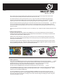
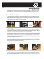
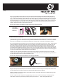
page 1
Hub Service Guide
(Rear Mtn. Hub )
Section 1: Bearing Play Adjustment
Industry Nine wheels are equipped with the highest quality ABEC5 bearings from the factory. Over time, all bearings will wear,
developing some lateral play. Occasionally, during the break-in process, as bearings and other parts of the assembly seat more firmly,
unsatisfactory lateral play may also develop.
1.1 Required Tools
Adjustment will require a 1.5mm allen wrench, and may be performed with the wheel installed or removed from the bicycle.
NOTE: Due to the preloading nature of 10 and 12 mm through-axle designs, it is recommended that these hubs be adjusted while
installed on the bike.
1.2 Adjustment
Find the 1.5mm allen head setscrew in the non-drive-side dustcap (fig. 1) . Loosen the setscrew 2 full turns to ensure the end of the
screw clears the surface of the axle. The dustcap should turn freely once the setscrew is loosened. If not, use the allen wrench to gently
apply enough leverage to turn the dustcap. If the dustcap seems stuck, attempt to loosen it first by applying counterclockwise force
(looking from the disc side).
Tighten the dustcap by hand until it stops against the disc-side bearing. Do not apply excessive torque, as this will cause premature
bearing failure. Once freeplay is removed and dustcap is finger-tight, gently tighten the setscrew. This is a 3mm thread on a pointed
setscrew, and as such requires very little torque (1.0 Nm / 8.8 in-lb). A good rule of thumb is 1/8 turn past the point at which the screw
contacts the axle.
If lateral play remains after performing this adjustment, please continue to bearing replacement, as the bearings have probably
exceeded their service life.
1.5 mm
set screw
Fig. 1
Section 2: Freehub Drive Mechanism Service
The recommended inspection and service interval for Industry Nine’s patented drive mechanism is annually. This is a recommendation
only, and may have to be adjusted for severe climates, wet environments, frequency of riding, etc. It is recommended to service the
drive mechanism during bearing replacement, as it must be disassembled to perform this maintenance.
2.1 Required Tools
Tools required for service; 1.5 mm allen wrench, two (2) 5mm allen wrenches, a soft-faced (plastic or brass) hammer, and a soft-metal
(such as brass or aluminum) drift punch or rod approximately 6" long x 1/2" diameter. A hard benchtop material such as formica or
metal will also prove convenient. Removal of the pawls and springs will require a .050" allen wrench, which is usually the smallest in an
English set. These .050" allen wrenches are also available from Industry Nine for the cost of postage. A scribe or very small jeweler’s
screwdriver will be required for retaining clip removal.
2.2 Disassembly
Remove the wheel from the bike and the cassette from the freehub body. It is not necessary to remove the disc rotor.
Remove the disc-side adjusting dustcap from the axle by first loosening the 1.5mm allen setscrew in the dustcap 2 full turns. Remove
the dustcap by unscrewing it counter-clockwise until it comes free of the axle. Place it to one side.
page 2
Next, remove the drive-side steel endcap by placing a 5mm allen in each end of the axle and unscrewing the drive-side end. Also
remove the axle spacer by sliding it off the drive end of the axle. Place these to one side.
The freehub mechanism is pressed into the hubshell. To remove it, support the hubshell to the outside of the large back flange of
the freehub. This can be done by padding a bench vise opened far enough to clear the freehub, or with two wood or plastic blocks
supporting the hub above a bench. Alternatively, the hub may be supported by the hand not wielding the hammer
(fig 2 & 3) .
Remove the freehub mechanism by gently tapping the non-drive (disc side) end of the axle with a soft-faced hammer
(fig 2 ). Take care
to ensure the mechanism remains straight in its bore as it comes out or pawl spring damage may occur. Again: GENTLY tap the nondrive end of the axle until the large bearing comes free of the hub. The axle will slide all the way through the hub and come out the drive
side with the freehub.
Firmly grasp the large end of the axle and slide it out of the fr eehub bearings. (Fig. 4) depicts the freehub assembly and axle clear of the
hub.
2.3 Pawl and Spring Removal
The pawls must be removed in order to replace the large 61808 bearing. It is also recommended that they be removed annually for
thorough cleaning and regreasing. If they appear to be well-greased and free of contamination, it is not necessary to remove them from
the mechanism for simple inspection or addition of grease.
Establish a clean, solid working area, as some parts are very small. One at a time, remove each spring retaining screw using a .050"
allen wrench. Then remove the spring and pawl, taking care not to lose any of the tiny screws. Place these parts far out of the reach of
swiping rags and mishandled tools.
To change from 3 degree to 6 degree engagement, simply remove three alternating pawls and springs, leaving one set of three pawls in
place in an equilateral triangle (fig 5) . Alternatively, to change from 6 degree to 3 degree engagement, replace the missing three pawls
and springs following the instructions in section 3.2 “Pawl and Spring Installation” .
Fig. 2
Fig. 3
Fig. 4
Fig. 5
2.4 Bearing Removal
At this point, the two 61903/29.5 bearings inside the cassette body and the 61804 bearing in the disc side of the hub may be r
emoved
using a press or soft-metal drift punch. A rod or socket with a diameter of 18mm will allow easy removal of both cassette body bearings
from the back. Ensure the cassette body is well-padded when supported in a press or bench vise to prevent damage.
NOTE: Removal of bearings using a drift punch will usually damage them, r endering them useless.
The spacer between the 61903/29.5 bearings should slide out easily by hand once the outer bearing is r
emoved.
If the large 61808 bearing exhibits play or roughness, it should also be replaced. In order to remove this bearing from the freehub body,
the six pawls and their respective springs must first be removed. Please refer to Section 2.32 “Pawl and Spring Removal” prior to
attempting to remove the 40x52mm 61808 bearing.
To remove the 61808 bearing, first remove its retaining clip by GENTLY and CAREFULLY prying one end free of its groove using the
point of a scribe, jeweler’s screwdriver, or knife. USE CARE to not stab yourself. Once one end of the clip is lifted free, gently work it out
of the groove all the way around to the other end, taking care not to twist or otherwise mangle the retaining clip. Once free of its groove,
remove the clip and place it to one side.
page 3
Remove the bearing by repeatedly firmly tapping the back of the freehub against a hard surface (non-marring), such as a wooden or
formica benchtop (fig 6) . Inertia will cause the bearing to slide free of the freehub body. DO NOT use a metal or concrete surface to
accomplish this as it will damage the aluminum freehub. Often, the bearing can be removed using one’s fingernails behind the outer
race. Take care not to peel your nails back attempting this.
Section 3: Hub Reassembly
Bearings are best installed in hubshell and cassette body using an arbor press. If a press is not available care must be taken using other
methods to ensure the bearings are pressed in their respective bores completely straight. When pressing bearings into bores find a
socket or other cylindrical object to apply pressure to only the outer race of the bearing, as pressing the inner races or dust seals will
damage the bearings. Likewise, when pressing bearings onto the outside of bearing journals, apply pressure only to the inner race. If
using a bench vise, soft metal or flat (non-toothed) jaws are recommended. Ensure all bearing mating surfaces are clean and free of grit
or dirt prior to installation. A very light coat of grease is always recommended.
Bearing
retainer clip
Fig. 6
Fig. 7
Fig. 8
3.1 Bearing Installation
To install the 61903/29.5 bearings in the cassette body, slip the first bearing in past the threads, until it begins to press. Then use the
7075 bearing spacer atop the bearing to press it in until the end of the spacer is flush with the end of the cassette body
(fig 7) . Place
the second bearing on the end of the spacer and press it in until it is also flush. Using the appropriately sized socket (or an old bearing),
continue to press the outer bearing until both bearings and spacer are firmly seated in the bearing bore.
The large 40mm x 52mm 61808 bearing is installed on the back of the fr eehub body by first starting the bearing past the retaining ring
groove. The bearing journal is slightly undersized for the first millimeter to aid in starting the bearing straight. The bearing can often be
completely installed with firm hand pressure. If a press is necessary, find a cylindrical piece of material (a short piece of 2” PVC pipe
works well) that fits on the inner race of the bearing and gently press it on the freehub until the retaining ring will fit in its groove (fig 8) .
Install the retaining clip, ensuring it is completely seated in its groove by firmly pushing it down into the groove starting at one end of the
clip and working completely around to the other end (fig 9) .
To install the 61804 bearing in the non-drive end of the hub, start the bearing into the end of its bore by hand. Find an appropriately
sized socket or use the old bearing to carefully press the bearing until it is firmly seated in its bore (fig 10) . Work carefully to ensure the
bearing remains completely straight during the entire process. Pad the drive end of the hubshell with a non-marring material such as
plastic or wood to ensure the freehub bearing bore is not deformed.
Once the bearings are installed, the pawls and springs may be reinstalled on the freehub body.
Fig. 9
Fig. 1 0
Fig. 1 1
3.2 Pawl and Spring Installation
If the pawls and freehub body have been degreased, apply a small dab of grease to each pawl pocket to assist in keeping the pawls in
place during spring installation (fig 11) . If available, it is also recommended to apply a tiny drop of medium-strength Loctite to each of
the similarly-sized pawl spring retaining screws.
page 4
One at a time, reinstall the springs. Place the spring in its recess on the freehub body. Note that the spring is shaped such that it can
only be properly installed in one orientation. Ensure that the radiused corner of the spring is oriented toward the large 61808 bearing
(fig 12) . Install the screw carefully, ensuring it does not cross-thread. As the screw is tightened, gently apply pressure on the pawl and
spring towards the back of the pawl pocket to ensure the pawl remains fully engaged in the pocket and the spring is not twisted away
from the large bearing (fig 13) . These screws are size 0-80 using a .050” (~1.2mm) allen wrench, and as such, require a tiny amount of
torque (<3 in-lb). Tighten no more than 1/10 of a turn past snug. Repeat the process until the desired number of pawls are in place; 3
pawls for 6 degrees or 6 pawls for 3 degrees before engagement.
Once the pawls and springs are installed, the freehub assembly may be reinstalled in the hub.
Insert radiused
edge of spring
into the radiused
pocket of
cassette body.
Fig. 1 3
Fig. 12
3.3 Drive Mechanism Installation
If old grease has been cleaned or the mechanism has been degreased, apply a liberal amount of light grease to the drive ring cavity and
pawl mechanism (fig 14) . Drive mechanisms are factory assembled with DuMonde Tech Freehub Grease. 1 oz. containers are available
directly from us or DuMonde Tech. If unavailable Slick Honey, Rock ‘n’ Roll Super Slick, or Dumonde Tech liquid grease will work.
To ease reassembly of the drive mechanism, there are six slots milled into the circumference of the drive ring (fig 15) . These accept the
pawls and simplify the reengagement of the pawls in the drive ring. Begin reassembly by visually lining up the pawls with these slots.
Once lined up, gently push the pawl mechanism into the bore by hand approximately 1 millimeter until it the pawls stop against the
drive ring. The large bearing bore is slightly oversized at the outer end to ease straight installation. Continue the process by rotating the
freehub backwards (freewheeling) to engage the pawls in the drive ring. Feel and listen carefully for smooth, consistent pawl ratcheting.
Once the pawls are engaged, push the freehub body into the hubshell by hand approximately another millimeter until the bearing begins
to press fit. Once again verify the smooth operation of the pawl mechanism.
Complete the process by pressing the assembly into the hub until it is fully seated. Use the utmost caution to ensure the assembly
remains absolutely parallel to its center axis or pawl spring damage will occur. When the freehub is fully seated, the largest diameter of
the freehub flange will be flush with the edge of the hubshell (fig 16) .
Once the drive mechanism has been reassembled, the rear axle may be reinstalled.
Drive ring slot
(1 of 6)
Fig. 1 4
Fig. 15
Fig. 16
3.4 Axle Installation
Begin by replacing the adjusting dustcap on the axle. Thread it on clockwise until the outer edge of the dustcap ish flush with the end of
the axle. Slide the axle into the hub from the disc end until the adjusting cap stops against the bearing.
Slide the axle spacer on the drive end of the axle and reinstall the stainless steel endcap. Tighten gently to 4 Nm/35 in-lb using a 5mm
allen wrench in each end of the axle.
Push the axle back to the disc side by hand or by gently tapping the drive end on a workbench. Hand tighten the adjusting dustcap
against the disc-side bearing. Adjust bearing freeplay by following the instructions in “Section 1: Bearing Play Adjustment.”