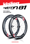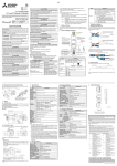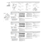
1
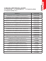
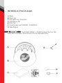
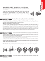
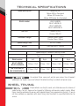
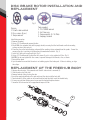
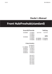
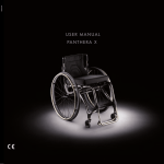
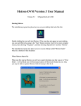
USER’S MANUAL AND
INSTRUCTIONS
User’s Manual and Instructions
Installation instructions
Warranty
Wheels package
Wheelset installation
Wheel Preload Hub Adjustment
Technical specifications
Spoke replacement and lacing
Replacement of the freehub body
Maintenance recommendations
Wheel replacement parts
04
04
07
08
09
11
12
13
14
15
4
INSTALLATION INSTRUCTIONS
Congratulations on your Vision product. Please read these instructions and follow them
for correct use. Failure to follow the warnings and instructions could result in damage
to product which is not covered under warranty, damage to bicycle or cause an accident
resulting in injury or death. Since specific tools and experience are necessary for proper
installation, it is recommended that the product be installed by a qualified bicycle
technician.
WARRANTY
Full Speed Ahead (FSA) warrants all FSA, Gravity, Vision, Metropolis and RPM products
to be free from defects in materials or workmanship for a period of two years after
original purchase unless otherwise stated in the full warranty policy. The warranty is nontransferable and valid to the original purchaser of the product only. Full warranty policy
is available at:
FULLSPEEDAHEAD.COM WARNING
Regularly check the wheels to be certain they are fastened securely to
the bicycle fork. If the Quick Release or through axle are not istalled correctly, the wheel may become
separated from the fork and result in an accident, personal injury or death.
WARNING
Tires mounted on clincher wheels should not be inflated above 125 psi.
(8.5 bar). Tires mounted on tubular wheels should be inflated per tire manufacturer recommendations.
VISION METRON 40DB
(VT-840/DB - VT-840/DB-CL - VT-840CH/DB
VT-840CH/DB-CL)
PRODUCT
ITEM CODE
METRON 40 DB CL Clincher VT840CH/DB-CL Front Wheel Red Decal
710-0013073030
METRON 40 DB CL Clincher VT840CH/DB-CL Front Wheel Grey Black Decal
710-0013073031
METRON 40 DB CL Clincher VT840CH/DB-CL Rear Wheel Shimano Red Decal
710-0013084030
METRON 40 DB CL Clincher VT840CH/DB-CL Rear Wheel Shimano Grey Black Decal
710-0013084031
METRON 40 DB CL Clincher VT840CH/DB-CL Wheelset Shimano Red Decal
710-0013091030
METRON 40 DB CL Clincher VT840CH/DB-CL Wheelset Shimano Grey Black Decal
710-0013091031
METRON 40 DB CL Tubular VT840/DB-CL Front Wheel Red Decal
710-0029053031
METRON 40 DB CL Tubular VT840/DB-CL Front Wheel Grey Black Decal
710-0029053030
METRON 40 DB CL Tubular VT840/DB-CL Rear Wheel Shimano Red Decal
710-0029064031
METRON 40 DB CL Tubular VT840/DB-CL Rear Wheel Shimano Grey Black Decal
710-0029064030
METRON 40 DB CL Tubular VT840/DB-CL Wheelset Shimano Red Decal
710-0029101031
METRON 40 DB CL Tubular VT840/DB-CL Wheelset Shimano Grey Black Decal
710-0029101030
METRON 40 DB Tubular VT840/DB Front Wheel Red Decal
710-0148
METRON 40 DB Tubular VT840/DB Front Wheel Grey Black Decal
710-0148BKG
METRON 40 DB Tubular VT840/DB RearWheel Red Decal
710-0149
METRON 40 DB Tubular VT840/DB Rear Grey Black Decal Wheel
710-0149BKG
METRON 40 DB Tubular VT840/DB Wheelset Shimano Red Decal
710-0152
METRON 40 DB Tubular VT840/DB Wheelset Shimano Grey Black Decal
710-0152BKG
METRON 40 DB Clincher VT840CH/DB Wheelset Shimano Red Decal
710-0154
METRON 40 DB Clincher VT840CH/DB Wheelset Shimano Grey Black Decal
710-0154BKG
5
6
WHEELS PACKAGE
A. Wheels
B. Wheels bag
C. Accessories bag + Instructions
D. Quick Release (QR)
E. Brake Pads
F. Valve Extensions (only VT-840/DB - VT-840/DB-CL)
G. Spoke Protector
Vision Spoke Protector is intended to prevent the chain from
falling down in the spokes. Please install it on the rear wheel before riding.
WARNING
E
F
WHEELSET INSTALLATION
1.For mounting tires, carefully follow the instructions provided by the tire
manufacturer.
2.Apply light grease onto the Freehub Body. Install the cassette per
manufacturer’s recommendations. The Shimano freehub body is
compatible with S11 cassette. A spacer (A) is required when mounting
S9 & S10 cassette.
WARNING
7
Do not use Vision carbon specific pads with non carbon (alloy) rims.
3. Insert the Quick Releases into the wheel. The lever of the Quick Releases should go on the nondrive side. Thread the Quick Release nut, but do not tight.
Note: Front Quick Release is shorter than rear.
4. Install the Front and Rear Wheel into the drop-outs of the fork and frame. With the QR lever in
the open position, tighten the QR until it is in contact with the frame or fork dropouts. Close the QR
lever. The QR lever should require substantial effort to close the last 25-30 degrees. If it closes with
only moderate hand pressure, the QR must be readjusted by opening the QR lever, then turning the
QR nut clockwise until the closing action of the QR lever requires the recommended force.
WARNING
• If you are unfamiliar with Quick Release assembly it is recommended to ask
for advice from your local bike shop. Riding with an improperly assembled Quick Release can cause the
wheel to shift while in use resulting in accident and injury.
• Regularly check the QR adjustment. If the Quick Release is not installed correctly, the wheel may become
separated from the fork and result in an accident, personal injury or death.
• Always close the skewer lever completely. Do not allow a frame or fork tube or any other member to
inhibit full lever travel when closing. Failure to close the lever completely will limit cam engagement and the
skewer’s ability to hold the wheel in place.
Note: The QR must be periodically lubricated at the pivot points so it can exert maximum sideways force.
NO
WARNING
manufacturer
• If you use through axle fixing device check instructions of through axle
TECHNICAL SPECIFICATIONS
Wheel Description
Metron 40 Disc
Metron 40 Disc Centerlock
Metron 40 Clincher Disc
Metron 40 Clincher disc Centerlock
Model number
WH-VT-840/DB
WH-VT-840/DB-CL
WH-VT-840CH/DB
WH-VT-840CH/DB-CL
Rim size
Tubular 633x24
Clincher 700x17C
Rim width / height
Tubular 24mm / 40mm
Clincher 25mm / 40mm
Spokes Gauge / End
AE-14G / J-Bend
Nipples
15mm ABS Brass - external
8
Spokes Lengths / Number x Crossing Pattern
Front
Right
Model number
Left
Right
Left
Right
WH-VT-840/DB
WH-VT-840CH/DB
269mm / 12x2
274mm / 12x2
269mm / 14x2
278mm / 14x3
WH-VT-840/DB-CL
WH-VT-840CH/DB-CL
274mm / 12x2
274mm / 12x2
281mm / 14x3
278mm / 14x3
WARNING
Use original Vision spare parts only for your service. Use of incorrect
spoke types and lengths may cause failure of the wheel resulting in accident and person injury.
WHEEL TRUING
CAUTION
Bicycle wheels are straight, round, and stable because of a balance of
spoke tension. The rim’s shape can be changed by tightening and loosening spoke’s nipples. Wheel
truing should be performed by persons with adequate wheel truing experience or training. If you do
not have confidence or experience with wheel truing, take the wheels to a qualified technician for
service.
SPOKE REPLACEMENT AND LACING
CAUTION
CAUTION Before replacing a spoke, please check the above technical
specifications for the correct spoke length and type.
Always use original Vision spare parts before proceeding with the replacement.
1. Depending on the side where the broken spoke is, remove disk brake rotor or cassette
2. Remove the spoke and nipple to be replaced and install the new one with proper positioning to
adjacent spokes
3. Secure the spoke to the rim by tightening the nipple
4. Use a spoke tension measuring device to follow the recommended tension as in the chart below
5. After replacing the spoke, tensioned and centered the wheels, check that the flat spoke (aero) is
oriented in the aerodynamic position and is not twisted
6. Mount disk brake rotor or cassette
WARNING
Maximum spoke tension must not exceed the tension specification (see
chart below). Using tension above max recommended tension will void warranty and cause wheel
failure resulting in serious accidents and injury. If tension above maximum is necessary to true the
wheel, the rim may be damaged and should be replaced.
Always avoid the rotation of the spoke (spoke wind-up) when the nipple is tightened or loosened by
using an anti-rotation spoke tool.
RECOMMENDED SPOKE TENSION
Front Wheel
Rear Wheel
Left Side
Right Side
Left Side
Right Side
90 - 110 kg
60 - 80 kg
60 - 80 kg
100 - 120 kg
9
DISC BRAKE ROTOR INSTALLATION AND
REPLACEMENT
10
Fig.1
Fig.2
Figures:
1. 6-bolts rotor and hub
2. Disc screws (6 pcs)
3. Torque wrench
Fig.3
Tools needed:
1. T25 TORX® wrench
2. Lint-free rags
3. Torque wrench (5.7-6.3Nm)
4. Isopropyl alcohol
Installation procedure
1. Remove the wheel
2. Using a T25 Torx® wrench remove the disc
3. Clean NEW disc and wheel hub with Isopropyl alcohol, ensuring that the hub threads and hub mounting
surface are free of dirt and grit
4. Place the disc on the hub mounting surface with the markings facing outward from the spokes. Ensure the
arrow on the disc is pointing in the direction of forward wheel rotation. (Fig 1)
5. Install all 6 bolts and snug hand tight. (Fig 2)
6. Using a T25 Torx® wrench, tighten the disc screws (6 pcs) in a star pattern to 6 Nm. (Fig 3)
CAUTION: Do not over tighten the disc screws, to prevent damage to the threads, disc, or screws.
7. Reinstall the wheel
8. Spin the wheel to ensure that the rotor is not rubbing against the brake pads. If there is rubbing, re-align
the caliper.
REPLACEMENT OF THE FREEHUB BODY
1. Unscrew the axle using 17mm wrench until the left side end nut is removed (4)
2. Slide the axle out of hub shell
3. Remove freehub sliding it along the axle
4. Insert the new freehub body on the axle and insert the axle inside the hub shell
5. Turn freehub till all the pawls are in line with ratchet and then fully insert the freehub body
6. If necessary, add low-friction grease to preserve the freehub body mechanism
7. Screw the left side end nut at an approximate torque of 8 Nm
4
4
WHEEL MAINTENANCE
RECOMMENDATIONS
It is the user’s responsibility to examine the product on a regular basis to determine the need for service or
replacement. Cyclists should inspect their bicycle and parts on a regular basis in order to detect damage
that may have occurred from normal use or for missing parts. Check all parts for damage and wear before
every use. Should any problems or concerns arise, discontinue riding the bicycle and have it inspected by
a qualified bicycle technician.
11
Using wheels that have not been installed or centered correctly, present
broken, damaged, or has missing parts may fail or cause rider to lose control of bicycle leading to accident,
resulting in personal injury or death.
WARNING
HUB MAINTENANCE
Vision hubs are equipped with high grade, precision, sealed cartridge bearings. Due to varying factors it
is important to have the hub bearings inspected and maintained periodically. The recommended service
intervals are:
• Inspection after each riding season, one calendar year, or 8,000 to 10,000 Km, whichever comes first.
• After use in rain, storm, muddy, and wet conditions
• Anytime rotational smoothness, signs of corrosion, damage to rubber seals and bearing covers is
apparent.
Tech Tips:
• Avoid getting solvents, aerosol lubricants (as for chain), and strong cleaning solutions on the hubs. The
solvent can wick passed the seals and break down the bearing grease.
• When washing the bike, use only mild soap and a gentle stream of water for rinsing. Always avoid
pressure washing. Such systems can direct super heated water with special wetting agents at 10X
atmospheric pressure, forcing water passed the bearing seal and removing vital bearing grease.
CAUTION
Since specific tools and experience are necessary for hub maintenance, it is
recommended that the service should be done by a Vision Authorized Service Center.
Please contact the Authorized Vision Distributors and Warranty Service Centers closest to your country of
residence. A list of Authorized is posted at VISIONTECHUSA.COM.
RIM MAINTENANCE
-When braking, especially during descents, use both front and rear brakes. Front and Rear brakes have
different benefits and limitations, so use them according to instructions from an experienced rider. It is
important that both rims are employed during descents to properly dissipate heat.
-If, during frequent inspections, noticeable impact damage or any other deformation of the rim is
apparent, discontinue use and immediately seek advice from an experienced mechanic. If an experienced
mechanic is unavailable, contact Vision directly at
VISIONTECHUSA.COM.
WARNING
In the event of a bicycle accident, discontinue riding the bicycle until it has
been thoroughly examined by a qualified bicycle mechanic, and any damaged parts replaced.
WHEEL REPLACEMENT PARTS:
Replacement parts are available for purchase through all bicycle service and retail locations. If the
bicycle shop does not stock the necessary parts, it can be ordered by the retail location from a VISION
distributor or VISION directly. A list of distributors is available at VISIONTECHUSA.COM.
FULL SPEED AHEAD EUROPE
VIA DEL LAVORO, 56
20874 BUSNAGO, MILAN, ITALY
PH. +39 039 688 52 65
FAX +39 039 682 33 36
FULL SPEED AHEAD USA
12212 CYRUS WAY
MUKILTEO, WA 98275-5702
PH. +1 425 488 86 53
FAX +1 425 489 10 82
TH INDUSTRIES
NO.6, WUGONG 8TH RD., WUFENG DIST.,
TAICHUNG CITY 41353 - TAIWAN (R.O.C.)
PH. +886 4 2331 9134
FAX +886 4 2331 1943
If you have questions, please visit our web site contact page at:
VISIONTECHUSA.COM.
Notes: Specifications of product may be changed or improved for performance. Please refer to
website periodically for technical updates and revised instructions.