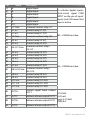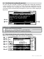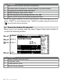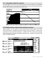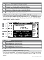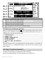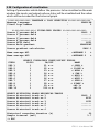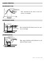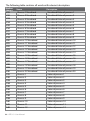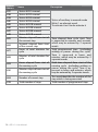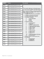
1
ATR 313
Controller
User manual
Contents list
1 Process controller ATR 313........................................................................................... 4
1.1 Keys and LCD display ........................................................................................ 4
1.2 Sizes and installation ........................................................................................ 5
1.3 Electrical wirings ................................................................................................ 6
1.4 Serial communication port ............................................................................. 6
2 Data acquisition module PL300 ................................................................................ 7
2.1 Frontal panel and Terminals block ................................................................ 7
2.2 Sizes and installation ........................................................................................ 8
2.3 Electrical wirings ................................................................................................ 9
2.4 Select type of linear output ...........................................................................11
2.5 Selection of communication address .........................................................11
2.6 Hardware data PL300 .....................................................................................12
2.6.1 Inputs for processes PROC. 1÷20..................................................12
2.6.2 Outputs for control-loops ...............................................................13
2.7 Modify parameters on ATR313 .....................................................................14
3 “Alfa” software version for firing cycles with multiple steps on gas ................15
3.1 General features ...............................................................................................15
3.2 Standard configuration for inputs/outputs ..............................................16
3.3 Main stop window (for operator)................................................................17
3.4 Start historical recording (for operator) .....................................................18
3.5 Main window during cycle execution (for operator) ...............................18
3.6 Menu cycle window (for operator) ..............................................................19
3.7 Cycle programming - Modify/visualize cycle data - (for operator) ......20
3.8 Process status (for operator) .........................................................................21
3.9 Cycle graph window (for operator) .............................................................22
3.10 Modify auxiliary outputs AUX5..AUX8 (for operator) ..............................22
3.11 Historical graph of cycle (for operator) ......................................................23
3.12 Manual advancement of cycle (for operator) ...........................................24
3.13 Manual control window (for operator) ......................................................24
3.14 Manual control SPV1 and SPV2 (for operator).........................................25
3.15 Manual control auxiliary outputs AUX1..AUX4 (for operator) ..............26
3.16 Manual control AUX1B..AUX4B (for operator) ..........................................26
3.17 Main menu window (for operator) ..............................................................27
3.18 Events list window (for operator) .................................................................27
3.19 Timers window (for operator) .......................................................................29
3.20 Display setting window (for operator) .......................................................30
ATR 313 - User Manual - 3
3.21
3.22
3.23
3.24
3.25
3.26
3.27
3.28
3.29
3.30
3.31
3.32
3.33
3.34
3.35
3.36
3.37
3.38
3.39
3.40
3.41
3.42
3.43
3.44
3.45
Clock setting wiondow (for operator) .........................................................30
Gas/air servo calibration (for operator) .....................................................31
Air/gas servo calibration menu n° 1 (for operator)..................................31
Gas/air servo calibration no. 2 (for operator)..........................................33
Configuration menu .......................................................................................34
General configuration ....................................................................................34
Configuration SPV1 and SPV2 ......................................................................34
Configuration of visualization......................................................................38
Special functions..............................................................................................41
Configuration ATR313 / PL300......................................................................44
Configuration of processes ............................................................................46
3.31.1 Source of setpoint value..................................................................48
Configuration of digital inputs PL300.........................................................48
Configuration of outputs PL300 ...................................................................50
Alarms configuration ......................................................................................52
Load / Save configuration .............................................................................56
Load standard configuration........................................................................56
Load configuration from Memory Card .....................................................56
Save configuration on Memory-card..........................................................56
Loading in progress .........................................................................................57
Failure and anomaly messages windows..................................................57
3.40.1 Configuration parameters/data lost ...........................................57
3.40.2 Communication errors ....................................................................58
3.40.3 Sensors failure ...................................................................................59
3.40.4 Hardware failure ...............................................................................59
3.40.5 Failure of Air/gas servo ...................................................................60
3.40.6 Failure or error in memory-card management .........................60
Wiring test PL300 .............................................................................................61
Enable/Desable functions .............................................................................62
Special functions..............................................................................................62
3.43.1 Working cycle recovery interrupted for power failure .............62
3.43.2 Waiting ...............................................................................................63
3.43.3 Rate of power consumption...........................................................63
3.43.4 Gas/air modulation by module PL250 .......................................64
Kit ATR313-UP ...................................................................................................64
Communication protocol Modbus-RTU .....................................................66
4 - ATR 313 - User Manual
1
Process controller ATR 313
Graphic Terminal, LCD 251x146mm, Multi-loop. Combined with a variable
number of data acquisition modules Pixsys PL300 , it offers a complete and
flexible control system for the management of thermal processes on industrial
kilns, dryers, environmental chambers.
On the frontal panel there are 32 keys, including alphanumeric keyboard,
function keys to select menus and to activate special functions.
The LCD graphic display (240x128 pixel) allows to visualize both graphs and
alphanumeric data.
Two leds inform the operator about the status of Terminal.
1.1 Keys and LCD display
2
6
1
ES C
5
TEXT
+
TEXT
-
4
7
3
Ref.
1
2
3
4
5
6
7
Description
LCD Display 240x128, backlightened, “reverse” function.
Screen-saver management with programmable switching of lamp are
configurable via software.
Function keys to select menus on display.
Select main functions of the terminal.
Key to enter configuration menu. It is used also as Esc key.
Led Start / stop. Meaning of leds varies according to software version
loaded on terminal.
Alphanumeric keyboard to enter numbers or alphanumeric strings.
Arrow keys to place cursor and enter blank space during the writing.
ATR 313 - User Manual - 5
1.2 Sizes and installation
18
48 mm
174 mm
MEMOR Y A TR313 / DKC58
C.S. 0300.10.159
CN1
Ciclo
CICLO 1
PV
TEMPERATURA
146 mm
PRESSIONE
AUX
REC
Hand
16/10
STOP
SPV1
SPV2
GRAD.
TEMPO
STEP
12.30
APRI
29 °C
0.150 mBar
_ _ _ _°C
_ _ _ _ mBar
_ _ _ _ /min
_ _ : _ _ /12.30 h:m
_ _ /05
CHIU.
BRUC.
VENT.
CAM/A
CAM/C
AUX 1
AUX 2
ALL. 1
ALL. 2
TEXT
ESC
+
TEXT
-
251 mm
42mm 42mm
inserimento insert
Memory Card Memory Card
COM2
RS422\485
0V
7
0V
2
CL/OUT-
18
RX -
12
TX232
4
CL/OUT+
RX +
11
RX232
6
CL/IN-
16
TX -/RX -
8
CL/IN+
15
TX+/RX+
RS232C
0V
5
0V
RS485+
3
RX
2
TX
8
9
A LIMEN TA ZION E
SUPPL Y
6 - ATR 313 - User Manual
Adattatore
RS485
RS232 PROGRAM.
1620.00.048
Cavo RS485
RS485-
1
Spessore suggerito
2÷9 mm
Suggested thickness
Dima di foratura
178 x 125 mm
Frontal panel cut-out
COM1
RS485
5
4
DB9 MA
122 mm
DB25 FE
C.L. PASSIVE
17
7
DB9 FE
RS232C
ALARM + V
2
0V
3
+V
12 ÷ 24
Va c / d c
1 0 VA
Adapter
DB9MA > PLUG8
Cod. 1620.00.028
Cable
PLUG8 > PLUG8
Cod. 1620.00.048
1.3 Electrical wirings
Although this controller has been conceived to resist the worst
noises in an industrial environment, please notice the following
safety guidelines:
• Separate control wires from power wires
• Avoid mounting close to remote control switching systems,
electromagnetic relays, powerful engines
• Avoid proximity of power systems, especially those with
phase control.
Terminals block
1
ALARM +V
2
0V
3
+V
Alarm signal. In case the internal buzzer is activated
(any general alarm), an external siren may be supplied by this pin (and pin 0V) with the same tension
of power supply (max. 5 A).
Power supply 12÷24V AC\DC 10VA. To improve
noises immunity, it is highly recommended to use
a transformer with dedicated secondary.
Terminal block features
Contacts
Material
Cables
Extractable
PA V2
AWG 28-16
Insulation
Current
600 V
8A
1.4 Serial communication port
Connection DB9 FE COM1
RS485
0V (pin 5)
RS+ (pin 4)
RS- (pin 9)
Connection to COM1 of PL300 by means of cable DB9M – Plug8M, which is supplied with the terminal.
Connection DB25 FE COM2
Connection to PC for software upgrade, reading and writing of
data, configuration parameters and cycles stored on terminal via
serial cable.
RS485
Connection to PC for reading and writing of data, configuration
0V (pin 14) parameters and cycles stored on Terminal by MODBUS protocol.
RS+ (pin 15) Connection of a Pixsys PL250 for gas/air modulating valves (opRS- (pin 16) tional).
RS232
ATR 313 - User Manual - 7
Connection DB25 FE COM2
RS422
0V (pin 14)
TX+ (pin 15) Connection to PC for reading and writing of data, configuration
TX- (pin 16) parameters and cycles stored on Terminal by MODBUS protocol.
RX+ (pin 17)
RX- (pin 18)
2
Data acquisition module PL300
Module PL300 joined to the Terminal ATR313 is data acquisition/activation
module to control thermal processes or other physical values. This dedicated
configuration does not involve the typical operating as PLC and it is focused on
the management of analog inputs and control outputs for Open/Close function
and alarm configurations which are usually required for control loops on industrial applications.
Hardware features include 4 analog inputs for TC/RTD/ linear signals, 6 digital
inputs, 12 relay outputs (two change-over relays 8A), programmable alalogue
outputs.
The module communicates with Terminal ATR313 via serial comunication RS485
and Pixsys protocol.
2.1 Frontal panel and Terminals block
37 38 39 40 41 42 43 44 45
28 29 30 31 32 33 34 35 36
1
10 11 12 13 14 15 16 17 18
19 20 21 22 23 24 25 26 27
46 47 48 49
RT 1
2
3
1
2
3
4
5
5
6
7
8
9
13
1
9
6
8 - ATR 313 - User Manual
DB9 FE
COM1
25
10
22
5
1
18
14
DB25 FE
COM2
Ref.
Description
1
Plug connector – Connection to terminal ATR313
Status leds:
Green led RUN >ON when PL300 is working.
Yellow led COM > ON if comunication in progress.
Red leds OUT 1..12 > ON if output is active.
Green leds IN 1..10 > ON if digital input is active.
Slave number of module PL300.
2
3
2.2 Sizes and installation
37 38 39 40 41 42 43 44 45
28 29 30 31 32 33 34 35 36
10 11 12 13 14 15 16 17 18
19 20 21 22 23 24 25 26 27
46 47 48 49
90
1
2
3
4
5
6
7
8
9
45
RT 1
43
53
5
Attacco a guida DIN EN50022
Din rail mounting guide EN5002 2
160 mm
ATR 313 - User Manual - 9
2.3 Electrical wirings
N°
Name
1
+
2
25
C
26
A
27
B
22
23
AN1+
AN1-
24
AN1C
19
20
AN2+
AN2-
21
AN2C
15
16
AN3+
AN3-
17
AN3C
12
13
AN4+
AN4-
14
AN4C
3
6
9
COM
INPUT
18
10 - ATR 313 - User Manual
Description
Supply 12÷24V AC\DC 10VA. To improve noises immunity,
the employ of the secondary of a dedicated transformer is
highly recommended.
Reference signal of serial Use these pins to expand
serial connection to ATR313
comunication port
on plants requiring more
modules PL300. In case of
RS485comunication via RS485,
connect all pins C of various
PL300 as well as pins A and
RS485+
B.
Positive signal for analog input AN1 (+Tc).
Reference signal analog input AN1 (-Tc).
Compensation PT100. For 3-wire PT100 connect compensation wire to this pin.
Positive signal for analog input AN2 (+Tc).
Reference signal for analog input AN2 (-Tc).
Compensation PT100. For 3-wire PT100 connect compensation wire to this terminal.
Positive signal for analog input AN3 (+Tc).
Reference signal for analog input AN3 (-Tc).
Compensation PT100. For 3-wire PT100 connect compensation wire to this pin.
Positive signal for analog input AN4 (+Tc).
Reference signal for analog input AN4 (-Tc).
Compensation PT100. For 3-wire PT100 connect compensation wire to this terminal.
Common positive signal for digital inputs. Connect this
signal to one of the digital inputs (I5÷I10) or to terminal “+” of
analog inputs (AN1÷AN4 if configured via software as digital
input), to activate the input (the relevant led switches on).
N°
11
10
8
7
5
4
28
29
30
31
32
33
Name
Description
47
Digital input.
Digital input.
Digital input.
Digital input.
Digital input.
Digital input.
Common contact relay U1.
Contact relay U1 N.C.
Contact relay U1 N.O.
Common contact relay U2.
Contact relay U2 N.C.
Contact relay U2 N.O.
Common contact relays
U3÷U7 Com
U3÷U7.
U3 n.a.
Contact relay U3 N.O.
U4 n.a.
Contact relay U4 N.O.
U5 n.a.
Contact relay U5 N.O.
U6 n.a.
Contact relay U6 N.O.
U7 n.a.
Contact relay U7 N.O.
Common contact relays
U8÷U12Com
U8÷U12.
U8 n.a.
Contact relay U8 N.O.
U9 n.a.
Contact relay U9 N.O.
U10 n.a.
Contact relay U10 N.O.
U11 n.a.
Contact relay U11 N.O.
U12 n.a.
Contact relay U12 N.O.
Positive signal linear output
OUT1+
OUT1.
OUT1Reference linear output OUT1.
48
OUT2+
49
OUT2-
34
35
36
37
38
39
40
41
42
43
44
45
46
I5
I6
I7
I8
I9
I10
U1 Com
U1 n.c.
U1 n.a.
U2 Com
U2 n.c.
U2 n.a.
To activate digital inputs,
short-circuit signal COM
INPUT on the pin of input.
Inputs Leds ON mean that
input is active.
8A ÷ 230Volt resistive
5A ÷ 230Volt resistive
0..10 Volt
4..20 mA
Logic 0-15 Volt
Reference linear output OUT1.
PWM 3 A
Reference linear output OUT2.
ATR 313 - User Manual - 11
Connect COM1
RS485
Connection to ATR313 by means of cable DB09 – Plug-8M supplied with the terminal.
2.4 Select type of linear output
PL300 is provided with 2 linear outputs (OUT1, OUT2) which must be configured via software and manually by selection of 2 dip-switches on board:
• Disconnect power supply PL300.
• Use a screwdriver to remove the upper cover of PL300
• Set dip SW1 (for OUT1) and SW2 (for OUT2) as shown here below to configure the output1.
ON
ON
ON
1 2 3 4 5 6
1 2 3 4 5 6
1 2 3 4 5 6
Logica 15V
4-20 mA
0-10 Volt
• Replace the upper cover and restart PL300.
2.5 Selection of communication address
PL300 is provided with 2 dip-switches to set the address of module for the
communication with ATR313. Up to four combinations are possible, therefore
if it is necessary to connect more than 4 modules on the same line, the parameter of address offset must be changed. The address of each module is exactly
defined as follows:
ADDRESS OF MODULE = OFFSET OF ADDRESS + COMBINATION OF DIP
The offset of address, which a value stored on memory of PL300 (default value
is “0”), may be modified writing on Modbus word 5.
To set the address , please proceed as follows:
• Disconnect power supply of PL300.
• Remove upper panel of PL300 with a screwdriver
• Set dip-switches SW1-1 and SW2-1 as shown below to get the value which
must be added to offset value in order to obtain the address value.
1
Dip SW1-1 and SW2-1 are not used for selection of linear output, but for selection of
address (see following paragraph).
12 - ATR 313 - User Manual
SW2
ON
SW2
SW2
ON
ON
SW2
ON
1 2 3 4 5 6
1 2 3 4 5 6
1 2 3 4 5 6
1 2 3 4 5 6
ON
ON
ON
ON
1 2 3 4 5 6
SW1
DIP=0
1 2 3 4 5 6
SW1
DIP=1
1 2 3 4 5 6
SW1
DIP=2
1 2 3 4 5 6
SW1
DIP=3
Replace the upper panel and restart PL300.
Terminal ATR313 may communicate with max. 5 modules PL300 which must
have the following addresses: 1, 2, 3, 4, 5. Many applications require one single
PL300: in this case there’s no need to make selections on the module because the
default address is 1 (OFFSET of ADDRESS=0, DIP COMBINATION=1).
2.6 Hardware data PL300
ATR313 and module PL300 allows the management of up to 20 different
control loops. Each control loop includes one input and one output, whose
positions are fixed hardware data of PL300. Therefore during the configuration
of the system please avoid to overlap other programmable outputs to the
outputs alredy fixed for control loops.
2.6.1 Inputs for processes PROC. 1÷20
Process
PL300 SLAVE#
Imput
1
2
3
4
5
6
7
8
9
10
11
1
1
1
1
2
2
2
2
3
3
3
AN1
AN2
AN3
AN4
AN1
AN2
AN3
AN4
AN1
AN2
AN3
ATR 313 - User Manual - 13
Process
PL300 SLAVE#
Imput
12
13
14
15
16
17
18
19
20
3
4
4
4
4
5
5
5
5
AN4
AN1
AN2
AN3
AN4
AN1
AN2
AN3
AN4
2.6.2 Outputs for control-loops
The following table summarizes the outputs which are used by control loops
referring to parameter “Type of output” (menu “PROCESS CONFIGURATION”).
Outputs which are not used for control-loops can be configured for other
functions with the menu “CONFIGURATION OUTPUTS PL300”.
Output PL300
Proc. SLAVE#
No out
On / Off
Time
Proport
USED OUTPUT
OUT1
LOGIC
Servo AC
4..20mA
0..10V
OUT2
LOGIC
4..20mA
0..10V
SSR
PROP T.
SSR
ON/OFF
1
1
-
U1
U1,U2
OUT1
OUT2
SSR1
2
3
1
1
-
U3
U5
U3,U4
U5,U6
OUT1
OUT1
OUT2
OUT2
SSR2
SSR3
4
1
-
U7
U7,U8
OUT1
OUT2
SSR4
5
6
7
8
9
10
11
12
13
14
2
2
2
2
3
3
3
3
4
4
-
U1
U3
U5
U7
U1
U3
U5
U7
U1
U3
U1,U2
U3,U4
U5,U6
U7,U8
U1,U2
U3,U4
U5,U6
U7,U8
U1,U2
U3,U4
OUT1
OUT1
OUT1
OUT1
OUT1
OUT1
OUT1
OUT1
OUT1
OUT1
OUT2
OUT2
OUT2
OUT2
OUT2
OUT2
OUT2
OUT2
OUT2
OUT2
SSR1
SSR2
SSR3
SSR4
SSR1
SSR2
SSR3
SSR4
SSR1
SSR2
14 - ATR 313 - User Manual
Output PL300
Proc. SLAVE#
15
16
17
18
19
20
4
4
5
5
5
5
No out
On / Off
Time
Proport
-
U5
U7
U1
U3
U5
U7
USED OUTPUT
OUT1
LOGIC
Servo AC
4..20mA
0..10V
U5,U6
U7,U8
U1,U2
U3,U4
U5,U6
U7,U8
OUT1
OUT1
OUT1
OUT1
OUT1
OUT1
OUT2
LOGIC
4..20mA
0..10V
SSR
PROP T.
SSR
ON/OFF
OUT2
OUT2
OUT2
OUT2
OUT2
OUT2
SSR3
SSR4
SSR1
SSR2
SSR3
SSR4
2.7 Modify parameters on ATR313
Independently from loaded software version (Alfa, Beta, Gamma), to modify
parameters it is necessary to refer to the following table.
Type
Example
Numeric
1200
Mnemonic
On
Example of parameters change
1. Use the arrow keys to place the cursor on the
data you want to modify.
2. Enter the choosen numeric value by means
of the alphanumeric keyboard. (Press DEL to
cancel one digit at a time)
3. Press OK to confirm the data. The cursor will
automatically move to the next changeable data
in the same page.
1. Use the arrow keys to place the cursor on data to
modify.
2. Press “SHIFT” to scroll all the settings available
for this parameter (“DEL” allows to search backwards).
3. Press OK to confirm the data. The cursor will
automatically move to the next changeable data
in the same page.
ATR 313 - User Manual - 15
Type
Example
Text
1. Use the arrow keys to place the cursor on data to
modify.
2. Cursor does not blink because the function
Modify is not yet enabled.
3. Press “OK” to enable function Modify ( cursor
Temperature
starts blinking).
4. Use the alphanumeric keyboard, the arrow keys
and “DEL” to enter the text.
5. Press OK to confirm the data. The cursor will
automatically move to the next changeable data
in the same page.
3
Example of parameters change
“Alfa” software version for firing cycles with multiple steps on gas
and electric kilns.
3.1 General features
This software is specially conceived for the management of gas and electrical
kilns, requiring the programming of cycles with a certain number of steps and
programmable setpoints. Main features include:
• 2 independent setpoints.
• Up to 20 independent control loops with PID algorithm.
• 20 cycles with 30 steps each , repetition of cycle
• Manual control of setpoints and outputs AUX1..AUX4
• Function “Waiting”
• Function “Recovery”
• Inputs and outputs free configurable.
• Programming of up to 30 alarms.
• Visualize the graph of cycle with advancement indicator.
• Record and visualize historical archiv of 6 traces for max. 75 hours.
• Rate of power consumption
• Serial communication via Modbus protocol; connection to PC and software
data logger “Datalogger_ATR313”.
16 - ATR 313 - User Manual
3.2 Standard configuration for inputs/outputs
Terminal ATR313 is supplied with a standard configuration which is described in
the following pages. This basic configuration allows the operating with a single
module PL300 (Slave #1) to control a gas kiln with a thermocouple type K.
These standard settings require the following electrical wirings.
Function and description
IN / OUT
Pins
TEMPERATURE termocouple K
OPEN ( servovalve control)
CLOSE (servovalve control)
BURNERS
FANS
AUX1
AUX2
STEPSTART
ALL.1
ALL.2
STEP+ & STEP=
STOP
GAS PREASSURE SWITCH
(stop cycle)
START (start cycle)
STOP (stop cycle)
AN1
U1 n.o.
U2 n.o.
U3 n.o.
U4 n.o.
U5 n.o.
U6 n.o.
U7 n.o.
U8 n.o.
U9 n.o.
U10 n.o.
U11 n.o.
U12 n.o.
22(+), 23(-)
28, 30
31, 33
34, 35
34, 36
34, 37
34, 38
34, 39
40, 41
40, 42
40, 43
40, 44
40, 45
I5 n.o.
9, 11
I6 n.o.
I7 n.o.
9, 10
6, 8
Below a description of all functions currently supported by “Alfa” software.
ATR 313 - User Manual - 17
3.3 Main stop window (for operator)
When cycle is not running the main window is visualized as follows:
1
7
8
Cycle CYCLE 1
PV
9
10
11
Ref.
2
STOP
3
23/11
5
10:46
OPEN
CLOSE
TEMPERATURE
BURN
FAN
°C
AUX1
AUX2
SPV1
---- °C
STEPOUT1
---- %
GRAD.
---- / ---- /min START
AL.1
TIME
--:-- / 00:00 h:m
AL.2
STEP
-- / 00
6
23
4
Description
1
2
Name of selected cycle
Status of cycle
Name/s and value/s visualized process/es (up to max. 4 processes
3
which can be selected from menu DISPLAY CONFIGURATION (parameters “Source 1÷4 process field”).
Cycle values (setpoint SPV1, setpoint SPV2, selected output value, real
4
and programmed gradient, elapsed time and total cycle time, number
of step in progress and total number of steps for the selected cycle).
5
Date and time
6
Brief overview about state of outputs and digital inputs
7
Cycle functions (menu for cycle configuration)
8
Visualize data about all processes
9
Graph of selected cycle
10 Modify auxiliary output AUX5..AUX8
11 Historical graph
Within this page in addition to menu selection keys, the following keys are also
active: “START” to start selected cycle, “HAND” to enable manual control and
to enter main menu window.
18 - ATR 313 - User Manual
3.4 Start historical recording (for operator)
At cycle start the controller visualizes a dialogue box asking the operator if
a new recording must be started or if data of previous registration must be
stored. Starting a new recording, the stored data will be deleted. Historical
recording shall be automatically interrupted at cycle stop or after elapsing of
fixed time.
Cycle CYCLE 1
23/11
STOP
10:46
OPEN
CHIU.
PV
TEMPERATURA
HISTORIC
GRAPH RECORDING
BRUC.
Stored data will be deleted by VENT.
starting a new recording!
°C
AUX1
Start a new registration?
AUX2
SPV1
---- °C
YES
STEPUSCITA1
---- %
START
NO GRAD.
STOP to
CANCEL
---- / ---/min
ALL.1
TIME
--:-- / 00:00 h:m
AL.2
STEP
-- / 00
23
1
2
Ref.
1
2
3
3
Description
Start a new historical recording.
Keep previous recording, do not start a new one.
Cancel operation, keep STOP condition of terminal.
3.5 Main window during cycle execution (for operator)
When cycle is in progress, main status window will be like this:
1
2
3
4
5
6
Cycle CYCLE 1
RAISING STEP
PV
23/11
TEMPERATURE
1323 °C
SPV1
OUT1
GRAD.
TIME
STEP
3.1 /
01:35 /
01 /
1324 °C
97.60 %
3.2 /min
02:00 h:m
03
10:46
OPEN
CLOSE
BURN
FAN
AUX1
AUX2
STEPSTART
AL.1
AL.2
ATR 313 - User Manual - 19
Ref.
Description
1
Menu to enter current cycle data visualization.
2
Visualize values of processes, control setpoint, % control output.
3
Cycle graph and advancement indicator
4
Modify auxiliary output AUX5..AUX8
5
Historical graph and recording indicator “>>> REC”.
6
Menu to enter cycle manual advancement function.
Within this page in addition to menu selection keys, the following keys are also
active: “START” to start selected cycle, “HAND” to enable manual control and
to enter main menu window.
3.6 Menu cycle window (for operator)
When cycle is not running, enter the menu “>Cycle” from main window to
visualize the following window:
1
Modif CYCLE 1
2
Cyc.+
3
Cyc.-
4
Esc
Ref.
1
2
3
4
STOP
10:46
OPEN
CLOSE
TEMPERATURE
BURN
FAN
°C
AUX1
AUX2
SPV1
---- °C
STEPOUT1
---- %
GRAD.
---- / ---- /min START
AL.1
TIME
--:-- / 00:00 h:m
AL.2
STEP
-- / 00
Description
Menu “Modify selected cycle”.
Load next cycle.
Load previous cycle.
Back to main window.
20 - ATR 313 - User Manual
23/11
23
3.7 Cycle programming - Modify/visualize cycle data - (for operator)
This window can be entered both with cycle in stop and in start, but the data
modification is allowed only in stop condition. During the cycle this window
only visualizes cycle data. The programming of selected cycle starts by entering the name of cycle, how many times the cycle will be executed , the steps
(time - SPV values) and the status of 4 auxiliary outputs AUX1÷AUX4.
Cycle modification/ visualization window:
************** PROGRAMMING CYCLE 1
Cycle name: < CYCLE 1 >
Execute cycle for 1 times
At cycle stop go to CYCLE
hh:mm SPV1
0
--:-1
01:00 1000
0
2
00:00
......
0
27 00:00
0
28 00:00
00:00 ------> ESC
St
**************
--
SPV2
0.00
1.00
0.00
A1
OFF
OFF
OFF
A2
OFF
OFF
OFF
A3
OFF
OFF
OFF
A4
OFF
OFF
OFF
0.00
0.00
------
OFF
OFF
OFF
OFF
OFF
OFF
OFF
OFF
OFF
OFF
OFF
OFF
4 auxiliary outputs of the following cycle can be used to obtain 8 programmable outputs connected to the steps of the cycle. These outputs
will be named as AUX1B÷AUX4B (A1B÷A4B). They will be used only in
case that the duration of first step in the next cycle (following the cycle in
progress) will be entered as 00:00.
1. To enter cycle name, follow the procedure to modify text-type parameters (see
par. 2.7).
2. Program the number of times the cycle will be executed. Cycle will be automatically repeated for the given number of times.
Setting this parameter to 99, cycle will be repeated endless.
3. Select the cycle to be executed at the end of current cycle (set “CYCLE --” for no
additional cycles).
ATR 313 - User Manual - 21
4. Program the two initial setpoints from which the first cycle step will start: the
cursor is automatically positioned on SPV1 and subsequently on SPV2. Set the
status of 4 auxiliary outputs A1÷4 on the first line to define the status of 4
outputs with cycle in stop.
5. Proceed introducing the cycle steps (column “St” indicates the number of step),
entering the time/duration of the step and the setpoint values SPV1÷2 (values
which the system reaches when the programmed time expires).
6. To end programming without using all available steps, confirm the value 00.00
into the column hh:mm. Entered values will be saved pressing OK. Set the 4
auxiliary A1÷4 status of the programmed last line to define the status of 4
outputs at cycle end. Press one of function key on display right side to back to
main window.
3.8 Process status (for operator)
This mask gives a survey over all processes, relevant setpoints, measure units
and percentage of control output. Values of processes not connected will be
kept at zero. Single control zones can be eventually enabled or disabled in this
mask. Desabled zones will not be included in the calculation of averages and
their output will be set at 0%.
************** PROCESS STATE
**************
NAME
VALUE
SPV
TEMPERATURE
23
0 °C
PROCESS 2
0
0
PROCESS 3
0
0
.....
.....
PROCESS 19
0
0
PROCESS 20
0
0
-> ESC
22 - ATR 313 - User Manual
OUT%
0 ON
0 ON
0 ON
0 ON
0 ON
3.9 Cycle graph window (for operator)
Visualize graph of selected cycle regerring to main setpoint SPV1. The full-filled
zone visualizes the cycle part alredy completed. Press one of the function keys
besides the display to go back to previous mask.
CYCLE 1
1200 °C
STOP
TEMPERATURE
SPV1
23°C
---- °C
900
600
300
0
0
1
2
3
4
5
6h
3.10 Modify auxiliary outputs AUX5..AUX8 (for operator)
These outputs can be used to control directly the output relays of module
PL300, allowing to simplify electrical wirings. State of outputs is stores and
saved also in case that the Terminal is switched off. The round cycle beside
the output means the state of outputs (empty circle = output is not active, full
circle = output is active).
AUX
1
A5 O
2
A6 O
3
A7 O
4
A8 O
5
OK
CYCLE 1
RAISING STEP
23/11
TEMPERATURE
1323 °C
SPV1
OUT1
GRAD.
TIME
STEP
3.1 /
01:35 /
01 /
1324 °C
97.60 %
3.2 /min
02:00 h:m
03
10:46
OPEN
CLOSE
BURN
FAN
AUX1
AUX2
STEPSTART
AL.1
AL.2
ATR 313 - User Manual - 23
Ref.
1
2
3
4
5
Description
Press to reverse the state of output AUX5. (A5)
Press to reverse the state of output AUX6. (A6)
Press to reverse the state of output AUX7. (A7)
Press to reverse the state of output AUX8. (A8)
Esc
3.11 Historical graph of cycle (for operator)
This graph visualizes the tracks recorded during the cycle (max 6). Display automatically rates the suitable scale, but details may be visualized using Zoom
function.
1
2
HISTORIC GRAPH:
TEMPERATURE
900
3
4
5
6
Ref.
1
2
3
4
5
6
0
00:00
REC
Description
Zoom / enlargement of visualized area.
Zoom /reduction of visualized area.
Visualize next section of graph.
Visualize previous section .
Cycling selection and visualization of historical tracks .
Back to previous window.
24 - ATR 313 - User Manual
05:00
3.12 Manual advancement of cycle (for operator)
The functions of this menu allow to sroll the cycle values onwards or backwards to skip or repeat part of the program. Look at the table below for a brief
description of functions.
CYCLE 1
RAISING STEP
1
Step+
2
Step-
3
Min+
4
Min-
5
Esc
Ref.
1
2
3
4
5
23/11
TEMPERATURE
1323 °C
SPV1
OUT1
GRAD.
TIME
STEP
3.1 /
01:35 /
01 /
1324 °C
97.60 %
3.2 /min
02:00 h:m
03
10:46
OPEN
CLOSE
BURN
FAN
AUX1
AUX2
STEPSTART
AL.1
AL.2
Description
Go to next step.
Back to previous step.
One minute forwards.
One minute backwards.
Back to main menu.
3.13 Manual control window (for operator)
Press the key “HAND” to enter this menu and to enable or to stop manual
control of setpoints SPV1, SPV2, AUX1..AUX4 and AUX1B..AUX4B. When the
manual control mode is selected, the controller stops any eventual cycle in
progress and it starts a holding stage of process according to the entered
values. Press “HAND” again to stop manual control mode.
ATR 313 - User Manual - 25
1
SPV1
CYCLE 1
HOLDING STEP
2
SPV2
TEMPERATURE
3
AUX
4
AUXB
5
Ref.
1
2
3
4
5
OK
23/11
1323 °C
MANUAL CONTROL
GRAD.
TIME
STEP
0.0 /
01:35 /
01 /
0.0 /min
02:00 h:m
03
10:46
OPEN
CLOSE
BURN
FAN
AUX1
AUX2
STEPSTART
AL.1
AL.2
Description
Select menu modify for SPV1.
Select menu modify for SPV2
Select menu modify for AUX1..AUX4
Select menu modify for AUX1B..AUX4B
Quit this menu and go back to main window. On main window select
menu “>Hand” to go back to menu of manual modify.
3.14 Manual control SPV1 and SPV2 (for operator)
To enter this menu press function keys “>SPV1” or “>SPV2” on the menu “manual
control” described at previous point. Function keys allow to enter setpoint
value for setpoint SPV1 and SPV2 as long as manual control is enabled.
1
SPV1
CYCLE 1
HOLDING STEP
2
+1
TEMPERATURE
3
-1
4
+10
5
-10
6
OK
26 - ATR 313 - User Manual
23/11
1323 °C
MANUAL CONTROL
GRAD.
TIME
STEP
0.0 /
01:35 /
01 /
0.0 /min
02:00 h:m
03
10:46
OPEN
CLOSE
BURN
FAN
AUX1
AUX2
STEPSTART
AL.1
AL.2
Ref.
1
2
3
4
5
6
Description
Visualize which setpoint is being modified.
Increase of 1 unit the value of selected setpoint.
Decrease of 1 unit the value of selected setpoint.
Increase of 10 units the value of selected setpoint.
Dicrease of 10 units the value of selected setpoint.
Esc and go back to menu “Manual control”.
3.15 Manual control auxiliary outputs AUX1..AUX4 (for operator)
Press function key “>AUX” on the menu described at 3.13 . Function keys on this
window allow to enter the state of auxiliary outputs AUX1..AUX4 (A1..A4) as
long as manual control is enabled.
1
AUX
CYCLE 1
HOLDING STEP
2
A1
TEMPERATURE
3
A2
4
A3
5
A4
6
OK
Ref.
1
2
3
4
5
23/11
1323 °C
MANUAL CONTROL
GRAD.
TIME
STEP
0.0 /
01:35 /
01 /
0.0 /min
02:00 h:m
03
10:46
OPEN
CLOSE
BURN
FAN
AUX1
AUX2
STEPSTART
AL.1
AL.2
Description
Reverse the state of output AUX1.
Reverse the state of output AUX2.
Reverse the state of output AUX3.
Reverse the state of output AUX4.
Esc and go back to mein menu “Manual control”.
3.16 Manual control AUX1B..AUX4B (for operator)
Press function key “>AUXB” on the menu described at 3.13. Function keys allows
to select the state of auxiliary outputs AUX1B..AUX4B (A1B..A4B) for manual
control.
ATR 313 - User Manual - 27
AUXB
CYCLE 1
HOLDING STEP
1
A1B
TEMPERATURE
2
A2B
3
A3B
4
A4B
5
Ref.
1
2
3
4
5
OK
23/11
1323 °C
MANUAL CONTROL
GRAD.
TIME
STEP
0.0 /
01:35 /
01 /
0.0 /min
02:00 h:m
03
10:46
OPEN
CLOSE
BURN
FAN
AUX1
AUX2
STEPSTART
AL.1
AL.2
Description
Reverse the state of output AUX1B.
Reverse the state of output AUX2B.
Reverse the state of output AUX3B.
Reverse the state of output AUX4B.
Esc and go back to main menu “Manual control”.
3.17 Main menu window (for operator)
Enter this main menu by pressing
from main window only if cycle is not in
progress and controller is visualizing status window. Otherwise the access to
configuration is denied during the cycle.
->
->
->
->
->
->
->
CONFIGURATION
EVENTS LIST
TIMERS VISUALIZATION
DISPLAY SETTING
CLOCK SETTING
GAS/AIR SERVO CALIBRATION
ESC
Pressing function key in correspondence of chosen option, it is possible to
enter sub-menus or configuration pages. To go back to the previous page,
press the key.
3.18 Events list window (for operator)
This window visualizes the latest 300 events recorded by the terminal and
stored on internal memory with relevant date and time.
Look at the example below. Use the arrow keys to scroll the list.
28 - ATR 313 - User Manual
DATE
27/11
27/11
27/11
27/11
27/11
27/11
27/11
29/11
29/11
29/11
30/11
************** EVENTS LIST **************
TIME
EVENT
09:02
Restart
12:58
Switch off
13:30
Restart
14:01
Cycle start
14:30
Cycle stop
15:04
Cycle start
15:45
Cycle stop
15:46
Advance cycle minutes
16:06
Start manual control
17:00
End manual control
09:02
Restart
-> ESC
La tabella seguente presenta la lista completa degli eventi memorizzabili.
COMPLETE LIST OF RECORDABLE EVENTS
Wrong configuration parameters
Wrong status data
Wrong alarms data
Process no.xx out of range
Hardware failure Eeprom
PL300 no. 1 Off-line
PL300 no. 2 Off-line
PL300 no. 3 Off-line
PL300 no. 4 Off-line
PL300 no. 5 Off-line
Switch-on
Cycle start by keyboard
Cycle end
End of cycle recovery
Cycle stop from input
End cycle wait from input
Start manual control
Advance cycle step
Cycle stop by alarm
Maintenance request
Wrong user’s settings
Wrong process data
Wrong cycle data
End process value out of range
Hardware failure clock
End PL300 no.1 off-line
End PL300 no.2 off-line
End PL300 no.3 off-line
End PL300 no.4 off-line
End PL300 no.5 off-line
Switch-off
Cycle stop
Start cycle recovery
Cycle start from input
Cycle wait from input
Cycle stop by failure
End manual control
Advance cycle minutes
Stop null duration cycle
Wrong historical graph data
ATR 313 - User Manual - 29
COMPLETE LIST OF RECORDABLE EVENTS
Cycle start from serial
Lock keyboard
PL250 off-line
Failure air/gas servo
Recovery of code from flash memory
Modify date/time clock
Anomaly of clock data
Anomaly stopped clock
Load default settings
Cycle stop from serial
Unlock keyboard
End of off-line PL250
End of failure air/gas servo
Recovery failed!
New clock setting
Anomaly clock advancement
WDT / Stack overflow
Load from Memory Card
3.19 Timers window (for operator)
This window allows to visualize total operating time of controller, total time
of cycle running and for fas kilns total time of burners lighting. Time to next
maintenance is also visualized.
Further listed data include: the number of serial frames that did not receive a
PL300 answer, the number of serial data errors intercepted by ATR313/PL300
and the number of startings for PL300. These data can confirm correct serial
communication between ATR313 and PL300.
************** TIMERS **************
hh:mm
Total operating time
Real operating time in cycle
Burners working time
Next maintenance in
Serial frame lost
-> ESC
30 - ATR 313 - User Manual
:
:
:
:
:
0:00
0:00
0:00
1000:00
1
3.20 Display setting window (for operator)
This window includes all parameters which regulates LCD display functioning.
************** DISPLAY SETTING **************
LCD display brightness %
:
Reverse
:
*** BACKLIGHTING ***
Switch on at
:
Switch off at
:
Min. time (min)
:
-> ESC
50
NO
8:30
18:30
0
The following table summarizes meaning of each parameter.
Parameter
Description
LCD display
Brightness %
Reverse
Switch on at
Switch off at
Minimum time
Range
Set display brightness
0÷100
Reverse dark or light screen
This parameter is relevant only if the controller is
in START mode. If time of internal clock is between
time given in this parameter and time given in
parameter Switch off at , lamp is always ON.
Outside this time interval, lamp can be switched
on pressing any key, and it remains ON for the
Minimum time.
This parameter and the previous one select the
time for automatical switch-off of the lamp when
the controller is in START mode.
NO, SI
Lighting time of LCD lamp after last pressing of
any key (in START or STOP mode) outside the
programmed lighting time.
0:00 ÷ 23:59
0:00 ÷ 23:59
0÷99 minuti
(0 lampada
sempre
accesa)
3.21 Clock setting window (for operator)
Setting of internal clock.
Date:
Time:
-> ESC
************** CLOCK SETTING **************
24/11/04
16:15:38
ATR 313 - User Manual - 31
3.22 Gas/air servo calibration (for operator)
Calibration and management of gas/air servo no.1 and no.2.
-> GAS/AIR SERVO N°1 CALIBRATION
-> GAS/AIR SERVO N°2 CALIBRATION
Press Scroll key
to go back to previus menu.
3.23 Air/gas servo calibration menu n° 1 (for operator)
Setting of all parameters for the management of servo output air/gas for
Process 1. ATR313-1AD can control modulation of air/gas valves only for
process 1 and 2 by means of PL250-10AD. A potentiometer checks their
positions.
Press Scroll key
to go back to previus menu.
************* GAS/AIR SERVO N°1 CALIBRATION
% GAS min. servo
:
% GAS max. servo
:
Max. gas servo % cooling
:
% servo tolerance warning
:
Reduction mode
:
Gas Servo % in reduction
:
Air Servo % in reduction
:
Min. gas servo % reduction
:
Max. gas servo % reduction
:
GAS SERVO
AIR SERVO
0%
0%
10%
10%
20%
20%
30%
30%
40%
40%
50%
50%
60%
60%
70%
70%
80%
80%
90%
90%
100%
100%
Servo calibration mode
:
% gas servo calibration value
:
% gas servo current/teoric value
% air servo current/teoric value
32 - ATR 313 - User Manual
:
:
*************
0
100
100
2
PROPORTIONAL
0
0
0
100
REDUCTION A4
0%
0%
0%
0%
0%
0%
0%
0%
0%
0%
0%
DISAB.
0
0/ 0
0/ 0
The following table summarizes meaning of each parameter.
Parameter
% GAS min.
servo heating
% GAS max.
servo heating
Max. gas
servo %
cooling
% servo
tolerance
warning
Reduction
mode
Gas servo %
reduction
fixed
Air servo %
reduction
fixed
Min.servo gas
% reduction
PROPORTIONAL
Max.servo gas
% reduction
PROPORTIONAL
Servo
calibration
mode
Description
Range
Min. % opening of gas valve. During the cycle, the
gas valve will not be closed below this %. In Stop
mode the % will always be 0, regardless of value.
Max. % opening of gas valve. During the cycle,
the gas valve will not be opened above this %.
Max. % opening of gas valve. During the cycle,
the gas valve will not be opened above this %.
Set the max. opening percentage of the air
servo-command into the cooling steps.
Max. tolerance between theoretic % and current
position of valve for the management of positioning failure. This control is active only for rising
and holding steps.
Selection of reduction mode. Available options:
PROPORTIONAL means the percentage of opening of the air servo is reduced for the % given
on the following table (activating A4)
FIXED means that percentage of both gas and
air servo is a fixed value which is set by the two
following parameters.
This parameter selects the opening % for gas
servo when the reduction mode is selected as
FIXED.
This parameter selects the opening % for air
servo when the reduction mode is selected as
FIXED.
0÷100
0÷100
0÷100
0÷100
PROPORTIONAL
FIXED
0÷100
0÷100
Select minimum opening % of gas valve when
reduction mode is selected as PROPORTIONAL.
0÷100
Max. opening % of gas servo when the reduction
mode is selected as PROPORTIONAL .
0÷100
Enable or desable calibration mode of air/gas
valve. It is enabled only if cycle is in progress
(Run mode). When calibration is enabled,
opening % of gas valve will be the value set in
the following parameter (% gas servo calibration
value ), while opening % of air valve will be rated
by the table air/gas.
DISAB.
ENAB.
ATR 313 - User Manual - 33
Parameter
% gas servo
calibration
value
%gas servo
current/
teoric value
%air servo
current/
teoric value
Description
Opening % for gas valve if calibration is enabled.
When calibration is desabled, this value is constantly updated with value of gas valve.
Visualization of current position (read by the feedback potentiometer) and theoric position rated
by the controller. If gas servo is working correctly,
both % should have same value.
Visualization of current position (read by the feedback potentiometer) and theoric position rated
by the controller. If air servo is working correctly,
both % should have same value.
Range
0÷100
0÷100/0÷100
0÷100/0÷100
3.24 Gas/air servo calibration no. 2 (for operator)
Setting of all parameters for the management of servo output air/gas for Process 2. ATR313-1AD can control modulation of air/gas valves only for process 1
and 2 by means of PL250-10AD. A potentiometer checks their positions.
Press
to go back to previous menu.
Refer to previous paragraph for the meaning of parameters.
34 - ATR 313 - User Manual
3.25 Configuration menu
Enter configuration password “1234” to visualize this general menu:
->
->
->
->
->
->
GENERAL CONFIGURATION
PROCESS CONFIGURATION
CONFIGURATION INPUTS PL300
CONFIGURATION OUTPUTS PL300
ALARMS CONFIGURATION
LOAD/SAVE CONFIGURATION
3.26 General configuration
Press the function keys besides the display to enter the main menus:
->
->
->
->
->
->
CONFIGURATION SPV1
CONFIGURATION SPV2
DISPLAY CONFIGURATION
SPECIAL CONFIGURATIONS
CONFIGURATION ATR313 / PL300
ESC
3.27 Configuration SPV1 and SPV2
Into this window all parameters of first setpoint SPV1 are selected.
************ VALUES RELATED TO SETPOINT SPV1 ************
Measure unit SPV1
Sensor type SPV1
Number of decimals SPV
Lower limit scale SPV1
Upper limit scale SPV1
Min. settable value SPV1
Max. settable value SPV1
Control action on SPV1
Dead band SPV1
Proportional band SPV1
Centered proportional band SPV1
Integral time SPV1 (sec)
Derivative time SPV1 (sec)
Dead band double action
Proportional band d.action
Integral time d.action (sec)
Derivat. time d.action (sec)
Separate double action outputs
Hysteresis ON/OFF
-> ESCI
:
:
:
:
:
:
:
:
:
:
:
:
:
:
:
:
:
:
:
°C
TC K
0
0
1000
0
1200
PID S. INV
0
50
NO
150
0.0
0
50
150
0.0
NO
5
ATR 313 - User Manual - 35
Into this window all parameters of second setpoint SPV2 are selected.
************ VALUES RELATED TO SETPOINT SPV2 ************
Measure unit SPV2
Sensor type SPV2
Number of decimals SPV2
Lower limit scale SPV2
Upper limit scale SPV2
Min. settable value SPV2
Max. settable value SPV2
Control action on SPV2
Dead band SPV2
Proportional band SPV2
Centered proportional band SPV2
Integral time SPV1 (sec)
Derivative time SPV1 (sec)
Dead band double action
Proportional band d.action
Integral time d.action (sec)
Derivat. time d.action (sec)
Separate double action outputs
Hysteresis ON/OFF
-> ESC
:
:
:
:
:
:
:
:
:
:
:
:
:
:
:
:
:
:
:
mmca
4..20mA
1
-50
50
-50
50
PID S. DIR
0
20
NO
60
0.0
0
20
60
0.0
NO
5
Look at the table below for a brief description of the parameters.
Parameter
Measure
unit
Description
Measure unit for SPV and processes.
Select sensor connected to the analog inputs
related to this setpoint.
Sensor
type
Selection 4…20mAover: visualization is stopped at the value which is enterd for upper limit
of scale, even if sensor gives more than 20mA as
output.
36 - ATR 313 - User Manual
Options / Range
°C
°F
mBar
Bar
RH%
PH
mmca
------, TC K,TC
S, TC T, TC R,
TC B, TC J, TC
E,PT100, NI100,
0..1V,0..10V,
0..20mA,
4..20mA,
0..50mV,PT500,
4..20mAover
Parameter
Number of
decimals
Lower
limit
scale
Upper limit scale
Min.
settable
value SPV
Max.
settable
value SPV
Control
action
on SPV
Deadband
Proportional band
Centered
proportional band
SPV
Integral
time
Derivative
time
Description
Number of visualized decimal points for setpoint
and related values.
NB: Conversion accuracy of PL300 for TC/RTD is
0.1°C. Do not set more than one decimal point
for these sensors to avoid wrong visualization of
value.
Only for inputs 0..10V, 0..20mA , 4..20mA.
It defines the value assumed by process for minumum value of input signal.
Only for inputs 0..10V, 0..20mA , 4..20mA.
It defines the value assumed by process for max.
value of input signal.
This value must be set as units. Do not consider
number of selected decimals.
(example -3,000=-3000units)
This value must be set as units. Do not consider
number of selected decimals.
(example -3,000=-3000units)
ON/OFF mode means that control is achieved
opening and closing the output. PID S-ingle
action rates a percentage of output between
0.00÷100.00.
PID D-ouble action rates 2 opposite percentages
of output between 0.00÷100.00 , allowing combined control over 2 opposite actions (ex.: heat/
cool). Reverse PID (“PID REV”) increases output
percentage when process value is lower than
setpoint (ex.: heating control). Direct PID (“PID
DIR”) increases output percentage when process
value is over setpoint value (ex.: cooling).
Enter value for dead band. Only for PID control
Enter value for proportional band. Only for PID
control.
Options / Range
0÷3
-30000÷30000
units
-30000÷30000
units
-30000÷30000
units
-30000÷30000
units
ON/OFF,
PID S. DIR,
PID S. INV,
PID D. DIR,
PID D. INV
0÷20000 units
0÷20000 units
Only for PID control. Choose if proportional band
is “centered” on setpoint or if it is below setpoint.
NO,
YES
Enter value for integral time. Only for PID control
0÷10000 sec
This parameter is used only in PID regulation.
It defines the derivative time of PID regulation
algorithm.
0.0÷1000.0 sec
ATR 313 - User Manual - 37
Parameter
Dead band
double
action
Proportional band
d.action
Integral
time
d.action
(sec)
Derivat.
time
d.action
(sec)
Separate
double
action
outputs
Hysteresis
ON/OFF
Description
Options / Range
This parameter is used only in PID regulation
with double action. It defines the dead band for
the second PID regulation algorithm.
0÷20000 units
Only for PID- double action.
Proportional band for second PID algorithm
0÷20000 units
Only for PID- double action. Integral time for
second PID algorithm.
0÷10000 sec
Only for PID- double action. Derivative time for
second PID algorithm.
0.0÷1000.0 sec
This parameter it is used only in PID regulation
with double action. It defines if the two PID
algorithms regulation actions can be active
contemporarily or only one at a time.
Only for ON/OFF, to avoid dangerous oscillations
of output when PV is approching SPV.
38 - ATR 313 - User Manual
NO,
YES
-10000÷10000
units
3.28 Configuration of visualization
Setting of parameters which define the processes to be visualized on the main
window, the inputs and outputs whose status will be visualized and the values
which will be recorded for the historical graph.
**************** LANGUAGE & LOGO SELECTION ****************
Message language
:
ENGLISH
Client logo number
:
0
***************** VISUALIZED VALUES *****************
Source 1°process field
:
PROC. 1
Source 2°process field
:
------Source 3°process field
:
------Source 4°process field
:
------Source SPV2 field
:
OUT1
Source field gradient
:
GRADIENT
Source gradient calculation
:
PROC.1
Name average AV1
Name average AV2
<AVERAGE 1
<AVERAGE 2
>
>
SELECT VISUALIZED INPUT/OUTPUT FIELDS
PL300
IN/OUT
NAME
1
U1 n.a.
< OPEN >
1
U2 n.a.
< CLOSE >
1
U3 n.a.
< BURN >
1
U4 n.a.
< FAN >
1
U5 n.a.
< AUX1 >
1
U6 n.a.
< AUX2 >
1
U7 n.a.
< STEP->
1
U8 n.a.
< START >
1
U9 n.a.
<AL.1>
1
U10 n.a.
<AL.2>
FIELD
LED 1
LED 2
LED 3
LED 4
LED 5
LED 6
LED 7
LED 8
LED 9
LED 10
SELECT
Source
Source
Source
Source
Source
Source
:
:
HISTORICAL
historical
historical
historical
historical
historical
historical
GRAPH
track
track
track
track
track
track
RECORDING TRACKS
no.1
no.2
no.3
no.4
no.5
no.6
Historical recording duration (h)
Sample interval (sec)
-> ESC
:
:
:
:
:
:
PROC. 1
SPV1
OUT1
-------------------
:
:
20
3.7
ATR 313 - User Manual - 39
Look at the table below for a brief description of the parameters.
Parameter
Description
Range
Message
language
Select language of visualization for display.
ITALIAN,
ENGLISH,
GERMAN
Client
logo
number
Select the logo visualized at starting.
Customer requiring customized logo will get a
reserved code to activate visualization.
0 = PIXSYS logo
Source 1°
process
field
Select which process or average of processes
shall be visualized in the 1st field of visualization
on the main window.
PROC. 1, ....
PROC.20,
AVERAGE 1,
AVERAGE 2
Source 2°
process
field
Source 3°
process
field
Source 4°
process
field
Select which process or average of processes
shall be visualized in the 2nd field of visualization on the main window.
Select “-------” to exclude visualization in the 2nd
field, thus allowing more space for visualization
of 1st field.
Select which process or average of processes
shall be visualized in the 3rd field of visualization on the main window.
Select “-------” to exclude visualization in the 3rd
field, thus allowing more space for visualization
of previous fields.
Select which process or average of processes
shall be visualized in the 4th field of visualization on the main window.
Select “-------” to exclude visualization in the 4th
field, thus allowing more space for visualization
of previous fields.
Source
SPV2 field
Select the visualization on the main window of
setpoint SPV2 or the percentage value of one
control output.
Source
gradient
field
Select to visualize on main mask real and theorical
gradient or actual and total consumption of cycle.
Source
gradient
calculation
Select the value whose theoretical and real
gradient shall be visualized on the main window.
40 - ATR 313 - User Manual
-------,
PROC. 1, ....
PROC.20,
AVERAGE 1,
AVERAGE 2
-------,
PROC. 1, ....
PROC.20,
AVERAGE 1,
AVERAGE 2
-------,
PROC. 1, ....
PROC.20,
AVERAGE 1,
AVERAGE 2
SPV2,
OUT1, .....
OUT20,
AIR/GAS1,
AIR/GAS2
GRADIENT,
CONSUMPTION,
AIR/GAS1,
AIR/GAS2
PROC. 1, .....
PROC.20,
AVERAGE 1,
AVERAGE 2
Parameter
Name
average
AV1
Name
average
AV2
Select
visualized
input/
output
fields
-PL300
-IN/OUT
-NAME
Source
historical track
1ª÷6ª
Historical
recording
duration
Sample
interval
Description
Range
Enter the name for average AV1 (max 11 characters).
Any alphanumeric string
Enter the name for visualization of average AV2
(max 11 characters)
Any alphanumeric string
These parameters select the outputs which will
be visualized on the main window. (see box on
the right side of display – symbols: !,#).
For each visualized field
inputs/outputs
(max.10) select the following features: number
of relevant PL300, number of relay or digital
input and relevant state (n.o.=normally open or
n.c.=normally closed), choose a name to simplify
the reading (max 5 characters).
The terminal ATR313 can record and store up to
6 different tracks. For each track it is possible to
select the signal to record. List of signals available for selection: all processes, two averages,
two setpoints, or no selection. The setting of
these parameters define also the sequence of
visualization for the historical graph.
--------,
U1 n.o.,
U1 n.c., ...,
U12 n.o.,
U12 n.c.,
OUT1 ON,
OUT1 OFF,
OUT2 ON,
OUT2 OFF,
I5 n.o.,
I5 n.c, ...,
I10 n.o.,
I10 n.c.
-------,PROC.
1, ...,PROC.20,
MED.1,MED.2,
SPV1,SPV2,
OUT 1, ...,
OUT 20,
OUT GAS 1,..,
OUT AIR 2,
LED1,.,LED10,
U1na,.,U12nc,
I5na,.,I10nc
Recording is interrupted at cycle stop or after
elapsing of fixed time.
Sampling interval is automatically rated .
1÷75 hours
Visualize sampling interval.
Seconds
ATR 313 - User Manual - 41
3.29 Special functions
******************** SPECIAL FUNCTIONS ********************
Value cycle control SPV1
:
PROC. 1
AVER1 average calculation mode
:
AVERAGE
AVER2 average calculation mode
:
AVERAGE
Waiting step end SPV1 (min)
:
120
Max. gap step end
:
5
Cycle recovery mode
:
CERAMIC
Min. gap for recovery
:
10
Recovery gradient (digit/h)
:
10
Gas mode
:
ENABL.
Washing time (sec)
:
60
Fan follows burners
:
NO
End ON/OFF burners
:
300
Hysteresis ON/OFF
:
5
Treshold switch off burners
:
30
Treshold switch off fans
:
30
Total operating time
:
0:00
Real operating time in cycle
:
0:00
Burners working time
:
0:00
Next maintenance in
:
1000:00
Report maintenance request
:
YES
Consumption analog input
:
------Consumption sensor type
:
------Lower limit consumption scale
:
0
Upper limit consumption scale
:
1000
Consumption measure unit
:
mc
Consumtion number of decimals
:
1
Execute start test gas pipeline
:
NO
Test gas pipeline time (sec)
:
20
-> ESC
Look at the table below for a brief description of the parameters.
Parameter
Description
Range
Value
cycle control SPV1
Select the process or the average which shall
control the cycle and any relevant special option
beside the main setpoint SPV1.
PROC. 1, ...,
PROC.20,
MED.1,
MED.2
AVER1
average
calculation mode
Defines value AVER1 calculation mode. It is
possible to calculate the arithmetic average
(AVERAGE), select the max. value (MAX VAL) or
the min. value (MIN VAL) between process of
AVERAGE1 group.
AVERAGE,
MAX VAL,
MIN VAL
42 - ATR 313 - User Manual
Parameter
Description
Range
Defines value AVER2 calculation mode. It is
possible to calculate the arithmetic average
(AVERAGE), select the max. value (MAX VAL) or
the min. value (MIN VAL) between process of
AVERAGE2 group.
AVERAGE,
MAX VAL,
MIN VAL
Max. waiting time for step end (reference: SPV1)
0÷1000 minutes
Max. gap from step end for the start of Waiting
function.
Select the mode for cycle recovery in case of
power failure (see SPECIAL FUNCTIONS - Recovery)*.
Min. required gap between SPV1 and control
value of cycle for start of recovery mode. Until
the gap between these two values is lower than
this value, the cycle restarts from the point at
which it was interrupted.
Only for recovery mode GRADIENT: select the
rise gradient units/hour .
Enable or exclude the management of gas
burners on SPV1. GID function switches burners
on at minimum (ON/OFF) during cooling steps.
GID-S function allows to modulate the gas by the
servo also during cooling steps.
Time between fans switching on and burners
switching off.
-10000÷10000
units
NO
CERAMIC,
CERAM-D
Enable parallel switching off of fans and burners
during ON/OFF control.
NO,
YES
Treshold for end of ON/OFF control of burners.
0÷2000 units
Hysteresis ON/OFF
Hysteresis for the calculation of burners output
intervention thresholds when the controller is
below the threshold of ON/OFF modulation end.
Useful to avoid output oscillations when the
process is approching the setpoint.
0÷2000 units
Treshold
switch off
burners
Treshold for burners switching off (PID mode)
during rising and holding steps.
0÷2000 units
AVER2
average
calculation mode
Waiting
step
end SPV1*
Max. step
end*
Cycle
recovery
mode**
Min.
gap for
recovery
Recovery
gradient
Gas mode
Washing
time
Fan
follows
burners
End ON/OFF
burners
0÷20000 units
0÷20000 units/h
DESAB.,
ENABLE,
GID,
GID-S.
0÷999 seconds
* See par. 3.43.2 (pg. 64)
** See par. 3.43.1 (pg. 63)
ATR 313 - User Manual - 43
Parameter
Description
Range
Defines threshold below setpoint SPV1 under
which the fans are switched off during falling
steps (to avoid the temperature getting down
under SPV1 value - threshold for fans switch-of ).
In GID function, at this threshold burners are
switched on. Burners switch-off will occur when
the temperature reaches the SPV1.
0÷2000 units
Total operating time of the controller (hhhh:mm)
0:00÷9999:59
Real operating time of controller as cycle mode
(hours:minutes).
0:00÷9999:59
Total operating time of burners (hours:minutes)
0:00÷9999:59
Select the interval for maintenance of the plant.
Value is automatically decreased by the controller when cycle is in progress. When timer is set
to 0:00, the controller visualizes the request for
maintenance (if relevant parameter is enabled).
0:00÷9999:59
Enable request for maintenance after elapsing of
fixed time
NO,
YES
Select the process to calculate the consumption.
Sensor for the calculation of consumption must
be connected to the analogical input of PL300
which is related to the selected process.
-------,
PROC. 1, ...,
PROC.20
Consumption
sensor
type
Select type of sensor for consumption rate
-------,
0..1V,0..10V,
0..20mA,
4..20mA,
0..50mV
Lower
lim. consumption
scale
Upper
lim. Consumption
scale
Lower limit of scale for consumption sensor. It
defines the min. consumption as units/h read
by the sensor. Consider number of decimals, ex.
100.0 mc/h = 1000 units/h).
Upper limit of scale for consumption sensor. It
defines the max consumption as units/h read
by the sensor. Consider number of decimals, ex.
100.0 mc/h = 1000 units/h)
Treshold
switch off
fans
Total
operating
time
Real
operating
time
in
cycle
Burners
working
time
Next maintenance in
Report
maintenance
request
Consumption
analog
input
44 - ATR 313 - User Manual
-30000÷30000
units/h
-30000÷30000
units/h
Parameter
Consumption
measure
unit*
Consumption
Number of
decimals
Execute
test gas
pipeline
Test gas
pipeline
time
Description
Range
Select consumption measure unit for the
visualization on main mask of actual and total
consumption for the cycle.
These data are visualized only if the visualization
has been enabled by parameter Source gradient
field within the mask which defines the configuration of visualization.
mc,
m3,
kWh,
Ah,
Kg,
L,
----
Set the number of decimals to visualize for
consumption value.
1÷3
Execute test at cycle start.
NO,
YES
Enter duration for test of gas pipeline.
20÷60 seconds
3.30 Configuration ATR313 / PL300
************** CONFIGURATION ATR313 / PL300 **************
Number of connected PL300(1 – 5)
:
1
Software filter (1-20)
:
50
Number of enabled gas/air servo
:
10
Number of enabled servo gas/air
:
0
Management COM2(RS485) off-line
:
NO
Management COM2(RS232) off-line
:
NO
ATR313 modbus protocol address
:
1
Answering delay COM2 (mS)
:
5
Timeout save configuration (s)
:
1.5
-> ESC
Look at the table below for a brief description of the parameters.
Parameter
Number of
connected
PL300
Number of
off-line
errors
Description
Number of PL300 connected to ATR313. Serial
connected PL300 must have different and progressive “slave” numbers starting from 1.
Defines the number of consecutive errors/
timeout noticed by the serial communication
ATR313-PL300 after which a communication
error message is generated.
Range
1÷5
10÷500
* See par. 3.43.3 (pg. 64)
ATR 313 - User Manual - 45
Parameter
Software
filter
Number of
enabled
gas/air
servo
Management COM2
RS485)
off-line
Management COM2
RS232)
off-line
ATR313
modbus
protocol
address
Answering
delay
COM2 (mS)
Save configuration
timeout
(s)
Save configuration
timeout
Description
Software filter on the reading of sensors connected to analogical inputs of PL300. Increase filter
value to increase reading stability, decrease filter
value to speed variation of reading.
Enter number of air/gas servo to be managed
by the terminal. Entering 1 or 2, Terminal starts
communication with PL250 for the management
of the valves.
Selecting YES: enable the management of offline in serial port COM2 (RS485) only when it is
not used for the connection to PL250 (configuration for air-gas servovalves) and it is instead used
for reading/writing of data via Modbus protocol
by a Master device. In case of off-line (which
means no data for 5 seconds), an error message
is visualised and the running cycle is interrupted.
Selecting YES: enable the management of offline in serial port COM2 (RS232) only when it is
not used for the connection to PL250 (configuration for air-gas servovalves) and it is instead used
for reading/writing of data via Modbus protocol
by a Master device. In case of off-line (which
means no data for 5 seconds), an error message
is visualised and the running cycle is interrupted.
Range
1÷20
0÷2
NO,
YES
NO,
YES
Slave address of ATR313 in MODBUS protocol on
COM2.
1÷250
Set the minimum delay between and of serial reception of data from master and start of answer
transmission from ATR313.
0÷1000
Time elapsed between latest modification of
parameters and their saving on internal eeprom
memory according to relevant procedure.
1.5÷30.0
After elapsing of this time value (expressed in
seconds) since last writing of parameters/cycles,
data are stored on memory
1.5÷30.0
46 - ATR 313 - User Manual
3.31 Configuration of processes
*************** PROCESS CONFIGURATION ***************
Select process
:
PROC.1
Name: <TEMPERATURE>
Sensor offset correction
:
0
Correction % sensor gain
:
0.0
Control setpoint
:
SPV1
Output type
:
VALVE A-C
Valve or cycle time (sec)
:
60
Average
:
NO AVERAGE
-> SOURCE SETPOINT VALUE
-> ESC
Look at the table below for a brief description of the parameters.
Parameter
Select
process
Name
Sensor
offset
correction
Correction
% sensor
gain
Control
setpoint
Description
Range
Tramite i tasti “SHIFT” E “DEL” è possibile selezionare il processo desiderato.
Enter name for selected process (max 11 characters).
Allows to introduce a correction on sensor
reading. Entered value is in tenths of degree for
thermocouples and thermoresistances, in units
for sensor in V and mA.
Ex.: Visualized value = Measured value + offset
correction
Add to reading of sensor a percentage correction
rated on value of reading
Ex.: Visualized value =
Measured value + (Measured value x % correction ) / 100.0.
Select SPV1 or SPV2 for selected process.
PROC. 1, ...,
PROC.20
Any alphanumeric string
-999÷9999
-99.9÷999.9%
NO SPV,
SPV1,
SPV2
ATR 313 - User Manual - 47
Parameter
Description
Range
Output type
Define the output type.
NO SPV,
ON/OFF,
SERVO O-C,
TIME PROPORT,
OUT1 LOGIC,
OUT1 4..20,
OUT1 0..10,
OUT2 LOGIC,
OUT2 4..20,
OUT2 0..10,
SSR T.PROP,
SSR ON/OFF
Valve or
cycle time
For output VALVE O-C this value defines the time
between total opening and closing of valve.
For TIME PROP. this value sets the time between single activations of output when it is lower
100.00%.
1÷999 secondi
Average
Select if process must be considered to define
the value of average values.
NO AVERAGE,
AVERAGE 1,
AVERAGE 2
3.31.1 Source of setpoint value
Into this window, which can be entered from process configuration page, the
sources of setpoint values for each process are defined.
*************** SOURCE OF SETPOINT VALUE ***************
NO. PROCESS
-> SETPOINT VALUE
PROCESS 1
->
SPV1 / SPV2
PROCESS 2
->
SPV1 / SPV2
PROCESS 3
->
SPV1 / SPV2
PROCESS 4
->
SPV1 / SPV2
PROCESS 5
->
SPV1 / SPV2
PROCESS 6
->
SPV1 / SPV2
PROCESS 7
->
SPV1 / SPV2
PROCESS 8
->
SPV1 / SPV2
PROCESS 9
->
SPV1 / SPV2
..
..
PROCESS 19
->
SPV1 / SPV2
PROCESS 20
->
SPV1 / SPV2
48 - ATR 313 - User Manual
Look at the table below for a brief description of the parameters.
Parameter
SETPOINT
VALUE
Description
Range
By means of keys “SHIFT” and “DEL” it is possible to
select the source of setpoint value for each process.
Keeping default setting (SPV1 / SPV2), setpoint
value for each process will be the value selected
on Menu “Process configuration” (field “control
setpoint”). Selecting one of the other process values, the setpoint will constantly change according
to the value of selected process.
SPV1 / SPV2,
PROCESS 1,
PROCESS
2,
...,
PROCESS 20
3.32 Configuration of digital inputs PL300
********** CONFIGURATION DIGITAL INPUTS ***********
-- PL300 no. 1 –IMPUT
ACTION
DESCRIPTION
I5 n.a.
STOP-ALAR
<
GAS LACK
>
I6 n.a.
START
<
START
>
I7 n.a.
STOP
<
STOP
>
-------MESSAGE
<
IMPUT 4
>
-------MESSAGE
<
IMPUT 5
>
-------MESSAGE
<
IMPUT 6
>
-> ESC
ATR 313 - User Manual - 49
The following table summarizes the meaning of each parameter that can be
set for each of the 6 programmable digital inputs of PL300 slave no. 1.
Parameter
Description
Range
IMPUT
Select programmable input from list and
define relevant state n.o.=normally open or
n.c.=normally closed.
--------,
I5 n.a.,
I5 n.c.,
....,
I10 n.a.,
I10 n.c.
ACTION
Select one of the available actions:
• MESSAGE: when input is active, visualize the
message set on field DESCRIPTION
• START: when input is active, start the cycle and
historical recording and visualize the message set
on field DESCRIPTION
• STOP: when input is active, stop the cycle in
progress and visualize the message set in the field
DESCRIPTION
• STOP-ALL: when input is active, stop the cycle
in progress, start the buzzer and visualize the
message set in the field DESCRIPTION
• PAUSE: when input is active, stop the cycle in
progress, keep unchanged the setpoint values and
the control outputs, visualizing the message set in
the filed DESCRIPTION
• PAUSE-REC (not available)
• TEST PIPELINE complete the test and visualize
the message set in the field DESCRIPTION
• STOP R&H :during rising or holding step, when
input is active, stop the cycle in progress, start the
buzzer and visualize the message set in the field
DESCRIPTION
• KEYB.ON: keyboard is active only if this input is
active, to prevent unauthorized access by operator. If input (and consequently keyboard) is not
active, a message is visualized on display.
MESSAGE,
START,
STOP,
STOP-ALAR,
PAUSE,
PAUSE-REC
TEST-PIPE,
STOP R&H
KEYB.ON
DESCRIPTION
Enter the message to visualize when input is
active (max 18 characters).
50 - ATR 313 - User Manual
Any alphanumeric string
3.33 Configuration of outputs PL300
Configuration of outputs, except for outputs used for control-loops (see paragraph “OUTPUTS for control loops”, see par. 2.6.2 - pg. 14).
********** CONFIGURATION OUTPUTS PL300 ***********
PL300
OUTPUT
TYPE OF OUTPUT
1
U3 n.o.
BURNER
1
U4 n.o.
FAN
1
U5 n.o.
AUX1
1
U6 n.o.
AUX2
1
U7 n.o.
STEP1
U8 n.o.
START
1
U9 n.o.
AL1
1
U10 n.o.
AL2
1
U11 n.o.
STEP+ & STEP=
1
U12 n.o.
STOP
1
--------------------------.....
1
--------------------------1
---------------------------> ESC
The following table summarizes the meaning of each parameter that can be
set for each programmable output.
Parameter
PL300
OUTPUT
Description
Range
“slave” number of PL300 for programming of
output.
1÷5
Select a free output of the selected PL300 and
choose the function which will be linked to the
output It is possible to associate more logic functions to the same output, simply setting more
lines repeating the same output.
---------,
U1 n.a.,
U1 n.c.,
.......,
U12 n.a.,
U12 n.c.,
OUT1 LOGIC,
OUT1 4-20,
OUT1 0-10,
OUT2 LOGIC,
OUT2 4-20,
OUT2 0-10
ATR 313 - User Manual - 51
Parameter
Description
Range
Select function to match with the hardware
output selected in the relevant field OUTPUT.
• ------ Output disabled
• BURNER Burners control
• FAN Fans control
• STEP+&STEP= output active during rising and
descending steps
• STEP- output active during descending steps
• START output active with cycle in progress
• STOP output active with cycle not in progress
• AUX1-4 auxiliary outputs programmed for the
cycle
• RETRANS.SPV1 value of SPV1 is retransmitted
by selected linear output, using its scale limits.
OUTPUT TYPE • RETRANS.SPV2 value of SPV2 is retransmitted
by selected linear output, using its scale limits
• ALL1-30 output is active when the relevant
alarm is active
• STEP= output active during holding steps
• AUX5÷8 auxiliary outputs A5÷8 controlled
manually by the operator
• AUX1B-AUX4B auxiliary outputs A1B-A4B programmed for next cycle
• RUN output active with cycle in progress but not
in END CYCLE
• RETRANSMISSION PROC. 1÷20: retransmission
of process value by the selected linear output,
basing on the limits entered for the setpoint
• STEP+ output active during rising steps
-----------,
BURNER,
FAN,
STEP+&STEP=,
STEP-,
START,
STOP,
AUX1,
...,
AUX4,
RETRAS. SPV1,
RETRAS. SPV2,
ALL1,
...,
ALL30,
STEP=,
AUX5,
...,
AUX8,
AUX1B,
…,
AUX4B,
RUN,
RETRAS.
PROC.1,
….,
RETRAS.
PROCESS 20,
STEP+
3.34 Alarms configuration
********** ALARMS CONFIGURATION ***********
Select alarm: AL. 1
Type of alarm
Alarm source
Alarm treshold
Alarm hysteresis
Alarm validity
Alarm action
Messaggio allarme
-> ESC
52 - ATR 313 - User Manual
:
:
:
:
:
:
:
----------PROC. 1
0
0
ANYTIME
NO ALARM
< ALARM 1 >
Look at the table below for a brief description of the parameters.
Parameter
Description
Range
Select
alarm
Press “SHIFT” and “DEL” to select the choosen
alarm.
Type of
alarm
Type of control on alarm source. See following
table “ALARMS OPERATING”.
Alarm
source
Select the source value which defines the alarm
condition.
Alarm
treshold
Treshold for independent alarms or deviation for
deviation/band alarms.
Alarm
hysteresis/
Delay (s)
Hysteresis for the calculation of tresholds. Useful
to avoid oscillations (start/stop alarms). Delay of
signal expressed in seconds for delaied alarms
AL. 1, ...,
AL.30
-----------,
ABSOLUTE TOP,
ABSOLUTE BOTTOM,
DEVIATION
TOP,
DEVIATION
BOTTOM,
INSIDE BAND,
OUT OF BAND,
DELAY ABSOLUTE TOP,
DELAY ABSOLUTE BOTTOM
PROC. 1,
....,
PROC.20,
AVERAGE 1,
AVERAGE 2
-30000÷30000
units
0÷10000
units/
seconds
ATR 313 - User Manual - 53
Parameter
ALARM
VALIDITY
Alarm
action
Alarm
message
Description
• Cycle zones for alarm validity:
• ANYTIME alarm is active independently from
controller’s state
• ONLY START active only during cycle
• ONLY STOP active only if cycle is in stop mode
• ONLY STEP+/= only during rising or holding
steps
• ONLY STEP- only during descending steps
• ONLY RUN only during cycle run (excluded END
CYCLE)
• ONLY STEP+ only during rising steps
• ONLY STEP= only during holding steps
• ONLY RECOVERY only in Recovery mode
• AL.N ACTIVE only IF Alarm N is active
• AL.N & START only during cycle execution and
IF alarm N is active
• AL.N & STOP only in Stop mode and IF alarm N
is active
• AL.N & STEP+/= only during rising or holding
steps and IF alarm N is active
• ALL.n & STEP- only during descending steps
and IF alarm N is active.
• ALL.n & RUN only during cycle run (excluded
END CYCLE) and IF alarm N is active
• ALL.n & STEP+ only during rising steps and IF
alarm N is active
• ALL.n & STEP= only during holding steps and IF
alarm N is active
• ALL.n & RECOVERY only in Recovery mode and
IF alarm N is active
Type of action in case of alarm (see also CONFIGURATION OFOUTPUTS PL300)
• No action in case of alarm
• MESSAGE ONLY visualize the message set in the
field ALARM MESSAGE.
• CYCLE STOP stop the cycle in progress at alarm
starting
• CYCLE PAUSE
Allows to set the message to visualize in case of
alarm (max 18 digits).
54 - ATR 313 - User Manual
Range
EVERYTIME,
ONLY START,
ONLY STOP,
ONLY STEP+/=,
ONLY STEP-,
ONLY RUN,
ONLY STEP+,
ONLY STEP=,
ONLY RECUPERO
AL.no ATTIVO,
AL.no & START,
AL.no & STOP,
AL.no
&
STEP+/=,
AL.no & STEP-,
AL.no & RUN,
AL.no & STEP+,
AL.no & STEP=,
AL.no & RECOVERY
NO ALARM,
MESSAGE ONLY,
CYCLE STOP
CYCLE PAUSE
Any alphanumeric string
ALARMS OPERATING
INDIPENDENT OVER
ALARM SOURCE
ALARM TRESHOLD
ALARM
HYSTERESIS
ALARM
ON
OFF
Max. treshold for the alarm source (ex.
process or average).
TIME
INDIPENDENT UNDER
ALARM SOURCE
ALARM
HYSTERESIS
ALARM TRESHOLD
ALARM
ON
OFF
Min. treshold for the alarm source (ex. process or average).
TIME
UPPER DEVIATION
ALARM TRESHOLD
ALARM SOURCE
SPV
ALARM
HYSTERESIS
ALARM
ON
OFF
Max. upper deviation with reference to set
values of alarm source.
TIME
ATR 313 - User Manual - 55
LOWER DEVIATION
ALARM SOURCE
ALARM TRESHOLD
SPV
ALARM
HYSTERESIS
ALARM
ON
OFF
Max. lower deviation with reference to set
values of the alarm source
TIME
BAND ALARM (INSIDE)
ALARM TRESHOLD
ALARM SOURCE
SPV
ALARM
HYSTERESIS
ALARM
HYSTERESIS
Max. value of deviation band with reference
to set values (INSIDE)
TIME
ALARM
ON
OFF
BAND ALARM (OUTSIDE)
ALARM TRESHOLD
ALARM SOURCE
SPV
ALARM
HYSTERESIS
ALARM
HYSTERESIS
ALARM
ON
OFF
56 - ATR 313 - User Manual
TIME
Max. value of deviation band with reference
to set values (OUTSIDE)
3.35 Load / Save configuration
-> LOAD STANDARD CONFIGURATION
-> LOAD CONFIGURATION FROM MEMORY CARD
-> SAVE CONFIGURATION ON MEMORY CARD
3.36 Load standard configuration
********** LOAD STANDARD CONFIGURATION ***********
-> GAS KILN 1 ZONE TC-K
->SAVE CONFIGURATION ON MEMORY-CARD
Use relevant function key to select and load the choosen configuration (parameters and cycles data). NB: Current configuration and cycle data will be
lost!
3.37 Load configuration from Memory Card
********** LOAD CONFIGURATION AND CYCLES DATA ***********
****
FROM MEMORY-CARD
*****
-> LOAD
Selecting -> Load, the configuration and cycles data stored on memory Card
will be saved as new configuration of Terminal. NB: Current configuration
and cycle data will be lost!
3.38 Save configuration on Memory-card
********** SAVE CONFIGURATION AND CYCLES DATA ***********
****
ON MEMORY-CARD
*****
-> SAVE
Selecting -> Save, the configuration and cycles data will be stored on Memory Card
(inserted on relevant connector). This way it is possible to create a back-up of the
whole configuration.
NB: Current configuration and cycle data on Memory will be lost!
ATR 313 - User Manual - 57
3.39 Loading in progress
LOADING IN PROGRESS…
WAIT…
This window appears when modifying configuration parameters or cycle data.
Terminal saves modified data and loads them for the next operations. Do not
switch-off the terminal.
3.40 Failure and anomaly messages windows
Below all windows that appears in case of anomaly or failure of ATR313-PL300
(-PL250) system components. Into this section, messages have been divided
into categories with a brief description.
3.40.1 Configuration parameters/data lost
In this section all messages visualized in case of cycle data or configuration
parameters loss. In case of data loss the terminal will load a default configuration. In case of configuration/process/alarm/user data loss the terminal cannot
work correctly; it is necessary the installer intervention for a new parameters
configuration. In case of data loss, Terminal will load a default configuration.
By parameters loss, the installer will have to restore them since terminal will
not function correctly. Cycle data can be easily reprogrammed. In case that
status data are lost, Terminal can operate correctly, but it will not be able to
start recovery function, therefore it will automatically switch to Stop mode.
************************************************************
*
Wrong configuration parameters
*
************************************************************
************************************************************
*
Wrong user settings
*
************************************************************
************************************************************
*
Wrong process configuration data
*
************************************************************
58 - ATR 313 - User Manual
************************************************************
*
Wrong alarms configuration data
*
************************************************************
************************************************************
*
Wrong cycle data
*
************************************************************
************************************************************
*
Wrong state data
*
************************************************************
3.40.2 Communication errors
In this section all messages visualized in case of communication errors with
the devices connected to the terminal (caused by disconnected connectors
or screw terminals not correctly fixed). Once solve the problem, this type of
anomaly will not affect correct operating of the system.
************************************************************
*
PL300
PL300n°1
no.1
fuori
off-line
linea
*
************************************************************
************************************************************
*
PL300 no.2 off-line
*
************************************************************
************************************************************
*
PL300 no.3 off-line
*
************************************************************
************************************************************
*
PL300 no.4 off-line
*
************************************************************
ATR 313 - User Manual - 59
************************************************************
*
PL300 no.5 off-line
*
************************************************************
************************************************************
*
PL250 off-line
*
************************************************************
************************************************************
*
Device no. 1 off-line
*
************************************************************
************************************************************
*
Device no. 2 off-line
*
************************************************************
3.40.3 Sensors failure
Below the message visualized in case of failure of the sensor connected to the
PL300 analogue inputs or if its value is not included into the allowed range.
Consequently process value out of range will be locked at 32767 (if the read
value is too high) or -32768 (if the read value is too low).
************************************************************
*
One or more processes out of range
*
************************************************************
3.40.4 Hardware failure
In this section all messages visualized in case of eeprom memory failure where
all parameter/cycle/internal clock data are saved. These error messages involve
repairing/test of the terminal.
************************************************************
*
Hardware failure serial eeprom
*
************************************************************
************************************************************
*
Hardware failure serial ram
*
************************************************************
60 - ATR 313 - User Manual
3.40.5 Failure of Air/gas servo
This message, visualized only in case of gas/air servo valves management by
PL250, indicates that a servo positioning error has been noticed; this means
that the installation cannot correctly manage the gas/air regulation and consequently the running cycle is locked.
************************************************************
*
Air/gas servo failure
*
************************************************************
3.40.6 Failure or error in memory-card management
This message is visualized only in case of memory-card management error,
indicates an error in memory-card data or the memory card is not present (or
has been removed).
************************************************************
*
Memory-card failed or not present
*
************************************************************
************************************************************
*
Wrong data on Memory-card
*
************************************************************
ATR 313 - User Manual - 61
3.41 Wiring test PL300
**************** WIRING TEST PL300 *****************
PL300
U1
U2
U3
U4
U5
U6
U7
U8
U9
U10
U11
U12
OUT1%
OUT2%
n°1
OFF
OFF
OFF
OFF
OFF
OFF
OFF
OFF
OFF
OFF
OFF
OFF
0
0
n°2
OFF
OFF
OFF
OFF
OFF
OFF
OFF
OFF
OFF
OFF
OFF
OFF
0
0
n°3
OFF
OFF
OFF
OFF
OFF
OFF
OFF
OFF
OFF
OFF
OFF
OFF
0
0
n°4
OFF
OFF
OFF
OFF
OFF
OFF
OFF
OFF
OFF
OFF
OFF
OFF
0
0
n°5
OFF
OFF
OFF
OFF
OFF
OFF
OFF
OFF
OFF
OFF
OFF
OFF
0
0
Tamb
AN1
AN2
AN3
AN4
I5
I6
I7
I8
I9
I10
->ESC
23.5
23.5
0.0
0.0
0.0
OFF
OFF
OFF
OFF
OFF
OFF
0.0
0.0
0.0
0.0
0.0
OFF
OFF
OFF
OFF
OFF
OFF
0.0
0.0
0.0
0.0
0.0
OFF
OFF
OFF
OFF
OFF
OFF
0.0
0.0
0.0
0.0
0.0
OFF
OFF
OFF
OFF
OFF
OFF
0.0
0.0
0.0
0.0
0.0
OFF
OFF
OFF
OFF
OFF
OFF
This window can be entered by pressing the first function key at the top left of
the display. Access is allowed only during the starting stage when display
visualizes logo and software release. Password 1234 is also required to enter
this window.
This function enables following actions: activate all relay outputs, choose
the percentage for linear outputs and activate them, check the state of all
analogical and digital inputs, thus allowing to verify electrical wirings and
any eventual mistake. After quitting this page, the program starts as after any
restarting.
62 - ATR 313 - User Manual
3.42 Enable/Desable functions
To enter this Menu, press “HELP” and enter password “0892”.
Desabled functions will not be available by keyboard, to avoid unauthorized
access /changes.
************* ENABLE/DESABLE FUNCTIONS ***************
START KEY
STOP KEY
HAND KEY
CYCLE MENU
CYCLE MODIFY
CYCLE VISUALIZE
SELECT CYCLE
VISUALIZE PROCESS PV
CYCLE GRAPH
MODIFY AUX5..8
HISTORICAL GRAPH
MENU GO TO STEP
GENERAL MENU
CONFIGURATION MENU
EVENTS LIST
TIMERS VISUALIZATION
DISPLAY SETTING
CLOCK SETTING
GAS/AIR SERVO CALIBRATION
:
:
:
:
:
:
:
:
:
:
:
:
:
:
:
:
:
:
:
ENABLED
ENABLED
ENABLED
ENABLED
ENABLED
ENABLED
ENABLED
ENABLED
ENABLED
ENABLED
ENABLED
ENABLED
ENABLED
ENABLED
ENABLED
ENABLED
ENABLED
ENABLED
ENABLED
ATR 313 - User Manual - 63
3.43 Special functions
3.43.1
Recovery
mode
EXCLUDED
CERAMIC
CER-RIT
Working cycle recovery interrupted for power failure
Recovery mode description
At restarting the cycle is interrupted and the controller is set to
STOP.
This recovery mode can be activated only if the gap between process and setpoint is bigger than value set on parameter “Min. gap
for recovery ”, otherwise the cycle starts from the point at which it
was interrupted. According to the type of step that the controller
was executing, there are different recovery modes:
• RISING OR HOLDING STEP: At restarting the controller scrolls
the cycle backwards to reach the setpoint value lower or equal to
the process value. From that point, the controller restarts cycle,
repeating rising steps and omitting the holding steps which had
alredy been completed. When the cycle reaches the point at
which it had been interrupted, the recovery functions stops and
the cycle continues regularly.
• COOLING STEP: At restarting , the controller scrolls the cycle
values onwards to reach the setpoint value lower or equal to
process value. From this point, the cycle continues regularly
according to programmed values.
Similar to recovery mode Ceramic, but it starts after initialization of
servo-valves to avoid that during this stage the difference between
setpoint and process may increase (consequently the valves would
open too much at the starting of control action).
3.43.2 Waiting
This function is particularly useful for firing cycles on industrial kilns in case
that the plant is unable to reach the programmed temperature in the given
time.
If the gap between process and setpoint value is bigger than value set on
parameter “Max. gap step end”, the next step shall start only after elapsing
of time programmed on parameter “Waiting step end SPV1”, or when this
gap is included in the max. programmed value. To exclude this function, set
Waiting time to zero.
3.43.3 Rate of power consumption
This function rates both istantaneous and total consumption from cycle start,
reading the sensor connected to an analog input of one connected PL300. The
64 - ATR 313 - User Manual
input can be configured selecting type of sensor, measure unit, scale of sensor,
number of decimal points to visualize. At cycle start the controller will start the
power consumption rate which can be expressed as gas m³, kWh for electrical
kilns, Kg or l of fuel for other types of kilns.
3.43.4 Gas/air modulation by module PL250
An additional module PL250-10AD allows to manage up to two loops with
independent control for air/gas modulation by feed-back potentiometer. The
Menu “Gas/air servo calibration” allows to calibrate each modulating valve, setting the correct opening percentage of air valve with reference to percentage
of gas. The purpose is to assure optimal combustion.
This function requires the addition of a module PL250-10AD to the basic
system with ATR313-1AD + PL300.
3.44 Kit ATR313-UP
This complete package enables the upgrading of software version on ATR313
and it allows also to load and download parameters and cycles from PC.
It includes:
1. CDRom with latest software version DataLogger_ATR313
2. Serial cable with connector plug8-plug8 marked as “CAVO RS232 PROGRAMMAZIONE” (Cod.: 1620.00.047).
3. Connector DB9F – plug8 marked as “Adattatore PC RS232 PROGRAM.” (Cod.:
1620.00.040).
4. Connector DB9M – plug8 marked as “Adattatore RS485 RS232 PROGRAM.”
(Cod.: 1620.00.028).
To install the program on PC, insert CDRom and double-click on file “setup.
exe”, then follow the guided instructions. As soon as the installation will have
been successfully completed, select and start the program in the Programs
directory (“DataLogger_ATR313”).
ATR 313 - User Manual - 65
“Setup” menu allows to select serial port (COM) for the communication cable
of ATR313 and to select also language.
File menu gives access to following functions:
1. Backup of data for ATR313 to store on PC parameters and cycle data
currently stored on ATR313
START keys allows to visualize a mask for the entering of path and name of
file.
66 - ATR 313 - User Manual
2. Restore data ATR313 to download a configuration (parameters and
cycles) previously stored on PC.
START keys allows to visualize a mask for the entering of path and name of file.
3. Upgrade firmware ATR313.
Select choosen option (upgrade firmware or create memory card). START keys
allows to visualize a mask for the entering of path and name of upgrade file.
3.45 Communication protocol Modbus-RTU
ATR313 may communicate with a Master device via MODBUS-RTU protocol.
Format is 19200 baud, no parity, 8 bit data, 1 bit stop.
Slave address may be entered on Menu può essere impostato nella finestra
“CONFIGURATION ATR313 / PL300”, as well as the answer delay expressed in
millisecond. Terminal can be connected to RS485/422 or to RS232 port (See
par. 1.4 pg. 6).
ATR 313 - User Manual - 67
The following table contains all words with relevant description.
Modbus
Address
611
612
613
614
615
616
617
618
619
620
621
622
623
624
625
626
627
628
629
630
531
532
533
534
535
536
537
538
539
540
541
542
Name
Process 1 Visualized
Process 2 Visualized
Process 3 Visualized
Process 4 Visualized
Process 5 Visualized
Process 6 Visualized
Process 7 Visualized
Process 8 Visualized
Process 9 Visualized
Process 10 Visualized
Process 11 Visualized
Process 12 Visualized
Process 13 Visualized
Process 14 Visualized
Process 15 Visualized
Process 16 Visualized
Process 17 Visualized
Process 18 Visualized
Process 19 Visualized
Process 20 Visualized
Process 1
Process 2
Process 3
Process 4
Process 5
Process 6
Process 7
Process 8
Process 9
Process 10
Process 11
Process 12
68 - ATR 313 - User Manual
Description
Visualized Value of process 1
Visualized Value of process 2
Visualized Value of process 3
Visualized Value of process 4
Visualized Value of process 5
Visualized Value of process 6
Visualized Value of process 7
Visualized Value of process 8
Visualized Value of process 9
Visualized Value of process 10
Visualized Value of process 11
Visualized Value of process 12
Visualized Value of process 13
Visualized Value of process 14
Visualized Value of process 15
Visualized Value of process 16
Visualized Value of process 17
Visualized Value of process 18
Visualized Value of process 19
Visualized Value of process 20
Value of process 1
Value of process 2
Value of process 3
Value of process 4
Value of process 5
Value of process 6
Value of process 7
Value of process 8
Value of process 9
Value of process 10
Value of process 11
Value of process 12
Modbus
Address
543
544
545
546
547
548
549
550
551
552
553
554
555
556
557
Name
Description
Process 13
Process 14
Process 15
Process 16
Process 17
Process 18
Process 19
Process 20
Setpoint Process 1
Setpoint Process 2
Setpoint Process 3
Setpoint Process 4
Setpoint Process 5
Setpoint Process 6
Setpoint Process 7
Value of process 13
Value of process 14
Value of process 15
Value of process 16
Value of process 17
Value of process 18
Value of process 19
Value of process 20
Setpoint value selected for process 1
Setpoint value selected for process 2
Setpoint value selected for process 3
Setpoint value selected for process 4
Setpoint value selected for process 5
Setpoint value selected for process 6
Setpoint value selected for process 7
558
Setpoint Process 8
Setpoint value selected for process 8
559
560
561
562
563
564
565
566
567
568
569
570
571
572
573
574
575
Setpoint Process 9
Setpoint Process 10
Setpoint Process 11
Setpoint Process 12
Setpoint Process 13
Setpoint Process 14
Setpoint Process 15
Setpoint Process 16
Setpoint Process 17
Setpoint Process 18
Setpoint Process 19
Setpoint Process 20
Out Process 1
Out Process 2
Out Process 3
Out Process 4
Out Process 5
Setpoint value selected for process 9
Setpoint value selected for process 10
Setpoint value selected for process 11
Setpoint value selected for process 12
Setpoint value selected for process 13
Setpoint value selected for process 14
Setpoint value selected for process 15
Setpoint value selected for process 16
Setpoint value selected for process 17
Setpoint value selected for process 18
Setpoint value selected for process 19
Setpoint value selected for process 20
Output value for control of process 1
Output value for control of process 2
Output value for control of process 3
Output value for control of process 4
Output value for control of process 5
ATR 313 - User Manual - 69
Modbus
Address
Name
Description
576
577
578
579
580
Out Process 6
Out Process 7
Out Process 8
Out Process 9
Out Process 10
Output value for control of
Output value for control of
Output value for control of
Output value for control of
Output value for control of
581
Out Process 11
Output value for control of process 11
582
583
584
585
586
587
588
589
590
647
648
Out Process 12
Out Process 13
Out Process 14
Out Process 15
Out Process 16
Out Process 17
Out Process 18
Out Process 19
Out Process 20
Setpoint SPV1
Setpoint SPV2
308
Selected cycle
401
State of cycle
404
Current Step
Output value for control of process 12
Output value for control of process 13
Output value for control of process 14
Output value for control of process 15
Output value for control of process 16
Output value for control of process 17
Output value for control of process 18
Output value for control of process 19
Output value for control of process 20
Value of setpoint 1
Value of setpoint 2
Use this word to read the selected
cycle.
To change the cycle, follow the steps
below:
• Enter the number of cycle (0÷19) on
word 308
• Enter the numer of cycle (0÷19) on
word 3354
• Wait for 2 seconds without sending
any instructions reading/writing on
serial line.
Use this word to give start/stop of
cycle by serial line:
• Write 1 on word 401 to START the
selected cycle.
• Write 0 on word 401 to STOP the
selected cycle.
Number of current step
70 - ATR 313 - User Manual
process 6
process 7
process 8
process 9
process 10
Modbus
Address
Name
643
Step advancement
674
675
676
677
678
798
799
800
801
802
Digital inputs PL300 no.1
Digital inputs PL300 no.2
Digital inputs PL300 no.3
Digital inputs PL300 no.4
Digital inputs PL300 no.5
State of relays PL300no.1
State of relays PL300no.2
State of relays PL300no.3
State of relays PL300no.4
State of relays PL300no.5
797
State of LEDs
422
Manual mode (HAND)
424
Setpoint SPV1 Manual
425
Setpoint SPV2 Manual
Description
Advancement of the cycle in progress.
To move one step forwards:
• Enter value 1 on word 643. Cycle
will move to the beginning of the
next step. If the current step is the
last step of the cycle, this will be
stopped.
To move one step backwards, proceed
as follows:
• Enter value –1 on word 643. Cycle
will move to the previous step
State of digital inputs for all connected
PL300 modules. For each word, bit0
will indicate state of input I1, bit1 the
state of input I2 and so on. (0 = input
not active, 1 = active input).
State of relay outputs for all connected
PL300. For each word, bit0 will indicate
state of relay U1, bit1 the state of relay
U2 and so on. (0 = relay not active, 1 =
active relay).
State of the 10 LEDs which represent
the inputs/outputs on the main
window of ATR313. Bit0 will indicate
state of led no. 1 (at the top), bit1 will
indicate state of led no.2 and so on. (0
= led OFF or empty circle, 1 = led ON
or full circle)
• To start manual mode write value “1”
on word 422
• To stop manual function write value
“0” on word 422. The controller returns to previous status (if executing
a cycle, it goes back to point of
interruption, if in Stop mode it goes
back to Stop).
Value of setpoint 1 in manual control
Write the choosen setpoint value
Value of setpoint 2 in manual control
Write the choosen setpoint value
ATR 313 - User Manual - 71
Modbus
Address
437
438
439
440
445
446
447
448
405
406
407
Name
Status AUX1 manual
Status AUX2 manual
Status AUX3 manual
Status AUX4 manual
Status AUX1B manual
Status AUX2B manual
Status AUX3B manual
Status AUX1B manual
Minutes elapsed from start of
the current step
Seconds elapsed from start
of the current step
Hours of total duration for
cycle
408
Minutes of total duration for
cycle
409
Hours elepsed from start of
the running cycle
410
Minutes elepsed from start of
the running cycle
404
Number of current step
633
Total number of steps
72 - ATR 313 - User Manual
Description
Status of auxiliary in manual mode
Write 1 on relevant word.
To activate it or 0 to de-activate it
Time elapsed from cycle start. Time
is expressed in minutes and seconds,
which may be entered by 2 separate
words.
Total programmed time (excluding
waiting or pauses during the cycle).
Time is expressed in hours and
minutes, which may be entered by 2
separate words.
Total time elapsed from start of the
running cycle (excluding waiting or
pauses during the cycle). Time is expressed in hours and minutes, which
may be entered by 2 separate words.
This word identifies the number of the
step which is being executed.
Total number of programmed steps.
Modbus
Address
Name
3355
Start data for cycle no. 1
3596
Start data for cycle no. 2
3837
Start data for cycle no. 3
4078
Start data for cycle no. 4
4319
Start data for cycle no. 5
4560
Start data for cycle no. 6
4801
Start data for cycle no. 7
5042
Start data for cycle no. 8
5283
Start data for cycle no. 9
5524
Start data for cycle no. 10
5765
Start data for cycle no. 11
6006
Start data for cycle no. 12
6247
Start data for cycle no. 13
6488
Start data for cycle no. 14
Description
The words referring to cycles data
are all consequent and follow the
sequence below:
(+X means offset from cycle start):
• +0 Cycle index (do not modify!!!)
• +1 How many times cycle must be
executed
• +2 Not used (do not modify!!!)
• +3 SPV1 starting setpoint of the
cycle
• +4 SPV2 starting setpoint of the
cycle
• +5 Status A1 (0=OFF, 1=ON) at cycle
start
• +6 Status A2 (0=OFF, 1=ON) at cycle
start
• +7 Status A3 (0=OFF, 1=ON) at cycle
start
• +8 Status A4 (0=OFF, 1=ON) at cycle
start
• +9 Hours / duration step 1
• +10 Minutes / duration step 1
• +11 Final SPV1 step 1
• +12 Final SPV2 step 1
• +13 Status A1 (0=OFF, 1=ON) at end
of step 1
• +14 Status A2 (0=OFF, 1=ON) at end
of step 1
• +15 Status A3 (0=OFF, 1=ON) at end
of step 1
• +16 Status A4 (0=OFF, 1=ON) at end
of step 1
• +17 Hours / duration step 2
• +18 Minutes / duration step 2
• +19 Final SPV1 step 2
• +20 Final SPV2 step 2
• +21 Status A1 (0=OFF, 1=ON) at end
of step 2
• +22 Status A2 (0=OFF, 1=ON) at end
of step 2
• +23 Status A3 (0=OFF, 1=ON) at end
of step 2
• +24 Status A4 (0=OFF, 1=ON) at end
of step 2
ATR 313 - User Manual - 73
Modbus
Address
Name
6729
Start data for cycle no. 15
6970
Start data for cycle no. 16
7211
Start data for cycle no. 17
7452
Start data for cycle no. 18
7693
Start data for cycle no. 19
7934
Start data for cycle no. 20
3143
Start data for alarm no. 1
3150
Start data for alarm no. 2
3157
Start data for alarm no. 3
3164
Start data for alarm no. 4
3171
Start data for alarm no. 5
3178
Start data for alarm no. 6
3185
Start data for alarm no. 7
3192
Start data for alarm no. 8
3199
Start data for alarm no. 9
3206
3213
3220
Start data for alarm no. 10
Start data for alarm no. 11
Start data for alarm no. 12
3227
Start data for alarm no. 13
74 - ATR 313 - User Manual
Description
…..
…...
• +225 Hours / duration step 28
• +226 Minutes / duration 28
• +227 Final SPV1 step 28
• +228 Final SPV2 step 28
• +229 Status A1 (0=OFF, 1=ON)
end of step 28
• +230 Status A2 (0=OFF, 1=ON)
end of step 28
• +231 Status A3 (0=OFF, 1=ON)
end of step 28
• +232 Status A4 (0=OFF, 1=ON)
end of step 28
• +233 Not used (do not modify!!!)
• +234 Not used (do not modify!!!)
• +235 Not used (do not modify!!!)
• +236 Not used (do not modify!!!)
• +237 Status A1 (0=OFF, 1=ON)
cycle end
• +238 Status A2 (0=OFF, 1=ON)
cycle end
• +239 Status A3 (0=OFF, 1=ON)
cycle end
• +240 Status A4 (0=OFF, 1=ON)
cycle end
at
at
at
at
at
at
at
at
Data are all consequent and they
follow the sequence below
(+X means offset from beginning of
data for relevant alarm):
• +0 Type of alarm
0 ->--------------------1 ->INDEPENDENT OVER
2 -> INDEPENDENT BELOW
3 ->DEVIATION HIGH
4 ->DEVIATION LOW
5 ->INSIDE BAND
6 ->OUTSIDE BAND
• +1 Source of alarm
1 ->PROCESS 1
2 ->PROCESS 2
3 ->PROCESS 3
4 ->PROCESS 4
Modbus
Address
Name
3234
Start data for alarm no. 14
3241
Start data for alarm no. 15
3248
Start data for alarm no. 16
3255
Start data for alarm no. 17
3262
Start data for alarm no. 18
3269
Start data for alarm no. 19
3276
Start data for alarm no. 20
3283
Start data for alarm no. 21
3290
Start data for alarm no. 22
3297
Start data for alarm no. 23
3304
Start data for alarm no. 24
3311
Start data for alarm no. 25
3318
Start data for alarm no. 26
3325
Start data for alarm no. 27
3332
Start data for alarm no. 28
3339
Start data for alarm no. 29
3346
Start data for alarm no. 30
Description
•
•
•
•
•
5 -> PROCESSO 5
5 -> PROCESS 5
6 -> PROCESS 6
7 -> PROCESS 7
8 -> PROCESS 8
9 -> PROCESS 9
10 -> PROCESS 10
11 -> PROCESS 11
12 -> PROCESS 12
13 -> PROCESS 13
14 -> PROCESS 14
15 -> PROCESS 15
16 -> PROCESS 16
17 -> PROCESS 17
18 -> PROCESS 18
19 -> PROCESS 19
20 -> PROCESS 10
21 -> AVERAGE 1
22 -> AVERAGE 2
+2 Alarm treshold (numeric value)
+3 Alarm hysteresis (numeric value)
+4 Alarm validity
0 -> ALWAYS
1 -> ONLY START
2 -> ONLY STOP
3 -> ONLY STEP
4 -> ONLY STEP5 -> ONLY RUN
+5 Type of alarm action
0 -> NO ACTION
1 -> MESSAGE ONLY
2 -> CYCLE STOP
3 -> CYCLE PAUSE
+6 Index of alarm message (do not
modify!!!)
ATR 313 - User Manual - 75
Modbus
Address
Name
3001
Start data for process no. 1
3008
Start data for process no. 2
3015
Start data for process no. 3
3022
Start data for process no. 4
3029
Start data for process no. 5
3036
Start data for process no. 6
3043
Start data for process no. 7
3050
Start data for process no. 8
3057
Start data for process no. 9
3064
Start data for process no. 10
3071
Start data for process no. 11
3078
Start data for process no. 12
3085
Start data for process no. 13
3092
Start data for process no. 14
3099
Start data for process no. 15
3106
Start data for process no. 16
3113
Start data for process no. 17
3120
Start data for process no. 18
3127
Start data for process no. 19
3134
Start data for process no. 20
76 - ATR 313 - User Manual
Description
The words referring to data of processes are all consequent and they follow
the sequence below (+X means offset
from start of configuration data for
each single process ):
• +0 Index of cycle (do not modify!!!)
• +1 Offset correction of sensor
• +2 Gain correction of sensor
• +3 Control setpoint
0 -> NO SETPOINT
1 -> SPV1
2 -> SPV2
• +4 Type of output
0 -> NO OUTPUT
1 -> ON/OFF
2 -> SERVO OPEN/CLOSE
3 -> TIME PROPORTIONING
4 -> OUT1 LOGIC
5 -> OUT1 4..20
6 -> OUT1 0..10
7 -> OUT2 LOGIC
8 -> OUT2 4..20
9 -> OUT2 0..10
10 -> SSR Time proportioning
11 -> SSR 0N/OFF
• +5 Servo time or cycle time (sec)
• +6 Average
0 -> No average
1 -> AVERAGE.1
2 -> AVERAGE 2
The following table contains the formats for the names of stored cycles. Access
to Modbus words allows to read two characters at same time. To divide the
different strings the terminators (0x00) may be used. The table describes the
structure for the first five cycles. The remaining ones are stored with same structure. The first line of each table is the Modbus address.
1001
0x1E
1002
1003
1004
1005
1006
“C”
“I”
“C”
“L”
“O”
“ ”
“1”
“ ”
“ ”
“ ”
“ ”
1
2
3
4
5
6
7
8
9
10
11
0x00
“C”
“I”
1
2
NAME CYCLE NO. 1
1007
1008
1009
1011
1012
“ ”
“ ”
“ ”
“ ”
“ ”
“ ”
“ ”
12
13
14
15
16
17
NAME CYCLE NO. 1
18
19
20
“C”
“L”
“O”
“ ”
“2”
“ ”
“ ”
“ ”
“ ”
“ ”
3
4
5
6
7
8
9
10
NAME CYCLE NO. 2
11
12
13
14
“ ”
“ ”
“ ”
“ ”
“ ”
“ ”
“C”
“L”
15
16
17
18
19
NAME CYCLE NO. 2
20
1013
“ ”
1010
“ ”
1014
1019
1015
1020
1025
1016
“ ”
“ ”
1021
1026
1022
0x00
1027
1028
“3”
“ ”
“ ”
“ ”
6
7
8
9
10
“ ”
“ ”
0x00
“C”
“I”
“C”
1
2
3
“ ”
“ ”
1031
1032
“ ”
1038
“I”
1024
“O”
2
3
4
NAME CYCLE NO. 3
1029
5
1030
“ ”
“ ”
“ ”
“ ”
“ ”
11
12
13
NAME CYCLE NO. 3
14
15
16
17
“ ”
“4”
“ ”
7
8
1033
18
19
20
NAME CYCLE NO. 3
1037
“ ”
1018
1023
“C”
1
“ ”
“ ”
1017
1034
1039
“ ”
“ ”
“ ”
“ ”
“ ”
9
10
11
12
13
“L”
1035
“O”
1036
4
5
6
NAME CYCLE NO. 4
1040
1041
1042
“ ”
“ ”
“ ”
“ ”
“ ”
14
15
16
NAME CYCLE NO. 4
17
18
19
20
ATR 313 - User Manual - 77
1043
0x00
1044
1045
“C”
“L”
1
2
3
4
“ ”
“ ”
“ ”
“ ”
“ ”
“ ”
“ ”
“ ”
“ ”
12
13
14
15
16
17
NAME CYCLE NO. 5
18
19
20
1050
Notes / Updates
78 - ATR 313 - User Manual
“ ”
1047
“I”
1049
“O”
1046
“C”
“5”
5
6
7
NAME CYCLE NO. 5
1051
1052
“ ”
“ ”
8
1048
“ ”
“ ”
10
11
1053
0x00
1054
“C”
“I”
1
2
Read carefully the safety guidelines and programming instructions contained
in this manual before using/connecting the device
PIXSYS s.r.l.
www.pixsys.net
[email protected] - [email protected]
6RIWZDUH5HY
2