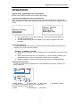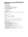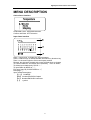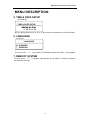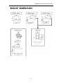
1
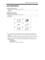
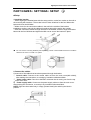
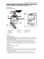
High Speed dome camera user manual
CONTENTS
MAIN FEATURES………………………………………………………………………………2
PRECAUTIONS…………………………………………………………………………………3
ACCESSORIES…………………………………………………………………………………4
PART NAMES • SETTINGS • SETUP①
①(TC3032)…………………..…….……………5
PART NAMES • SETTINGS • SETUP②
②(TC3032) ……………………………………..9
PART NAMES • SETTINGS • SETUP③
③(TC3032) ……………………………………13
CONNECTIONS ……………………………………………………………………………… 15
OPERATION……………………………………………………………………………………16
MENU DESCRIPTION ………………………………………………………………………19
1.SYSTEM INFORMATION ……………………………………………………….……… 22
2.DISPLAY SETTINGS …………………………………………………………….……… 22
3.DOME SETTINGS …………………………………………………………….…………26
4.PASSWORD SETTINGS …………………………………………………………………40
5.TIME AND DATE SETTINGS ………………………………………………….…………41
6.SYSTEM LANGUAGE OPTION …………………………………………………………41
7.REBOOT SYSTEM…………………………………………………………………………41
MOUNT DIMENSION ………………………………………………………………………… 42
SPECIFICATIONS ……………………………………………………………………………43
1
High Speed dome camera user manual
MAIN FEATURES
● Remote updating the firmware of speed dome by RS485 bus
● It can set software ID, to support broadcast ID function.
● Automatically identify PEAMRAIN protocol or PELCO D/P protocol
● The dome can automatically identify SANYO,SONY,HITACHI series camera module.
● With function of auto focus, auto iris, auto white balance and auto backlight
compensation etc. to have clear camera scene at any time.
● Built-in linear power for anti-surge and anti-Lightning protection
● According to application, with parts for alarm, wand-proof housing, shield, smoked
cover, available
● Built-in function of protocol converter, to support RS485 communication and
Manchester code.
● Preset position storage function, it can save 256 preset.
● 8 cruise tour, every tour can call 32 preset.
● 4 Pattern tour, to save the scan route by joystick.
● With automatic scan function, the scope of two limits can be planar scanned gradually,
the scanning steps of the limits are optional.
● Automatic recover to movement before power failure.
● Time startup function, to start the movement in the time table have set.
● Power-up action, preset, cruise tour, pattern tour, auto scan, etc. available
● Park action. preset, cruise tour, pattern tour, auto scan, etc. available
● 360°continous panning.
● -5°~90°tilting rotation, automatic flip function, continuous tilting between -5°to
185°.
● Privacy masking function, maximum 24 masking zone available.
● Limit setting, to set the pan or tilt movement in a scope.
● It can display Temperature, angle, direction, zoom, etc.
● English user menu
2
High Speed dome camera user manual
PRECAUTIONS
■In case of problem
●Do not use the unit if smoke or a strange odor comes from the unit, or if it seems not to
function correctly. Turn off the power immediately and disconnect the power cord, and
then consult your dealer or an Authorized Sanyo Service Center.
■Do not open or modify
●Do not open the cabinet, as it may be dangerous and cause damage to the unit. For
repairs, consult your dealer or an Authorized Sanyo Service Center.
■Do not put objects inside the unit
●Make sure that no metal objects or flammable substance get inside the unit. If used with
a foreign object inside, it could cause a fire, a short-circuit or damage. Be careful to
protect the unit from rain, sea water, etc. If water or liquid gets inside the unit, turn off the
power immediately and disconnect the power cord, and then consult your dealer or an
Authorized Sanyo Service Center.
■Be careful when handling the unit
●To prevent damage, do not drop the unit or subject it to strong shock or vibration.
■Do not install this unit close to magnetic fields
●The magnetic fields may result in unstable operation.
■Protect from humidity and dust
●To prevent damage, do not install the unit where there is greasy smoke or steam, where
the humidity may get too high, or where there is a lot of dust.
■Protect from high temperatures
●Do not install close to stoves, or other heat sources, such as spotlights, etc., or where it
could be subject to direct sunlight, as this could cause deformation, discoloration or other
damages.
●Be careful when installing close to the ceiling, in a kitchen or boiler room, as the
temperature may rise to high levels.
■Cleaning
●Dirt can be removed from the cabinet by wiping it with a soft cloth. To remove stains,
wipe with a soft cloth moistened with a soft detergent solution and wrung dry, then dry by
wiping with a soft cloth.
●Do not use benzine, thinner or other chemical products on the cabinet, as this may
cause deformation and paint peeling. Before using a chemical cloth, make sure to read
all accompanying instructions. Make sure that no plastic or rubber material comes into
contact with the cabinet for a long period of time, as this may cause damage or paint
peeling.
3
High Speed dome camera user manual
ACCESSORIES
■ TC3032(
(Ceiling mount)
)
①Transparent cover installation screws (spare: 1)…………………………………………4
②Clamp fitting……………………………………………………………………..……………1
⑥Template ………………………………………………………...…………………………………… 1
■ TC3032(
(Indoor mount)
)
■ TC3032(
(Outdoor mount)
)
③Transparent cover installation screws (spare: 1)……………………….…………………1
④Lubricating oil…………………………………………………………………….……………1
⑤Sealing tape……………………………………………………………………………………1
★ The company may change due to improvements in product design and specifications,
manuals, if the change cause product can not match the user manual ,please follow the
product.
★ This brochure is owned the manufacturer, without permission of us, any unit or individual
shall in any form or means of reproduction parts of the manual and all the contents.
★
Beside usual functions, TC3032 Series High Speed dome with following function
can be selective,
Coaxial function;
Manchester control;
Alarm function(4ch inputs/2ch outputs)
4
High Speed dome camera user manual
PART NAMES • SETTINGS • SETUP
①
●Part Names
TC3032(Outdoor mount type)
)
①
④
⑦
⑩
Power supply cable
Main housing
Camera drive
Dome cover
●
Setup location
② Control cable
⑤ Base
⑧ position lock
③ Video output cable
⑥ Orientation slot
⑨ camera unit
Take the following points into consideration when setting up the camera
● The wall or ceiling used for installation should have enough strength to bear
approximately 4 times the combined weight of the camera and bracket. Select a wall or
ceiling that is strong enough to bear such a weight.
● Select a wall or ceiling surface that is completely flat, so that there will be no space
between the base of the bracket and the wall.
● Please ensure the positions should be in the scope, no object to block the camera.
■ SETTINGS
■ the dip-switch pillar to set protocol, Baud rate, address, etc., please follow the
manual in the drive unit to set, also can refer to followings,
1, Address settings(SW1 and SW2)
5
High Speed dome camera user manual
PART NAMES • SETTINGS • SETUP
①
SW 2
ON
D IP
1
2
3
4
5
6
P ro to c o l
B a u d ra te
7
8
A d d re s s
SW 1
ON
D IP
1
2
3
4
5
6
7
8
A d d re s s
Default setting:
Address: Dip-switch is all OFF, that is 0, it can control the dome by any address.
Protocol: Auto match, the dome can be controlled by PEARMAIN, PELCO P/D
Baud rate: 9600bps.
Address setup:
Address is set by Binary system, as following, to refer to last row of the address sheet,
sum of switch value of dips-switch is the address, e.g. 1, 3, 5 is ON, the switch value is is
1,4, 16, so the address is 1+4+16=21.
2, Address and Protocol:
SW1 Address
Dip Switch 1
2
3
4
5
6
7
8
Dip Switch
0
OFF OFF OFF OFF OFF OFF OFF OFF Auto-match
SW2 Protocol
1
2
3
4
5
6
OFF OFF OFF OFF OFF OFF
1
ON OFF OFF OFF OFF OFF OFF OFF PELCO P
ON OFF OFF OFF OFF OFF
2
OFF ON OFF OFF OFF OFF OFF OFF PELCO D
OFF ON OFF OFF OFF OFF
3
ON ON OFF OFF OFF OFF OFF OFF PEARMAIN
ON ON OFF OFF OFF OFF
OFF ON ON ON ON ON ON ON Sanyo
OFF OFF ON OFF OFF OFF
254
Switch Value
1
2
4
8
16
32
64 128 Manchester code ON OFF ON OFF OFF OFF
Samsung
OFF ON ON OFF OFF OFF
Address is 0, it can control the dome by any address.
Address is 255, 255 is broadcast address, any address of dome set, all the dome can be
controlled.
The dome supports Coaxial function, if it is coaxial, please set the protocol to Auto-match
If the dome don’t set the protocol, the dome will regard as “Auto-match”.
Please refer to manufacturer to confirm what other protocol the dome support.
If it set software address (set dome address in its menu), it will not follow other
address, address 0 and 255 is ineffective.
3, Baud rate:
SW2 Baud rate
Dip
7
8
Switch
2400
ON
OFF
4800
OFF
ON
9600
OFF
OFF
19200
ON
ON
6
High Speed dome camera user manual
PART NAMES • SETTINGS • SETUP
①
■Setup
1 Install the bracket.
①While aligning the bracket base with the setup position, make four marks on the wall at
the mounting bolt locations. Then make holes in these locations for the four M8 anchor
bolts and insert the M8 bolts.
②Make a hole for the connection cables in the wall in the middle of the bracket
installation surface, and pull the cables all together through the wall to the outside.
③Pass the connection cables through the hole in the bracket, and then align the bracket
base with the four M8 bolts and tighten the M8 nuts to secure the bracket in place.
● You can use the mounting brackets (sold separately) shown in the illustrations below to install the
camera to the corner of a wall or to a pillar.
2 Connect the cables.
Connect all of the cables that have been passed through the bracket.
① Control cable: Connect to the control cable out from the main cover(with shield),
After making the connection, to envelop by insulation rubberized fabric.
② Video output cable: Connect to the BNC connector that is coming out from the top
of the main cover.
③ Power supply cable: Connect to the power supply cable out from the main cover.
After making the connection, to envelop it by insulation rubberized fabric.
NOTE: Sign here be marked only in image, please identify the cable by the label in
practice.
7
High Speed dome camera user manual
PART NAMES • SETTINGS • SETUP
①
3 Install the main cover to the bracket.
Follow the arrow, to fix the dome housing B into the bracket A and tighten the screws.
4 Install the camera unit.
Fit the orientation slot of camera unit into the orientation slot of base, push down the
camera unit till the bolt is complete fitness. To check the camera if it is be locked, in case
the camera fall off.
5 Install the dome cover.
After spread lubricating oil to the edge of dome cover A, fit the dome cover into the main cover and
secure it by tightening the screws B.
Note: Be sure to remove the lens cap from the camera before installing the dome cover.
8
High Speed dome camera user manual
PART NAMES • SETTINGS • SETUP
②
PART NAMES
TC3032(
(indoor mount)
)
①
④
⑦
⑩
Power supply cable
Main cover
Camera drive
Dome cover
② Control cable
⑤ Base
⑧ position lock
③ Video output cable
⑥ Orientation slot
⑨ camera unit
■Setup
1 Install the bracket.
① While aligning the bracket base with the setup position, make four marks on the wall
at the mounting bolt locations. Then make holes in these locations for the four M8 anchor
bolts and insert the M8 bolts.
② Make a hole for the connection cables in the wall in the middle of the bracket
installation surface, and pull the cables all together through the wall to the outside.
③ Pass the connection cables through the hole in the bracket, and then align the bracket
base with the four M8 bolts and tighten the M8 nuts to secure the bracket in place.
■ Settings
Same settings according to aboves.
1 Install the bracket.
To the wall
①While aligning the bracket base with the setup position, make four marks on the wall at
the mounting bolt locations. Then make holes in these locations for the four M8 anchor
bolts and insert the M8 bolts.
② Make a hole for the connection cables in the wall in the middle of the bracket
installation surface, and pull the cables all together through the wall to the outside.
9
High Speed dome camera user manual
PART NAMES • SETTINGS • SETUP
②
③Pass the connection cables through the hole in the bracket, and then align the bracket
base with the four M8 bolts and tighten the M8 nuts to secure the bracket in place.
● You can use the mounting brackets (sold separately) shown in the illustrations below to
install the camera tothe corner of a wall or to a pillar.
Installation to a ceiling
①Loosen the bolts
of the bracket base, and then turn the bracket base to remove it.
②While aligning the bracket base with the setup position, make four marks on the ceiling
at the mounting bolt locations. Then make holes in these locations for the four M8 bolts
and insert the M8 bolts.
③Make a hole for the connection cables in the ceiling in the middle of the bracket
installation surface, and pull the cables all together through the ceiling to the outside. If
routing the cables along the surface of the ceiling, to use the cable groove
in the
bracket base.
④Pass the cables through the hole, and then follow the bracket base with the four M8
bolts and firmly tighten.
⑤After passing the connection cables through the bracket, firmly tighten the screws
.
10
High Speed dome camera user manual
PART NAMES • SETTINGS • SETUP
②
2 Connect the cables.
Connect all of the cables that have been passed through the bracket.
① Control cable: Connect to the control cable out from the main cover(with shield),
After
making the connection, to envelop by insulation rubberized fabric.
② Video output cable: Connect to the BNC connector that is coming out from the top
of the main cover.
③ Power supply cable: Connect to the power supply cable out from the main cover.
After making the connection, to envelop it by insulation rubberized fabric.
NOTE: Sign here be marked only in image, please identify the cable by the label in
practice.
3 Install the main cover to the bracket.
Wind the accessory waterproof sealing tape
around the connecting part of the main
cover, screw the main cover clockwise into the bracket, and then securely tighten the
screw .
TO the ceiling:
Install Main cover by clockwise into the base of bracket as followings, then tighten the
screws.
4 Install the camera unit.
Fit the orientation slot of camera unit into the orientation slot of base, push down the
camera unit till the bolt is complete fitness. To check the camera if it is be locked, in case
the camera fall off.
11
High Speed dome camera user manual
PART NAMES • SETTINGS • SETUP
②
5 Install the dome cover.
After spread lubricating oil to the edge of dome cover , fit the dome cover into the main
cover and secure it by tightening the screws .
Note: Be sure to remove the lens cap from the camera before installing the dome cover.
12
High Speed dome camera user manual
PART NAMES • SETTINGS • SETUP ③
■PART NAMES
TC3032(
(ceiling mount)
)
7
6
8
9
①
④
⑦
⑩
Power supply cable
Main cover
Camera drive
Dome cover
② Control cable
⑤ Base
⑧ position lock
③ Video output cable
⑥ Orientation slot
⑨ camera unit
■Setup
1 Install the bracket.
① While aligning the bracket base with the setup position, make four marks on the wall
at the mounting bolt locations. Then make holes in these locations for the four M8 anchor
bolts and insert the M8 bolts.
② Make a hole for the connection cables in the wall in the middle of the bracket
installation surface, and pull the cables all together through the wall to the outside.
③ Pass the connection cables through the hole in the bracket, and then align the bracket
base with the four M8 bolts and tighten the M8 nuts to secure the bracket in place.
■ Settings
Same settings according to aboves.
■ Setup
When installing the ceiling type camera (PE3030V3), please sign a position mark on the
ceiling by use of follows method, and drill a hole of 225mm diameter.
13
High Speed dome camera user manual
PART NAMES • SETTINGS • SETUP ③
Installation condition:
Ceiling thickness: 0.8cm(0.38 inch)- 4.2cm(1.65 inch).
Carrying capacity: 4 times of weight of camera.
1 Installing main cover to a ceiling
①Drill a hole of 225mm diameter in the position of ceiling.
②Pull out the three arm of main cover , and adjust it fitness to the thickness of the
ceiling, make it be locked of main cover.
2 Connect the cables.
Connect all of the cables that have been passed through the bracket.
①Control cable: Connect to the terminals on the connection board inside the main cover
(with shield), , to envelop by insulation rubberized fabric.
②Video output cable: Connect to the BNC connector that is coming out from the top of
the main cover.
③Power supply cable: Connect to the terminals on the connection board from the main
cover, to envelop by insulation rubberized fabric.
NOTE:
● Also you could connect the cables before embedding the main cover into ceiling. Adapt
the installation procedures in accordance with the circumstances.
●Sign here on the cables only be marked in the user manual, please recognize in
practice the cable by the label 0n it.
3 Install the camera unit.
Fit the orientation slot of camera unit into the orientation slot of base, push down the
camera unit till the bolt is complete fitness. To check the camera if it is be locked, in case
the camera fall off.
14
High Speed dome camera user manual
PART NAMES • SETTINGS • SETUP ③
4 Install the dome cover.
① install the dome cover drip-prevention wire A in between the main cover and the
dome cover.
② align the projections C on the dome cover with the slot
in the base of the main
cover, and then turn the dome cover to the right to secure it in place.
Note: Be sure to remove the lens cap from the camera before installing the dome cover.
15
High Speed dome camera user manual
CONNECTIONS
Turn off the power for all equipment before making these connections.
Read the instruction manuals for all of the equipment being connected. In addition, if the
cables are connected incorrectly, it may cause smoke or incorrect operation to occur.
▇ Connections for using RS-485 control
① Power supply cable(
(AC24V),
),to
), connect to 24VAC power supply.
② Video cable(75Ω),
,to connect to Monitor
③ Alarm inputs/output cable, 4ch alarm inputs and 2ch outputs, support NO/NC
alarm
Short circuit
alarm
Alarm inputs
①
N.O. Sensor
2.2K
②
③
④
NOTE:
2.2K
2.2K
2.2K
④ Communication cable, to connect to
RS485 A and B.
N.C. Sensor
G.N.D.
……
Remark: this connection can prevent short-circuit or
cut-off, it should connect in side of sensor, as N.O.
sensor connects a 2.2K resistance in parallel, N.C.
sensor connects a 2.2K resistance in series, to make
inputs be dis-alarm, if so, whether the sensor in N.C or
N.O, alarm will be triggered.
To the alarm inputs port doesn’t occupy, in order to
avoid error to trigger alarm, we suggest to connect 2.2K
resistance to mask.
X
Mask the inputs
Cut-off alarm
not occupied
If the camera and the system controller are
too far
Apart or overfull dome in same control
device, the reliability of the control signals
may drop.
as followings,
Consumable parts
The following parts are consumable parts.
In addition, the service life for each part will
vary depending on the operating
environment and conditions of use.
●Lens
●Slip ring
●FPC cable
·Dome movement can not follow the command.
·Other dome will follow the command in control
appointed dome.
If this happens, please use RS485 distributor,
120Ω Terminal resistance and check the cables
and signal transmission.
16
High Speed dome camera user manual
OPERATIONS
Speed dome operations by control device
Please refer to above for device connection and settings.
1 Connect all equipment and turn on the power.
When the power for the camera is turned on, the self-test function for the internal lens
starts, and when it finishes, the individual information for that camera is displayed on the
screen.
Memory self-testing…
SW1:10000100
SW2:00001001
Protocol: PELCO P
Buadrate: 4800
Dome address: 1
Camera type: Sony
…..
During self-testing, if the dome finds fault, it will stay on the fault period or
indicate error information.
The dip-switch setting in the self-testing is for factory inspection and user
checking.
2, To have keyboard
To refer to the keyboard manual, to check and have same protocol, baud rate and
address, then it can control the dome.
Exception of Address 0 and 255:
When dome address is 0, the controller chooses any address, it can control the
dome.
When dome address is 255, if the dome don’t set the software address (set
the address in the menu), any address of dome can be controlled
When set address in menu, the dome will only follow the software address.
3, Speed dome operation
To refer to user manual of speed dome, to have direction movement, zooming, iris,
focus, preset etc.
1, dome address
2, camera title
3, time & date
5, to display all movement name, alarm information
6, preset, preset number and title
7, zoom
8, Pan/tilt angle 9, Direction
17
4, temperature inside
High Speed dome camera user manual
OPERATIONS
4, Shortcut function
Pearmain protocol
1)
2)
3)
4)
5)
6)
Enter into OSD menu
Preset setup, calling and clear, maximum 128 preset.
Cruise tour setup, calling and clear, maximum 4 cruise.
Pattern tour setup and calling, maximum 4 pattern.
Automatic scan setup and calling
To stop automatic movement.
Pelco protocol
1) Enter into OSD menu
‘95’ + <preset>+‘95’ + <preset>
Please ensure that it can not insert any action or commend between ‘95’ + <preset>
and ‘95’ + <preset>.
2) Preset
Calling:‘n’ + <preset> n≤99
3) Automatic scan
Setup: ‘95’ + <preset>+ ‘92’+ <PRESET>
Calling:‘95’ + <preset>+ ‘99’+ <PRESET>
4) Cruise tour
Calling :‘95’+ <PRESET> + ‘97’+ <PRESET>, only 1 cruise tour available here.
5) Stop scan
‘95’+ <PRESET> +‘96’+ <PRESET> to stop all scan in auto priority.
NOTE: Above command can implement in menu, please refer to Menu description.
5, Advanced function
The dome support follow advanced function
1, Remote updating the firmware of speed dome by RS485 bus
2, network management function
It can inspect current dome information, as followings,
a. running normally or abnormally (it will indicate its abnormal running)
b. horizontal/vertical position, zoom
c. running status (usual running, preset, cruise, auto scan etc.)
d. temperature, time, total running time
e. absolute direction calling, it can accept the command with direction, zoom, to move
the direction by preset
f. relative direction calling, similar to absolute direction
above remote updating and Network management function must support semi-duplex
communication mode.
18
High Speed dome camera user manual
OPERATIONS
6, Quick query (details for attachment)
)
19
High Speed dome camera user manual
MENU DESCRIPTION
Different protocol with different commend to call OSD menu, commend of PEARMAIN
protocol is ‘99’ + <SHOT>,PELCO protocol is ‘95’ + <PRESET>+‘95’ + <PRESET>,
Following operation in menu.
Move cursor: UP/DOWN/LEFT/RIGHT;
Enter into sub menu: RIGHT direction;
Exit to superior menu, LEFT direction, if LEFT has been used, to take
CLOSE/OPEN;
To change numerical value: WIDE/TELE, UP/DOWN, preset calling.
Following is operation manual for the operation interface.
Usual interface
If menu with “…”, it indicate to have sub menu.
If menu title with“…”, it means not to display menu information by 1 screen, it can go to
next page by cursor.
…
-----------------------DOME SETUP
√CAM PARAMETER SETUP …
… OFF
DOME TITLE SETUP
…
DOME ADDRESS SETUP
MOVEMENT SETUP …
PRESET SETUP …
UP/DOWN cursor: UP/DOWN direction
Enter into sub menu: RIGHT direction
Back to superior menu: LEFT direction
Interface with clue
To follow the clue to operate step by step, e.g. the interface to control dome movement
setup, e.g. Pattern, horizontal limit etc
To confirm to press〈OPEN〉and cancel by〈CLOSE〉
Increase/decrease frame interface
To increase numerical value: WIDE or UP direction
To decrease numerical value: TELE or DOWN direction
Shortcut key: to call preset (1 to 80 is available)
Exit the interface: CLOSE or LEFT direction
20
High Speed dome camera user manual
MENU DESCRIPTION
Choice frame interface
UP/DOWN cursor: UP/DOWN direction
Confirm and Back: LEFT direction
Input frame interface
Zone 1: target zone, to display the input character.
Zone 2: choice zone, to choose wanted information by direction key.
Zone 3: to choose English or China and inputs method
Remark: the character dwelled with cursor will flash, then to choose.
To confirm character, and switch input method by TELE or WIDE;
To delete input character by FAR or “←”
To input Blank by NEAR or “ ”;
Exit input frame by CLOSE/OPEN or “√”;
Next page: “↓”
Input method description.:
【中文】 CHINESE
【EN】 Number/ENGLISH Capital
【en】 Number/ENGLISH lowercase
【,.】 symbol
21
High Speed dome camera user manual
MENU DESCRIPTION
MAIN MENU
OSD menu including 7 sub menu: System information, Display setup, Dome setup,
Password setup, Time & date setup, Language, setup, Reboot system, as followings,
MAIN MENU
-----------------------√System info.
Display setup
Dome setup
Password setup
Time & date setup
Language
Reboot system
To move cursor (“√”) by joystick UP or DOWN to proper sub menu, to press right
direction key to enter the sub menu, left key to exit.
Followings is detailed description of sub menus.
SYSTEM INFO.( SYSTEM INFORMATION):
:
To check system information of current dome, including product number, product date,
product ID series, firmware version, protocol, address, baud rate, camera type, total run
time, auxiliary switcher, alarm information, etc., it only for check information, can not
revise.
DISPLAY SETUP:
:
To set screen display information, including camera title, preset title, pattern title, cruise
tour title, angle, zoom, alarm information, direction, dome address, time & date,
temperature, display setup etc.
DOME SETUP:
:
To set the dome parameter, including movement setup, preset setup, cruise setup,
pattern setup, time-start setup, privacy mask setup, alarm setup, camera setup,
initialization setup etc.
PASSWORD SETUP:
:
To set dome password, including, password enable, input and revision.
TIME & DATE SETUP:
:
To set time and date of dome, including YEAR, MONTH, DATE, HOUR, MINUTES, etc.
LANGUAGE SETUP:
:
To set language of dome, currently CHINESE and ENGLISH available.
REBOOT SYSTEM:
:
To reboot system without power 0ff, the information will not lose.
22
High Speed dome camera user manual
MENU DESCRIPTION
1, SYSTEM INFORMATION
System info. …
-----------------------√PRODUCT MODEL
PRODUCT DATE
PRODUCT SERIES
VERSION NO.
PROTOCOL
DOME ID
BAUD RATE
CAM TYPE
TOTAL RUN TIME
AUX SWITCH
ALARM INFO.
TC3030
070700
000001
V2.00
PE
3
9600
SONY
0 h
1020
OFF
It displays main information of current camera, Product model, product date, product
series, version no. have been set in initialization status, Protocol, Baud rate is from
dip-switch pillar, Dome ID is from dip-switch pillar set or firmware set, camera type is the
camera module in the dome, Total run time is to display total run time from initialization,
AUX (Auxiliary) switch, Alarm info. Is to display alarm information. Left direction key to
exit.
2, DISPLAY SETUP
DISPLAY SETUP
----------------√DOME TITLE
DIS
PRESET TITLE
ENA
PATTERN TITLE
ENA
CRUISE TITLE
ENA
ANGLE
ENA
ZOOM
ENA
ALARM
DIS
DIRECTION
DIS
DOME ADDRESS DIS
TIME & DATE
DIS
TEMPERATURE
AUTO
DISPLAY SETUP
ENA
DISPLAY POSITION ….
To move cursor (“√”) by joystick UP or DOWN to proper sub menu, to press left/right
direction key to exit.
When enter into sub menu, to change whether display current information by joystick UP
or DOWN.
23
High Speed dome camera user manual
MENU DESCRIPTION
IMPORTANT:ENA in above is abbreviation of ENABLE, DIS is abbreviation of DISABLE,
will not explain again in followings.
Followings is sub menus.
A. CAMERA TITLE:
:
To refer to fig.2
CAMERA TITLE
---------------------------|√ | DIS
| | ENA
B. PRESET TITLE:
To refer to fig.7
PRESET TITLE
---------------------------| |DIS
|√ |ENA
C. PATTERN TITLE:
To refer to fig.6
PATTERN TITLE
---------------------------| |DIS
|√ |ENA
D. CRUISE TOUR TITLE:
To refer to fig.6
CRUISE TITLE
---------------------------| |DIS
|√ |ENA
E. ANGLE:
To refer to fig.9
ANGLE
---------------------------| |DIS
|√ |ENA
24
High Speed dome camera user manual
MENU DESCRIPTION
F. ZOOM:
:
To refer to fig.8
ZOOM
---------------------------| |DIS
|√ |ENA
G. ALARM:
to display alarm information.
ALARM
---------------------------| |DIS
|√ |ENA
H. DIRECTION:
To refer to fig.10
DIRECTION
-----------------------|√|DIS
| |ENA
I. DOME ADDRESS:
To refer to fig.1
DOME ADDRESS
---------------------------|√ |DIS
| |ENA
J. TIME & DATE:
To refer to fig.3,4
TIME & DATE
---------------------------|√ |DIS
| |ENA
25
High Speed dome camera user manual
MENU DESCRIPTION
K. TEMPERATURE:
:
To refer to fig.5
TEMPERATURE
---------------------------|√ |AUTO
| |DIS
| |ENA
If in ‘AUTO’, the temperature will display on screen only the temperature inside of dome
is higher 70℃
L. DISPLAY SETUP
DISPLAY SETUP
---------------------------| |DIS
|√ |ENA
To set whether display or not all information on screen, if set in DIS, no information will
display on screen, if want to display the parameters, please set ENA of DISPLAY
SETUP first.
M. DISPLAY POSITION SETUP:
DISPLAY POSITION SETUP
-----------------------√DOME ADDRESS
DOME TIME & DATE
DOME TITLE
It’s to set display position of dome ID, time & date, camera title on screen, right direction
key to enter in the interface, to fix the display position by direction key, then to press
<OPEN> to save and exit, <CLOSE> to give up.
26
High Speed dome camera user manual
MENU DESCRIPTION
3, Dome setup
DOME SETUP …
-----------------------√CAM PARAMETER SETUP …
DOME TITLE SETUP
DOME ADDRESS SETUP OFF
MOVEMENT SETUP …
PRESET SETUP …
AUTO SCAN SETUP
…
CRUISE SETUP
…
PATTERN SETUP
…
TIME START SETUP
MASK SETUP
…
ALARM SETUP
…
INITIALIZATION SETUP …
To move cursor (“√”) by joystick UP or DOWN to proper sub menu, to press right
direction key to enter and left direction key to exit.
Followings is detailed description to its sub-menu.
A.
CAM (CAMERA) PARAMETER SETUP:
:
To set camera parameter, including BLC (Backlight compensation), White balance,
Auto Iris, Auto focus, digital zoom, color & B/W mode, Anti-shake and camera type etc.
CAM PARAMETER SETUP …
-----------------------√DIGITAL ZOOM
BLC
WHITE BALANCE
IRIS
FOCUS
COLOR B/W MODE
ANTI-SHAKE
CAMERA TYPE
DIS
DIS
…
AUTO
AUTO
AUTO
ENA
To move cursor (“√”) by joystick UP or DOWN to proper sub menu, to press right
direction key to enter and left direction key to exit.
27
High Speed dome camera user manual
MENU DESCRIPTION
DIGITAL ZOOM:
:
DIGITAL ZOOM
---------------------------|√ |DIS
| |ENA
To choose whether start digital zoom, if in DIS, digital zoom is off, so the camera is only
with optical zoom, if choose to run digital zoom, it will have it on optical zoom.
BLC (Backlight compensation):
:
BLC
---------------------------|√ |DIS
| |ENA
To choose BLC on or off
WHITE BALANCE:
:
WHITE BALANCE …
-----------------------√SYSTEM INFO.
R GAIN
G GAIN
AUTO
DIS or ENA is to set WHITE BALANCE to auto or manual, before adjust G GAIN or R
GAIN, to set to DIS first.
IRIS:
:
IRIS
---------------------------| |DIS
|√ |ENA
Iris DIS and ENA is to set auto IRIS or manual IRIS.
FOCUS MODE:
:
FOCUS MODE
---------------------------| |MANUAL
|√ |AUTO
Manual or Auto FOCUS is to set focus mode to be manual or automatic.
28
High Speed dome camera user manual
MENU DESCRIPTION
COLOR & B/W MODE
COLOR & B/W MODE
---------------------------|√ |AUTO MODE
| |COLOR MODE
| |B/W MODE
Auto mode is to set camera can automatically switch between color and B/W according
to light, if in Color mode, the camera only will be in color and will not switch, if in B/W
mode, the camera will keep in B/W mode.
ANTI-SHAKE:
:
ANTI-SHAKE
-----------------------| |DIS
|√|ENA
DIS and ENA of ANTI-SHAKE is to trigger or not function of ANTI-SHAKE.
CAMERA TYPE:
:
CAMERA TYPE
-----------------------| |SONY
|√|SONY
980
480
The camera can recognize camera series, According to the camera series, it can choose
the model number to match the camera inside.
B. CAMERA TITLE SETUP:
:
To set current dome title, details setup to refer to input frame operation, display position
of camera title refers to fig.2
C. CAMERA ADDRESS SETUP:
:
Address set by menu of camera address is firmware address, effective from 1~9999, if
firmware address is 0000, the dome auto recognize the firmware address is close, the
dome will follow the hardware address, if not, follow the firmware address.
Dome address
-----------------------0000
-----------------------↑↓to change value
,←→to change position
29
High Speed dome camera user manual
MENU DESCRIPTION
D. MOVEMENT SETUP
Including auto flip, speed match, power-on action, park action, manual limit, auto scan
setup, north setup, etc.
MOVEMENT SETUP
…
-----------------------√AUTO FLIP
ENA
SPEED MATCH
ENA
AUTO ELEVATION ENA
NO
POWER UP
PARK ACTION
…
…
MANUAL LIMIT SETUP
NORTH SETUP
PRIORITY SETUP
MAN
To move cursor (“√”) by joystick UP or DOWN to proper sub menu, to press right
direction key to enter and left direction key to exit, followings is sub menu of
MOVEMENT SETUP.
AUTO FLIP:
:
AUTO FLIP
---------------------------| |DIS
|√ |ENA
When lens is in vertical position and keep pressing, camera whether will auto flip flatly
180° and continue to vertical movement, DIS and ENA to set auto flip.
180° flip
→
→
SPEED MATCH:
:
SPEED MATCH
---------------------------| |DIS
|√ |ENA
‘DIS’ is to set movement speed will slow while zoom in, “DIS” is to set movement is
nothing to zoom.
30
High Speed dome camera user manual
MENU DESCRIPTION
AUTO ELEVATION:
:
AUTO ELEVATION
-----------------------| |DIS
|√|ENA
If in ENA of AUTO elevation, when dome moves to limit, the dome can enlarge limit
scope according to zoom in times, to ensure the scene will not limit according zoom in.
POWER UP ACTION:
:
POWER UP ACTION
-----------------------|√|NO ACTION
| |PRESET
| |CRUISE
| |PATTERN
| |AUTO SCAN
| |RECOVER
It’s to set power on action of speed dome after self-testing, NO ACTION is to keep
stillness, if in RECOVER, once power on, the dome will implement action before power
off, also, it can recover to cruise tour, pattern, auto scan, other actions of dome will be
default 1.
PARK ACTION:
:
PARK ACTION …
-----------------------√DWELL TIME
ACTION
2
NO
DWELL time is to set time, right key to enter into a time frame, details to refer to time
frame. Park action is to set action or not in the period not to move the dome.
ACTION of PARK available as followings,
31
High Speed dome camera user manual
MENU DESCRIPTION
PARK ACTION
---------------------------√ NO ACTION
PRESET
CRUISE
PATTERN
AUTO SCAN
TIME START
NO ACTION is to keep stillness, PRESET is to call preset 1, CRUISE TOUR,
PATTERN and AUTO SCAN is 3 different action, Cruise tour and Pattern is to
implement action 1 .
MANUAL LIMIT:
:
To set a horizontal zone, to limit all manual operation in this area.
MANUAL LIMIT SETUP
-----------------------√HORIZONTAL LIMIT
DIS
HORIZONTAL LIMIT SETUP
VERTICAL LIMIT SETUP
LIMIT INFO.
To move cursor (“√”) by joystick UP or DOWN to proper sub menu, to press right
direction key to enter and left direction key to exit.
MANUAL LIMIT can set whether start up this function by DIS or ENA, HORIZONTAL
LIMIT SETUP and VERTICAL LIMIT SETUP is to set LIMIT scope, Move cursor to
LIMIT start bit to press <OPEN> and to terminal by <CLOSE> to confirm and exit, if
MANUAL LIMIT has been set before, if want to change, it will jump out a frame to ask
whether to cover previous LIMIT settings, LIMIT INFO. Is to check LIMIT details, e.g.
HORIZONTAL LIMIT start bit and terminal.
NORTH SETUP
Right key to enter, move dome to the NORTH by direction key, <OPEN> to confirm,
then the dome will regard this position as NORTH, NORTH will be the angle start bit.
PRIORITY:
:
PRIORITY
-----------------------|√|MANUAL
| |AUTO
To set Priority of advanced movement and manual control, if in MANUAL, when to
move advanced movement, manual operation can stop it, if in AUTO, only proper
commend can stop the running advanced movement.
32
High Speed dome camera user manual
MENU DESCRIPTION
E. PRESET SETUP:
:
To set preset and its correlative function, including PRESET NO., PRESET STATUS,
SET PRESET, EDIT TITLE, CLEAR CURRENT PRESET, CLEAR ALL PRESET, etc. as
followings.
PRESET SETUP
---------------------------√ PRESET NO
1
STATUS
NO
SETUP
TITLE EDIT
CLEAR CURRENT
CLEAR ALL
To move cursor (“√”) by joystick UP or DOWN to proper sub menu, to press right
direction key to enter and left direction key to exit.
PRESET NO. :
PRESET NO.
1
--------------------------【 WIDE】 ↑ 【 TELE】 ↓
--------------------------EFFECTIVE FROM 1-128
It is effective to set 1 to 128 preset, if in Pleco protocol, only 99 effective preset can set.
PRESET STATUS:
:
To check current preset status.
PRESET SETUP:
:
To move lens to a position by joystick, to press <OPEN> to confirm setup, it will automatically
exit to menu of PRESET SETU
TITLE EDIT:
:
XXX_
---------------------------01234567890
ABCDEFGHIJK
LMNOPQRSTUV
WXYZ
● ←
-------------------------------------
【 EN】
To edit a title for the preset, it will be on screen, when the preset is calling, it will be a
frame as above, detailed operation please refer to INPUT FRAME.
33
High Speed dome camera user manual
MENU DESCRIPTION
CLEAR CURRENT:
:
To clear current preset setup and its title.
CLEAR ALL:
:
To clear all preset setup and its title.
F. AUTO SCAN SETUP:
As followings:
AUTO SCAN SETUP
-----------------------√SCAN SETUP
INFORMATION
SPEED SETUP
DWELL TIME
STEP SETUP
20
2
1
To move cursor (“√”) by joystick UP or DOWN to proper sub menu, to press right
direction key to enter to revise parameter or setup status and left direction key to exit.
SCAN SETUP
Right direction key to enter the setup interface, <CLOSE> to exit and keep previous
settings, to move to the start bit by joystick (upper left corner of auto scan scope), to
press <OPEN> to set, and then to move to right upper corner to confirm terminal, which
is on lower right corner, < OPEN > to set, it will automatically exit to interface of SCAN
SETUP.
start
1
2
3
Terminal
SCAN INFORMATION
To check setup of AUTO SCAN, including horizontal and vertical information.
SCAN SPEED
To set motor speed in AUTO SCAN, right direction key to enter into operation interface,
it will display a frame to set motor speed, effective from 20~60.
SCAN DWELL TIME
To set running time from start to terminal, to press right direction key to have a frame to
set the time, effective from 1 to 10.
SCAN STEP SETUP
To set steps from start to terminal.
34
High Speed dome camera user manual
MENU DESCRIPTION
G. CRUISE TOUR SETUP:
:
As following:
CRUISE SETUP …
-----------------------√CRUISE NO.
STATUS SETUP
TIME SETUP
SETUP
TITLE SETUP
MAX.SPEED
RUN MODE
CLEAR CURRENT
CLEAR ALL
1
NO
0
112
SEQ
To move cursor (“√”) by joystick UP or DOWN to proper sub menu, to press right
direction key to enter to revise parameter or setup status and left direction key to exit.
CRUISE TOUR NO:
:
CRUISE NO.
1
--------------------------【 WIDE】 ↑
【 TELE】 ↓
--------------------------EFFECTIVE FROM 1-4
Effective from 1 to 4, it can set 4 tours.
CRUISE TOUR STATUS:
:
To check setup information of cruise.
CRUISE TOUR TIME SETUP:
:
To set dwell time during presets, refer to time frame operation
CRUISE TOUR SETUP:
:
CRUISE 1
---------------------------001→002→003→
→010→
→020→
→070
100→101→XXX→XXX→XXX→XXXX
XX→XXX→XXX→XXX→XXX→XXXX
XX→XXX→XXX→XXX→XXX→XXXX
XX→XXX→XXX→XXX→XXX→XXXX
XX→XXX
Number in above is preset no. of current cruise, to fix number by joystick, effective
preset is 1 to 128, XXX is the preset number, ‘X’ + <SET> <ENTER> to change preset
35
High Speed dome camera user manual
MENU DESCRIPTION
number, or <WIDE> to increase , <TELE> to decrease preset no., <CLOSE> to confirm
and exit after setup.
EDIT CRUISE TOUR TITLE:
:
To set a title for current cruise, when enter into title edition, there is a input frame,
details for input frame operation.
MAX. SPEED:
:
To set maximum speed for cruise.
As above figure, the cruise tour contains 9 presets, the speed set can make the cruise
smooth.
RUNNING MODE:
:
There are SEQ (in sequence) and RETURN available for application, In sequence, it
run from preset 1 to last effective preset, TETURN is to run from preset 1 to last preset,
then from last one to preset 1.
CLEAR CURRENT (CRUISE):
:
To clear current cruise tour and its title.
CLEAR ALL (CRUISE):
:
To clear all cruise tour and its title.
H. PATTERN SETUP :
To set PATTERN TOUR and its correlative functions, including, number of pattern setup,
Status, setup, edit title, clear current pattern, clear all pattern, etc., as followings,
PATTERN SETUP
---------------------------√ PATTERN NO
1
STATUS
NO
SETUP
TITLE EDIT
CLEAR CURRENT
CLEAR ALL
To move cursor (“√”) by joystick UP or DOWN to proper sub menu, to press right
direction key to enter to revise parameter or setup status and left direction key to exit.
36
High Speed dome camera user manual
MENU DESCRIPTION
PATTERN NO.:
:
PATTERN NO
1
--------------------------【 WIDE】 ↑ 【 TELE】 ↓
--------------------------EFFECTIVE 1-4
Effective from 1 to 4, it can set maximum 4 pattern, details to operate to refer to frame
operation.
PATTERN STATUS:
:
To check current pattern setup information.
PATTERN SETUP:
:
To steer lens by joystick, to choose Start bit of current pattern, <OPEN> to begin to
record the movement, when movement to terminal, <OPEN> to confirm and end the
setup, it can insert preset during pattern, commend of ‘X’+ <SET> + <ENTER> to insert
the preset, ‘X’ is number of preset.
EDIT PATTERN TITLE:
:
To edit a pattern title, details to refer to input frame.
CLEAR CURRENT PATTERN:
:
To clear current pattern and its title.
CLEAR ALL PATTERN:
:
To clear all pattern and its title.
I. TIME START SETUP:
:
To set dome timing, as followings,
1 08:30-09:00
2 00:00-00:00
3 00:00-00:00
4 00:00-00:00
5 00:00-00:00
6 00:00-00:00
7 00:00-00:00
8 00:00-00:00
CRUISE 001
NO ACTION 001
NO ACTION 001
NO ACTION 001
NO ACTION 001
NO ACTION 001
NO ACTION 001
NO ACTION 001
To set by joystick, to set time scope, action and number, <TELE>, <WIDE> to revise
parameter, and ‘X’ +<SET>+<ENTER> to revise number, <CLOSE> to exit.
J. PRIVACY ZONE MASKING:
:
When in a rectangle scope of camera scene is of privacy zone, it can mask this scope,
when camera scan to this scope, the masking zone will be a color has been set.
This menu including mask no., setup, color, clear all privacy zone etc., as followings,
37
High Speed dome camera user manual
MENU DESCRIPTION
PRIVACY MASK
---------------------------√ MASK NO
1
SCOPE SETUP
MASK COLOR
0
CLEAR CURRENT
CLEAR ALL
To move cursor (“√”) by joystick UP or DOWN to proper sub menu, to press right
direction
key to enter to revise parameter or setup status and left direction key to exit.
MASK NO.:
:
MASK NO
1
--------------------------【 WIDE】 ↑ 【 TELE】 ↓
--------------------------EFFECTIVE FROM 1-4
The mask effective number will be change according to camera, refer to Frame for
details.
PRIVACY MASK ZONE SETUP:
:
To fix the zone want to be masked by joystick, right direction key to setup sub menu, to
set length, width of Mask zone or clear current Mask setup, to “PRIVACY MASK
LENGTH SETUP” or “PRIVACY MASK WIDTH SETUP” by joystick, <OPEN> to enter
into setup, there is a interface of a Frame, refer to Frame operation.
MASK COLOR SETUP:
:
MASK COLOR SETUP
0
--------------------------【 WIDE】 ↑
【 TELE】 ↓
--------------------------EFFECTIVE IS 0
Different camera with different color.
CLEAR ALL MASK:
:
To clear all mask zone.
K. ALARM SETUP:
:
The dome supports 4ch alarm signal inputs and 2ch switch outputs (24V/1A), this sub
menu is details for alarm settings, alarm signal inputs to refer to “CONNECTION” in
above.
Note: alarm is only available alarm enable of any alarm zone, it will run alarm outputs when alarm being
triggered, to call preset.
If alarm information set to be “display”, when alarm being triggered, following information will display
on scene.
38
High Speed dome camera user manual
MENU DESCRIPTION
Alarm 3 is to mean alarm being triggered on alarm zone 3.
Alarm signal inputs is switch value, it supports NO and NC, refer to
“CONNECTION ” for details.
Alarm outputs is switch value, it can output automatically after alarm trigger, also it
can control manually by keyboard “AUX. switch”, it is AUX. switch 1 and 2.
This menu is to set alarm input/output time, and alarm enabling setup, as followings
ALARM SETUP
-----------------------√ ACTION …
DIS
RECOVER
TIME
2
TRIGGER TYPE NO
IND
STATUS
Alarm action is to set enabling, output switch and alarm running preset of the 4 inputs
alarm.
ALARM ACTION:
:
ALARM ACTION
-----------------------√NUMBER
PRESET
ENABLE STATUS
AUX SWITCHER
1
1
NO
NO
Number is alarm number, to set alarm during alarm zone of all 4 alarm inputs.
PRESET here is to call preset when alarm being triggered.
ENABLE STATUS is to set the alarm enable or disable.
AUX (auxiliary) SWITHER is to set alarm output, with AUX1 and AUX2 two outputs, if
set to NO ACTION, when alarm being triggered, it only will call preset, will not output
alarm information.
39
High Speed dome camera user manual
MENU DESCRIPTION
RECOVER:
:
RECOVER
-----------------------|√|DIS
| |ENA
It is to set whether to recover the action or not, before alarm being triggered
ALARM SWITCH TIME:
:
It is to set alarm preset switch time, when 2 or above alarm being triggered at same
time, effective is from 2 to 60 seconds, detailed operation is to refer to Frame operation
ALARM TRIGGER TYPE:
:
TRIGGER TYPE
----------------------------------------------|√|NO
| |NC
In “NO”, alarm output AUX1A and AUX 1B (AUX2A and AUX2B) is in disconnection
when no alarm being triggered, other way around, if in “NC”, the AUX1A and AUX 1B
(AUX2A and AUX2B) is in connection.
ALARM ENABLE TYPE:
:
ENABLE TYPE
-----------------------|√|INDIVIDUAL
| |ALL ENA
| |ALL DIS
There are 3 types, INDIVIDUAL is set alarm on or off according to each alarm input.
ALL ENA and ALL DIS is to set all 4ch alarm on or off.
L. INITIALIZATION RECOVER
To recover the dome to initialization setup.
INITIALIZATION RECOVER
---------------------------√ RECOVER ALL PARA
CLEAR ALL
To move cursor (“√”) by joystick UP or DOWN to proper sub menu, to press right
direction key to enter to revise parameter or setup status and left direction key to exit.
RECOVER ALL PARA(parameter) is to recover all parameter to initialization setup.
CLEAR ALL is to clear all data and parameter. 。
40
High Speed dome camera user manual
MENU DESCRIPTION
4, PASSWORD SETUP
As followings:
PASSWORD SETUP
-----------------------√SETUP
REVISE
DIS
To move cursor (“√”) by joystick UP or DOWN to proper sub menu, to press right
direction key to enter into the interface, as followings,
A. PASSWORD SETUP:
:
As followings:
SETUP
---------------------------|√ |DIS
| |ENA
Joystick UP or DOWN to set password or not, ENA is to set, to change menu parameter
by
password, if it wants to change parameter without password inputs, followings frame will
be out.
PASSWORD TO REVISE
-----------------------|√|INPUT
| |EXIT
INPUT is to input the password, press left direction key to the input Frame.
EXIT is exit to senior menu.
The password can be number and character, after input, <CLOSE> to confirm, if
incorrect, it will clue to incorrect password.
C. PASSWORD REVISE:
The password can be number and character, input Frame for password input,
<CLOSE> to exit.
Note: Initialization password is blank, please set new password before setting. If user
loses the password, please refer to manufacturer.
41
High Speed dome camera user manual
MENU DESCRIPTION
5. TIME & DATE SETUP
As followings:
TIME & DATE SETUP
-----------------------20002000-00-01 23:
23:41
Y M D H M
By left, right direction key to Y, M, D, H, M to revise the parameter by UP and DOWN.
6. LANGUAGE
As followings:
LANGUAGE
---------------------------|√ |CHINESE
| |ENGLISH
To move cursor (“√”) by joystick UP or DOWN to proper sub menu, to set laguage.
7. REBOOT SYSTEM
To move cursor (“√”) by joystick, right direction key to reboot, it is same to power-on,
the dome will self-test.
42
High Speed dome camera user manual
MOUNT DIMENSION
43
High Speed dome camera user manual
SPECIFICATIONS
TV format
Scanning method
Image sensor
Interlacing
Valid pixels
Synchronization
method
Horizontal resolution
Video signal output
terminal
S/N ratio
Lens (F1.6 – 3.8)
Rotation range
Rotation speed
Zoom speed
Electronic zoom
speed
Joystick auto
Automatic focus
Automatic iris
Iris level
Day/night
Camera
Electronic sensitivity
up
Electronic shutter
White balance
Backlight
compensation
AGC gain
Camera title
Privacy masking
Automatic mode
Preset position
Communication
format
Operating
environment
PAL/NTSC format compliant
According to camera module
Automatic white balance (ATW)/manual white balance (MWB)
Center-weighted average metering (OFF/ON)
ON (fixed)
No. of setting characters: Max.20, Display toggled off/on using
screen display function
Up to 4 privacy masks can be set on-screen / Mask display on/off
toggle
4 modes (Automatic scan, Cruise tour, Pattern tour, Preset
position)
128 position settings
RS—485 control
TC3032 (indoor ceiling, indoor pendant)
Temperature: 0° – +40°C, Humidity: 90% R.H. or lowe r
TC3032 outdoor ,Temperature: –20° – +50°C,
Humidity: 90% R.H. or lower (maintained by heater and blower)
24 V AC ±10%, 50 Hz (Power supply terminal: on connection
board)
Power consumption TC3032 (indoor ceiling, indoor pendant) : 10W
TC3032 outdoor: 10W, 35W (heater on)
Power supply
44