1
www.keithley.com
research
n
nanotechnology
n
semiconductor
n
wireless
www.keithley.com
n
electronic components
research
Test & Measurement
All other trademarks and trade names are the property of their respective companies.
A Greater Measure of Confidence
KEITHLEY INSTRUMENTS, INC. ■ 28775 AURORA RD. ■ CLEVELAND, OH 44139-1891 ■ 440-248-0400 ■ Fax: 440-248-6168 ■ 1-888-KEITHLEY ■ www.keithley.com
© Copyright 2013 Keithley Instruments, Inc.
nanotechnology
n
semiconductor
No. 2184 / Jan.13
n
wireless
n
electronic components
Test & Measurement
product catalog
product catalog
Specifications are subject to change without notice. All Keithley trademarks and trade names are the property of Keithley Instruments, Inc.
n
A Greater Measure of Confidence
Low Level Measurements and Sourcing
Low Voltage/Low Resistance Measurements
Technical Information . . . . . . . . . . . . . . . . . . . . . . . 110
Selector Guide . . . . . . . . . . . . . . . . . . . . . . . . . . . . . 114
2182ANanovoltmeter . . . . . . . . . . . . . . . . . . . . . . . . . . . . . 115
6220
DC Current Source . . . . . . . . . . . . . . . . . . . . . . . . . . 121
6221
AC and DC Current Source . . . . . . . . . . . . . . . . . . . 121
Series 3700A
System Switch/Multimeter and Plug-In Cards . . . . 126
Technical Information . . . . . . . . . . . . . . . . . . . . . . . 127
Selector Guide . . . . . . . . . . . . . . . . . . . . . . . . . . . . . 129
6482
Dual-Channel Picoammeter/Voltage Source . . . . . 131
6485Picoammeter . . . . . . . . . . . . . . . . . . . . . . . . . . . . . . . 134
6487
Picoammeter/Voltage Source . . . . . . . . . . . . . . . . . 137
2502
Dual-Channel Picoammeter . . . . . . . . . . . . . . . . . . . 141
6514
Programmable Electrometer . . . . . . . . . . . . . . . . . . 144
6517B
Electrometer/High Resistance Meter . . . . . . . . . . . 148
6521
Low Current, 10-channel Scanner Card
(for Model 6517x Electrometer) . . . . . . . . . . . . . . . 152
6522
Low Current, High Impedance Voltage,
High Resistance, 10-channel Scanner
Card (for Model 6517x Electrometer) . . . . . . . . . . 152
6220/6514/2000/7001
High Impedance Semiconductor Resistivity
and Hall Effect Test Configurations . . . . . . . . . . . . . 153
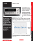
Arbitrary Waveform/Function Generator
3390
50MHz Arbitrary Waveform/Function Generator . . 154
1.888.KEITHLEY (U.S. only)
www.keithley.com
A Greater Measure of Confidence
LOW LEVEL MEASURE & SOURCE
Low Current/High Resistance Measurements
109
Technical information: Low voltage/low resistance measurement products
Technical
Information
How to Select a Voltmeter
Many kinds of instruments can measure voltage,
including digital multimeters (DMMs), electrometers,
and nanovoltmeters. Making voltage measurements
successfully requires a voltmeter with significantly
higher input impedance than the internal impedance
(source impedance) of the device under test (DUT).
Without it, the voltmeter will measure less potential
difference than existed before the voltmeter was
connected. Electrometers have very high input impedance (typically in the order of 100TW [1014W]), so
they’re the instrument of choice for high impedance
voltage measurements. DMMs and nanovoltmeters
can typically be used for measuring voltages from
10MW sources or lower. Nanovoltmeters are appropriate for measuring low voltages (microvolts or less)
from low impedance sources.
Low Voltage Measurements
Significant errors may be introduced into low
voltage measurements by offset voltage and
noise sources that can normally be ignored when
measuring higher signal levels. Steady offsets can
generally be nulled out by shorting the ends of the
test leads together, then enabling the instrument’s
zero (relative) feature. The following paragraphs
discuss non-steady types of error sources that can
affect low voltage measurement accuracy and how to
minimize their impact on the measurements.
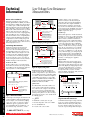
Thermoelectric EMFs
The most common sources of error in low voltage
measurements are thermoelectric voltages (thermoelectric EMFs) generated by temperature differences
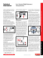
between junctions of conductors (Figure 1).
A
T1
B
T2
A
HI
VAB
LO
Nanovoltmeter
The thermoelectric voltage developed by dissimilar
metals A and B in a circuit is:
LOW LEVEL MEASURE & SOURCE
VAB = QAB ( T1 – T2 )
110
Temperatures of the two
junctions in °C
Seebeck coefficient of
material A with respect
to B, µV/°C
Figure 1. Thermoelectric EMFs
Constructing circuits using the same material for all
conductors minimizes thermoelectric EMF generation. For example, connections made by crimping
copper sleeves or lugs on copper wires results in
cold-welded copper-to-copper junctions, which
generate minimal thermoelectric EMFs. Also, connections must be kept clean and free of oxides.
Low Voltage/Low Resistance
Measurements
HI
Experiment
(source)
VS
Nanovoltmeter
VIN
R
LO
I
Ground 1
Ground 2
Ground bus
VG
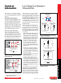
Input voltage to the nanovoltmeter is:
VIN = VS + I R
Resistance of input LO connection
(typically around 100mW)
Current passing through input LO
connection due to ground
voltages (VG) in the ground bus
(magnitude may be amperes).
Source voltage (desired signal)
I R may exceed VS by orders of magnitude.
Figure 2a. Multiple grounds (ground loops)
HI
Experiment
(source)
VS
R
VIN
Nanovoltmeter
LO
I
ZCM
Single
System
Ground
Ground bus
VG
Input voltage to the nanovoltmeter is:
VIN = VS + I R
Current passing through ZCM (MW or
GW) due to VG and currents in the
source (magnitude is typically nA’s).
VIN ≈ VS, since I R is now insignificant compared to VS.
Figure 2b. Single system ground
Minimizing temperature gradients within the
circuit also reduces thermoelectric EMFs. A way to
minimize such gradients is to place all junctions in
close proximity and provide good thermal coupling
to a common, massive heat sink. If this is impractical, thermally couple each pair of corresponding
junctions of dissimilar materials to minimize their
temperature differentials which will also help
minimize the thermoelectric EMFs.
Johnson Noise
The ultimate limit to how well the voltmeter can
resolve a voltage is defined by Johnson (thermal)
noise. This noise is the voltage associated with the
motion of electrons due to their thermal energy.
All sources of voltage will have internal resistance
and thus produce Johnson noise. The noise voltage
developed by any resistance can be calculated from
the following equation:
From this equation, it can be observed that
Johnson noise may be reduced by lowering the
temperature and by decreasing the bandwidth of
the measurement. Decreasing the bandwidth of
the measurement is equivalent to increasing the
response time of the instrument; thus, in addition
to increasing filtering, the bandwidth can be reduced
by increasing instrument integration (typically in
multiples of power line cycles).
Ground Loops
When both the signal source and the measurement
instrument are connected to a common ground bus,
a ground loop is created (Figure 2a). This is the case
when, for instance, a number of instruments are
plugged into power strips on different instrument
racks. Frequently, there is a difference in potential
between the ground points. This potential difference—even though it may be small—can cause large
currents to circulate and create unexpected voltage
drops. The cure for ground loops is to ground the
entire measurement circuit at only one point. The
easiest way to accomplish this is to isolate the DUT
(source) and find a single, good earth-ground point
for the measuring system, as shown in Figure 2b.
Avoid grounding sensitive measurement circuits to
the same ground system used by other instruments,
machinery, or other high power equipment.
Magnetic Fields
Magnetic fields generate spurious voltages in two
circumstances: 1) if the field is changing with time,
and 2) if there is relative motion between the circuit
and the field (Figure 3a). Changing magnetic fields
can be generated from the motion of a conductor
in a magnetic field, from local AC currents caused
by components in the test system, or from the
deliberate ramping of the magnetic field, such as for
magnetoresistance measurements.
a.
Area A (enclosed)
DUT
Voltmeter
B
The voltage developed due to a field passing
through a circuit enclosing a prescribed area is:
VB =
dφ
d (BA)
dA
dB
=
= B
+ A
dt
dt
dt
dt
b.
DUT
Voltmeter
V = 4kTBR
Figure 3. Minimizing interference from
magnetic fields with twisted leads
k = Boltzmann’s constant (1.38 × 10 –23 J/K)
T = absolute temperature of the source in Kelvin
B = noise bandwidth in Hz
R = resistance of the source in ohms
To minimize induced magnetic voltages, leads must
be run close together and should be tied down to
minimize movement. Twisted pair cabling reduces
the effects of magnetic fields in two ways: first, it
reduces the loop area through which the magnetic
1.888.KEITHLEY (U.S. only)
www.keithley.com
A Greater Measure of Confidence
Low Voltage/Low Resistance
Measurements
field is interfering; second, a magnetic field will
create voltages of opposite polarities for neighboring
loops of the twisted pair that will cancel each other.
(Figure 3b)
and the voltage drop across the leads. Typical lead
resistances lie in the range of 1mW to 100mW.
Therefore, the four-wire (Kelvin) connection method
shown in Figure 4b is preferred for low resistance
measurements. In this configuration, the test current
is forced through the DUT through one set of test
leads while the voltage is measured using a second
set of leads called the sense leads. There is very little
current running through the sense leads, so the
sense lead resistance has effectively been eliminated.
Lead Resistance and Four-Wire Method
Resistance measurements in the normal range
(>10W) are generally made using the two-wire
method shown in Figure 4a. The main problem with
the two-wire method for low resistance measurements (<10W) is the error caused by lead resistance.
The voltage measured by the meter will be the sum
of the voltage directly across the test resistance
DMM
Lead
VM Resistances VR
VM
I
Test Current (I)
RLEAD
HI
RS
Resistance
Under Test
RLEAD
LO
Measured = VM
Resistance
I
= RS + (2 × RLEAD)
= RS
Figure 4a. Two-wire resistance measurement:
Lead resistance error
DMM or Micro-ohmmeter
RLEAD
Sense HI
I
VM
Test Current (I)
RLEAD
Sense Current
(pA)
Lead
VM Resistances
Sense LO
RLEAD
Source LO
RLEAD
VR
RS
Resistance
Under Test
Because sense current is negligible, VM = VR
and measured resistance =
• Offset Compensation Technique (Figure 5a)
applies a source current to the resistance being
measured only for part of the measurement
cycle. When the source current is on, the total
voltage measured by the instrument is the sum
of the voltage due to the test current and any
thermoelectric EMFs present in the circuit.
During the second half of the measurement
cycle, the source current is turned off and
the only voltage measured is that due to the
thermoelectric EMF. This unwanted offset
voltage can now be subtracted from the voltage
measurement made during the first half of the
delta mode cycle.
• With the Offset Compensation technique, the
source current is decided by the instrument.
To characterize at a specific current or a variety
of currents, the Current Reversal technique/
Two-step Delta technique (described below) will
provide more flexibility.
VM = Voltage measured by meter
VR = Voltage across resistor
Source HI
Thermoelectric EMFs
Thermoelectric voltages can seriously affect low
resistance measurement accuracy. Given that resistance measurements involve controlling the current
through the DUT, there are ways to overcome these
unwanted offsets in addition to those mentioned in
the low v oltage measurement section, namely, the
offset-compensated ohms method and the currentreversal method.
VM
V
= R = RS
I
I
Figure 4b. Four-wire resistance measurement
• Current Reversal Technique/Two-Step Delta
Technique (Figure 5b)
• Thermoelectric EMFs can also be cancelled
by taking two voltages with test currents of
opposite polarity. The voltage due to the test
current can now be calculated using the formula
shown in Figure 5b. This method provides 2×
better signal-to-noise ratio and, therefore, better
accuracy than the offset compensation technique.
(This is the method employed by the Model
2182A Nanovoltmeter/Model 622x Current Source
combination.)
For these methods to be effective, the consecutive
measurements need to be made rapidly when
compared with the thermal time constant of the
circuit under test. If the instruments’ response
speed is too low, changes in the circuit temperature
during the measurement cycle will cause changes
in the thermoelectric EMFs, with the result that the
thermoelectric EMFs are no longer fully cancelled.
One
measurement
cycle
On
Source
Current
Off
Thermal offset measurement
b. Voltage measurement
with source current on
c. Voltage measurement
with source current off
VEMF
VEMF
VM1
IS
VM2
RS
RS
VM1 = VEMF + IS RS
VM2 = VEMF
VM = (VM1– VM2) = IS RS
Figure 5a. Subtracting thermoelectric EMFs
with Offset Compensation
a. Measurement with Positive Polarity
VEMF
IS
VM+
RS
VM+ = VEMF + IS RS
b. Measurement with Negative Polarity
VEMF
IS
VM–
RS
VM– = VEMF – IS RS
VM =
VM+ – VM–
2
= IS RS
Figure 5b. Canceling thermoelectric EMFs
with Current Reversal
1.888.KEITHLEY (U.S. only)
www.keithley.com
A Greater Measure of Confidence
LOW LEVEL MEASURE & SOURCE
Low Resistance Measurements
Low resistances (<10W) are typically best measured
by sourcing current and measuring voltage. For
very low resistances (micro-ohms or less) or where
there are power limitations involved, this method
will require measuring very low voltages, often
using a nanovoltmeter. Therefore, all the low voltage
techniques and error sources described previously
also apply here. Low resistance measurements are
subject to additional error sources. The next sections
describe methods to minimize some of these.
a. offset compensation
measurement cycle
Technical information: Low voltage/low resistance measurement products
Technical
Information
111
Technical information: Low resistance measurements on the nanoscale
Technical
Information
Resistance Measurements
on the Nanoscale
Three-Step Delta Technique
The three-step delta technique eliminates
errors due to changing thermoelectric voltages
(offsets and drifts) and significantly reduces
white noise. This results in more accurate low
resistance measurements (or more accurate
resistance measurements of any type when it
is necessary to apply very low power to DUTs
that have limited power handling capability).
This technique offers three advantages
over the two-step delta technique.
A delta reading is a pair of voltage measurements
made at a positive test current and a negative test
current. Both the two-step and three-step delta
techniques can cancel constant thermoelectric
voltage by alternating the test current. The
three-step technique can also cancel changing
thermoelectric voltages by alternating the
current source three times to make two delta
measurements: one at a negative-going step and
one at a positive going step. This eliminates errors
caused by changing thermoelectric EMFs 10×
better than the two-step technique (Figure 6).
The three-step technique provides accurate voltage readings of the intended signal unimpeded
by thermoelectric offsets and drifts only if the
current source alternates quickly and the volt
meter makes accurate voltage measurements
within a short time interval. The Model 622x
Current Source paired with the Model 2182A
Nanovoltmeter is optimized for this application. These products implement the three-step
technique in a way that offers better white noise
immunity than the two-step technique by spending over 90% of its time performing measurements. In addition, the three-step technique is
faster, providing 47 readings/second to support
a wider variety of applications. Interestingly,
the formula used for the three-step technique
is identical to that used for d ifferential conductance (Figure 10).
Pulsed, Low Voltage Measurements
Short test pulses are becoming increasingly
important as modern electronics continue to
shrink in size. Short pulses mean less power put
into the DUT. In very small devices, sometimes
even a small amount of power is enough to
destroy them. In other devices, a small amount
of power could raise the temperature significantly, causing the measurements to be invalid.
With superconducting devices, a small amount
of heat introduced while making measurements
can raise the device temperature and alter the
results. When sourcing current and measuring
voltage, the sourced current dissipates heat
(I2R) into the device and leads. With the lowest
resistance devices (<10µW), the power dissipated during the measurement may be primarily
at contact points, etc., rather than in the device
itself. It is important to complete the measurement before this heat can be conducted to the
device itself, so fast pulsed measurements are
critical even at these lowest resistances.
160.00
2pt Delta Resistance
3pt Delta Resistance
140.00
Sourced
I
With higher resistance devices, significant power
is dissipated within the device. Therefore, with
these devices, it is even more important to
reduce the measurement power by reducing the
source current or the source pulse width. Many
tests measure device properties across a range of
currents, so reducing the current is not usually
an option. Shorter pulses are the only solution.
The Model 6221 Current Source was designed
with microsecond rise times on all ranges
to enable short pulses. The Model 2182A
Nanovoltmeter offers a low latency trigger, so
that a measurement can begin as little as 10µs
after the Model 6221 pulse has been applied.
The entire pulse, including a complete nanovolt
measurement, can be as short as 50µs. In addition, all pulsed measurements of the 6221/2182A
are line synchronized. This line synchronization, combined with the three-step delta technique, causes all 50/60Hz noise to be rejected
(Figure 7).
Dry Circuit Testing
Applications that involve measuring contact
resistance may require that existing oxide layers
remain unbroken during the measurement. This
can be done by limiting the test current to less
than 100mA and the voltage drop across the
sample to no more than 20mV. Most low resistance meters have this “dry circuit” measurement
technique built in.
1ms
0.6µA
112
resistance (W)
LOW LEVEL MEASURE & SOURCE
120.00
100.00
Time
80.00
Measured
V
60.00
60Hz (50Hz) line
frequency noise
(e.g. 0.4mV rms)
40.00
20.00
DCV offset level
(e.g. 0.5mV)
0.00
Time
Figure 6. 1000 delta resistance readings using 100W resistor and 10nA
source current.
Figure 7. Operating at low voltage levels, measurements are susceptible to line frequency interference. Using line synchronization eliminates line frequency noise.
1.888.KEITHLEY (U.S. only)
www.keithley.com
A Greater Measure of Confidence
Technical
Information
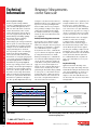
In the macroscopic world, conductors may
have obeyed Ohm’s Law (Figure 8a), but in the
nanoscale, Ohm’s definition of resistance is no
longer relevant (Figure 8b). Because the slope
of the I-V curve is no longer a fundamental constant of the material, a detailed measurement of
the slope of that I-V curve at every point is needed to study nanodevices. This plot of differential
conductance (dG = dI/dV) is the most important
measurement made on small scale devices, but
presents a unique set of challenges.
I
I
V
Figure 8a.
Macroscopic scale
(Classical)
V
Figure 8b. Nanoscale
(Quantum)
Differential conductance measurements are performed in many areas of research, though sometimes under different names, such as: electron
energy spectroscopy, tunneling spectroscopy,
and density of states. The fundamental reason
that differential conductance is interesting is that
the conductance reaches a maximum at voltages (or more precisely, at electron energies in
eV) at which the electrons are most active. This
explains why dI/dV is directly proportional to
the density of states and is the most direct way
to measure it.
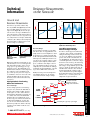
2
300
1
200
I (µA) 0
dI/dV 100
(µs)
–1
0
–2
–0.01
–0.005
0
0.01
–100
–0.01
–0.005
V
0
0.005
0.01
V
Figure 9a. I-V curve
Figure 9b. Differentiated I-V curve. True
dI/dV curve obscured by noise.
The AC Technique:
Four-Wire, Source Current –
Measure Voltage Technique
Now there is another approach to differential
conductance. This technique is performed by
adding an alternating current to a linear staircase sweep. The amplitude of the alternating
portion of the current is the differential current, dI (Figure 10). The differential current is
constant throughout the test. After the voltage is
measured at each current step, the delta voltage
between consecutive steps is calculated. Each
delta voltage is averaged with the previous delta
voltage to calculate the differential voltage, dV.
The differential conductance, dG, can now be
derived using dI/dV. This technique requires
only one measurement sweep when using the
Model 2182A Nanovoltmeter and a Model 622x
Current Source, so it is faster, quieter, and
simpler than any previous method.
The AC technique superimposes a low amplitude AC sine wave on a stepped DC bias to the
sample. It then uses lock-in amplifiers to obtain
the AC voltage across and AC current through
the DUT. The problem with this method is that
while it provides a small improvement in noise
over the I-V curve technique, it imposes a large
penalty in system complexity, which includes
precise coordination and computer control of
six to eight instruments. Other reasons for the
complexity of the system include the challenges
of mixing the AC signal and DC bias, of ground
loops, and of common mode current noise.
Keithley has developed a new technique that
is both simple and low noise: the four-wire,
Source Current–Measure Voltage technique.
Existing Methods of Performing
Differential Conductance
The I-V Technique:
The I-V technique performs a current-voltage
sweep (I-V curve) and takes the mathematical
derivative. This technique is simple, but noisy.
It only requires one source and one measurement instrument, which makes it relatively easy
to coordinate and control. The fundamental
problem is that even a small amount of noise
becomes a large noise when the measurements
are differentiated (Figure 9). To reduce this
noise, the I-V curve and its derivative must be
measured repeatedly. Noise will be reduced by
√N, where N is the number of times the curve
is measured.
0.005
2182a
V-Meas
622X
I-source
Meas
V1
Meas
V2
Delay
Meas
V3
Meas
V4
dI
Meas
V5 Meas
V6
Each A/D conversion
integrates (averages)
voltage over a fixed time.
dI
4th Cycle
3rd Cycle
2nd Cycle
1st Cycle
1st Reading ∆V = [(V1–V2) + (V3–V2)]/4
Figure 10. Detail of applied current and measured device voltage
1.888.KEITHLEY (U.S. only)
www.keithley.com
A Greater Measure of Confidence
LOW LEVEL MEASURE & SOURCE
Nanovolt Level
Resistance Measurements
Technical information: Low resistance measurements on the nanoscale
Resistance Measurements
on the Nanoscale
113
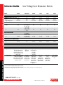
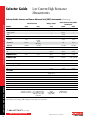
Selector Guide
Selector guide: Low voltage and low resistance instruments
Model
Page
Voltage Range (Full Scale)
10 mV
From
100 V
To
1.2 nV rms
Input Voltage Noise
LOW LEVEL MEASURE & SOURCE
6220/6221
121
3706A
126
2750
264
2010
253
2002
247
N/A
N/A
N/A
100 mV
300 V
100 nV rms
100 mV
1000 V
<1.5 µV rms
100 mV
1000 V
100 nV rms
200 mV
1000 V
150 nV rms
N/A
N/A
N/A
N/A
N/A
N/A
N/A
N/A
0.9 mW
0.4 mW
0.9 mW
1.2 mW
100 MW
100 MW
100 MW
1 GW
–150°C
1820°C
–200°C
1820°C
–200°C
1372°C
–200°C
1820°C
•
•
•
Banana jacks (4)
•
•
•
Banana jacks (4)
•
•
•
Banana jacks (4)
Dry circuit.
Offset
compensation.
DMM. IEEE-488.
RS-232. Digital I/O.
Plug-in modules.
Dry circuit.
Offset
compensation.
DMM. IEEE-488.
RS-232. Plug-in
scanner cards.
8½ digits. DMM.
Plug-in scanner
cards.
CURRENT Range
From
N/A
To
N/A
100 fA DC
(also 2 pA peak
AC, 6221 only)
±105 mA DC
(also 100 mA
peak AC, 6221
only)
Resistance Range
From1
To2
10 nW 3
100 MW 3
Thermocouple Temperature
–200°C
From
1820°C
To
FEATURES
IEEE-488
RS-232
CE
Input Connection
Special Features
114
2182A
115
Low Voltage/Low Resistance Meters
10 nW (when
used with 2182A)
100 MW (when
used with 2182A)
N/A
N/A
•
•
•
•
•
•
•
•
Special low thermoelectric
Trigger Link, Rear panel 15 pin
w/copper pins. Optional
Digital I/O,
D-SUB. Optional
2187-4 Modular Probe Kit
Ethernet
accessories:
adds banana plugs, spring
3706-BAN,
clips, needle probes, and
3706-BKPL,
alligator clips.
3706-TLK
Delta mode and differential
Controls
Dry circuit. Offset
conductance with Model
Model 2182A
compensation.
6220 or 6221. Pulsed I-V with
for low-power
Plug-in switch/
Model 6221. Analog output. resistance and I-V relay modules.
IEEE-488. RS-232.
measurements.
USB. LXI Class
B/Ethernet with
IEEE-1588 protocol.
Digital I/O.
Notes
1. Lowest resistance measurable with better than 10% accuracy.
2.Highest resistance measurable with better than 1% accuracy.
3. Delta mode, offset voltage compensation with external current source. 10nW if used with 5A test current with Model 2440.
1.888.KEITHLEY (U.S. only)
www.keithley.com
A Greater Measure of Confidence
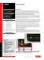
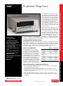
The two-channel Model 2182A Nanovoltmeter
is optimized for making stable, low noise
voltage measurements and for characterizing
low resistance materials and devices reliably
and repeatably. It provides higher measurement
speed and significantly better noise performance
than alternative low voltage measurement
solutions.
The Model 2182A represents the next step
forward in Keithley nanovoltmeter technology,
replacing the original Model 2182 and offering
enhanced capabilities including pulse capability,
lower measurement noise, faster current reversals, and a simplified delta mode for making
resistance measurements in combination with a
reversing current source, such as the Model 6220
or 6221.
• Make low noise measurements at
high speeds, typically just 15nV
p-p noise at 1s response time,
40–50nV p-p noise at 60ms
• Delta mode coordinates
measurements with a reversing
current source at up to 24Hz
with 30nV p-p noise (typical) for
one reading. Averages multiple
readings for greater noise
reduction
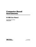
Flexible, Effective Speed/Noise Trade-offs
The Model 2182A makes it easy to choose the best speed/filter combination for a particular application’s response time and noise level requirements. The ability to select from a wide range of response
times allows optimizing speed/noise trade-offs. Low noise levels are assured over a wide range of
useful response times, e.g., 15nV p-p noise at 1s and 40-50nV p-p noise at 60ms are typical. Figure 1
illustrates the Model 2182A’s noise performance.
150
• Synchronization to line provides
110dB NMRR and minimizes
the effect of AC common-mode
currents
• Dual channels support measuring
voltage, temperature, or the ratio
of an unknown resistance to a
reference resistor
• Built-in thermocouple
linearization and cold junction
compensation
100
50
Low noise measurements for research, metrology, and other low voltage testing applications
Nanovoltmeter
Keithley 2182A
nV
nV/µΩ Meter
0
-50
-100
0
Number of Readings
100
Figure 1. Compare the Model 2182A’s DC noise performance with a nanovolt/micro-ohmmeter’s. All the data shown was taken at 10 readings per second with a low thermal short
applied to the input.
1.888.KEITHLEY (U.S. only)
www.keithley.com
A Greater Measure of Confidence
LOW LEVEL MEASURE & SOURCE
2182A
115
Low noise measurements for research, metrology, and other low voltage testing applications
2182A
Ordering Information
2182ANanovoltmeter
Accessories Supplied
2107-4 Low Thermal Input Cable
with spade lugs, 1.2m (4 ft).
User manual, service
manual, contact cleaner,
line cord, alligator clips.
Accessories Available
2107-30
2182-KIT
2187-4
2188
4288-1
4288-2
7007-1
7007-2
7009-5
8501-1
8501-2
8503
KPCI-488LPA
KUSB-488B
Low Thermal Input Cable with spade lugs,
9.1m (30 ft)
Low Thermal Connector with strain relief
Low Thermal Test Lead Kit
Low Thermal Calibration Shorting Plug
Single Fixed Rack Mount Kit
Dual Fixed Rack Mount Kit
Shielded GPIB Cable, 1m (3.2 ft)
Shielded GPIB Cable, 2m (6.5 ft)
Shielded RS-232 Cable, 1.5m (5 ft)
Trigger Link Cable, 1m (3.2 ft)
Trigger Link Cable, 2m (6.5 ft)
Trigger Link Cable to 2 male BNC connectors
IEEE-488 Interface/Controller for the PCI Bus
IEEE-488 USB-to-GPIB Interface Adapter
Services Available
Nanovoltmeter
Reliable Results
Power line noise can compromise measurement accuracy significantly at the nanovolt level. The
Model 2182A reduces this interference by synchronizing its measurement cycle to line, which
minimizes variations due to readings that begin at different phases of the line cycle. The result is
exceptionally high immunity to line interference with little or no shielding and filtering required.
Optimized for Use with Model 6220/6221 Current Sources
Device test and characterization for today’s very small and power-efficient electronics requires sourcing low current levels, which demands the use of a precision, low current source. Lower stimulus
currents produce lower—and harder to measure—voltages across the devices. Linking the Model
2182A Nanovoltmeter with a Model 6220 or 6221 Current Source makes it possible to address both of
these challenges in one easy-to-use configuration.
When connected, the Model 2182A and Model 6220 or 6221 can be operated like a single instrument.
Their simple connections eliminate the isolation and noise current problems that plague other solutions. The Model 2182A/622X combination allows making delta mode and differential conductance
measurements faster and with less noise than the original Model 2182 design allowed. The Model
2182A will also work together with the Model 6221 to make pulse-mode measurements.
The 2182A/622X combination is ideal for a variety of applications, including resistance measurements, pulsed I-V measurements, and differential conductance measurements, providing significant
advantages over earlier solutions like lock-in amplifiers or AC resistance bridges. The 2182A/622X
combination is also well suited for many nanotechnology applications because it can measure
resistance without dissipating much power into the device under test (DUT), which would otherwise
invalidate results or even destroy the DUT.
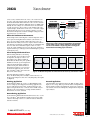
An Easy-to-Use Delta Mode
Keithley originally created the delta mode method for measuring voltage and resistance for the
Model 2182 and a triggerable external current source, such as the Model 2400 SourceMeter® SMU
instrument. Basically, the delta mode automatically triggers the current source to alternate the signal
polarity, and then triggers a nanovoltmeter reading at each polarity. This current reversal technique
2182A-3Y-EW
1-year factory warranty extended to 3 years
from date of shipment
C/2182A-3Y-ISO 3 (ISO-17025 accredited) calibrations within 3
years of purchase*
* Not available in all countries
5nV
LOW LEVEL MEASURE & SOURCE
Applications
116
Research
• Determining the transition
temperature of superconductive
materials
• I-V characterization of a material
at a specific temperature
• Calorimetry
• Differential thermometry
• Superconductivity
• Nanomaterials
Metrology
• Intercomparisons of standard cells
• Null meter for resistance bridge
measurements
4µV
DC
Measurement
Delta Mode
Measurement
Figure 2. Results from a Model 2182A/6220 using the delta mode to measure a 10mW resistor
with a 20µA test current. The free Model 6220/6221 instrument control example start-up
software used here can be downloaded from www.keithley.com.
1.888.KEITHLEY (U.S. only)
www.keithley.com
A Greater Measure of Confidence
cancels out any constant thermoelectric offsets, so the results reflect the
true value of the voltage being measured. The improved delta mode for
the Model 2182A and the Model 622X current sources uses the same basic
technique, but the way in which it’s implemented has been simplified dramatically. The new technique can cancel thermoelectric offsets that drift
over time (not just static offsets), produces results in half the time of the
original technique, and allows the current source to control and configure
the Model 2182A. Two key presses are all that’s required to set up the
measurement. The improved cancellation and higher reading rates reduce
measurement noise to as little as 1nV.
Differential Conductance Measurements
Characterizing non-linear tunneling devices and low temperature devices
often requires measuring differential conductance (the derivative of a
device’s I-V curve). When used with a Model 622X current source, the
Model 2182A is the industry’s fastest, most complete solution for differential conductance measurements, providing 10X the speed and significantly
lower noise than other instrumentation options. There’s no need to
average the results of multiple sweeps, because data can be obtained in a
single measurement pass, reducing test time and minimizing the potential
for measurement error.
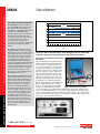
Pulsed Testing with the Model 6221
When measuring small devices, introducing
even tiny amounts of heat to the DUT can raise
its temperature, skewing test results or even
destroying the device. When used with the
Model 2182A, the Model 6221’s pulse capability
minimizes the amount of power dissipated into
a DUT. The Model 2182A/6221 combination
synchronizes the pulse and measurement. A
measurement can begin as soon as 16µs after
the Model 6221 applies the pulse. The entire
pulse, including a complete nanovolt measurement, can be as short as 50µs.
Competition
100µs
Model 2182A
2182A NANOVOLTMETER
Model 622X
RS-232
Trigger Link
GPIB or
Ethernet
6220 DC AND AC CURRENT SOURCE
DUT
Figure 3. It’s simple to connect the Model 2182A to the Model
6220 or 6221 to make a variety of measurements. The instrument
control example start-up software available for the Model 622X
current sources includes a step-by-step guide to setting up the
instrumentation and making proper connections.
2182A
2182A in delta mode
0.5µA
Figure 4. The Model 2182A produces the lowest transient currents of any nanovoltmeter available.
In the delta, differential conductance, and pulse
modes, The Model 2182A produces virtually no transient currents, so it’s
ideal for characterizing devices that can be easily disrupted by current spikes
(see Figure 4).
Metrology Applications
The Model 2182A combines the accuracy of a digital multimeter with
low noise at high speeds for high-precision metrology applications. Its
low noise, high signal observation time, fast measurement rates, and
2ppm accuracy provide the most cost-effective meter available today for
applications such as intercomparison of voltage standards and direct
measurements of resistance standards.
Research Applications
The Model 2182A’s 1nV sensitivity, thermoelectric EMF cancellation, direct
display of “true” voltage, ability to perform calculations, and high measurement speed makes it ideal for determining the characteristics of materials
such as metals, low resistance filled plastics, and high and low temperature
superconductors.
Nanotechnology Applications
The Model 2182A combined with the Model 622X current source or Series
2400 SourceMeter® SMU instrument is a highly accurate and repeatable
solution for measuring resistances on carbon nanotube based materials
and silicon nanowires.
1.888.KEITHLEY (U.S. only)
www.keithley.com
A Greater Measure of Confidence
Low noise measurements for research, metrology, and other low voltage testing applications
Nanovoltmeter
LOW LEVEL MEASURE & SOURCE
2182A
117
LOW LEVEL MEASURE & SOURCE
Low noise measurements for research, metrology, and other low voltage testing applications
2182A
118
Nanovoltmeter
Three Ways to Measure Nanovolts
220
DC nanovoltmeters. DC nanovoltmeters
and sensitive DMMs both provide low noise
DC voltage measurements by using long
integration times and highly filtered readings
to minimize the bandwidth near DC.
Unfortunately, this approach has limitations,
particularly the fact that thermal voltages
develop in the sample and connections vary,
so long integration times don’t improve
measurement precision. With a noise
specification of just 6nV p-p, the Model 2182A
is the lowest noise digital nanovoltmeter
available.
215
AC technique. The limitations of the long
integration and filtered readings technique
have led many people to use an AC technique
for measuring low resistances and voltages.
In this method, an AC excitation is applied
to the sample and the voltage is detected
synchronously at the same frequency and
an optimum phase. While this technique
removes the varying DC component, in many
experiments at high frequencies, users can
experience problems related to phase shifts
caused by spurious capacitance or the L/R
time constant. At low frequencies, as the
AC frequency is reduced to minimize phase
shifts, amplifier noise increases.
The current reversal method. The Model
2182A is optimized for the current reversal
method, which combines the advantages of
both earlier approaches. In this technique,
the DC test current is reversed, then the
difference in voltage due to the difference
in current is determined. Typically, this
measurement is performed at a few hertz (a
frequency just high enough for the current
to be reversed before the thermal voltages
can change). The Model 2182A’s low noise
performance at measurement times of a
few hundred milliseconds to a few seconds
means that the reversal period can be set
quite small in comparison with the thermal
time constant of the sample and the con
nections, effectively reducing the impact of
thermal voltages.
30
Temperature
(°C)
25
210
20
205
15
200
Voltage
(nV)
195
10
5
190
0
185
–5
180
0
8
17
–10
25 33 42 50 58 67 75 83 92 100 108 117 125
Minutes
Figure 5. The Model 2182A’s delta mode provides extremely stable results, even in the presence of large ambient temperature changes. In this challenging example, the 200nV signal
results from a 20µA current sourced by a Model 6221 through a 10mW test resistor.
Optional Accessory: Model 2187-4 Low Thermal
Test Lead Kit
The standard cabling provided with the Model
2182A Nanovoltmeter and Model 622X Current
Sources provides everything normally needed
to connect the instruments to each other and to
the DUT. The Model 2187-4 Low Thermal Test
Lead Kit is required when the cabling provided
may not be sufficient for specific applications,
such as when the DUT has special connection
requirements. The kit includes an input cable
with banana terminations, banana extensions,
sprung-hook clips, alligator clips, needle probes,
and spade lugs to accommodate virtually any
DUT. The Model 2187-4 is also helpful when the
DUT has roughly 1GW impedance or higher.
In this case, measuring with the Model 2182A
Figure 6. Model 2187-4 Test Lead Kit
directly across the DUT will lead to loading
errors. The Model 2187-4 Low Thermal Test Lead Kit provides a banana cable and banana jack
extender to allow the Model 2182A to connect easily to the Model 622X’s low impedance guard
output, so the Model 2182A can measure the DUT voltage indirectly. This same configuration also
removes the Model 2182A’s input capacitance from the DUT, so it improves device response time,
which may be critical for pulsed measurements.
Figure 7. Model 2182A rear panel
1.888.KEITHLEY (U.S. only)
www.keithley.com
A Greater Measure of Confidence
2182A
Nanovoltmeter
Volts Specifications (20% over range)
Conditions: 1PLC with 10 reading digital filter or 5PLC with 2 reading digital filter.
Accuracy: ±(ppm of reading + ppm of range)
(ppm = parts per million) (e.g., 10ppm = 0.001%)Temperature
Channel 1
Input
24 Hour 1
90 Day
1 Year
2 Year
Coefficient
RangeResolutionResistance
TCAL ±1°C
TCAL ±5°C
TCAL ±5°C
TCAL ±5°C
0°–18°C & 28°–50°C
10.000000mV 2, 3, 4
1 nV
>10GW
20 + 4
40 + 4
50 + 4
60 + 4
(1 + 0.5)/°C
100.00000 mV
10 nV
>10GW
10 + 3
25 + 3
30 + 4
40 + 5
(1 + 0.2)/°C
1.0000000 V
100 nV
>10 GW
7 + 2
18 + 2
25 + 2
32 + 3
(1 + 0.1)/°C
10.000000 V
1 µV
>10GW
2 + 1 5
18 + 2
25 + 2
32 + 3
(1 + 0.1)/°C
100.00000V 4
10 µV
10 MW ±1%
10 + 3
25 + 3
35 + 4
52 + 5
(1 + 0.5)/°C
>10GW
>10 G
W
>10 G
W
10 + 6
7 + 2
2 + 1 5
25 + 6
18 + 2
18 + 2
30 + 7
25 + 2
25 + 2
40 + 7
32 + 3
32 + 3
(1 + 1 )/°C
(1 + 0.5)/°C
(1 + 0.5)/°C
CHANNEL 1/CHANNEL 2 RATIO: For input signals ≥1% of the range, Ratio Accuracy =
±{[Channel 1 ppm of Reading + Channel 1 ppm of Range * (Channel 1 Range/Channel 1 Input)] + [Channel 2 ppm of Reading + Channel 2 ppm of Range * (Channel 2 Range/Channel 2 Input)]}.
DELTA (hardware-triggered coordination with Series 24XX, Series 26XXA, or Series 622X current sources for low noise R measurement):
Accuracy = accuracy of selected Channel 1 range plus accuracy of I source range.
DELTA measurement noise with 6220 or 6221: Typical 3nVrms / Hz (10mV range)21. 1Hz achieved with 1PLC, delay = 1ms, RPT filter = 23 (20 if 50Hz).
PULSE-MODE (with 6221): Line synchronized voltage measurements within current pulses from 50µs to 12ms, pulse repetition rate up to 12Hz.
Pulse measurement noise (typical rms noise, R DUT<10W): ±(0.009ppm of range*) / meas_time / pulse_avg_count + 3nV** / (2 · meas_time · pulse_avg_count) for 10mV range.
* 0.0028ppm for the 100mV range, 0.0016ppm for ranges 1V and above.
**8nV/ Hz for ranges above 10mV. meas_time (seconds) = pulsewidth – pulse_meas_delay in 33µs incr.
DC Noise Performance 7 (DC noise expressed in volts peak-to-peak)
Response time = time required for reading to be settled within noise levels from a stepped input, 60Hz operation.
Channel 1
ResponseRange
Time
NPLC, Filter
10 mV
100 mV
1 V
10 V
25.0 s
5, 75
6 nV
20 nV
75 nV
750 nV
4.0 s
5, 10
15 nV
50 nV
150 nV
1.5 µV
1.0 s
1, 18
25 nV
175 nV
600 nV
2.5 µV
667 ms
1, 10 or 5, 2
35 nV
250 nV
650 nV
3.3 µV
60 ms
1, Off
70 nV
300 nV
700 nV
6.6 µV
Channel 2 6, 10
25.0 s
4.0 s
1.0 s
85 ms
5, 75
5, 10
1, 10 or 5, 2
1, Off
—
—
—
—
150 nV
150 nV
175 nV
425 nV
200 nV
200 nV
400 nV
1 µV
Voltage Noise vs. Source Resistance 11
(DC noise expressed in volts peak-to-peak)
SourceAnalogDigital
Resistance NoiseFilterFilter
0
W
6 nV
Off
100
100
W
8 nV
Off
100
1kW
15 nV
Off
100
10kW
35 nV
Off
100
100kW
100 nV
On
100
1MW
350 nV
On
100
Temperature (Thermocouples) 12
Accuracy
(Displayed in °C, °F, or K. Accuracy based on
90 Day/1 Year
ITS-90, exclusive of thermocouple errors.)
23° ±5°C
Relative to Simulated
TypeRangeResolutionReference Junction
J
–200 to +760°C
0.001 °C
±0.2 °C
K
–200 to +1372°C
0.001 °C
±0.2 °C
N
–200 to+1300°C
0.001 °C
±0.2 °C
T
–200 to +400°C
0.001 °C
±0.2 °C
E
–200 to+1000°C
0.001 °C
±0.2 °C
R
0 to +1768°C
0.1 °C
±0.2 °C
S
0 to +1768°C
0.1 °C
±0.2 °C
B
+350 to +1820°C
0.1 °C
±0.2 °C
750 nV
1.5 µV
2.5 µV
9.5 µV
100 V
75 µV
75 µV
100 µV
150 µV
300 µV
—
—
—
—
Model 2182A specifications
10 nV
100 nV
1 µV
NMRR 8CMRR 9
110 dB
140 dB
100 dB
140 dB
95 dB
140 dB
90 dB
140 dB
60 dB
140 dB
110 dB
100 dB
90 dB
60 dB
140 dB
140 dB
140 dB
140 dB
Operating Characteristics 13, 14
60Hz (50Hz) Operation
Function
DigitsReadings/s
PLCs
DCV Channel 1,
7.5
3(2)
5
Channel 2,7.5 17, 19
6(4)
5
Thermocouple6.5 18, 19
18(15)
1
6.5 18, 19, 20
45(36)
1
5.5 17, 19
80(72)
0.1
4.5 16, 17, 19
115(105)
0.01
Channel 1/Channel 2 (Ratio),
7.5
1.5(1.3)
5
Delta with 24XX, Scan7.5 17, 19
2.3(2.1)
5
6.5 18
8.5(7.5)
1
6.5 18, 20
20 (16)
1
5.5 17
30 (29)
0.1
4.5 17
41(40)
0.01
Delta with 622X
6.5
47(40.0) 221
System Speeds 13, 15
Range Change Time: 14
<40 ms (<50 ms).
Function Change Time: 14
<45 ms (<55 ms).
Autorange Time: 14
<60 ms (<70 ms).
ASCII Reading to RS-232 (19.2K Baud):40/s (40/s).
Max. Internal Trigger Rate: 16
120/s(120/s).
Max. External Trigger Rate: 16
120/s(120/s).
1.888.KEITHLEY (U.S. only)
www.keithley.com
A Greater Measure of Confidence
LOW LEVEL MEASURE & SOURCE
Channel 2 6, 10
100.00000 mV
1.0000000 V
10.000000 V
119
2182A
Nanovoltmeter
Model 2182A specifications
Measurement Characteristics
A/D Linearity: ±(0.8ppm of reading + 0.5ppm of range).
Front Autozero Off Error
10mV–10V:
Add ±(8ppm of range + 500µV) for <10 minutes and ±1°C.
NOTE: Offset voltage error does not apply for Delta Mode.
Autozero Off Error
10mV:
Add ±(8ppm of range + 100nV) for <10 minutes and ±1°C.
100mV–100V: Add ±(8ppm of range + 10µV) for <10 minutes and ±1°C.
NOTE: Offset voltage error does not apply for Delta Mode.
Input Impedance
10mV–10V:>10GW, in parallel with <1.5nF (Front Filter ON).
10mV–10V:>10GW, in parallel with <0.5nF (Front Filter OFF).
100V:10MW ±1%.
DC Input Bias Current: <60pA DC at 23°C, –10V to 5V. <120pA @ 23°C, 5V to 10V.
Common Mode Current: <50nA p-p at 50Hz or 60Hz.
Input Protection: 150V peak to any terminal. 70V peak Channel 1 LO to Channel 2 LO.
Channel Isolation: >10GW.
Earth Isolation: 350V peak, >10GW and <150pF any terminal to earth. Add 35pF/ft with
Model 2107 Low Thermal Input Cable.
Analog Output
Maximum Output: ±1.2V.
Accuracy: ±(0.1% of output + 1mV).
Output Resistance: 1kW ±5%.
Gain: Adjustable from 10 –9 to 106. With gain set to 1, a full range input will produce a 1V output.
Output REL: Selects the value of input that represents 0V at output. The reference value can be
either programmed value or the value of the previous input.
Triggering and Memory
Window Filter Sensitivity: 0.01%, 0.1%, 1%, 10%, or full scale of range (none).
Reading Hold Sensitivity: 0.01%, 0.1%, 1%, or 10% of reading.
Trigger Delay: 0 to 99 hours (1ms step size).
External Trigger Delay: 2ms + <1ms jitter with auto zero off, trigger delay = 0.
Memory Size: 1024 readings.
Math Functions
Rel, Min/Max/Average/Std Dev/Peak-to-Peak (of stored reading), Limit Test, %, and mX+b with userdefined units displayed.
Remote Interface
LOW LEVEL MEASURE & SOURCE
Keithley 182 emulation.
GPIB (IEEE-488.2) and RS-232C.
SCPI (Standard Commands for Programmable Instruments).
120
General
Power Supply: 100V/120V/220V/240V.
Line Frequency: 50Hz, 60Hz, and 400Hz, automatically sensed at power-up.
Power Consumption: 22VA.
Magnetic Field Density: 10mV range 4.0s response noise tested to 500 gauss.
Operating Environment: Specified for 0° to 50°C. Specified to 80% RH at 35°C.
Storage Environment: –40° to 70°C.
EMC: Complies with European Union Directive 89/336/EEC (CE marking requirement), FCC
part 15 class B, CISPR 11, IEC 801-2, IEC-801-3, IEC 801-4.
Safety: Complies with European Union Directive 73/23/EEC (low voltage directive); meets
EN61010-1 safety standard. Installation category I.
Vibration: MIL-T-28800E Type III, Class 5.
Warm-Up: 2.5 hours to rated accuracy.
Dimensions: Rack Mounting: 89mm high × 213mm wide × 370mm deep (3.5 in × 8.375
in × 14.563 in). Bench Configuration (with handles and feet): 104mm high × 238mm
wide × 370mm deep (4.125 in × 9.375 in ×14.563 in).
Shipping Weight: 5kg (11 lbs).
Notes
1. Relative to calibration accuracy.
2. With Analog Filter on, add 20ppm of reading to listed specification.
3. When properly zeroed using REL function. If REL is not used, add 100nV to the range accuracy.
4. Specifications include the use of ACAL function. If ACAL is not used, add 9ppm of reading/°C
from Tcal to the listed specification. Tcal is the internal temperature stored during ACAL.
5. For 5PLC with 2-reading Digital Filter. Use ±(4ppm of reading + 2ppm of range) for 1PLC with
10-reading Digital Filter.
6. Channel 2 must be referenced to Channel 1. Channel 2 HI must not exceed 125% (referenced
to Channel 1 LO) of Channel 2 range selected.
7. Noise behavior using 2188 Low Thermal Short after 2.5 hour warm-up. ±1°C. Analog Filter off.
Observation time = 10× response time or 2 minutes, whichever is less.
8. For Lsync On, line frequency ±0.1%. If Lsync Off, use 60dB.
9. For 1kW unbalance in LO lead. AC CMRR is 70dB.
10. For Low Q mode On, add the following to DC noise and range accuracy at stated response
time: 200nV p-p @ 25s, 500nV p-p @ 4.0s, 1.2µV p-p @ 1s, and 5µV p-p @ 85ms.
11.A fter 2.5 hour warm-up, ±1°C, 5PLC, 2 minute observation time, Channel 1 10mV range only.
12.For Channel 1 or Channel 2, add 0.3°C for external reference junction. Add 2°C for internal
reference junction.
13.Speeds are for 60Hz (50Hz) operation using factory defaults operating conditions (*RST).
Autorange Off, Display Off, Trigger Delay = 0, Analog Output off.
14.Speeds include measurements and binary data transfer out the GPIB. Analog Filter On, 4
readings/s max.
15.Auto Zero Off, NPLC = 0.01.
16. 10mV range, 80 readings/s max.
17. Sample count = 1024, Auto Zero Off.
18.For Lsync On, reduce reading rate by 15%.
19. For Channel 2 Low Q mode Off, reduce reading rate by 30%.
20.Front Auto Zero off, Auto Zero off.
21. Applies to measurements of room temperature resistances <10W, Isource range ≤20µA.
22.Display off, delay 1ms.
1.888.KEITHLEY (U.S. only)
www.keithley.com
A Greater Measure of Confidence
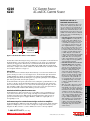
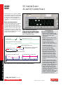
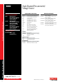
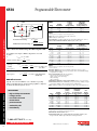
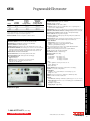
6220
6221
DC Current Source
AC and DC Current Source
6220 and 6221
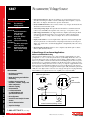
• Source and sink (programmable
load) 100fA to 100mA
• Built-in RS-232, GPIB, Trigger
Link, and digital I/O interfaces
• Reconfigurable triax output
simplifies matching the
application’s guarding
requirements
• Model 220 emulation mode
eliminates need to reprogram
existing applications
6221 Only
• Source AC currents from 4pA
to 210mA peak to peak for AC
characterization of components
and materials. The 6221’s
10MHz output update rate
generates smooth sine waves
up to 100kHz
• Built-in standard and arbitrary
waveform generators with
1mHz to 100kHz frequency
range. Applications include use
as a complex programmable
load or sensor signal and for
noise emulation
• Programmable pulse widths
as short as 5µs, limiting power
dissipation in delicate com
ponents. Supports pulsed I-V
measurements down to 50µs
when used with Model 2182A
Nanovoltmeter
• Built-in Ethernet interface for
easy remote control without a
GPIB controller card
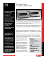
The Model 6220 DC Current Source and Model 6221 AC and DC Current Source combine ease of use
with exceptionally low current noise. Low current sourcing is critical to applications in test environments ranging from R&D to production, especially in the semiconductor, nanotechnology, and superconductor industries. High sourcing accuracy and built-in control functions make the Models 6220
and 6221 ideal for applications like Hall measurements, resistance measurements using delta mode,
pulsed measurements, and differential conductance measurements.
The need for precision, low current sourcing. Device testing and characterization for today’s very
small and power-efficient electronics requires sourcing low current levels, which demands the use of
a precision, low current source. Lower stimulus currents produce lower—and harder to measure—
voltages across the device. Combining the Model 6220 or 6221 with a Model 2182A Nanovoltmeter
makes it possible to address both of these challenges.
AC current source and current source waveform generator. The Model 6221 is the only low
current AC source on the market. Before its introduction, researchers and engineers were forced to
build their own AC current sources. This cost-effective source provides better accuracy, consistency,
reliability, and robustness than “home-made” solutions. The Model 6221 is also the only commercially
available current source waveform generator, which greatly simplifies creating and outputting complex waveforms.
Simple programming. Both current sources are fully programmable via the front panel controls or
from an external controller via RS-232 or GPIB interfaces; the Model 6221 also features an Ethernet
interface for remote control from anywhere there’s an Ethernet connection. Both instruments can
source DC currents from 100fA to 105mA; the Model 6221 can also source AC currents from 4pA to
210mA peak to peak. The output voltage compliance of either source can be set from 0.1V to 105V in
10mV steps. Voltage compliance (which limits
the amount of voltage applied when sourcing
APPLICATIONS
a current) is critical for applications in which
• Nanotechnology
overvoltages could damage the device under
– Differential conductance
test (DUT).
Drop-in replacement for the Model 220
current source. These instruments build upon
Keithley’s popular Model 220 Programmable
Current Source; a Model 220 emulation mode
makes it easy to replace a Model 220 with a
Model 6220/6221 in an existing application without rewriting the control code.
Define and execute current ramps easily.
Both the Models 6220 and 6221 offer tools for
defining current ramps and stepping through
predefined sequences of up to 65,536 output
values using a trigger or a timer. Both sources
support linear, logarithmic, and custom sweeps.
– Pulsed sourcing and resistance
• Optoelectronics
– Pulsed I-V
• Replacement for AC resistance
bridges (when used with Model
2182A)
– Measuring resistance with
low power
• Replacement for lock-in
amplifiers (when used with
Model 2182A)
– Measuring resistance with
low noise
1.888.KEITHLEY (U.S. only)
www.keithley.com
A Greater Measure of Confidence
LOW LEVEL MEASURE & SOURCE
• 65000-point source memory
allows executing comprehensive
test current sweeps directly
from the current source
Precision low current sourcing
• 1014W output impedance
ensures stable current sourcing
into variable loads
121
6220
6221
Precision low current sourcing
Ordering Information
6220 DC Precision Current Source
6221AC and DC Current Source
6220/2182A
Complete Delta Mode
System, w/DC Current
Source, Nanovoltmeter,
and all necessary cables
(GPIB cables not included)
6221/2182A
Complete Delta Mode
System, w/AC and DC
Current Source, Nanovolt
meter, and all necessary
cables (GPIB cables
not included)
Accessories Supplied
237-ALG-2 6.6 ft (2m), Low Noise,
Input Cable with Triaxto-Alligator Clips
8501-2
6.6 ft (2m) Trigger Link
Cable to connect 622x
to 2182A
CA-180-3A Ethernet Crossover
Cable (6221 only)
CA-351
Communication Cable
between 2182A and 622x
CS-1195-2Safety Interlock
Connector
DC Current Source
AC and DC Current Source
The Model 6221’s combination of high source resolution and megahertz update rates makes it capable
of emulating high fidelity current signals that are indistinguishable from analog current ramps.
Free Instrument Control Example Start-up Software
The instrument control example software available for the sources simplifies both performing basic
sourcing tasks and coordinating complex measurement functions with the Keithley Model 2182A. The
software, developed in the LabVIEW® programming environment, includes a step-by-step measurement guide that helps users set up their instruments and make proper connections, as well as program basic sourcing functions. The advanced tools in the package support delta mode, differential
conductance, and pulse mode measurements. From this package, users can print out the instrument
commands for any of the pre-programmed functions, which provides a starting point for incorporating these functions into customized applications.
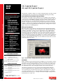
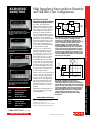
Differential Conductance
Differential conductance measurements are among the most important and critical measurements
made on non-linear tunneling devices and on low temperature devices. Mathematically, differential
conductance is the derivative of a device’s I-V curve. The Model 6220 or 6221, combined with the
Model 2182A Nanovoltmeter, is the industry’s most complete solution for differential conductance
measurements. Together, these instruments are also the fastest solution available, providing 10× the
speed and significantly lower noise than other options. Data can be obtained in a single measurement pass, rather than by averaging the result of multiple sweeps, which is both time-consuming and
prone to error. The Model 622X and Model 2182A are also easy to use because the combination can
be treated as a single instrument. Their simple connections eliminate the isolation and noise current
problems that plague other solutions.
Instruction manual on CD
Getting Started manual (hardcopy)
Software (downloadable)
Accessories Available
LOW LEVEL MEASURE & SOURCE
7006-*
7007-1
7007-2
7078-TRX-5
122
GPIB Cable with Straight-On Connector
Shielded IEEE-488 Cable, 1m (3.3 ft)
Shielded IEEE-488 Cable, 2m (6.6 ft)
5 ft (1.5m), Low Noise, Triax-to-Triax Cable
(Male on Both Ends)
KPCI-488LPA IEEE-488 Interface/Controller for the PCI Bus
KUSB-488B IEEE-488 USB-to-GPIB Interface Adapter
Services Available
6220-3Y-EW
1-year factory warranty extended to 3 years from
date of shipment
6221-3Y-EW 1-year factory warranty extended to 3 years from
date of shipment
C/6220-3Y-ISO 3 (ISO-17025 accredited) calibrations within 3
years of purchase*
C/6221-3Y-ISO 3 (ISO-17025 accredited) calibrations within 3
years of purchase*
*Not available in all countries
Figure 1. Perform, analyze, and display differential conductance measurements.
Delta Mode
Keithley originally developed the delta mode method for making low noise measurements of voltages
and resistances for use with the Model 2182 Nanovoltmeter and a triggerable external current source.
Essentially, the delta mode automatically triggers the current source to alternate the signal polarity,
then triggers a nanovoltmeter reading at each polarity. This current reversal technique cancels out
any constant thermoelectric offsets, ensuring the results reflect the true value of the voltage.
This same basic technique has been incorporated into the Model 622X and Model 2182A delta
mode, but its implementation has been dramatically enhanced and simplified. The technique can
now cancel thermoelectric offsets that drift over time, produce results in half the time of the previous technique, and allow the source to control and configure the nanovoltmeter, so setting up the
measurement takes just two key presses. The improved cancellation and higher reading rate reduces
measurement noise to as little as 1nV.
1.888.KEITHLEY (U.S. only)
www.keithley.com
A Greater Measure of Confidence
6220
6221
4µV
DC
Measurement
Delta Mode
Measurement
Figure 2. Delta mode offers 1000-to-1 noise reduction.
The delta mode enables measuring low voltages and resistances accurately. Once the Model 622X and
the Model 2182A are connected properly, the user simply presses the current source’s Delta button,
followed by the Trigger button, which starts the test. The Model 622X and the Model 2182A work
together seamlessly and can be controlled via the GPIB interface (GPIB or Ethernet with the Model
6221). The free example control software available for the Model 622X includes a tutorial that “walks”
users through the delta mode setup process.
Pulsed Tests
Even small amounts of heat introduced by the measurement process itself can raise the DUT’s temperature, skewing test results or even destroying the device. The Model 6221’s pulse measurement
capability minimizes the amount of power dissipated into a DUT by offering maximum flexibility
when making pulsed measurements, allowing users to program the optimal pulse current amplitude,
pulse interval, pulse width, and other pulse parameters.
The Model 6221 makes short pulses (and reductions in heat dissipation) possible with microsecond
rise times on all ranges. The Model 6221/2182A combination synchronizes the pulse and measurement—a measurement can begin as soon as 16µs after the Model 6221 applies the pulse. The entire
pulse, including a complete nanovolt measurement, can be as short as 50µs. Line synchronization
between the Model 6221 and Model 2182A eliminates power line related noise.
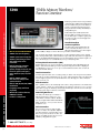
Standard and Arbitrary Waveform Generator
The Model 6221 is the only low current AC source on the market. It can be programmed to generate both basic waveforms (sine, square, triangle, and ramp) and customizable waveforms with
an arbitrary waveform generator (ARB) that supports defining waveforms point by point. It can
generate waveforms at frequencies ranging from 1mHz to 100kHz at an output update rate of
10 megasamples/second.
Performance Superior to AC Resistance Bridges and Lock-In Amplifiers
The Model 622X/2182A combination provides many advantages over AC resistance bridges and lock-in
amplifiers, including lower noise, lower current sourcing, lower voltage measurements, less power
dissipation into DUTs, and lower cost. It also eliminates the need for a current p re-amplifier.
1.888.KEITHLEY (U.S. only)
www.keithley.com
A Greater Measure of Confidence
LOW LEVEL MEASURE & SOURCE
5nV
Models 6220 and 6221 vs.
Homemade Current Sources
Many researchers and engineers who need a
current source attempt to get by with a voltage source and series resistor instead. This is
often the case when an AC current is needed.
This is because, until the introduction of the
Model 6220/6221, no AC current sources were
available on the market. However, homemade
current sources have several disadvantages vs.
true current sources:
• Homemade Current Sources Don’t Have
Voltage Compliance. You may want to be
sure the voltage at the terminals of your
homemade “current source” never exceeds
a certain limit (for example, 1–2V in the
case of many optoelectronic devices). The
most straightforward way to accomplish
this is to reduce the voltage source to that
level. This requires the series resistor to
be reduced to attain the desired current. If
you want to program a different current,
you must change the resistor while the
voltage is held constant! Another possibility
is to place a protection circuit in parallel
with the DUT. These do not have precise
voltage control and always act as a parallel
device, stealing some of the programmed
current intended for the DUT.
• Homemade Current Sources Can’t Have
Predictable Output. With a homemade
“current source” made of a voltage source
and series resistor, the impedance of the
DUT forms a voltage divider. If the DUT
resistance is entirely predictable, the
current can be known, but if the DUT
resistance is unknown or changes, as most
devices do, then the current isn’t a simple
function of the voltage applied. The best
way to make the source predictable is to
use a very high value series resistor (and
accordingly high voltage source), which
is in direct contradiction with the need
for compliance.
• While it’s possible to know (if not control)
the actual current coming from such an
unpredictable source, this also comes at a
cost. This can be done with a supplemental
measurement of the current, such as using
a voltmeter to measure the voltage drop
across the series resistor. This measurement
can be used as feedback to alter the voltage
source or simply recorded. Either way,
it requires additional equipment, which
adds complexity or error. To make matters
worse, if the homemade current source
is made to be moderately predictable by
using a large series resistor, this readback
would require using an electrometer to
ensure accuracy.
Precision low current sourcing
DC Current Source
AC and DC Current Source
123
6220
6221
DC Current Source
AC and DC Current Source
Precision low current sourcing
The Model 6221 can also expand the capabilities
of lock-in amplifiers in applications that already
employ them. For example, its clean signals and
its output synchronization signal make it an
ideal output source for lock-in applications such
as measuring second and third harmonic device
response.
Model 2182A Nanovoltmeter
The Model 2182A expands upon the capabilities
of Keithley’s original Model 2182 Nanovolt
meter. Although the Model 6220 and 6221 are
compatible with the Model 2182, delta mode and
differential conductance measurements require
approximately twice as long to complete with
the Model 2182 as with the Model 2182A. Unlike
the Model 2182A, the Model 2182 does not support pulse mode measurements.
Figure 4. The Model 6221 and the free
example start-up control software make it
easy to create complex waveforms by adding,
multiplying, stringing together, or applying
filters to standard wave shapes.
• Low noise alternative to AC
resistance bridges and lock-in
amplifiers for measuring resistances.
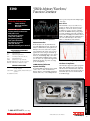
Voltage measurement noise at line frequency
Measurement integration period
Measured response voltage
Measuring difference voltage eliminates
line frequency noise, DC offsets
1/60 second (1/50 when operating off 50Hz power)
Pulsed measurement without line sync
• Easy instrument coordination and
intuitive example software simplifies
setup and operation in many
applications.
• Measure resistances from 10nW to
100MW. One measurement system
for wide ranging devices.
Programmable: 50µs to 12ms
Source Current
•
Applications of
622X/2182A combination:
Line synchronized pulse measurements
• Coordinates pulsing and
measurement with pulse widths as
short as 50µs (6221 only).
• Measures differential conduc
tance up to 10× faster and with
lower noise than earlier solutions
allow. Differential conductance is
an important parameter in semi
conductor research for describing
density of states in bulk material.
LOW LEVEL MEASURE & SOURCE
• Delta mode reduces noise in low
resistance measurements by a factor
of 1000.
124
Figure 3. Measurements are line synchronized to minimize 50/60Hz interference.
• For low impedance Hall measure
ments, the delta mode operation of
the Model 622X/2182A combination
provides industry-leading noise
performance and rejection of contact
potentials. For higher impedance
Hall measurements (greater than
100MW), the Model 4200-SCS can
replace the current source, switching,
and multiple high impedance
voltage measurement channels. This
provides a complete solution with
pre-programmed test projects.
1.888.KEITHLEY (U.S. only)
www.keithley.com
A Greater Measure of Confidence
6220
6221
DC Current Source
AC and DC Current Source
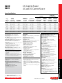
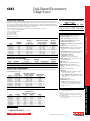
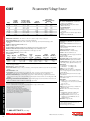
Source Specifications
Settling Time 1, 2
(1% of Final Value)
2nA
0.4 %+
Temperature
Coefficient/°C
0°–18°C &
28°–50°C
Programming
Resolution
Output
Response
Bandwidth
(BW) Into
Short
Typical Noise
(peak-peak)/RMS 3
10Hz–(Bw)
Typical Noise
(peak-peak)/RMS 3
0.1Hz–10Hz
Output
Response
Fast (Typical3)
(6221 Only)
6220, 6221
with Output
Response
Slow (Max.)
2 pA
100fA
0.02 % +200 fA
400 / 80 fA
250 / 50 pA
10k Hz
90 µs
100 µs
20nA
200nA
2µA
20µA
200µA
2mA
20mA
0.3 %+ 10 pA
0.3 %+ 100 pA
0.1 %+ 1 nA
0.05%+ 10 nA
0.05%+100 nA
0.05%+ 1 µA
0.05%+ 10 µA
1pA
10pA
100pA
1nA
10nA
100nA
1µA
0.02 % +200 fA
0.02 % + 2 pA
0.01 % + 20 pA
0.005% +200 pA
0.005% + 2nA
0.005% + 20nA
0.005% +200nA
4 /0.8 pA
20 / 4 pA
200 / 40 pA
2 /0.4 nA
20 / 4 nA
200 / 40 nA
2 /0.4µA
250 / 50 pA
2.5 /0.5 nA
25 /5.0 nA
500 /100 nA
1.0 /0.2 µA
5.0 / 1 µA
20 /4.0 µA
10k Hz
100k Hz
1MHz
1MHz
1MHz
1MHz
1MHz
90 µs
30 µs
4 µs
2 µs
2 µs
2 µs
2 µs
100 µs
100 µs
100 µs
100 µs
100 µs
100 µs
100 µs
100mA
0.1 %+ 50 µA
10µA
0.01 % + 2µA
10 / 2µA
100 / 20 µA
1MHz
3 µs
100 µs
ADDITIONAL SOURCE SPECIFICATIONS
OUTPUT RESISTANCE: >1014W (2nA/20nA range).
OUTPUT CAPACITANCE: <10pF, <100pF Filter ON
(2nA/20nA range).
LOAD IMPEDANCE: Stable into 10µH typical, 100µH for 6220,
or for 6221 with Output Response SLOW.
VOLTAGE LIMIT (Compliance): Bipolar voltage limit set with
single value. 0.1V to 105V in 0.01V programmable steps.
MAX. OUTPUT POWER: 11W, four quadrant source or
sink operation.
GUARD OUTPUT Accuracy: ±1mV for output currents <2mA
(excluding output lead voltage drop).
PROGRAM MEMORY: Number of Locations: 64K. Offers
point-by-point control and triggering, e.g. sweeps.
Max. Trigger Rate: 1000/s.
RMS Noise 10Hz–20MHz (2nA–20mA Range): Less than
1mVrms, 5mVp-p (into 50W load).
Source Notes
1. Settling times are specified into a resistive load, with a maximum
resistance equal to 2V/ I full scale of range. See manual for other
load conditions.
2. Settling times to 0.1% of final value are typically <2× of 1%
settling times.
3. Typical values are non warranted, apply at 23°C, represent the 50th
percentile, and are provided solely as useful information.
2182A Measurement Functions
DUT RESISTANCE: Up to 1GW (1ns) (100MW limit for
pulse mode).
DELTA MODE RESISTANCE MEASUREMENTS and
DIFFERENTIAL CONDUCTANCE: Controls Keithley Model
2182A Nanovoltmeter at up to 24Hz reversal rate (2182 at up
to 12Hz).
PULSE MEASUREMENTS (6221 only):
Pulse Widths: 50µs to 12ms, 1pA to 100mA.
Repetition Interval: 83.3ms to 5s.
Arbitrary function generator
(6221 only)
WAVEFORMS: Sine, Square, Ramp, and 4 user defined arbitrary
waveforms.
Frequency Range: 1mHz to 100kHz.5
FREQUENCY ACCURACY4: ±100ppm (1 year).
Sample Rate: 10 MSPS.
AMPLITUDE: 4pA to 210mA peak-peak into loads up to 1012W.
Amplitude Resolution: 16 bits (including sign).
AMPLITUDE ACCURACY (<10kHz): 5
Magnitude: ±(1% rdg + 0.2% range).
Offset: ±(0.2% rdg + 0.2% range).
SINE WAVE CHARACTERISTICS:
Amplitude Flatness: Less than 1dB up to 100kHz.6
SQUARE WAVE CHARACTERISTICS:
Overshoot: 2.5% max.6
Variable Duty Cycle: 4 Settable to 1µs min. pulse duration,
0.01% programming resolution.
Jitter (RMS): 100ns + 0.1% of period.6
RAMP WAVE CHARACTERISTICS:
Linearity: <0.1% of peak output up to 10kHz.6
ARBITRARY WAVE CHARACTERISTICS:
Waveform Length: 2 to 64K points.
Jitter (RMS): 100ns + 0.1% of period.6
Waveform Notes
4. Minimum realizable duty cycle is limited by current range
response and load impedance.
5. Amplitude accuracy is applicable into a maximum resistive
load of 2V/ I full scale of range. Amplitude attenuation will occur
at higher frequencies dependent upon current range and load
impedance.
6.These specifications are only valid for the 20mA range and a
50W load.
GENERAL
COMMON MODE VOLTAGE: 250V rms, DC to 60Hz.
COMMON MODE ISOLATION: >109W, <2nF.
SOURCE OUTPUT MODES: Fixed DC level, Memory List.
REMOTE INTERFACE:
IEEE-488 and RS-232C.
SCPI (Standard Commands for Programmable
Instruments).
DDC (command language compatible with Keithley
Model 220).
PASSWORD PROTECTION: 11 characters.
DIGITAL INTERFACE:
Handler Interface: Start of test, end of test, 3 category
bits, +5V@300mA supply.
Digital I/O: 1 trigger input, 4 TTL/Relay Drive outputs
(33V@500mA, diode clamped).
OUTPUT CONNECTIONS:
Teflon insulated 3-lug triax connector for output.
Banana safety jack for GUARD, OUTPUT LO.
Screw terminal for CHASSIS.
DB-9 connector for EXTERNAL TRIGGER INPUT,
OUTPUT, and DIGITAL I/O.
Two position screw terminal for INTERLOCK.
INTERLOCK: Maximum 10W external circuit impedance.
POWER SUPPLY: 100V to 240V rms, 50–60Hz.
POWER CONSUMPTION: 120VA.
ENVIRONMENT:
For Indoor Use Only: Maximum 2000m above sea level.
Operating: 0°–50°C, 70%R.H. up to 35°C. Derate
3% R.H./°C, 35°–50°C.
Storage: –25°C to 65°C, guaranteed by design.
EMC: Conforms to European Union Directive 89/336/EEC,
EN 61326-1.
SAFETY: Conforms to European Union Directive
73/23/EEC, EN61010-1.
VIBRATION: MIL-PRF-28800F Class 3, Random.
WARMUP: 1 hour to rated accuracies.
Passive Cooling: No fan.
DIMENSIONS:
Rack Mounting: 89mm high × 213mm wide × 370mm
deep (3.5 in. × 8.375 in. × 14.563 in.).
Bench Configuration (with handle and feet): 104mm
high × 238mm wide × 370mm deep (4.125 in. × 9.375
in. × 14.563 in.).
1.888.KEITHLEY (U.S. only)
www.keithley.com
A Greater Measure of Confidence
Model 6220 and 6221 specifications
Range
(+5% over
range)
Accuracy
(1 Year)
23°C ±5°C
±(% rdg. + amps)
LOW LEVEL MEASURE & SOURCE
6221 Only
125
System switch with high performance multimeter
Series 3700A
System Switch/Multimeter
and Plug-In Cards
A Series 3700A system combines the functionality of an
instrument grade relay switching system with a high performance multimeter. Integrating the multimeter within the
mainframe ensures you of a high quality signal path from
each channel to the multimeter. This tightly integrated
switch and measurement system can meet the demanding
application requirements of a functional test system or
provide the flexibility needed in stand-alone data acquisition and measurement applications. It is ideal for multiple
pin count applications where relay switching can be used
to connect multiple devices to source and measurement
instruments.
The high performance multimeter in the Series 3700A
offers low noise, high stability 3½- to 7½-digit readings
for leading-edge measurement performance. This flexible resolution supplies a DC reading rate from >14,000
readings/second at 3½ digits to 60 readings/second at 7½
digits, offering customers maximum reading throughput
and accuracy. The multimeter also provides an expanded
low ohms (1W) range, low current (10µA) range, and dry
circuit (1W to 1kW) range, extending utility beyond typical
DMM applications.
• Combines the functions of
a system switch and a high
performance multimeter
• LXI Class B compliance with
IEEE 1588 time synchronization
• 3½- to 7½-digit measurement
resolution
• Embedded Test Script Processor
(TSP®) offers unparalleled
system automation, throughput,
and flexibility
The multimeter supports 13 built-in measurement functions, including: DCV, ACV, DCI, ACI, frequency, period, two-wire ohms, four-wire ohms, three-wire RTD temperature, four-wire RTD temperature,
thermocouple temperature, thermistor temperature, and continuity. In-rack calibration is supported,
which reduces both maintenance and calibration time. Onboard memory can store up to 650,000
readings, and the USB device port provides easy transfer of data to memory sticks.
Single-Channel Reading Rates
Resolution
7½ Digits (1 NPLC)
6½ Digits (0.2 NPLC)
5½ Digits (0.06 NPLC)
4½ Digits (0.006 NPLC)
3½ Digits (0.0005 NPLC)
• Extended low ohms (1W) range
with 100nW resolution
• Extended low current (10µA)
range with 1pA resolution
126
• Low noise, <0.1ppm rms noise
on 10VDC range
• Expanded dry circuit range
(2kW)
• Four-wire open lead detection
(source and sense lines)
For more information about Series 3700A
systems, see page 162.
• Power supply burn-in testing
(PC, network, telecom)
• Plant/environment monitoring
and control
2.0
1.0
• Automotive and aerospace
systems
0.0
–1.0
• Consumer product certification/
testing laboratories
–2.0
–3.0
–4.0
• System- and rack-level signal
referencing
• Temperature profiling
Leading Competitor
Keithley 3706A
3.0
• Applications
• Low ohms testing (contacts,
connectors, relays)
Low Noise Performance
Model 3706A vs. Leading Competitor
4.0
10VDC Noise (ppm of range)
LOW LEVEL MEASURE & SOURCE
• >14,000 readings/second
DCV/
2-Wire Ohms 4-Wire Ohms
60
29
295
120
935
285
6,200
580
14,000
650
0.0
5.0
10.0
15.0
20.0
25.0
30.0
35.0
1000 Readings at 1PLC
Compare the Model 3706A’s 10V DC noise
and speed performance with that of the
leading competitor. All the data was taken at
1PLC with a low thermal short applied to the
input, which resulted in 10× lower noise and
7× faster measurements for the Model 3706A.
1.888.KEITHLEY (U.S. only)
www.keithley.com
A Greater Measure of Confidence
Low Current/High Resistance
Measurements
An ammeter is an instrument for measuring electric
current flow, calibrated in amperes. There are two
main types of ammeter architectures: shunt ammeters and feedback ammeters.
of the DUT. A shunt ammeter’s voltage burden is typically on the order of hundreds of m
illivolts.
Shunt Ammeters: DMMs
Shunt ammeters are the most common ammeter
type and are found in almost all digital multimeters
(DMMs). These meters measure current by developing a voltage at the input terminal that is proportional to the current being measured (Figure 1).
DMM (shunt) ammeter
+
–
I
VBURDEN
= 200mV at
full scale
A/D
RSHUNT
Figure 1
The main drawback associated with shunt ammeters
is their fundamentally high input impedance
design. This drawback becomes more significant
with decreasing current, because a larger shunt
resistor must be used in order to develop a
measurable voltage. However, as long as the shunt
resistor is significantly smaller than the resistance
of the DUT and the currents to be measured are
not very small (not much lower than microamp
level [10 –6A]), shunt ammeters work fine.
Sources of Generated Current Error
–
A/D
+
I
VOFFSET
Total voltage
burden<0.2mV
CAL VOFFSET
Figure 2
Feedback Ammeter
Feedback ammeters are closer to “ideal” than shunt
ammeters, and should be used for current measurements of microamps or less (10 –6A) or where it is
especially critical to have an ammeter with low input
impedance. Instead of developing a voltage across the
terminals of the ammeter, a feedback ammeter develops a voltage across the feedback path of a high gain
operational amplifier (Figure 2). This voltage is also
proportional to the current to be measured; however,
it is no longer observed at the input of the instrument, but only through the output voltage of the opamp. The input voltage is equal to the output voltage
divided by the op-amp gain (typically 100,000), so
the voltage burden has now typically been reduced
to microvolts. The feedback ammeter architecture
results in low voltage burden, so it produces less
error when measuring small currents and when
measuring currents generated by low impedance
devices. Keithley electrometers and picoammeters
employ feedback ammeter technology.
300mV – VBURDEN
Voltage Burden
The terminal voltage of an ammeter is called the voltage burden. This voltage burden developed across
the meter could result in significantly lower current
through the load than before the meter was inserted,
therefore, the ammeter can’t read the current it was
intended to measure.
Figure 3
An ideal ammeter would not alter the current flowing
in the circuit path, so it would have zero resistance
and zero voltage burden. A real ammeter will always
introduce a non-zero voltage burden. In general, the
error term caused by an ammeter is stated as the
ammeter’s voltage burden divided by the resistance
Figure 3 illustrates the problems caused by high voltage burden when measuring the emitter current of
a transistor. Even though the basic current measurement could be well within the measuring capability
of the DMM, the DMM’s voltage burden significantly
reduces the voltage applied to the DUT, resulting in
1V
0.7V
I
VBURDEN
Low current measurements are subject to a number
of error sources that can have a serious impact on
measurement accuracy. All ammeters will generate
some small current that flows even when the input is
open. These offset currents can be partially nulled by
enabling the instrument current suppress. External
leakage currents are additional sources of error;
therefore, making properly guarded and/or shielded
connections is important. The source impedance of
the DUT will also affect the noise performance of
the ammeter. In addition, there are other extraneous
generated currents in the test system that could add
to the desired current, causing errors. The following paragraphs discuss various types of generated
currents and how to minimize their impact on the
measurements.
I
+
Frictional motion
at boundary due
to cable motion
–
Insulation
+
I
–
Coaxial
Cable
Outer
Jacket
Inner
Conductor
Outer
Shield
Conductive
lubricant in
low noise
cable
Figure 4
Triboelectric effects are created by charge imbalance due to frictional effects between a conductor
and an insulator, as shown in Figure 4. Keithley’s
low noise cables greatly reduce this effect by introducing an inner insulator of polyethylene coated with
graphite underneath the outer shield. The graphite
provides lubrication and a conducting equipotential
cylinder to equalize charges and minimize the charge
generated.
Piezoelectric currents are generated when mechanical stress is applied to certain crystalline materials
when used for insulated terminals and interconnecting hardware. In some plastics, pockets of stored
charge cause the material to behave in a manner
similar to piezoelectric materials. An example of a
terminal with a piezoelectric insulator is shown in
Figure 5. To minimize the current due to this effect,
remove mechanical stresses from the insulator and
use insulating materials with minimal piezoelectric
and stored charge effects.
1.888.KEITHLEY (U.S. only)
www.keithley.com
A Greater Measure of Confidence
LOW LEVEL MEASURE & SOURCE
Shunt vs. Feedback Ammeters
Shunt ammeters are the most common type and
work in many applications; feedback ammeters are
more appropriate when measuring small currents;
their use is growing because the typical magnitude of
the test currents used today is decreasing. However,
choosing the proper ammeter depends not only on
the magnitude of the current, but also on characteristics (most typically, the impedance) of the device
under test (DUT).
Picoammeter/Electrometer
lower measured emitter current than intended. If a
picoammeter or electrometer were used instead, the
voltage burden would cause a negligible change in
emitter current.
Technical information: Low current/high resistance measurements
Technical
Information
127
Technical
Information
I
Epoxy Printed
Circuit Board
Flux or
other chemical
“track” and
moisture
+
–
I
Figure 6
Contamination and humidity can produce error
currents, which arise from electrochemical effects
that occur when contaminants (in the form of ionic
chemicals) create weak “batteries” between two conductors on a circuit board. For example, commonly
used epoxy printed circuit boards, if not thoroughly
cleaned of etching solution, flux, oils, salts (e.g.,
fingerprints) or other contaminants, can generate
currents of a few nanoamps between conductors (see
Figure 6). To avoid the effects of contamination and
humidity, select insulators that resist water absorp-
Leakage currents are typical
sources of error in high
resistance measurements. They
are generated by unwanted
high resistance paths (leakage
resistance) between the
measurement circuit and nearby
voltage sources; they can be
reduced by employing proper
guarding techniques, using
clean, quality insulators, and
minimizing humidity.
Typical resistance values of
various insulating materials are
shown in Figure 8. Absorbed
moisture may also change the
PROPERTY
Volume
Resistivity
(Ohm-cm)
1018 Ω
10–12
10–13
Dirty
surface
1015 Ω
10–14
Resistance
1011 Ω
Ceramics
1010 Ω
1012Ω
Triboelectric
Effects
109 Ω
Piezoelectric
Effects
Electrochemical Resistor
Effects
Noise
in 1Hz
Bandwidth
Current-Generating Phenomena
Figure 7
G-10
1012 Ω
109Ω
10–15
1014 Ω
1013 Ω
Clean
surface
Teflon
+
–
+
0
0
0
0
0
0
+
1016 Ω
Epoxy
board
Low
Noise
Cable
+
+
0
0
+
–
–
–
+
–
0
–
0
–
–
+
–
–
0
+
Table 1
1017 Ω
10–10
Typical
Current
–11
Generated 10
Sapphire
Teflon®
Polyethylene
Polystyrene
Kel-F®
Ceramic
Nylon
Glass Epoxy
PVC
Phenolic
KEY: + Material very good in regard to the property.
0 Material moderately good in regard to the property.
– Material weak in regard to the property.
10–8
Standard
Cable
Material
1016 – 1018Ω
1017 – 1018Ω
1014 – 1018Ω
1012 – 1018Ω
1017 – 1018Ω
1012 – 1014Ω
1012 – 1014Ω
1010 – 1017Ω
1010 – 1015Ω
105 – 1012Ω
10–7 A
10–9
Resistance
Minimal
Minimal
to Water
Piezoelectric Triboelectric
Absorption
Effects
Effects
PVC
108 Ω
Insulating Material
Figure 8
1.888.KEITHLEY (U.S. only)
www.keithley.com
A Greater Measure of Confidence
Polyethylene
Polystyrene
Printed
Wiring
Sapphire
Figure 5
The Alternating Polarity Method can virtually
eliminate the effects of background currents in the
sample. In this method, a bias voltage of positive
polarity is applied, then the current is measured after
a predetermined delay. Next, the polarity is reversed
and the current is measured again, using the same
delay. The polarity reversal process can be repeated
any number of times. The resistance is calculated
based on a weighted average of the most recent current measurements.
Ceramics
Nylon
Conductive
Plate
Piezoelectric
Insulator
High Resistance Measurements
For high resistance measurements (>1GW), a
constant voltage is most often applied across the
unknown resistance. The resulting current is
measured from an ammeter placed in series, and the
resistance can be found using Ohm’s law (R= V/I).
This method of applying a voltage and measuring
the current (as opposed to applying a current and
measuring the voltage), is preferred for high resistance measurements, because high resistances often
change as a function of applied voltage. Therefore,
it’s important to measure the resistance at a relevant
and controllable voltage. This method most often
requires measuring low currents using an electrometer or picoammeter. All the low current techniques
and error sources described in previous paragraphs
also apply here.
Teflon
–
Alternating Polarity Method
When measuring materials with very high resistivity,
background currents may cause significant measurement errors. They may be due to charge stored in the
material (dielectric absorption), static or triboelectric
charge, or piezoelectric effects.
Paper
+
Figure 7 summarizes approximate magnitudes of the
various currents.
Phenolic
I
Epoxy
board
Technical information: Low current/high resistance measurements
LOW LEVEL MEASURE & SOURCE
I
+
–
resistance of certain insulators by orders of magnitude. Table 1 shows a qualitative description of water
absorption and other effects.
tion and keep humidity to moderate levels. Also, keep
all insulators clean and free of contamination.
Metal
Terminal
Applied
Force
128
Low Current/High Resistance
Measurements
Selector Guide
Picoammeters
MODEL
Source
Measure
Unit (SMU)
Instruments
Electrometers
6482
6485
6487
2502
6514
6517B
6430
131
134
137
141
144
148
44
From1
20 fA
20 fA
20 fA
15 fA
<1 fA
<1 fA
400 aA
To
20 mA
20 mA
20 mA
20 mA
20 mA
20 mA
100 mA
From2
10 µV
10 µV
10 µV
To
200 V
200 V
200 V
Page
CURRENT MEASURE
VOLTAGE MEASURE
RESISTANCE MEASURE4
From5
10 W
10 W
100 W
100 µW
To6
1 PW
200 GW
10 PW3
10 PW3
From2
10 fC
10 fC
To
20 µC
2 µC
CHARGE MEASURE
FEATURES
3 Slot Triax
BNC
3 Slot Triax
3 Slot Triax
3 Slot Triax
3 Slot Triax
3 Slot Triax
IEEE-488
•
•
•
•
•
•
•
RS-232
•
•
•
•
•
•
•
•
•
•
Input Connection
Guard
CE
Other
•
•
•
•
•
•
•
6½ digits.
Dual ±30V
bias sources.
5½ digits.
Autoranging.
1000 rdg/s.
5½ digits. Builtin 500V source.
Alternating voltage
method for
HI-R sweeps.
5½ digits.
Dual channel. Builtin 100V source per
channel.
5½ digits. Replaces
Models 6512,
617-HIQ.
5½ digits. Builtin ±1kV source.
Temperature,
RH measurements.
Alternating polarity
method for HI-R.
Plug-in switch
cards available.
Replaces 6517A.
SourceMeter with
Remote PreAmp to
minimize
cable noise.
Notes
1. Includes noise.
2. Digital resolution limit. Noise may have to be added.
3.PW (Petaohms) = 1015W.
4. Resistance is measured with the Model 237 using Source V/Measure I or Source I/Measure V, but not directly displayed.
5. Lowest resistance measurable with better than 1% accuracy.
6. Highest resistance measurable with better than 10% accuracy.
1.888.KEITHLEY (U.S. only)
www.keithley.com
A Greater Measure of Confidence
LOW LEVEL MEASURE & SOURCE
Selector Guide: Picoammeters, Electrometers, Source Measure Unit (SMU) Instruments
(Measurement)
Selector guide: Picoammeters, electrometers, source-measure units (measurement)
Low Current/High Resistance
Measurements
129
Selector Guide
Low Current/High Resistance
Measurements
Selector Guide: Sources and Source Measure Unit (SMU) Instruments (Sourcing)
Selector guide: Sources and source-measure units (sourcing)
Current Sources
Voltage Source
MODEL
Page
Current Source
Voltage Source
Sink
CURRENT OUTPUT
6220
121
•
6221
121
•
•
•
Accuracy1
2 pA
2 pA DC
4 pA AC
100 fA
(DC & AC)
±105 mA
Resolution2
100 fA
Maximum
VOLTAGE OUTPUT
From
To
±105 mA
POWER OUTPUT
11 W
11 W
CURRENT LIMIT
VOLTAGE LIMIT
105 V
105 V
ACCURACY (±Setting)
I
V
0.05%
0.05%
248
335
•
•
Source Measure Unit (SMU)
Instruments
2657A
6430
32
44
120 mA
•
3000 V
•
180 W
•
0.03%
10 fA
1 fA
50 aA
±120 mA
±105 mA
±1.5 V
±5000 V
±100 µV
±3000 V
±5 µV
±210 V
25 W
180 W
2.2 W
5.25 mA
120 mA
1 fA to 105 mA
0 to 5000 V
3000 V
0.2 mV to 210 V
0.01%
0.03%
0.03%
0.03%
0.02%
SHV High
Voltage Coax
HV Triax
3 Slot Triax
FEATURES
LOW LEVEL MEASURE & SOURCE
Output Connector
130
Ethernet
RS-232
IEEE-488
Memory
Remote Sense
Current Source Guard
CE
Other
3 Slot Triax
3 Slot Triax
•
•
65,000 pt.
•
•
•
65,000 pt.
•
•
•
•
AC and DC current
Controls 2182A for
low-power resistance source. ARB waveforms
and I-V measurements. up to 100kHz. Controls
2182A like 6220, adds
pulsed I-V.
LXI compliant
•
•
Voltage monitor
output.
Programmable
voltage limit.
•
250K readings
•
•
•
Source/measure
capability. Pulse
mode. USB port.
1. Best absolute accuracy of source.
2. Resolution for lowest range, smallest change in current that source can provide.
1.888.KEITHLEY (U.S. only)
www.keithley.com
A Greater Measure of Confidence
•
•
2500 pt.
•
•
•
The Model 6482 Dual-Channel Picoammeter/Voltage
Source provides two independent picoammeter/
voltage source channels for a wide range of low-level
measurement applications that require dual-channel
measurements. Building off of the proven measurement capabilities of Keithley’s Model 6485 5½-digit
Picoammeter, the Model 6482 adds higher measurement resolution, a second measurement channel,
and dual, independent 30V voltage bias sources.
With its dual channel measurement capabilities, the
Model 6482 is a great measurement tool for analyzing multi-channel devices, monitoring currents
in multiple locations on materials, and recording
data from multiple sensors at once. The dual channels facilitate easier control and data aggregation.
The greater channel density increases the number
of instruments (and channels) that can fit in confined spaces.
• Dual-channel, 6½-digit
measurement capability
• Dual ±30V bias sources
• Measure currents up to 20mA
• Measure currents with 1fA
resolution
• 0–10V analog output for high
resolution measurement
feedback
• Supports assembly process,
final testing, parts binning, and
specification
• 3000-point buffer memory
on each channel allows data
transfer after test completion
• Trigger Link for binning and
sweep test operations
Programmable Limits and Filters
As with most Keithley instruments, the Model 6482’s current and voltage limits can be programmed
to ensure device protection during critical points, such as start of test. These instruments also provide average and median filters, which can be applied to the data stored in the buffer memory.
Ratio and Delta Measurements
The Model 6482 can provide ratio or delta measurements between the two completely isolated channels. These functions can be accessed via either the front panel or the GPIB interface. For test setups
with multiple detectors, this capability enables targeted control capabilities.
Features that Expand Test and Measurement Flexibility
• Scaled voltage analog output. The Model 6482 can transmit measurement results to devices such
as DMMs, data acquisition boards, oscilloscopes, or strip chart recorders.
• 220V overload protection. With this high overload protection and a robust design, the Model
6482 can withstand abusive overflows.
• One-touch front panel design. Functions can be configured easily with the push of a button without complicated function menus.
• Built-in Trigger Link interface. The Trigger Link interface simplifies synchronizing the Model
6482 with other instruments and voltage sources and combines six independent selectable trigger
lines on a single connector for simple, direct control over all instruments in a system.
• IEEE-488 and RS-232 interfaces
• RS-232 and IEEE-488 interfaces. These interfaces make it easy to integrate the Model 6482 into
automated test and measurement systems.
APPLICATIONS
• Display on/off switch. For research on light-sensitive components, such as measuring the dark
currents of photodiodes, the front panel display can be switched off to avoid introducing light that
could significantly reduce the accuracy of the results.
• Manufacturing component test
• Dual diode testing
• Semiconductor component
testing
• Multi-pin component testing
Dual-channel picoammeter/voltage source
Dual-Channel Picoammeter/
Voltage Source
• REL and LOG functions. The Model 6482 can make relative readings with respect to a baseline
value or display the logarithm of the absolute value of the measured current.
• Rear panel triax inputs. Triax inputs ensure premium noise protection. Triax-to-BNC adapters,
which are included, allow inexpensive, easy-to-use BNC cables to be employed in situations where
noise is less of a concern.
• Ion beam monitoring
• Electron microscopy
1.888.KEITHLEY (U.S. only)
www.keithley.com
A Greater Measure of Confidence
LOW LEVEL MEASURE & SOURCE
Dual-channel picoammeter/voltage source
6482
131
Ordering Information
LOW LEVEL MEASURE & SOURCE
Dual-channel picoammeter/voltage source
6482 132
6482/E
6482/J
Dual Channel
Picoammeter/Voltage
Source (120V line
power voltage)
Dual Channel
Picoammeter/Voltage
Source (220-240V
line power voltage)
Dual Channel
Picoammeter/Voltage
Source (100V line
power voltage)
Accessories Supplied
7078-TRX-BNC
Triax-to-BNC
Connector (2×)
Dual-Channel Picoammeter/
Voltage Source
Accessories Available
CABLES
237-ALG-*
4802-10
4803
7007-1
7007-2
7007-4
7078-TRX-*
7009-5
7754-3
8607
8501-1
8501-2
8503
ADAPTERS
237-TRX-BAR
7078-TRX-BNC
CS-565
Services Available
6482-3Y-EW
Low Noise Triax Cable with Alligator Clips
Low Noise BNC Input Cable, 3m (10 ft)
Low Noise Cable Kit
Shielded IEEE-488 Cable, 1m (3.3 ft)
Shielded IEEE-488 Cable, 2m (6.6 ft)
Shielded IEEE-488 Cable, 4m (13.1 ft)
3-Slot Triax Cable
RS-232 Cable
BNC to Alligator Cable, 0.9m (3 ft)
Banana Cable set for Analog Output
Trigger Link Cable with Male Micro-DIN
Connectors at each End, 1m (3.3 ft)
Trigger Link Cable with Male Micro-DIN
Connectors at each End, 2m (6.6 ft)
DIN-to-BNC Trigger Cable
1 Year Factory Warranty extended to 3 years
from date of shipment
6482-5Y-EW
1 Year Factory Warranty extended to 3 years
from date of shipment
C/6482-3Y-DATA 3 (Z-540-1 compliant) calibrations within 3
years of purchase for Model 6482
C/6482-5Y-DATA 5 (Z-540-1 compliant) calibrations within 5
years of purchase for Model 6482
C/6482-3Y-ISO 3 (ISO-17025 accredited) calibrations within 3
years of purchase for Model 6482
C/6482-5Y-ISO 5 (ISO-17025 accredited) calibrations within 5
years of purchase for Model 6482
3-lug Triax Barrel
Female BNC to 3-Slot Male Triax for connecting
BNC cable into triax fixture
BNC Barrel
RACK MOUNT KITS
4288-1
Single Fixed Rack Mounting Kit
4288-2
Dual Fixed Rack Mounting Kit
GPIB INTERFACES
KPCI-488LPA
IEEE-488 Interface/Controller for the PCI Bus
KUSB-488B
IEEE-488 USB-to-GPIB Interface Adapter
1.888.KEITHLEY (U.S. only)
www.keithley.com
A Greater Measure of Confidence
Dual-channel picoammeter/voltage source
6482
6482
Dual-Channel Picoammeter/
Voltage Source
Typical Speed and Noise Rejection
Digits
4½
5½
6½
Range
2.000000 nA
20.00000 nA
200.0000 nA
2.000000 μA
20.00000 μA
200.0000 μA
2.000000 mA
20.00000 mA
Accuracy 1, 2
23° ±5°C
±(% rdg + offset)
1.00% + 2 pA
0.40% + 2 pA
0.30% + 200 pA
0.20% + 200 pA
0.10% + 20 nA
0.10% + 20 nA
0.10% + 2 μA
0.10% + 2 μA
Temperature Coefficient
0°–18°C & 28°–50°C
±(%rdg + offset)/°C
0.01 + 200 fA
0.01 + 200 fA
0.02 + 20 pA
0.02 + 20 pA
0.01 + 2 nA
0.01 + 2 nA
0.02 + 200 nA
0.02 + 200 nA
Resolution
<400 μV
<4 mV
Accuracy
23°C ±5°C
±(0.15% of setting + 5 mV)
±(0.3% of setting + 50 mV)
Maximum
Current
20 mA
20 mA
Load Regulation 4
< 0.30%, 0 to 20 mA
< 0.30%, 0 to 20 mA
DC Input
Impedance3
(maximum)
20kW
20kW
200
W
200
W
2.0
W
2.0
W
0.2
W
0.2
W
Temperature
Coefficient
150 ppm/°C
300 ppm/°C
Analog Output Specifications
Output voltage range (output is inverting) 2: –10V out for positive full scale input, +10V out for negative full scale input.
Output impedance: 1kW typical.
Accuracy
23°C ±5°C
Range
±(% rdg. + offset)
2.000000 nA
6.0% + 90 mV
20.00000 nA
3.0% + 9 mV
200.0000 nA
6.0% + 90 mV
2.000000 μA
3.0% + 9 mV
20.00000 μA
6.0% + 90 mV
200.0000 μA
2.5% + 9 mV
2.000000 mA
6.0% + 90 mV
20.00000 mA
2.5% + 9 mV
Temperature Coefficient
0°–18°C & 28°–50°C
±(%rdg. + offset)/°C
0.30% + 7 mV
0.11% + 700 μV
0.30% + 4 mV
0.11% + 400 μV
0.30% + 4 mV
0.11% + 400 μV
0.30% + 4 mV
0.11% + 400 μV
Typical Rise Time
(10% to 90%)
6.1 ms
6.1 ms
395 μs
395 μs
135 μs
135 μs
21 μs
21 μs
Typical Noise Floor Measurement Specifications
Range
2.000000 nA
20.00000 nA
200.0000 nA
2.000000 μA
20.00000 μA
200.0000 μA
2.000000 mA
20.00000 mA
0.01 NPLC
2.5 pA
2.5 pA
200 pA
200 pA
20 nA
20 nA
2 μA
2 μA
Typical Noise Floor
RMS (1 STDEV), 100 Samples
0.1 NPLC
1.0 NPLC
1.5 pA
45 fA
1.5 pA
45 fA
120 pA
2 pA
120 pA
2 pA
12 nA
200 pA
12 nA
200 pA
1.5 μA
25 nA
1.5 μA
25 nA
10 NPLC
15 fA
15 fA
500 fA
500 fA
50 pA
50 pA
5 nA
5 nA
NMRR
—
—
60 dB
GENERAL
Voltage Bias Specifications
Range
±10 V
±30 V
NPLC
0.01
0.1
1
Source capacitance: Stable to 10.0nF (typical).
Input bias current 5: 50fA max. @ 23°C.
Input voltage burden 6: 4.0mV maximum.
Voltage source slew rate: 3.0ms/V (typical).
Common mode voltage: 200VDC.
Common mode isolation: Typically 109W in parallel
with 150nF.
Overrange: 105% of measurement range.
Memory buffer: 6000 readings (two 3000 point buffers). Includes selected measured value(s) and time
stamp.
Programmability: IEEE-488.2, RS-232, five user-definable power-up states plus factory default and *RST.
Output enable connector:
Output Enable: Active low input.
Input line: SOT (start of test) trigger input.
Power supply: 100V, 120V, 220V, 240V (±10%), 50Hz or
60Hz, 50VA maximum.
Warranty: 1 year.
EMC: Conforms to European Union EMC Directive.
Vibration: MIL-T-28800F random class 3.
Safety: Conforms to European Union Low Voltage
Directive.
Warm-up: 1 hour to rated accuracy.
Dimensions:
Rack Mount: 89mm high × 213mm wide × 370mm
deep (3.5 in. × 8.4 in. × 14.6 in.).
Bench Configuration (with handle and feet): 104mm
high × 238mm wide × 370mm deep (4.1 in. × 9.4 in.
× 14.6 in.).
Weight: 23.1kg (10.5 lb.).
Environment: For indoor use only.
Altitude: Maximum 2000m (6562 ft.) above sea level.
Operating: 0° to 50°C, 70 % relative humidity up to
35°C. Derate 3% relative humidity/°C, 35° to 50°C.
Storage: –25° to 65°C.
Measurement SPECIFICATIONS1
Maximum
Resolution
1 fA
10 fA
100 fA
1 pA
10 pA
100 pA
1 nA
10 nA
Readings per Second
GPIB
GPIB
(SCPI)
(488.1)
700
900
60
475
58
58
notes
1.
2.
3.
4.
5.
6.
Speed = Normal (1.0 NPLC), filter on.
One year.
Measured as DVin/∆Iin at full scale (and zero) input currents.
Measured as DVin/∆Iin at full scale (20mA) and zero load currents.
Specification by design.
Measured (at input triaxial connector) as DVin at full scale (20mA)
versus zero input currents.
1.888.KEITHLEY (U.S. only)
www.keithley.com
A Greater Measure of Confidence
Model 6482 specifications
This document contains specifications and supplemental information for the Model 6482 Dual-Channel Picoammeter/Voltage Source
instrument. Specifications are the standards against which the Model 6482 is tested. Upon leaving the factory, the Model 6482 meets
these specifications. Supplemental and typical values are nonwarranted, apply at 23°C, and are provided solely as useful information.
The Model 6482 provides two independent picoammeter/voltage source channels for a wide range of measurement applications. The
Model 6482 includes an analog output jack on the rear panel for each channel.
Source and measurement accuracies are specified at the Model 6482 terminals under these c onditions:
1. 23° ± 5°C, <70 percent relative humidity.
2. After a one-hour warm-up period.
3. Speed normal (1 NPLC).
4. A/D autozero enabled.
5. Properly zeroed operation.
6. Calibration period: One year.
LOW LEVEL MEASURE & SOURCE
Dual-channel picoammeter/voltage source
Specification Conditions
133
The 5½-digit Model 6485 Picoammeter combines
Keithley’s expertise in sensitive current measurement instrumentation with enhanced speed and
a robust design. With eight current measurement
ranges and high speed autoranging, this costeffective instrument can measure currents from 20fA
to 20mA, taking measurements at speeds up to 1000
readings per second.
The Model 6485’s 10fA resolution and superior
sensitivity make it well suited for characterizing low
current phenomena, while its 20mA range lets it
measure currents high enough for applications such
as measuring 4-20mA sensor loops.
• Cost-effective low current
measurement solution
• 10fA resolution
• 5½-digit resolution
• <200µV burden voltage
• Up to 1000 readings/second
• Built-in Model 485 emulation
mode
• IEEE-488 and RS-232 interfaces
LOW LEVEL MEASURE & SOURCE
• Analog output
134
Picoammeter
Although it employs the latest current measurement
technology, it is significantly less expensive than
other instruments that perform similar functions,
such as optical power meters, competitive pico
ammeters, or user-designed solutions. With a price that’s comparable to a general purpose DMM,
the Model 6485 makes picoamp-level measurements affordable for virtually any laboratory or
production floor.
Low Voltage Burden and Higher Accuracy
While DMMs typically employ shunt ammeter circuitry to measure current, the Model 6485 is a feedback picoammeter. This design reduces voltage burden by several orders of magnitude, resulting in a
voltage burden of less than 200µV on the lower measurement ranges. The low voltage burden makes
the Model 6485 function much more like an ideal ammeter than a DMM, so it can make current
measurements with high accuracy, even in circuits with
Model 485
Model 6485
very low source voltages.
Current Ranges
2nA–2mA
2nA–20mA
200µV (1mV on
Voltage Burden
200µV
Successor to the Model 485
20mA range)
Reading Rate
3/s
1000/s
The Model 6485 builds on the strengths of one of
Digits
4½
5½
Keithley’s most popular picoammeters, the Model 485,
Output
Yes
Yes
offering an additional 20mA measurement range, as well Analog
Battery Option
Yes
No
as much higher measurement speeds. With a top speed
Storage Buffer
100 points
2500 points
of up to 1000 readings per second, the Model 6485 is
the fastest picoammeter Keithley has ever made. It offers ten times greater resolution than the Model
485 on every range. A time-stamped 2500-reading data buffer provides minimum, maximum, and
standard deviation statistics. A built-in emulation mode simplifies upgrading existing applications
originally configured with a Model 485. This emulation mode makes it possible to control the Model
6485 with any custom code written to control the Model 485. Refer to the comparison table for
additional information.
When do you need a picoammeter?
Measuring low DC currents often demands a lot more than a digital
multimeter (DMM) can deliver. Generally, DMMs lack the sensitivity required
to measure currents less than 100nA. Even at higher currents, a DMM’s
input voltage drop (voltage burden) of hundreds of millivolts can make
accurate current measurements impossible. Electrometers can measure
low currents very accurately, but the circuitry needed to measure extremely
low currents, combined with functions like voltage, resistance, and charge
measurement, can increase an electrometer’s cost significantly. The Model
6485 Picoammeter combines the economy and ease of use of a DMM with
low current sensitivity near that of an electrometer.
1.888.KEITHLEY (U.S. only)
www.keithley.com
A Greater Measure of Confidence
Measures low currents quickly, accurately, and economically
Measures low currents quickly, accurately, and economically
6485
Measures low currents quickly, accurately, and economically
6485Picoammeter
Accessories Supplied
CAP-18 Protective Shield/
Cap (2-lug)
4801Low Noise BNC Input
Cable, 1.2m (4 ft)
Features that Expand Test and Measurement Flexibility
• Scaled voltage analog output. This output allows the Model 6485 to transmit measurement
results to devices like DMMs, data acquisition boards, oscilloscopes, or strip chart recorders.
• 220V overload protection. This high overload protection and a robust design let the Model 6485
withstand abusive overflows.
• One-touch front panel design. Functions can be configured easily with the push of a button,
without complicated function menus.
• Built-in Trigger Link interface. The Trigger Link interface simplifies synchronizing the Model
6485 with other instruments and voltage sources. This interface combines six independent
selectable trigger lines on a single connector for simple, direct control over all instruments
in a system.
• RS-232 and IEEE-488 interfaces. These interfaces make it easy to integrate the Model 6485 into
automated test and measurement systems.
• Display on/off switch. For research on light-sensitive components, such as measuring the dark
currents of photodiodes, the front panel display can be switched off to avoid introducing light that
could significantly reduce the accuracy of the results.
• REL and LOG functions. The Model 6485 can make relative readings with respect to a baseline
value or display the logarithm of the absolute value of the measured current.
• Resistance calculations. The Model 6485 can calculate resistance by dividing an externally
sourced voltage value by the measured current.
APPLICATIONS
• Beam monitoring and radiation
monitoring
• Leakage current testing in
insulators, switches, relays, and
other components
• SEM beam current
measurements
• Galvanic coupling
measurements
• Optoelectronic device testing
and characterization
• Optical fiber alignment
• Circuit test and analysis in
DCLF circuits
• Sensor characterization
• I-V measurements of
semiconductors and other
devices
• Nanoelectronic device
characterization
• Rear panel BNC inputs. Inexpensive, easy-to-use BNC cables can be employed, rather than more
expensive triax cables.
ACCESSORIES AVAILABLE
Cables
4802-10 Low Noise BNC Input Cable, 3m (10 ft)
4803
Low Noise Cable Kit
7007-1 Shielded IEEE-488 Cable, 1m (3.3 ft)
7007-2 Shielded IEEE-488 Cable, 2m (6.6 ft)
7007-4 Shielded IEEE-488 Cable, 4m (13.1 ft)
7009-5 RS-232 Cable
7754-3 BNC to Alligator Cable, 0.9m (3 ft)
8607
Banana Cable set for Analog Output
8501-1 Trigger Link Cable with Male Micro-DIN Connectors at
each End, 1m (3.3 ft)
8501-2 Trigger Link Cable with Male Micro-DIN Connectors at
each End, 2m (6.6 ft)
8503
DIN-to-BNC Trigger Cable
Services Available
6485-3Y-EW
1-year factory warranty extended to 3 years from
date of shipment
C/6485-3Y-ISO 3 (ISO-17025 accredited) calibrations within 3
years of purchase*
*Not available in all countries
Adapters
CS-565
BNC Barrel
7078-TRX-BNCFemale BNC to 3-Slot Male Triax for connecting
BNC cable into triax fixture
Rack Mount Kits
4288-1
Single Fixed Rack Mounting Kit
4288-2
Dual Fixed Rack Mounting Kit
GPIB Interfaces
KPCI-488LPA IEEE-488 Interface/Controller for the PCI Bus
KUSB-488B IEEE-488 USB-to-GPIB Interface Adapter
• Capacitor leakage
• Teaching labs
1.888.KEITHLEY (U.S. only)
www.keithley.com
A Greater Measure of Confidence
Measures low currents quickly, accurately, and economically
Ordering Information
Picoammeter
LOW LEVEL MEASURE & SOURCE
6485
135
6485
Picoammeter
TEMPERATURE COEFFICIENT: 0°–18°C & 28°–50°C. For each °C, add 0.1 × (% rdg + offset) to
accuracy spec.
Input Voltage Burden: <200µV on all ranges except <1mV on 20mA range.
Maximum Input Capacitance: Stable to 10nF on all nA ranges and 2µA range; 1µF on 20µA
and 200µA ranges, and on mA ranges.
MAXIMUM COMMON MODE VOLTAGE: 42V.
MAXIMUM Continuous Input VOLTAGE: 220 VDC.
ISOLATION (Meter COMMON to chassis): Typically >5×10¹¹W in parallel with <1nF.
NMRR1 (50 or 60Hz): 60dB.
ANALOG OUTPUT: Scaled voltage output (inverting 2V full scale on all ranges) 3% ±2mV, 1kW
impedance.
Notes
1. At 1 PLC – limited to 60 rdgs/second under this condition.
2. At 6 PLC, 1 standard deviation, 100 readings, filter off, capped input – limited to 10 rdgs/sec under this condition.
3. Measured at analog output with resistive load >100kW.
IEEE-488 BUS IMPLEMENTATION
LOW LEVEL MEASURE & SOURCE
MULTILINE COMMANDS: DCL, LLO, SDC, GET, GTL, UNT, UNL, SPE, SPD.
IMPLEMENTATION: SCPI (IEEE-488.2, SCPI-1996.0); DDC (IEEE-488.1).
UNILINE COMMANDS: IFC, REN, EOI, SRQ, ATN.
INTERFACE FUNCTIONS: SH1, AH1, T5, TE0, L4, LE0, SR1, RL1, PP0, DC1, DT1, C0, E1.
PROGRAMMABLE PARAMETERS: Range, Zero Check, Zero Correct, EOI (DDC mode only),
Trigger, Terminator (DDC mode only), Calibration (SCPI mode only), Display Format, SRQ,
REL, Output Format, V-offset Cal.
ADDRESS MODES: TALK ONLY and ADDRESSABLE.
LANGUAGE EMULATION: Keithley Model 485 emulation via DDC mode.
RS-232 IMPLEMENTATION:
Supports: SCPI 1996.0.
Baud Rates: 300, 600, 1200, 2400, 4800, 9600, 19.2k, 38.4k, 57.6k.
Protocols: Xon/Xoff, 7 or 8 bit ASCII, parity-odd/even/none.
Connector: DB-9 TXD/RXD/GND.
136
GENERAL
INPUT CONNECTOR: BNC on rear panel.
DISPLAY: 12 character vacuum fluorescent.
RANGING: Automatic or manual.
OVERRANGE INDICATION: Display reads “OVRFLOW.”
CONVERSION TIME: Selectable 0.01 PLC to 60 PLC (50 PLC under 50Hz operation).
(Adjustable from 200µs to 1s)
READING RATE:
To internal buffer: 1000 readings/second1
To IEEE-488 bus: 900 readings/second1, 2
Notes:
1. 0.01 PLC, digital filters off, front panel off, auto zero off.
2. Binary transfer mode. IEEE-488.1.
BUFFER: Stores up to 2500 readings.
PROGRAMS: Provide front panel access to IEEE address, choice of engineering units or
scientific notation, and digital calibration.
emc: Conforms with European Union Directive 89/336/EEC, EN61326-1.
safety: Conforms with European Union Directive 73/23/EEC, EN61010-1.
TRIGGER LINE: Available, see manual for usage.
DIGITAL FILTER: Median and averaging (selectable from 2 to 100 readings).
ENVIRONMENT:
Operating: 0°–50°C; relative humidity 70% non-condensing, up to 35°C. Above 35°C,
derate humidity by 3% for each °C.
Storage: –25° to +65°C.
WARM-UP: 1 hour to rated accuracy (see manual for recommended procedure).
POWER: 100–120V or 220–240V, 50–60Hz, 30VA.
PHYSICAL:
Case Dimensions: 90mm high × 214mm wide × 369mm deep (3½ in. × 83 ⁄8 in. × 149 ⁄16 in.).
Working Dimensions: From front of case to rear including power cord and IEEE-488 connector: 394mm (15.5 in).
Net Weight: <2.8 kg (<6.1 lbs).
Shipping Weight: <5 kg (<11 lbs).
1.888.KEITHLEY (U.S. only)
www.keithley.com
A Greater Measure of Confidence
Model 6485 specifications
Model 6485 specifications
5½ Digit
Accuracy (1 Year) 1 Analog
Default
±(% rdg. + offset)
TypicalRise Time 3
RangeResolution 18°–28°C, 0–70% RHRMS Noise 2 (10% to 90%)
2 nA
10 fA
0.4 % + 400 fA
20 fA
8ms
20 nA
100 fA
0.4 % +
1 pA
100 fA
8ms
200 nA
1 pA
0.2 % + 10 pA
1pA
500 µs
2 µA
10pA
0.15% + 100 pA
10pA
500 µs
20 µA
100pA
0.1 % +
1 nA
100pA
500 µs
200 µA
1nA
0.1 % + 10 nA
1nA
500 µs
2 mA
10nA
0.1 % + 100 nA
10nA
500 µs
20 mA
100 n A
0.1 % + 1 µA
100nA
500 µs
The 5½-digit Model 6487 Picoammeter/Voltage
Source improves on the measurement capability
of the award-winning Model 6485, and adds a
high resolution 500V source. It provides higher
accuracy and faster rise times than the 6485, as
well as a damping function for use with capacitive devices. With eight current measurement
ranges and high speed autoranging, this costeffective instrument can measure currents from
20fA to 20mA, take measurements at speeds up
to 1000 readings per s econd, and source voltage
from 200µV to 505V.
• 10fA resolution
• 5½-digit resolution
• <200µV burden voltage
• Alternating Voltage method
ohms measurements
• Automated voltage sweeps for
I-V characterization
• Floating measurements up to
500V
• Up to 1000 readings/second
• Built-in Model 486 and 487
emulation mode
• IEEE-488 and RS-232 interfaces
• Analog output
• Digital I/O
The Model 6487’s 10fA resolution, superior sensitivity, voltage sweeping, and Alternating Voltage
resistance measurements make it well suited for
characterizing low current devices. Using the
latest current measurement technology, it is significantly less expensive than other instruments
that p erform similar functions, such as optical
power meters, tera-ohmmeters, competitive
picoammeters, or user-designed solutions. With
a price that’s comparable to a high-end DMM, the Model 6487 makes picoamp-level measurements
affordable for virtually any laboratory or production floor.
Low Voltage Burden and Higher Accuracy
While DMMs typically employ shunt ammeter circuitry to measure current, the Model 6487 is a feedback picoammeter. This design reduces voltage burden by several orders of magnitude, resulting in a
voltage burden of less than 200µV on the lower measurement ranges. The low voltage burden makes
the Model 6487 function much more like an ideal ammeter than a DMM, so it can make current
measurements with high accuracy, even in circuits with very low source voltages.
Successor to the Model 487
The Model 6487 builds on the strengths of
one of Keithley’s most popular picoammeters,
the Model 487, offering an additional 20mA
measurement range, as well as much higher
measurement speeds, up to 1000 readings per
second. It simplifies device characterization
with built-in voltage sweeping capability and the
Alternating Voltage method for high resistances.
A time-stamped 3000-reading data buffer provides minimum, maximum, and standard deviation statistics. A built-in emulation mode makes
it possible to control the Model 6487 with any
custom code written to control the Model 487.
Current Ranges
Model 487
2 nA–2 mA
Voltage Burden
200 µV
Reading Rate
Voltage Sweeps
Alternating Voltage
Ohms
Analog Output
Storage Buffer
Best V Source
Resolution
Up to 180/s
No
Model 6487
2 nA–20 mA
200 µV (1 mV on
20 mA range)
Up to 1000/s
Yes
No
Yes
Yes
(non-inverting)
512 points
Yes
(inverting)
3000 points
1 mV
0.2 mV
Features that Expand Test and Measurement Flexibility
• Direct resistance measurements. Optimized for resistances from 50W to 5×10¹⁴W using the
Source Voltage/Measure Current method.
• Alternating Voltage method resistance measurements. This method improves resistance
measurements on devices with high background current or high noise. It extends the measurable
resistance range up to 1016W.
• 500V overload protection. This high overload protection and a robust design let the Model
6487 tolerate abusive overflows, including accidentally shorting the voltage source directly into
the ammeter.
1.888.KEITHLEY (U.S. only)
www.keithley.com
A Greater Measure of Confidence
Measures low currents and high resistances quickly, accurately, and economically
Picoammeter/ Voltage Source
LOW LEVEL MEASURE & SOURCE
Measures low currents and high resistances quickly, accurately, and economically
6487
137
Ordering Information
6487Picoammeter/
Voltage Source
Accessories Supplied
CA-186-1B
Ground Connection
Cable, Banana
to Screw-Lug
CAP-31 Protective Shield/
Cap (3-lug)
CS-459Safety Interlock Plug
7078-TRX-3
Low Noise Triax Input
Cable, 1m (3 ft)
8607
High Voltage Banana
Cable Set for Voltage
Source Output
APPLICATIONS
• Resistance/resistivity
measurements
Picoammeter/ Voltage Source
• Rear panel triax input. This allows the picoammeter to be used in floating operation, up to
500V. When not floating, the addition of a triax to BNC adapter allows inexpensive, easy-to-use
BNC cables to be employed, rather than more expensive triaxial cables.
• RS-232 and IEEE-488 interfaces. These interfaces make it easy to integrate the Model 6487 into
automated test and measurement systems.
• Scaled voltage analog output. This output allows the Model 6487 to transmit measurement
results to devices like DMMs, data acquisition cards, oscilloscopes, or strip chart recorders.
• Built-in Trigger Link interface. The Trigger Link interface simplifies synchronizing the Model
6487 with other instruments and voltage sources. This interface combines six independent
selectable trigger lines on a single connector for simple, direct control over all instruments
in a system.
• Display on/off switch. For research on light-sensitive components, such as measuring the dark
currents of photodiodes or I-V measurements on unpackaged semiconductors, the front panel
display can be switched off to avoid introducing light that could significantly reduce the accuracy
of the results.
• One-touch front panel design. Functions can be configured easily with the push of a button,
without complicated function menus.
A Broad Range of Low Current Applications
Wafer-Level Photodiode Testing
The Model 6487 Picoammeter/Voltage Source can be paired with a calibrated light source and a
probing fixture to create a cost-effective photodiode test system. Multiple Model 6487s can be connected to the DUT’s probe pads to provide photocurrent readings or, with the addition of a switch
matrix, one picoammeter can take current measurements from multiple pads. In the first step of the
measurement p rocess, performed in total darkness, the Model 6487 produces a voltage sweep and
then measures the resulting dark current. In the second step, a voltage bias is applied and the resulting photocurrent is measured while the light level is increased in calibrated steps. The same basic
test configuration can be used for testing positive intrinsic negative (PIN) and avalanche photodiodes
(APDs). The 6487’s high resolution on the 10V source range provides superior sweeping and biasing
when small biases are required. The 500V source capability is necessary to bias APDs.
Calibrated Light Source
Photo Diode
• Beam monitoring and radiation
monitoring
Pads
LOW LEVEL MEASURE & SOURCE
• Leakage current testing in
insulators, switches, relays, and
other components
138
• Galvanic coupling
measurements
Probe Needles
Probe
Needles
Wafer
• I-V characterization
on semiconductor and
optoelectronic devices
• Fiber alignment
• Circuit test and analysis in DCLF
circuits
• Sensor characterization
Vsource
Ammeter
6487 Picoammeter/Voltage Source
• Capacitor leakage
1.888.KEITHLEY (U.S. only)
www.keithley.com
A Greater Measure of Confidence
Measures low currents and high resistances quickly, accurately, and economically
Measures low currents and high resistances quickly, accurately, and economically
6487
Monitoring and Control of Focused Ion Beam Currents
In semiconductor fabrication, focused ion beam systems are often used for nanometer-scale imaging,
micromachining, and mapping. Careful monitoring of the magnitude of the beam current with an
ion detector is critical. The ion detector generates a secondary current that’s proportional to the
current of the primary ion beam. When this secondary current is measured, it can be used to control
the intensity of the primary beam. However, this secondary current is very low, often just a few
picoamps, so the instrumentation measuring it must provide high measurement accuracy and repeatability, as well as sub-picoamp resolution. The Model 6487’s wide measurement range and 5½-digit
resolution make it ideal for this application. Signal connections to the Model 6487 are made through
the instrument’s triax connector. Often, a detector may require high voltage to attract ions, making
the 6487’s 500V source a necessity.
6487
Picoammeter/Voltage Source
Ion
Detector
Ion Beam
IM
High Resistance Measurements
The Model 6487 Picoammeter can be used to
measure high resistances (>1GW) in applications
such as insulation resistance testing. A constant
voltage is placed in series with the unknown
resistance and the picoammeter. The voltage
drop across the picoammeter is negligible, so
all the voltage appears across the unknown
resistance. The resulting current is measured by
the picoammeter and the resistance is calculated
using Ohm’s Law (R = V/I). To prevent generated
current due to electrostatic interference, the
unknown resistance is housed in a shielded test
fixture. A small series resistor may be added to
reduce noise if the unknown resistor has high
stray capacitance across it.
Metal Shield
R
6487 Picoammeter/
Voltage Source
HI
Ammeter
When do you need a
picoammeter?
Measuring low DC currents often
demands a lot more than a digital
multimeter can deliver. Generally,
DMMs lack the sensitivity required
to measure currents less than
100nA. Even at higher currents,
a DMM’s input voltage drop
(voltage burden) of hundreds
of millivolts can make accurate
current measurements impossible.
Electrometers can measure low
currents very accurately, but the
circuitry needed to measure
extremely low currents, combined
with functions like voltage,
resistance, and charge measure
ment, can increase an electrom
eter’s cost significantly. The Model
6487 Picoammeter/Voltage
Source combines the economy
and ease of use of a DMM with
low current sensitivity near that of
an electrometer.
LO
HI
Vsource
LO
Accessories Available
CABLES
6517-ILC-3 Interlock Cable for 8009 Resistivity Test Fixture
7007-1
Shielded IEEE-488 Cable, 1m (3.3 ft)
7007-2
Shielded IEEE-488 Cable, 2m (6.6 ft)
7007-4
Shielded IEEE-488 Cable, 4m (13.1 ft)
7078-TRX-10 Low Noise Triax Cable, 3.0m (10 ft)
7078-TRX-20Low Noise Triax Cable, 6.0m (20 ft)
8501-*
Trigger Link Cable with male Micro-DIN connectors
at each end, 1m or 2m (3.3 ft or 6.6 ft)
Measures low currents and high resistances quickly, accurately, and economically
Picoammeter/ Voltage Source
Services Available
6487-3Y-EW
TEST FIXTURES
8009 Resistivity Test Fixture
RACK MOUNT KITS
4288-* Single or Dual Fixed Rack Mounting Kit
1-year factory warranty extended to 3 years
from date of shipment
C/6487-3Y-ISO 3 (ISO-17025 accredited) calibrations within 3
years of purchase*
*Not available in all countries
GPIB Interfaces
KPCI-488LPA IEEE-488 Interface/Controller for the PCI Bus
KUSB-488B IEEE-488 USB-to-GPIB Interface Adapter
ADAPTERS
237-TRX-BAR Triax Barrel
7078-TRX-BNCTriax-to-BNC Adapter
1.888.KEITHLEY (U.S. only)
www.keithley.com
A Greater Measure of Confidence
LOW LEVEL MEASURE & SOURCE
Measures low currents and high resistances quickly, accurately, and economically
6487
139
Picoammeter/ Voltage Source
Model 6487 specifications
Typical Analog
5½ DigitAccuracy (1 Year) 1Rise Time (10% to 90%) 3
Default
±(% rdg. + offset)
Typical
Damping4
RangeResolution
18°–28°C, 0–70% RHRMS Noise 2OffOn
2 nA
10 fA
0.3 % + 400 fA
20 fA
4 ms
80 ms
20 nA
100 fA
0.2 % + 1 pA
20 fA
4 ms
80 ms
200 nA
1 pA
0.15% + 10 pA
1 pA
300 µs
1 ms
2 µA
10pA
0.15% + 100 pA
1 pA
300 µs
1 ms
20 µA
100pA
0.1 % + 1 nA
100 pA
110 µs
110 µs
200 µA
1nA
0.1 % + 10 nA
100 pA
110 µs
110 µs
2 mA
10nA
0.1 % +100 nA
10 nA
110 µs
110 µs
20 mA
100 n A
0.1 % + 1 µA
10 nA
110 µs
110 µs
TEMPERATURE COEFFICIENT: 0°–18°C & 28°–50°C. For each °C, add 0.1 × (% rdg + o ffset) to accuracy spec.
Input Voltage Burden: <200µV on all ranges except <1mV on 20mA range.
Maximum Input Capacitance: Stable to 10nF on all nA ranges and 2µA range; 1µF on 20µA and 200µA ranges, and on
mA ranges.
maximum continuous input voltage: 505 VDC.
NMRR1: (50 or 60Hz): 60dB.
ISOLATION (Ammeter Common or Voltage Source to chassis): Typically >1×10¹¹W in p arallel with <1nF.
MAXIMUM COMMON MODE VOLTAGE (between chassis and voltage source or a mmeter): 505 VDC.
ANALOG OUTPUT: Scaled voltage output (inverting 2V full scale on all ranges): 2.5% ±2mV.
ANALOG OUTPUT IMPEDANCE3: <100W, DC–2kHz.
VOLTAGE SOURCE:
Accuracy 5
Noise
Typical Typical
RangeStep Size ±(% prog. + offset)
(p-p)
TemperatureRise Time 6, 8Fall Time 7, 8
(Max.) (typical) 18°–28°C, 0–70% R.H. 0.1–10 Hz
Coefficient
(10%–90%) (90%–10%)
±10.100
200 µV
0.1 % + 1 mV
<50 µV (0.005% + 20 µV)/°C
250 µs
150 µs
±50.500
1 mV
0.1 % + 4 mV
<150 µV (0.005% + 200 µV)/°C
250 µs
300 µs
±505.00
10 mV
0.15% + 40 mV
<1.5 mV (0.008% + 2 mV)/°C
4.5 ms
1 ms
SELECTABLE CURRENT LIMIT: 2.5mA, 250µA, 25µA for 50V and 500V ranges, 25mA additional limit for 10V range. All current limits are –20%/+35% of nominal.
WIDEBAND NOISE 9: <30mVp-p 0.1Hz–20MHz.
TYPICAL TIME STABILITY: ±(0.003% + 1mV) over 24 hours at constant temperature (within 1°C, between 18°–28°C, after 5 minute
settling).
OUTPUT RESISTANCE: <2.5W.
VOLTAGE SWEEPS: Supports linear voltage sweeps on fixed source range, one current or resistance measurement per step.
Maximum sweep rate: 200 steps per second. Maximum step count 3000. Optional delay between step and measure.
Resistance Measurement (V/I): Used with voltage source; resistance calculated from voltage setting and measured current.
Accuracy is based on voltage source accuracy plus ammeter accuracy. Typical accuracy better than 0.6% for readings between 1kW
and 1TW.
ALTERNATING VOLTAGE RESISTANCE MEASUREMENT: Offers alternating voltage resistance measurements for resistances from
109W to 1015W. Alternates between 0V and user-selectable voltage up to ±505V.
LOW LEVEL MEASURE & SOURCE
NOTES
140
1.
2.
3.
4.
5.
6.
7.
8.
9.
At 1 PLC – limited to 60 rdgs/s under this condition.
At 6 PLC, 1 standard deviation, 100 readings, filter off, capped input – limited to 10 rdgs/sec under this condition.
Measured at analog output with resistive load >2kW.
Maximum rise time can be up to 25% greater.
Accuracy does not include output resistance/load regulation.
Rise Time is from 0V to ± full-scale voltage (increasing magnitude).
Fall Time is from ± full-scale voltage to 0V (decreasing magnitude).
For capacitive loads, add C·∆V/ILimit to rise time, and C·∆V/1mA to fall time.
Measured with LO connected to chassis ground.
REMOTE OPERATION
IEEE-488 BUS IMPLEMENTATION: SCPI (IEEE-488.2,
SCPI-1996.0); DDC (IEEE-488.1).
LANGUAGE EMULATION: Keithley Model 486/487
emulation via DDC mode.
RS-232 IMPLEMENTATION:
Supports: SCPI 1996.0.
Baud Rates: 300, 600, 1200, 2400, 4800, 9600, 19.2k,
38.4k, 57.6k.
Protocols: Xon/Xoff, 7 or 8 bit ASCII, parity-odd/even/
none.
Connector: DB-9 TXD/RXD/GND.
GENERAL
AMMETER INPUT CONNECTOR: Three lug triaxial on
rear panel.
ANALOG OUTPUT CONNECTOR: Two banana jacks on
rear panel.
VOLTAGE SOURCE OUTPUT CONNECTOR: Two banana
jacks on rear panel.
INTERLOCK CONNECTOR: 4 pin DIN.
TRIGGER LINE: Available, see manual for usage.
DISPLAY: 12 character vacuum fluorescent.
DIGITAL FILTER: Median and averaging (selectable from
2 to 100 readings).
RANGING: Automatic or manual.
AUTORANGING TIME3: <250ms (analog filter off, 1PLC).
OVERRANGE INDICATION: Display reads “OVRFLOW.”
CONVERSION TIME: Selectable 0.01PLC to 60PLC (50PLC
under 50Hz operation). (Adjustable from 200µs to 1s)
READING RATE:
To internal buffer 1000 readings/second1
To IEEE-488 bus 900 readings/second1, 2
BUFFER: Stores up to 3000 readings.
PROGRAMS: Provide front panel access to IEEE address,
choice of engineering units or scientific notation, and
digital calibration.
emc: Conforms with European Union Directive 89/336/
EEC, EN61326-1.
safety: Conforms with European Union Directive 73/23/
EEC, EN61010-1, CAT I.
ENVIRONMENT:
Operating: 0°–50°C; relative humidity 70% noncondensing, up to 35°C. Above 35°C, derate humidity
by 3% for each °C.
Storage: –10°C to +65°C.
WARM-UP: 1 hour to rated accuracy (see manual for recommended procedure).
POWER: 100–120V or 220–240V, 50–60Hz, (50VA).
PHYSICAL:
Case Dimensions: 90mm high × 214mm wide ×
369mm deep (3½ in. × 83⁄8 in. × 149⁄16 in.).
Working Dimensions: From front of case to rear
including power cord and IEEE-488 connector:
394mm (15.5 inches).
NET WEIGHT: <4.7 kg (<10.3 lbs).
Notes
1. 0.01PLC, digital filters off, front panel off, auto zero off.
2. Binary transfer mode. IEEE-488.1.
3. Measured from trigger in to meter complete.
1.888.KEITHLEY (U.S. only)
www.keithley.com
A Greater Measure of Confidence
Model 6487 specifications
6487
• ±100V source for bias requirements
• Measure photodetector current from
1fA to 20mA
• 1fA current measurement resolution
• Measure optical power directly when
used with Model 2500INT Integrating
Sphere
• 0–10V analog output for high
resolution optical power feedback
• Provides a high accuracy, high speed
fiber alignment solution
• Supports assembly process,
final testing, parts binning, and
specification
• Allows faster alignment of the fiber
with the laser diode’s optimum light
emitting region
• Combines fiber alignment and device
characterization processes
• User-programmable photodetector
calibration coefficients
• 3000-point buffer memory on each
channel allows data transfer after
test completion
• Digital I/O and Trigger Link for
binning and sweep test operations
• IEEE-488 and RS-232 interfaces
The Model 2502 Dual-Channel Picoammeter
provides two independent picoammeter-voltage
source channels for a wide range of low level
measurement applications including laser diode
testing. The Model 2502 is also designed to
increase the throughput of Keithley’s LIV (lightcurrent-voltage) test system for production testing of laser diode modules (LDMs). Developed
in close cooperation with leading manufacturers
of LDMs for fiberoptic telecommunication
networks, this dual-channel instrument has
features that make it easy to synchronize with
other system elements for tight control over
optical power measurements. The Model 2502
features a high speed analog output that allows
using the LIV test system at the fiber alignment
stage of the LDM manufacturing process.
Through the use of buffer memory and a Trigger
Link interface that’s unique to Keithley instruments, the Model 2502 can offer the fastest throughput
available today for LIV testing of laser diode modules. These instruments are ruggedly engineered to
meet the reliability and repeatability demands of continuous operation in round-the-clock production
environments.
Low-Level, High Speed Measurements
The Model 2502 combines Keithley’s expertise in low-level current measurements with high speed
current measurement capabilities. Each channel of this instrument consists of a voltage source paired
with a high speed picoammeter. Each of the two channels has an independent picoammeter and voltage source with measurements made simultaneously across both channels.
Part of a High Speed LIV Test System
In a laser diode module DC/CW test stand, the Model 2502 provides the voltage bias to both the back
facet monitor diode and a Model 2500INT Integrating Sphere or to a fiber-coupled photodetector. At
the same time it applies the voltage biases, it measures the current outputs of the two photodetectors
and converts these outputs to measurements of optical power. The conversion is performed with the
user-programmed calibration coefficient for the wavelength of the laser diode module. Fast, accurate
measurements of optical power are critical for analyzing the coupling efficiency and optical power
characteristics of the laser diode being tested. When testing modules with multiple detectors, the
Model 2502 packs more testing capabilities into less test rack space.
Fiber Alignment
The Model 2502’s built-in high speed analog output makes it suitable for precision fiber alignment
tasks. This instrument combines the ability to align the optical fiber quickly and accurately with a
laser diode’s optimum light emitting region and the capability to make precision LIV measurements,
all in the same test fixture. The Model 2502’s wide dynamic range allows early beam skirt detection,
reducing the time required for fiber alignment. An LIV sweep can be performed during the alignment
process to optimize fiber location for an entire operating range. High speed feedback minimizes
delays in the alignment process, so it’s unnecessary to sacrifice alignment speed to ensure
accurate device characterization.
Wide Dynamic Measurement Range
The Model 2502 offers low current measurement
ranges from 2nA to 20mA in decade steps.
This provides for all photodetector current
measurement ranges for testing laser diodes and
LEDs in applications such as LIV testing, LED
total radiance measurements, measurements of
cross-talk and insertion loss on optical switches,
Model 2502 rear panel
1.888.KEITHLEY (U.S. only)
www.keithley.com
A Greater Measure of Confidence
Measures low currents and high resistances quickly, accurately, and economically
• Dual-channel instrument for optical
power measurements, beam
measurements, and nanoscale
materials and device research
Dual-Channel Picoammeter
LOW LEVEL MEASURE & SOURCE
Measures low currents and high resistances quickly, accurately, and economically
2502
141
Dual-Channel Picoammeter
and many o thers. The Model 2502 meets industry testing
requirements for the transmitter as well as pump laser
modules. The extensive current measurement range provides excellent sensitivity and resolution for beam current
and radiation monitoring measurements.
Ordering Information
2502Dual-Channel
Picoammeter
Accessories Supplied
User’s Manual
Accessories Available
7007-1
7007-2
7009-5
7078-TRX-3
8501-1
KPCI-488LPA
KUSB-488B
Shielded IEEE-488 Cable, 1m (3.3 ft)
Shielded IEEE-488 Cable, 2m (6.6 ft)
Shielded RS-232 Cable
Low Noise Triax Cable, 0.9m (3 ft)
Trigger Link Cable, 1m (3.3 ft)
IEEE-488 Interface/Controller for the PCI Bus
IEEE-488 USB-to-GPIB Interface Adapter
Services Available
2502-3Y-EW
1-year factory warranty extended to 3 years
from date of shipment
C/2502-3Y-DATA 3 (Z540-1 compliant) calibrations within 3
years of purchase*
*Not available in all countries
High Accuracy Dark Current Measurements
The Model 2502’s 2nA current measurement range is ideal
for measuring dark currents and other low currents with
1fA resolution. Once the level of dark current has been
determined, the instrument’s REL function automatically
subtracts the dark current as an offset so the measured
values are more accurate for optical power measurements.
Voltage Bias Capability
The Model 2502 provides a choice of voltage bias ranges:
±10V or ±100V. This choice gives the system integrator the ability to match the bias range more closely
to the type of photodetector being tested, typically ±10V for large area photodetectors and ±100V for
avalanche-type photodetectors. This ability to match the bias to the photodetector ensures improved
measurement linearity and accuracy. Also, the 100V range provides a source voltage for an SEM target
bias supply.
High Testing Throughput
The Model 2502 is capable of taking 900 readings/second per channel at 4½-digit r esolution. This
speed is comparable with the measurement speed of the Model 2400 SourceMeter SMU instrument,
which is often used in conjunction with the Model 2502 to perform optoelectronic device test and
characterization. Both instruments support Trigger Link (a proprietary “hardware handshaking”
triggering system that’s unique to Keithley products) and buffer memory. When programmed to
execute a sweep, Trigger Link ensures measurement integrity by keeping the source and measurement functions working in lock step while the buffer memories record the measurements. Together,
source memory, buffer memory, and Trigger Link eliminate GPIB traffic during a test sweep, improving test throughput d ramatically.
Trigger Link
2510
LOW LEVEL MEASURE & SOURCE
Thermistor
142
Peltier
2400/
2420
2502
Fiber
Computer
Applications
• Scanning electron
microscope (SEM) beam
measurements
• Production testing of:
• Laser diode modules
• Chip on submount laser
diodes
• LEDs
• Passive optical
components
• Laser diode bars
• Fiber alignment
GPIB
2500INT Integrating Sphere
The Model 2502 is designed for tight integration with other Keithley
instruments that are often used in LIV test systems for laser
diode m
odules. These other instruments include the Model 2400
SourceMeter® and Model 2510 TEC SourceMeter SMU instruments.
Ratio and Delta Measurements
The Model 2502 can provide ratio or delta measurements between the two
completely isolated channels, such as the ratio of the back facet monitor
detector to the fiber-coupled photodetector at varying levels of input current.
These functions can be accessed via the front panel or the GPIB interface. For
test setups with multiple detectors, this capability allows for targeted control
capabilities for the laser diode module.
Programmable Limits and Filters
As with most Keithley instruments, the Model 2502’s current and voltage limits
can be programmed to ensure device protection during critical points such as
start of test, etc. These instruments also provide Average and Median filters,
which can be applied to the data stored in the buffer memory.
Adaptable to Evolving DUT Requirements
Unlike optical power meters with integrated detectors, the Model 2502 allows
the user to choose from a wide range of measurement capabilities simply
by selecting an appropriate photodetector and programming the calibration
coefficient of this detector at the wavelength of choice.
Interface Options
To speed and simplify system integration and control, the Model 2502
includes the Trigger Link feature and digital I/O lines, as well as standard
IEEE-488 and RS-232 interfaces. The Trigger Link feature combines six
1.888.KEITHLEY (U.S. only)
www.keithley.com
A Greater Measure of Confidence
Measures low currents and high resistances quickly, accurately, and economically
Measures low currents and high resistances quickly, accurately, and economically
2502
2502
Dual-Channel Picoammeter
independent software selectable trigger lines on a single connector for simple, direct
control over all instruments in a system. This feature is e specially useful for reducing
total test time if the test involves a sweep. The Model 2502 can sweep through a series
of measurements based on triggers received from other instruments. The digital I/O
lines simplify external handler control and binning operations.
General
Model 2502 specifications
The Model 2502 includes an analog output jack on the rear panel for each channel.
Measurement Specifications
SOURCE CAPACITANCE: Stable to 10.0nF typical.
INPUT Bias Current7: 50fA max. @ 23°C.
INPUT VOLTAGE BURDEN8: 4.0mV max.
Voltage Source Slew Rate: 3.0ms/V typical.
COMMON MODE VOLTAGE: 200VDC.
COMMON MODE ISOLATION: Typically 109W in parallel with 150nF.
OVERRANGE: 105% of measurement range.
MEMORY BUFFER: 6000 readings (two 3000 point buffers). Includes selected
measured value(s) and time stamp.
PROGRAMMABILITY: IEEE-488 (SCPI-1995.0), RS-232, five user-definable
power-up states plus factory default and *RST.
DIGITAL INTERFACE:
Enable: Active low input.
Handler Interface: Start of test, end of test, 3 category bits. +5V @ 300mA
supply.
Digital I/O: 1 trigger input, 4 TTL/Relay Drive outputs (33V @ 500mA,
diode clamped).
POWER SUPPLY: 100V/120V/220V/240V ±10%.
LINE FREQUENCY: 50, 60Hz.
POWER DISSIPATION: 60VA.
EMC: Complies with European Union Directive 89/336/EEC.
VIBRATION: MIL-T-28800F Random Class 3.
SAFETY: Complies with European Directive 73/23/EEC.
WARM-UP: 1 hour to rated accuracy.
DIMENSIONS: 89mm high × 213mm wide × 370mm deep (3½ in × 83⁄8 in ×
149⁄16 in). Bench configuration (with handle and feet): 104mm high ×
238mm wide × 370mm deep (41⁄8 in × 93⁄8 in × 149⁄16 in).
WEIGHT: 23.1kg (10.5 lbs).
ENVIRONMENT:
Operating: 0°–50°C, 70% R.H. up to 35°C non-condensing. Derate 3%
R.H./°C, 35°–50°C.
Storage: –25° to 65°C, non-condensing.
Temperature
Coefficient
Dc Input
Accuracy1, 2 Maximum
23°C ±5°C
0°–18°C & 28°–50°C Impedance3
RangeResolution ±(% rdg. + offset)±(%rdg. + offset)/°C (Maximum)
2.000000 nA
1 fA
1.00% + 2 pA
0.01 + 200 fA
20kW
20.00000 nA
10 fA
0.40% + 2 pA
0.01 + 200 fA
20kW
200.0000 nA
100 fA
0.30% +200 pA
0.02 + 20 pA
200 W
2.000000µA
1pA
0.20% +200 pA
0.02 + 20 pA
200 W
20.00000 µA
10pA
0.10% + 20 nA
0.01 + 2 nA
2.0 W
200.0000 µA
100pA
0.10% + 20 nA
0.01 + 2 nA
2.0 W
2.000000mA
1nA
0.10% + 2 µA
0.02 + 200 nA
0.2 W
20.00000mA
10nA
0.10% + 2 µA
0.02 + 200 nA
0.2 W
MAXIMUM INPUT: ±20.0mA.
Typical Speed and Noise Rejection4
Readings/s
Digits
GPIB (SCPI) GPIB (488.1)
4½
700
900
5½
460
475
6½
58
58
NPLC
0.01
0.1
1
NMRR
—
—
60 dB
Photodiode Voltage Bias Specifications2
Accuracy
Maximum Load Temperature
RangeResolution
23°C ±5°C
CurrentRegulation5Coefficient
0 to ±10 V
<400 µV
±(0.15% of setting 20 mA
< 0.30%, 150 ppm/°C
+ 5 mV)
0 to 20 mA
0 to ±100 V
<4 mV
±(0.3% of setting 20 mA
< 0.30%, 300 ppm/°C
+ 50 mV)
0 to 20 mA
Analog Output Specifications
Output voltage range9: Output is inverting:–10V out for positive full scale input.
+10V out for negative full scale input.
ouput impedance: 1kW typical.
Range
2.000000 nA
20.00000 nA
200.0000 nA
2.000000 µA
20.00000 µA
200.0000 µA
2.000000 mA
20.00000 mA
Accuracy
23°C ±5°C
±(%output + offset)
6.0% + 90 mV
3.0% + 9 mV
6.0% + 90 mV
3.0% + 9 mV
6.0% + 90 mV
2.5% + 9 mV
6.0% + 90 mV
2.5% + 9 mV
Temperature Coefficient
0°–18°C & 28°–50°C
±(%output + offset)/°C
0.30% + 7 mV
0.11% + 700 µV
0.30% + 4 mV
0.11% + 400 µV
0.30% + 4 mV
0.11% + 400 µV
0.30% + 4 mV
0.11% + 400 µV
Notes
Rise Time
Typical
(10% to 90%)
6.1 ms
6.1 ms
395 µs
395 µs
135 µs
135 µs
21 µs
21 µs
1.
2.
3.
4.
5.
6.
7.
8.
9.
Speed = Normal (1.0 NPLC), Filter On.
1 year.
Measured as ∆Vin/∆Iin at full scale (and zero) input currents.
Dual channel, internal trigger, measure only, display off, Autorange off, Auto Zero off, source
delay = 0, filters off, limits off, CALC5 and CALC6 off, 60Hz.
Measured as ∆Vin/∆Iin at full scale (20mA) and zero load currents.
Noise floor measured as rms (1 standard deviation), 100 samples, Filter off, open (capped)
input.
Specification by design.
Measured (at input triax) as ∆Vin at full scale (20mA) vs. zero input currents.
The analog output voltage for each channel is referenced to that channel’s floating ground.
1.888.KEITHLEY (U.S. only)
www.keithley.com
A Greater Measure of Confidence
LOW LEVEL MEASURE & SOURCE
Range
2.000000 nA
20.00000 nA
200.0000 nA
2.000000 µA
20.00000 µA
200.0000 µA
2.000000 mA
20.00000 mA
The Model 2502 Dual-Channel Picoammeter can measure and display either photo
diode current or optical power for two photodiodes with appropriate user-supplied
optical power gain/wavelength c alibration factors.
Typical Noise Floor
RMS (1 STDEV), 100 Samples
0.01 NPLC 0.1 NPLC
1.0 NPLC
10 NPLC
2 pA
1 pA
40 fA
15 fA
2 pA
1 pA
40 fA
15 fA
200 pA
100 pA
2 pA
500 fA
200 pA
100 pA
2 pA
500 fA
20 nA
10 nA
200 pA
50 pA
20 nA
10 nA
200 pA
50 pA
2 µA
1 µA
25 nA
5 nA
2 µA
1 µA
25 nA
5 nA
Model 2502 specifications
Typical Noise Floor Measurement Specification6
143
Programmable Electrometer
The Model 6514 Electrometer combines flexible
interfacing capabilities with current sensitivity,
charge measurement capabilities, resolution, and
speed that are equal or superior to our earlier
electrometers. The Model 6514’s built-in IEEE-488,
RS-232, and digital I/O interfaces make it simple to
configure fully automated, high speed systems for
low-level testing.
The 5½-digit Model 6514 is designed for applications that demand fast, yet precise measurements of
low currents, voltages from high resistance sources,
charges, or high resistances.
The Model 6514’s exceptional measurement performance comes at an affordable price. While its cost is
comparable with that of many high end DMMs, the
Model 6514 offers far greater current sensitivity and
significantly lower voltage burden (as low as 20µV)
than other instruments can provide.
• High speed—up to 1200
readings/second
R&D on a Budget
The Model 6514 offers the flexibility and sensitivity needed for a wide array of experiments, providing better data far faster than older electrometer designs. Applications include measuring currents
from light detectors and other sensors, beam experiments, and measuring resistances using a current
source. In addition to use by researchers in areas such as physics, optics, and materials science, the
Model 6514’s affordable price makes it an attractive alternative to high end DMMs for low current
measurement applications, such as testing resistance and leakage current in switches, relays, and
other components. For more information on how the Model 6514 does this, refer to the section titled
“Low Voltage Burden.”
• Interfaces readily with switches,
computers, and component
handlers
The Model 6514 builds on the features and capabilities of the Keithley electrometers that preceded
it. For example, like those instruments, a built-in constant current source simplifies measuring
resistance.
• Cancels voltage and current
offsets easily
Two analog outputs—a 2V output and a preamp output—are available for recording data with stripchart recorders.
• <1fA noise
• >200TW input impedance on
voltage measurements
• Charge measurements from 10fC
to 20µC
ACCESSORIES AVAILABLE
Ordering Information
LOW LEVEL MEASURE & SOURCE
6514Programmable
Electrometer
144
Accessories Supplied
237-ALG-2 Low Noise
Triax Cable, 3-Slot Triax to
Alligator Clips, 2m (6.6 ft)
Services Available
6514-3Y-EW
1-year factory warranty extended to 3 years
from date of shipment
C/6514-3Y-ISO 3 (ISO-17025 accredited) calibrations within 3
years of purchase*
TRN-LLM-1-C
Course: Making Accurate Low-Level
Measurements
*Not available in all countries
CABLES
237-ALG-2
7007-1
7007-2
7009-5
7078-TRX-3 7078-TRX-10
7078-TRX-20
8501-1
8501-2
Low Noise Triax Cable, 3-Slot Triax to Alligator
Clips
Shielded IEEE-488 Cable, 1m (3.3 ft)
Shielded IEEE-488 Cable, 2m (6.6 ft)
RS-232 Cable
Low Noise Triax Cable, 3-Slot Triax Connectors,
0.9m (3 ft)
Low Noise Triax Cable, 3-Slot Triax Connectors,
3m (10 ft)
Low Noise Triax Cable, 3-Slot Triax Connectors,
6m (20 ft)
Trigger-Link Cable, 1m (3.3 ft)
Trigger-Link Cable, 2m (6.6 ft)
ADAPTERS
7078-TRX-BNC 3-Lug Triax to BNC Adapter
237-TRX-NG Triax Male-Female Adapter with Guard
Disconnected
237-TRX-T
3-Slot Male Triax to Dual 3-Lug Female Triax Tee
Adapter
237-TRX-TBC 3-Lug Female Triax Bulkhead Connector
(1.1kV rated)
7078-TRX-TBC 3-Lug Female Triax Bulkhead Connector
with Cap
GPIB Interfaces
KPCI-488LPA IEEE-488 Interface/Controller for the PCI Bus
KUSB-488B
IEEE-488 USB-to-GPIB Interface Adapter
RACK MOUNT KITS
4288-1
Single Fixed Rack Mounting Kit
4288-2
Dual Fixed Rack Mounting Kit
1.888.KEITHLEY (U.S. only)
www.keithley.com
A Greater Measure of Confidence
Fast, precise current, charge, voltage, and resistance measurements
Fast, precise current, charge, voltage, and resistance measurements
6514
Economical Component Testing
Once, electrometers were simply considered too slow to keep up with the
high throughput that production test applications demand. The Model 6514
is designed for fast, sensitive measurements, providing speeds up to 1200
readings per second with fast integration or 17 measurements per second
with 60Hz line-cycle integration. It offers 10fA resolution on 2nA signals,
settling to within 10% of the final value in just 15ms. A normal-mode rejection ratio (NMRR) of 60dB allows making accurate low current measurements, even in the p resence of line frequency induced currents, which is a
common concern in production floor environments. The instrument’s sensitivity makes it easy to determine the leakage resistance on capacitances
up to 10nF or even on h igher capacitances when a series resistor is used.
While the Model 6514 can be easily operated manually using the front
panel controls, it can also be externally controlled for automated test
applications. Built-in IEEE-488 and RS‑232 interfaces make it possible
Electrometer
Leakage
Resistance
RL
IL
Photodiode
(no incident
light)
ID
–
+
A/D
VBURDEN
(error current
due to
VBURDEN)
Figure 1.Dark Current Measurement with Burden Voltage Uncorrected
6514 Electrometer
RL
IL = 0
Photodiode
(no incident
light)
ID
–
+
VBURDEN
CAL VOFFSET
A/D
Total offset
voltage = 0
Figure 2.Dark Current Measurement with Burden Voltage Corrected
to program all instrument functions over the bus through a computer
controller. The instrument’s interfaces also simplify integrating external
hardware, such as sources, switching systems, or other instruments, into
the test system. A digital I/O interface can be used to link the Model 6514
to many popular component handlers for tight systems integration in binning, sorting, and similar applications.
These features make the Model 6514 a powerful, low cost tool for systems
designed to test optical devices and leakage resistance on low-value capacitors, switches, and other devices, particularly when the test system already
includes a voltage source or when the source current/measure voltage
technique is used to determine r esistance.
Low Voltage Burden
The Model 6514’s feedback ammeter design minimizes voltage offsets in
the input circuitry, which can affect current measurement accuracy. The
instrument also allows active cancellation of its input voltage and current
offsets, either manually via the front panel controls or over the bus with
IEEE-488 commands.
Dark Current Measurements
When measuring dark currents (Figure 1) from a device such as a
photodiode, the ammeter reads the sum of two different currents. The first
current is the dark current (I D) generated by the detector with no light
falling upon the device (in other words, the signal of interest); the second
one is the leakage current (I L) generated by the voltage burden (V BURDEN)
appearing at the terminals of the ammeter. In a feedback ammeter, the
primary “voltage burden” is the amplifier offset voltage. This leakage
current represents an error current. Without the use of cancellation
techniques, I L = V BURDEN/R L. Figure 2 illustrates how the Model 6514’s
CAL VOFFSET is adjusted to cancel V BURDEN to within the voltage noise level
of a few microvolts, so the measured current is only the true dark current
(ID) of the photodiode. In a similar manner, offset currents can also be
cancelled. Earlier electrometers used an internal numerical correction
technique in which the voltage burden was still present, so the measured
dark current included the error term I L = V BURDEN/R L.
Voltage Burden and Measurement Error
Electrometers provide current measurement with lower terminal voltage
than is possible when making DMM measurements. As shown in Figure
3, DMMs measure current using a shunt resistance that develops a voltage
(typically 200mV full-range) in the input circuit. This creates a terminal
voltage (V BURDEN) of about 200mV, thereby lowering the measured current.
Electrometers reduce this terminal v oltage by using the feedback ammeter
configuration illustrated in Figure 1. The Model 6514 lowers this terminal
voltage still further—to the level of the voltage noise—by canceling out the
small offset voltage that remains, as shown in Figure 2. Any error signals that
remain are n egligible in comparison to those that can occur when m
easuring
current with a DMM.
1.888.KEITHLEY (U.S. only)
www.keithley.com
A Greater Measure of Confidence
Fast, precise current, charge, voltage, and resistance measurements
Programmable Electrometer
LOW LEVEL MEASURE & SOURCE
Fast, precise current, charge, voltage, and resistance measurements
6514
145
6514
Programmable Electrometer
VOLTSAccuracyTemperature
DMM
R
+
–
VBURDEN
= 200mV at
full range
VSOURCE
Model 6514 specifications
A/D
Desired Current Reading:
Notes
1.When properly zeroed, 5½-digit. Rate: Slow (100ms integration time).
I=
DMM’s Actual Current Reading: I =
VSOURCE
R
VSOURCE – VBURDEN
R
Figure 3. Errors Due to Burden Voltage when Measuring with a DMM
The example below compares a DMM’s voltage burden errors with
the 6514’s.
If:
VSOURCE = 1V, R = 50kW
1V
The desired current reading is: I =
= 20µA
50kW
Actual Reading
(20µA range
on DMM):
VBURDEN = 200mV
I=
Refer to Figure 3.
1V – 200mV
800mV
=
= 16µA = 20% Burden error
50kW
50kW
with a DMM
6514 Actual Reading: VBURDEN = 10µV
Refer to Figure 2.
I=
0 .999990V
= 19 .9998µA = 0.001% Burden error
50kW
with the 6514
DMM Offset Currents
Typically, offset currents in DMMs are tens or hundreds of picoamps,
which severely limits their low current measuring capabilities compared to
the Model 6514 with 3fA input bias current.
NMRR: 60dB on 2V, 20V, >55dB on 200V, at 50Hz or 60Hz ±0.1%.
CMRR: >120dB at DC, 50Hz or 60Hz.
INPUT IMPEDANCE: >200TW in parallel with 20pF, <2pF guarded (10MW with zero check on).
SMALL SIGNAL BANDWIDTH AT PREAMP OUTPUT: Typically 100kHz (–3dB).
AMPSAccuracyTemperature
(1 Year)1Coefficient
5½-Digit
18°–28°C
0°–18°C & 28°–50°C
RangeResolution
±(%rdg+counts)
±(%rdg+counts)/°C
20 pA
100aA 2
1 +30
0.1 + 5
1 + 5
0.1 + 1
200 pA
1 fA 2
2 nA
10 fA
0.2+30
0.1 + 2
20 nA
100 fA
0.2+ 5
0.03 + 1
200 nA
1pA
0.2+ 5
0.03 + 1
2 µA
10pA
0.1 +10
0.005 + 2
20 µA
100pA
0.1 + 5
0.005 + 1
200 µA
1nA
0.1 + 5
0.005 + 1
2 mA
10nA
0.1 +10
0.008 + 2
20 mA
100nA
0.1 + 5
0.008 + 1
Notes
1.When properly zeroed, 5½-digit. Rate: Slow (100ms integration time).
2.aA =10 –18A, fA=10 –15A.
INPUT BIAS CURRENT: <3fA at Tcal (user adjustable). Temperature coefficient = 0.5fA/°C.
INPUT BIAS CURRENT NOISE: <750aA p-p (capped input), 0.1Hz to 10Hz bandwidth, damping
on. Digital filter = 40 readings.
INPUT VOLTAGE BURDEN at Tcal ±1°C (user adjustable):
<20µV on 20pA, 2nA, 20nA, 2µA, 20µA ranges.
<100µV on 200pA, 200nA, 200µA ranges.
<2mV on 2mA range.
<4mV on 20mA range.
TEMPERATURE COEFFICIENT OF INPUT VOLTAGE BURDEN: <10µV/°C on pA, nA, µA ranges.
PREAMP SETTLING TIME (to 10% of final value): 2.5s typical on pA ranges, damping off, 3s typical on pA ranges damping on, 15ms on nA ranges, 5ms on µA and mA ranges.
NMRR: >95dB on pA, 60dB on nA, µA, and mA ranges at 50Hz or 60Hz ±0.1%. Digital Filter = 40.
OHMS
LOW LEVEL MEASURE & SOURCE
APPLICATIONS
146
• High resistivity measurements
• Leakage currents
• Ion selective electrode
measurements
• pH measurements
• Conductivity cells
• Potentiometry
Accurac y
Temperature
(1 Year)1
Coefficient
Test
18°–28°C
0°–18°C & 28°–50°C
Current
5½-Digit
RangeResolution ±(% rdg+counts)±(% rdg+counts)/°C (nominal) 2kW
10mW
0.20+ 10
0.01 + 2
0.9mA
20kW
100mW
0.15+ 3
0.01 + 1
0.9mA
200kW
1 W
0.25+ 3
0.01 + 1
0.9mA
2MW10
W
0.25+ 4
0.02 + 2
0.9 µA
20MW
100 W
0.25+ 3
0.02 + 1
0.9 µA
200MW
1 kW
0.30+ 3
0.02 + 1
0.9 µA
2GW
10kW
1.5 + 4
0.04 + 2
0.9 nA
20GW
100 kW
1.5 + 3
0.04 + 1
0.9 nA
200GW
1MW
1.5 + 3
0.04 + 1
0.9 nA
Notes
1. When properly zeroed, 5½-digit. Rate: Slow (100ms integration time).
maximum open circuit voltage: 250V DC.
preamp settling time (To 10% of final reading with <100pF input capacitance): 2kW
through 200kW: 2ms; 20MW through 200MW: 90ms. 2GW through 200GW: 1s.
1.888.KEITHLEY (U.S. only)
www.keithley.com
A Greater Measure of Confidence
Model 6514 specifications
I
(1 Year)1Coefficient
5½-Digit
18°–28°C
0°–18°C & 28°–50°C
RangeResolution
±(%rdg+counts)
±(%rdg+counts)/°C
2 V
10 µV
0.025 + 4
0.003 + 2
20 V
100 µV
0.025 + 3
0.002 + 1
200 V
1mV
0.06 + 3
0.002 + 1
6514
Programmable Electrometer
Temperature
(1 Year)1, 2Coefficient
6½-Digit
18°–28°C
0°–18°C & 28°–50°C
RangeResolution
±(%rdg+counts)
±(%rdg+counts)/°C
20 nC 10 fC
0.4 + 50
0.04 + 10
200 nC
100 fC
0.4 + 50
0.04 + 10
2 µC
1pC
1 + 50
0.05 + 10
20 µC
10pC
1 + 50
0.05 + 10
Notes:
1.Charge acquisition time must be <1000s, derate 2% for each additional 10,000s.
2.When properly zeroed, 6½-digit. Rate: Slow (100ms integration time).
IEEE-488 BUS IMPLEMENTATION
MULTILINE COMMANDS: DCL, LLO, SDC, GET, GTL, UNT, UNL, SPE, SPD.
IMPLEMENTATION: SCPI (IEEE-488.2, SCPI-1996.0); DDC (IEEE-488.1).
UNILINE COMMANDS: IFC, REN, EOI, SRQ, ATN.
INTERFACE FUNCTIONS: SH1, AH1, T5, TE0, L4, LE0, SR1, RL1, PP0, DC1, DT1, C0, E1.
PROGRAMMABLE PARAMETERS: Function, Range, Zero Check, Zero Correct, EOI (DDC mode
only), Trigger, Terminator (DDC mode only), Data Storage 2500 Storage, Calibration (SCPI
mode only), Display Format, SRQ, REL, Output Format, Guard, V-offset Cal, I-offset Cal.
ADDRESS MODES: TALK ONLY and ADDRESSABLE.
LANGUAGE EMULATION: 6512, 617, 617-HIQ emulation via DDC mode.
TRIGGER TO READING DONE: 150ms typical, with external trigger.
RS-232 IMPLEMENTATION:
Supports: SCPI 1996.0.
Baud Rates: 300, 600, 1200, 2400, 4800, 9600, 19.2k, 38.4k, 57.6k.
Protocols: Xon/Xoff, 7 or 8 bit ASCII, parity-odd/even/none.
Connector: DB-9 TXD/RXD/GND.
Model 6514 rear panel
LOW LEVEL MEASURE & SOURCE
Model 6514 specifications
INPUT BIAS CURRENT: <4fA at Tcal. Temperature coefficient = 0.5fA/°C.
GENERAL
OVERRANGE INDICATION: Display reads “OVRFLOW.”
RANGING: Automatic or manual.
CONVERSION TIME: Selectable 0.01PLC to 10PLC.
PROGRAMS: Provide front panel access to IEEE address, choice of engineering units or
scientific notation, and digital calibration.
MAXIMUM INPUT: 250V peak, DC to 60Hz sine wave; 10s per minute maximum on mA ranges.
MAXIMUM COMMON MODE VOLTAGE (DC to 60Hz sine wave): Electrometer, 500V peak.
ISOLATION (Meter COMMON to chassis): Typically 1010W in parallel with 500pF.
INPUT CONNECTOR: Three lug triaxial on rear panel.
2V ANALOG OUTPUT: 2V for full range input. Inverting in Amps and Coulombs mode.
Output impedance 10kW.
PREAMP OUTPUT: Provides a guard output for Volts measurements. Can be used as an
inverting output or with external feedback in Amps and Coulombs modes.
digital interface:
Handler Interface: Start of test, end of test, 3 category bits.
Digital I/O: 1 Trigger input, 4 outputs with 500mA sink capability.
Connector: 9 pin D subminiature, male pins.
EMC: Conforms with European Union Directive 89/336/EEC EN55011, EN50082-1,
EN61000-3-2, EN61000-3-3, FCC part 15 class B.
SAFETY: Conforms with European Union Directive 73/23/EEC EN61010-1.
GUARD: Switchable voltage and ohm guard available.
TRIGGER LINE: Available, see manual for usage.
READING STORAGE: 2500 readings.
READING RATE:
To internal buffer 1200 readings/second1
To IEEE-488 bus
500 readings/second1, 3
To front panel
17 readings/second at 60Hz;2
15 readings/second at 50Hz.2
Notes:
1 0.01PLC, digital filters off, front panel off, auto zero off.
2 1.00PLC, digital filters off.
3 Binary transfer mode.
DIGITAL FILTER: Median and averaging (selectable from 2 to 100 readings).
Damping: User selectable on Amps function.
ENVIRONMENT:
Operating: 0°–50°C; relative humidity 70% non-condensing, up to 35°C.
Storage: –25° to +65°C.
WARM-UP: 1 hour to rated accuracy (see manual for recommended procedure).
POWER: 90–125V or 210–250V, 50–60Hz, 60VA.
PHYSICAL:
Case Dimensions: 90mm high × 214mm wide × 369mm deep (3½ in. × 83 ⁄8 in. × 149 ⁄16 in.).
Working Dimensions: From front of case to rear including power cord and IEEE-488 connector: 15.5 inches.
Net Weight: <4.6kg (<10.1 lbs).
Shipping Weight: <9.5kg (<21 lbs).
Model 6514 specifications
COULOMBSAccuracy
1.888.KEITHLEY (U.S. only)
www.keithley.com
A Greater Measure of Confidence
147
Keithley’s 5½‑digit Model 6517B Electrometer/High
Resistance Meter offers accuracy and sensitivity specifications unmatched by any other meter of this type. It
also offers a variety of features that simplify measuring
high resistances and the resistivity of insulating materials. With reading rates of up to 425 readings/second, the
Model 6517B is also significantly faster than competitive
electrometers, so it offers a quick, easy way to measure
low-level currents.
• Measures resistances up
to 1016W
• 1fA–20mA current measurement
range
• <20µV burden voltage on
lowest current ranges
• 200TW input impedance
• <3fA bias current
• Up to 425 rdgs/s
• 0.75fA p-p noise
• Built-in ±1kV voltage source
• Unique voltage reversal
method for high resistance
measurements
LOW LEVEL MEASURE & SOURCE
• Optional plug-in scanner cards
148
Electrometer/High Resistance Meter
Exceptional Performance Specifications
The half-rack-sized Model 6517B has a special low current
input amplifier with an input bias current of <3fA with
just 0.75fA p-p (peak-to-peak) noise and <20µV burden
voltage on the lowest range. The input impedance for
voltage and resistance measurements is 200TW for nearideal circuit loading. These specifications ensure the accuracy and sensitivity needed for accurate
low current and high impedance voltage, resistance, and charge measurements in areas of research
such as physics, optics, nanotechnology, and materials science. A built-in ±1kV voltage source with
sweep capability simplifies performing leakage, breakdown, and resistance testing, as well as volume
(W-cm) and surface resistivity (W/square) measurements on insulating materials.
Wide Measurement Ranges
The Model 6517B offers full autoranging over the full span of ranges on current, resistance, voltage,
and charge measurements:
• Current measurements from 1fA to 20mA
• Voltage measurements from 10µV to 200V
• Resistance measurements from 50W to 1016W
• Charge measurements from 10fC to 2µC
Improved High Resistivity Measurements
Many test applications require measuring high levels of resistivity (surface or volume) of materials.
The conventional method of making these measurements is to apply a sufficiently large voltage to
a sample, measure the current that flows through the sample, then calculate the resistance using
Ohm’s Law (R=V/I). While high resistance materials and devices produce very small currents that are
difficult to measure accurately, Keithley’s electrometers and picoammeters are used successfully for
such measurements.
Even with high quality instrumentation, inherent background currents in the material
can make these measurements difficult to perform accurately. Insulating materials,
polymers, and plastics typically exhibit background currents due to piezoelectric effects,
capacitive elements charged by static electricity, and polarization effects. These background currents are often equal to or greater than the current stimulated by the applied
voltage. In these cases, the result is often unstable, providing inaccurate resistance or
resistivity readings or even erroneous negative values. Keithley’s Model 6517B is designed
to solve these problems and provides consistent, repeatable, and accurate measurements
for a wide variety of materials and components, especially when used in combination
with the Model 8009 Resistivity Test Fixture.
Alternating Polarity Method
The Model 6517B uses the Alternating Polarity method, which virtually eliminates the
effect of any background currents in the sample. First and second order drifts of the
background currents are also canceled out. The Alternating Polarity method applies a
voltage of positive polarity, then the current is measured after a specified delay (Measure
Time). Next, the polarity is reversed and the current measured again, using the same
delay. This process is repeated continuously, and the resistance is calculated based on a
weighted average of the four most recent current measurements. This method typically
1.888.KEITHLEY (U.S. only)
www.keithley.com
A Greater Measure of Confidence
Simplifies measuring high resistances and the resistivity of insulating materials
Simplifies measuring high resistances and the resistivity of insulating materials
6517B
6517BElectrometer/High
Resistance Meter
Accessories Supplied
237-ALG-2 Low Noise
Triax Cable, 3-slot Triax to
Alligator Clips, 2m (6.6 ft)
8607 Safety High Voltage
Dual Test Leads
6517-TP Thermocouple Bead Probe
CS-1305 Interlock Connector
ACCESSORIES AVAILABLE
CABLES
6517B-ILC-3
7007-1
7007-2
7009-5
7078-TRX-3
8501-1
8501-2
8503
8607
Interlock Cable
Shielded IEEE-488 Cable, 1m (3.2 ft)
Shielded IEEE-488 Cable, 2m (6.5 ft)
RS-232 Cable
Low Noise Triax Cable, 3-Slot Triax Connectors,
0.9m (3 ft)
Low Noise Triax Cable, 3-Slot Triax Connectors,
3m (10 ft)
Low Noise Triax Cable, 3-Slot Triax Connectors,
6m (20 ft)
Trigger Link Cable, 1m (3.3 ft)
Trigger Link Cable, 2m (6.6 ft)
Trigger Link Cable to 2 male BNCs, 1m (3.3 ft)
1kV Source Banana Cables
PROBES
6517-RH
6517-TP
Humidity Probe with Extension Cable
Temperature Bead Probe (included with 6517B)
7078-TRX-10
7078-TRX-20
TEST FIXTURE
8009
Resistivity Test Fixture
Other
CS-1305
Interlock Connector
ADAPTERS
237-BNC-TRX
237-TRX-NG
Male BNC to 3-Lug Female Triax Adapter
Triax Male-Female Adapter with Guard
Disconnected
237-TRX-T
3-Slot Male Triax to Dual 3-Lug Female Triax
Tee Adapter
237-TRX-TBC
3-Lug Female Triax Bulkhead Connector
(1.1kV rated)
7078-TRX-BNC 3-Slot Male Triax to BNC Adapter
7078-TRX-GND 3-Slot Male Triax to BNC Adapter with guard
removed
7078-TRX-TBC 3-Lug Female Triax Bulkhead Connector
with Cap
RACK MOUNT KITS
4288-1
Single Fixed Rack Mounting Kit
4288-2
Dual Fixed Rack Mounting Kit
Scanner Cards
6521
Low Current Scanner Card
6522
Voltage/Low Current Scanner Card
GPIB Interfaces
KPCI-488LPA
IEEE-488 Interface/Controller for the PCI Bus
KUSB-488B
IEEE-488 USB-to-GPIB Interface Adapter
produces a highly repeatable, accurate measurement of resistance (or resistivity) by the seventh
reversal on most materials (i.e., by discarding the
first three readings). For example, a 1mm-thick
sample of 1014W-cm material can be measured
with 0.3% repeatability in the Model 8009 test
fixture, provided the background current changes less than 200fA over a 15-second period.
Simple DMM-like Operation
The Model 6517B is designed for easy, DMM-like
operation via the front panel, with single-button
control of important functions such as resistance
measurement. It can also be controlled via
a built-in IEEE-488 interface, which makes it
possible to program all functions over the bus
through a computer c ontroller.
High Accuracy High Resistance
Measurements
The Model 6517B offers a number of features
and capabilities that help ensure the accuracy of
high resistance measurement applications. For
example, the built-in voltage source simplifies
determining the relationship between an insulator’s resistivity and the level of source voltage
used. It is well suited for capacitor leakage and
insulation resistance measurements, tests of the
surface insulation resistance of printed circuit
boards, voltage coefficient testing of resistors,
and diode leakage characterization.
Temperature and Humidity Stamping
Humidity and temperature can influence the
resistivity values of materials significantly. To
help you make accurate comparisons of readings
acquired under varying conditions, the Model
6517B offers a built-in type K thermocouple and
an optional Model 6517-RH Relative Humidity
Probe. A built-in data storage buffer allows
recording and recalling readings stamped with
the time, temperature, and relative humidity at
which they were acquired.
Accessories Extend
Measurement Capabilities
A variety of optional accessories can be used
to extend the Model 6517B’s applications and
enhance its performance.
Scanner Cards. Two scanner cards are available to simplify scanning multiple signals. Either
card can be easily inserted in the option slot of
the instrument’s back panel. The Model 6521
Scanner Card offers ten channels of low-level
current scanning. The Model 6522 Scanner Card
provides ten channels of high impedance voltage
switching or low current switching.
Test Fixture. The Model 8009 Resistivity
Chamber is a guarded test fixture for measuring
volume and surface resistivities of sample mat
erials. It has stainless-steel electrodes built
to ASTM standards. The fixture’s electrode
dimensions are pre-programmed into the Model
6517B, so there’s no need to calculate those
values then enter them manually. This accessory
is designed to protect you from contact with
potentially hazardous voltages —opening the lid
of the chamber automatically turns off the Model
6517B’s voltage source.
Applications
The Model 6517B is well suited for low current
and high impedance voltage, resistance, and
charge measurements in areas of research such
as physics, optics, and materials science. Its
extremely low voltage burden makes it particularly appropriate for use in solar cell applica
tions, and its built-in voltage source and low
current sensitivity make it an excellent solution
for high resistance measurements of nanomaterials such as polymer based nanowires. Its high
speed and ease of use also make it an excellent
choice for quality control, product engineering,
and production test applications involving leakage, breakdown, and resistance testing. Volume
and surface resistivity measurements on nonconductive materials are particularly enhanced
by the Model 6517B’s voltage reversal method.
The Model 6517B is also well suited for electrochemistry applications such as ion selective electrode and pH measurements, conductivity cells,
and potentiometry.
Model 6517B Enhancements
The Model 6517B is an updated version, replacing the earlier Model 6517A, which was introduced in 1996. Software applications created
for the Model 6517A using SCPI commands can
run without modifications on the Model 6517B.
However, the Model 6517B does offer some
useful enhancements to the earlier design. Its
internal battery-backed memory buffer can now
store up to 50,000 readings, allowing users to log
test results for longer periods and to store more
data associated with those readings. The new
model also provides faster reading rates to the
internal buffer (up to 425 readings/second) and
to external memory via the IEEE bus (up to 400
readings/second). Several connector modifications have been incorporated to address modern
connectivity and safety requirements.
1.888.KEITHLEY (U.S. only)
www.keithley.com
A Greater Measure of Confidence
Simplifies measuring high resistances and the resistivity of insulating materials
Ordering Information
Electrometer/High Resistance Meter
LOW LEVEL MEASURE & SOURCE
Simplifies measuring high resistances and the resistivity of insulating materials
6517B
149
Electrometer/High Resistance Meter
Model 6517B specifications
VOLTS AccuracyTemperature
Coefficient
(1 Year)1
18°–28°C
0°–18°C & 28°–50°C
5½-Digit
RangeResolution ±(%rdg+counts)±(%rdg+counts)/°C
2 V
10 µV
0.025 + 4
0.003 + 2
20 V
100 µV
0.025 + 3
0.002 + 1
200 V
1 mV
0.06 + 3
0.002 + 1
NMRR: 2V and 20V ranges >60dB, 200V range >55dB. 50Hz or 60Hz2.
CMRR: >120dB at DC, 50Hz or 60Hz.
INPUT IMPEDANCE: >200TW in parallel with 20pF, <2pF guarded (1MW with
zero check on).
SMALL SIGNAL BANDWIDTH AT PREAMP OUTPUT: Typically 100kHz (–3dB).
Notes
1. When properly zeroed, 5½-digit, 1 PLC (power line cycle), median filter on, digital filter
= 10 readings.
2. Line sync on.
AMPS
AccuracyTemperature
Coefficient
(1 Year)1
18°–28°C
0°–18°C & 28°–50°C
5½-Digit
RangeResolution ±(%rdg+counts)±(%rdg+counts)/°C
20 pA
100 aA 2
1 +30
0.1 + 5
1 + 5
0.1 + 1
200 pA
1 fA 2
2 nA
10 fA
0.2 +30
0.1 + 2
20 nA
100 fA
0.2 + 5
0.03 + 1
200 nA
1 pA
0.2 + 5
0.03 + 1
2 µA
10 pA
0.1 +10
0.005 + 2
20 µA
100 pA
0.1 + 5
0.005 + 1
200 µA
1 nA
0.1 + 5
0.005 + 1
2 mA
10 nA
0.1 +10
0.008 + 2
20 mA
100 nA
0.1 + 5
0.008 + 1
INPUT BIAS CURRENT: <3fA at Tcal. Temperature coefficient = 0.5fA/°C,
20pA range.
INPUT BIAS CURRENT NOISE: <750aA p-p (capped input), 0.1Hz to 10Hz bandwidth, damping on. Digital filter = 40 readings, 20pA range.
INPUT VOLTAGE BURDEN at Tcal ±1°C:
<20µV on 20pA, 2nA, 20nA, 2µA, and 20µA ranges.
<100µV on 200pA, 200nA, and 200µA ranges.
<2mV on 2mA range. <5mV on 20mA range.
TEMPERATURE COEFFICIENT OF INPUT VOLTAGE BURDEN: <10µV/°C on pA,
nA, and µA ranges.
PREAMP SETTLING TIME (to 10% of final value) Typical: 0.5sec (damping off)
2.0 sec (damping on) on pA ranges. 15msec on nA ranges damping off, 1msec on
µA ranges damping off. 500µsec on mA ranges damping off.
NMRR: >60dB on all ranges at 50Hz or 60Hz3.
LOW LEVEL MEASURE & SOURCE
Notes
150
1. When properly zeroed, 5½-digit, 1PLC (power line cycle), median filter on,
digital filter = 10 readings.
2. aA = 10 –18A, fA = 10 –15A.
3. Line sync on.
OHMS (Normal Method)
Temperature
Accuracy1
Coefficient
(10–100% Range) (10–100% Range)
5½-Digit 18°–28°C (1 Year) 0°–18°C & 28°–50°C AutoAmps
RangeResolution ±(% rdg+counts) ±(% rdg+counts) V SourceRange
2MW10
W
0.125 + 1
0.01 + 1
40 V
200 µA
20MW
100 W
0.125 + 1
0.01 + 1
40 V
20 µA
200MW
1 kW
0.15 + 1
0.015 + 1
40 V
2 µA
2GW
10kW
0.225 + 1
0.035 + 1
40 V
200 nA
20GW
100 kW
0.225 + 1
0.035 + 1
40 V
20 nA
200GW
1 MW
0.35 + 1
0.110 + 1
40 V
2 nA
2TW
10MW
0.35 + 1
0.110 + 1
400 V
2 nA
20TW
100 MW
1.025 + 1
0.105 + 1
400 V
200 pA
200TW
1 GW
1.15 + 1
0.125 + 1
400 V
20 pA
Notes
1. Specifications are for auto V-source ohms, when properly zeroed, 5½-digit, 1PLC, median filter on, digital filter = 10 readings. If
user selectable voltage is required, use manual mode. Manual mode displays resistance (up to 1018W) calculated from measured
current. Accuracy is equal to accuracy of V-source plus accuracy of selected Amps range.
PREAMP SETTLING TIME: Add voltage source settling time to preamp settling time in Amps specification.
Ranges over 20GW require additional settling based on the characteristics of the load.
OHMS (Alternating Polarity Method)
The alternating polarity sequence compensates for the background (offset) currents of the material or device
under test. Maximum tolerable offset up to full scale of the current range used.
Using Keithley 8009 fixture
repeatability: DIBG × R/VALT + 0.1% (1σ) (instrument temperature constant ±1°C).
ACCURACY: (VSRCErr + I MEASErr × R)/VALT
where: DIBG is a measured, typical background current noise from the sample and fixture.
VALT is the alternating polarity voltage used.
VSRCErr is the accuracy (in volts) of the voltage source using VALT as the setting.
I MEASErr is the accuracy (in amps) of the ammeter using VALT /R as the reading.
VOLTAGE SOURCE
5½-Digit
RangeResolution
100 V
5 mV
1000 V
50 mV
Model 6517B specifications
6517B
Temperature
Accuracy (1 Year)
Coefficient
18°–28°C
0°–18°C & 28°–50°C
±(% setting + offset)
±(% setting+offset)/°C
0.15 + 10 mV
0.005 + 1 mV
0.15 + 100 mV
0.005 + 10 mV
MAXIMUM OUTPUT CURRENT:
100V Range: ±10mA, hardware short circuit protection at <14mA.
1000V Range: ±1mA, hardware short circuit protection at <1.4mA.
SETTLING TIME:
100V Range: <8ms to rated accuracy.
1000V Range: <50ms to rated accuracy.
NOISE (typical):
100V Range: <2.6mV rms.
1000V Range: <2.9mV rms.
1.888.KEITHLEY (U.S. only)
www.keithley.com
A Greater Measure of Confidence
Electrometer/High Resistance Meter
COULOMBS
AccuracyTemperature Coefficient
(1 Year)1, 2
5½-Digit
18°–28°C
0°–18°C & 28°–50°C
RangeResolution ±(%rdg+counts)±(%rdg+counts)/°C
2 nC
10 fC
0.4 + 5
0.04 + 3
20 nC
100 fC
0.4 + 5
0.04 + 1
200 nC
1 pC
0.4 + 5
0.04 + 1
2 µC
10 pC
0.4 + 5
0.04 + 1
1. Specifications apply immediately after charge acquisition. Add
|QAV|
(4fA +_____ ) TA
RC
where TA = period of time in seconds between the coulombs zero and measurement and
Q AV = average charge measured over TA, and RC = 300,000 typical.
IMPLEMENTATION: SCPI (IEEE-488.2, SCPI-1999.0).
TRIGGER TO READING DONE: 150ms typical, with external trigger.
RS-232 IMPLEMENTATION: Supports: SCPI 1991.0. Baud Rates: 300, 600, 1200, 2400,
4800, 9600, 19.2k, 38.4k, 57.6k, and 115.2k.
Flow Control: None, Xon/Xoff.
Connector: DB-9 TXD/RXD/GND.
GENERAL
Overrange Indication: Display reads “OVERFLOW” for readings >105% of range. The
display reads “OUT OF LIMIT” for excesive overrange conditions.
RANGING: Automatic or manual.
CONVERSION TIME: Selectable 0.01PLC to 10PLC.
2. When properly zeroed, 5½-digit, 1PLC (power line cycle), median filter on, digital filter = 10 readings.
MAXIMUM INPUT: 250V peak, DC to 60Hz sine wave; 10sec per minute maximum on
mA ranges.
INPUT BIAS CURRENT: <4fA at Tcal. Temperature coefficient = 0.5fA/°C, 2nC range.
MAXIMUM COMMON MODE VOLTAGE (DC to 60Hz sine wave): Electrometer, 500V peak;
V Source, 750V peak.
TEMPERATURE (Thermocouple)
ISOLATION (Meter COMMON to chassis): >1010W, <500pF.
Accuracy (1 Year)1
INPUT CONNECTOR: Three lug triaxial on rear panel.
Thermocouple
18°–28°C
2V ANALOG OUTPUT: 2V for full range input. Non-inverting in Volts mode, inverting when
Type Range
±(% rdg + °C)
measuring Amps, Ohms, or Coulombs. Output impedance 10kW.
K
–25°C to 150°C
±(0.3% + 1.5°C)
PREAMP OUTPUT: Provides a guard output for Volts measurements. Can be used as an
inverting output or with external feedback in Amps and Coulombs modes.
Notes
1. Excluding probe errors, Tcal ± 5°C, 1 PLC integration time.
EXTERNAL TRIGGER: TTL compatible External Trigger and Electrometer Complete.
GUARD: Switchable voltage guard available.
HUMIDITY
DIGITAL I/O AND TRIGGER LINE: Available, see manual for usage.
Accuracy (1 Year)1
EMC: Conforms to European Union Directive 89/336/EEC, EN 61326-1.
Range
18°–28°C, ±(% rdg + % RH)
Safety: Conforms to European Union Directive 73/23/EEC, EN 61010-1.
0–100%
±(0.3% +0.5)
READING STORAGE: 50,000.
Notes
READING RATEs:
1. Humidity probe accuracy must be added. This is ±3% RH for Model 6517-RH, up to 65°C probe environment,
To Internal Buffer: 425 readings/second1.
not to exceed 85°C.
To IEEE-488 Bus: 400 readings/second1, 2.
Bus Transfer: 3300 readings/second2.
1. 0.01PLC, digital filters off, front panel off, temperature + RH off, Line Sync off.
2. Binary transfer mode.
DIGITAL FILTER: Median and averaging.
ENVIRONMENT: Operating: 0°–50°C; relative humidity 70% non-condensing, up to 35°C.
Storage: –25° to +65°C.
Altitude: Maximum 2000 meters above sea level per EN 61010-1.
WARM-UP: 1 hour to rated accuracy (see manual for recommended procedure).
POWER: User selectable 100, 120, 220, 240VAC ±10%; 50/60Hz, 100VA max.
PHYSICAL: Case Dimensions: 90mm high × 214mm wide × 369mm deep (3½ in. × 8½ in.
× 14½ in.).
Working Dimensions: From front of case to rear including power cord and IEEE-488 connector: 15.5 inches.
Net Weight: 5.4kg (11.8 lbs.).
Shipping Weight: 6.9kg (15.11 lbs.).
Model 6517B rear panel
Services Available
6517B-3Y-EW
1-year factory warranty extended to 3 years from date of shipment
C/6517B-3Y-ISO 3 (ISO-17025 accredited) calibrations within 3 years of purchase*
*Not available in all countries
1.888.KEITHLEY (U.S. only)
www.keithley.com
A Greater Measure of Confidence
LOW LEVEL MEASURE & SOURCE
Model 6517B specifications
Notes
IEEE-488 BUS IMPLEMENTATION
Model 6517B specifications
6517B
151
6521
6522
Low Current, 10-channel
Scanner Cards for 6517B
• <200µV contact potential
• <1pA offset current
• Compatible with Keithley’s
Model 6517 and 6517A
Electrometers
Two optional 10-channel plug-in scanner cards are available to extend the measurement performance
of the Model 6517B Electrometer/High Resistance Meter. The cards install directly into the option slot
in the back panel of the Model 6517B. The cards are also compatible with the Models 6517A and 6517.
The Model 6521 Low Current Scanner Card is a 10-channel multiplexer, designed for switching low
currents in multipoint testing applications or when the test configuration must be changed. Offset
current on each channel is <1pA and high isolation is maintained between each channel (>1015W).
The Model 6521 maintains the current path even when the channel is deselected, making it a true
current switch. BNC input connectors help provide shielding for sensitive measurements and make
the card compatible with low noise coa xial cables. The Model 6521 is well suited for automating
reverse leakage tests on semiconductor junctions or gate leakage tests on FETs.
The Model 6522 Voltage/Low Current Scanner Card can provide up to ten channels of low-level
current, high impedance
voltage, high resistance, or charge switching. Although it is similar to the
Model 6521 in many ways, the Model 6522’s input connectors are 3-lug triax. The card can be software configured for high impedance voltage switching of up to 200V. Triaxial connectors make it
possible to float the card 500V above ground and drive guard to 200V.
Ordering Information
6521Low Current,
10-channel
Scanner Card
6522Low Current, High
Impedance Voltage,
High Resistance,
10-channel
Scanner Card
Model 6521 Specifications
Model 6522 Specifications
CHANNELS PER CARD: 10.
FUNCTIONS: Amps.
CONTACT CONFIGURATION: Single pole, “break-beforemake” for signal HI input. Signal LO is common for all 10
channels and output. When a channel is off, signal HI is
connected to signal LO.
CONNECTOR TYPE: Inputs BNC, Outputs Triaxial.
SIGNAL LEVEL: 30V, 500mA, 10VA (resistive load).
CONTACT LIFE: >106 closures at maximum signal level;
>107 closures at low signal levels.
CONTACT RESISTANCE: <1W.
CONTACT POTENTIAL: <200µV.
OFFSET CURRENT: <1pA (<30fA typical at 23°C, <60%
RH).
ACTUATION TIME: 2ms.
COMMON MODE VOLTAGE: <30V peak.
ENVIRONMENT: Operating: 0° to 50°C up to 35°C at 70%
R.H. Storage: –25° to 65°C.
CHANNELS PER CARD: 10.
FUNCTIONS: Volts, Amps.
CONTACT CONFIGURATION: Single pole, “break-beforemake” for signal HI input. Signal LO is common for all 10
channels and output. When a channel is off, signal HI is
connected to signal LO. 6517B can also configure channels as voltage switches.
CONNECTOR TYPE: Inputs: Triaxial. Outputs: Triaxial.
SIGNAL LEVEL: 200V, 500mA, 10VA (resistive load).
CONTACT LIFE: >106 closures at maximum signal level;
>107 closures at low signal levels.
CONTACT RESISTANCE: <1W.
CONTACT POTENTIAL: <200µV.
OFFSET CURRENT: <1pA (<30fA typical at 23°C, <60% RH).
CHANNEL ISOLATION: >1013W, <0.3pF.
INPUT ISOLATION: >1010W, <125pF (Input HI to Input LO).
ACTUATION TIME: 2ms.
COMMON MODE VOLTAGE: <300V peak.
ENVIRONMENT: Operating: 0° to 50°C up to 35°C at 70%
R.H. Storage: –25° to 65°C.
Services Available
6521-3Y-EW
6522-3Y-EW
1-year factory warranty extended to 3 years
from date of shipment
1-year factory warranty extended to 3 years
from date of shipment
H
OUT L
H
H
L
H
IN 1
OUT L
L
IN 1
G
G
G
H
H
L
IN 10
L
G
1.888.KEITHLEY (U.S. only)
www.keithley.com
A Greater Measure of Confidence
IN 10
Convenient plug-in scanner cards for the Model 6517B/6517A
• Choose from low current
scanning or high impedance
voltage switching with low
current switching
IN 2...9
152
• Install directly in 6517B’s
option slot
IN 2...9
LOW LEVEL MEASURE & SOURCE
Convenient plug-in scanner cards for the Model 6517B/6517A
• 10 channels of multiplex
switching
The Model 6514 Electrometer provides
>200TW input impedance and <3fA input
bias current.
The Model 2000 6½-Digit Multimeter
provides 0.1µV of sensitivity.
The Model 7001 Switch/Control Mainframe
controls the 7152 4×5 Low Current Matrix
Card, which provides contacts with <1pA
offset current.
Ordering Information
6220
DC Current Source
6514Programmable
Electrometer
2000
Digital Multimeter
Options
7001Switch System
7152
4×5 Low Current
Matrix Card
Alternative Economical
Approaches to Heall Coefficient
and Resistivity Measurements
Occasionally, when working with
samples with very high resistivity, semiinsulating GaAs, and similar materials
with resistivities above 108W, alternative
system configurations may be able to
produce more reliable data than standard, pre-configured Hall Effect systems.
Such systems demand careful shielding
and guarding, and typically include a
current source, two electrometer buffers,
and an isolated voltmeter. The schematics show two suggested configurations
for these high resistivity applications:
one that requires manual switching and
one with automated switching.
The range of the systems shown here
is very wide. The high resistance end
is limited by the minimum output of
the current source. A current of 100pA
can be supplied with an accuracy of
about 2%. If the resistance of each leg
of the sample is no more than 1TW,
the maximum voltage developed will
be 100V, within the range of the Model
6220 current source and the Model 6514
electrometer. This system will provide
good results with samples as low as 1W
per leg, if a test current level of 100mA
is acceptable. Even at 100mW per leg,
accuracy is approximately 2%.
Leakage currents are the most important
sources of error, especially at very high
resistances. One important advantage
of this circuit is that a guard voltage is
available for three of the sample terminals, which virtually eliminates both
leakage currents and line capacitance.
The fourth terminal is at circuit LO or
ground potential and does not need
guarding.
Call Keithley for additional guidance in
selecting equipment for specific high
resistivity applications.
HI
2
HI
Preamp Out
6514
DUT
1
V1
LO
HI
R
6220
R
V
R
R
LO
4
LO
3
R = 1TΩ
HI
2000
DMM
Preamp Out
6514
V2
LO
The equipment configuration with manual switching
(above) was developed for very high resistance
van der Pauw or Hall Effect measurements. This
measurement system includes a Model 6220 current
source, two Model 6514 electrometers (used as
unity-gain buffers), and a Model 2000 digital
multimeter (DMM). The current source has a builtin guard, which minimizes the time constant of the
current source and cable. The insulation resistance
of the leads and supporting fixtures for the sample
should be at least 100 times the DUT resistance (R).
The entire sample holder must be shielded to avoid
electrostatic pickup. If the sample is in a dewar, this
should be part of the shield.
DUT
2
1
3
Hall Effect systems for high resistivity applications
The Model 6220 Current Source offers
material researchers ±0.1pA/step to ±105mA
DC output, combined with 1014W output
resistance.
High Impedance Semiconductor Resistivity
and Hall Effect Test Configurations
4
Preamp
Out
HI
2000
LO
Preamp
Out
6514
6514
1
HI
2
3
4
5
1
LO
HI
2
LO
HI
3
6220
LO
4
7152 Low Current Matrix Card
in 7001 Mainframe
One Model 7152 Matrix Card, housed in a
Model 7001 mainframe, is used to connect the
electrometers and the current source to the sample.
Two Model 6514 electrometers are used as unity gain
buffers, and their output difference is measured with
a Model 2000 DMM. To ensure faster measurement
time, guarded measurements are made by turning
the Guard switch ON for both of the Model 6514s,
and by guarding the Model 6220 output. Call
Keithley’s Applications Department for cabling
information.
ACCESSORIES AVAILABLE
7007-1
Shielded IEEE-488 Cable, 1m (3.3 ft)
7007-2
Shielded IEEE-488 Cable, 2m (6.6 ft)
7078-TRX-10 Triax Cable, 3m (10 ft)
KPCI-488LPA IEEE-488 Interface/Controller for the PCI Bus
KUSB-488B IEEE-488 USB-to-GPIB Interface Adapter
1.888.KEITHLEY (U.S. only)
www.keithley.com
A Greater Measure of Confidence
LOW LEVEL MEASURE & SOURCE
Hall Effect systems for high resistivity applications
6220/6514/
2000/7001
153
3390
50MHz Arbitrary Waveform/
Function Generator
From its fully featured Arbitrary Waveform
Generator (ARB) to its high speed and ease-ofuse, the Model 3390 is a complete signal generation solution for all your waveform application
needs up to 50MHz.
• BEST IN CLASS PERFORMANCE
• 50MHz sine wave frequency
• 25MHz square wave frequency
• Arbitrary waveform generator
with 256k-point, 14-bit
resolution
• Built-in function generator
capability includes: sine,
square, triangle, noise, DC, etc.
• Precision pulses and square
waves with fast (5ns) rise/fall
times
• Built-in 10MHz external
time base for multiple unit
synchronization
• Built-in AM, FM, PM, FSK, PWM
modulation
• Frequency sweep and burst
capability
LOW LEVEL MEASURE & SOURCE
• Waveform creation software,
KiWAVE, included
154
• LXI Class C compliance
Versatile Waveform
Creation Capabilities
The Model 3390 generates highly stable and
accurate waveforms that allow you to create
almost any desired shape. It uses direct digital
synthesis (DDS) techniques to achieve this level of performance and functionality.
The exceptional signal quality of the Model 3390 is a result of its high resolution, fast rise and fall
times, and deep memory. This combined with its low price makes it the ideal solution for applications
that use the 50MHz bandwidth and below. Lower speed instruments cannot provide the signal accuracy of the Model 3390, even at bandwidths they were specifically designed for.
Arbitrary Waveform Generation (ARB)
With the Model 3390, you can precisely replicate real world signals. This 14-bit ARB provides the
ability to define waveforms with up to 256,000 data points and generate them at a sampling rate
of 125MSamples/second. For ease of use, up to four user-defined waveforms can be stored in the
onboard non-volatile memory.
Function Generation
Standard output waveforms can be created by pressing one button on the front panel. Ten standard
waveforms are provided, including the basic sine, square, ramp, and triangle shapes. The Model 3390
offers the highest repetition rates of any instrument in its class, allowing you to better emulate the
signals you need to test.
Pulse Generation
Pulse capabilities have become critically important as devices being tested have become smaller, more
sensitive, and more complex. To accurately duplicate the signals these tiny devices receive, very clean
pulses with crisp edges are mandatory, which is why the Model 3390 offers the fastest rise time (5ns)
and cleanest pulse shapes for this class of instrument.
Modulating Waveforms
The ability of the Model 3390 to modulate at
high internal frequencies allows you to accurately simulate real-world conditions. Modulate
any of your signals with the built-in AM, FM, PM,
PWM, or FSK source, or use your own external
modulation source.
Noise Generation
Inject noise into your device under test with
the press of a button. The adjustable amplitude
and offset parameters control how much or how
little noise is produced. The fast rise times and
high speed capability provides the precise noise
simulation your applications require.
The faster rise time results in cleaner pulses.
1.888.KEITHLEY (U.S. only)
www.keithley.com
A Greater Measure of Confidence
50MHz arbitrary waveform/function generator
50MHz arbitrary waveform/function generator
Keithley has paired the best-in-class performance
of the Model 3390 Arbitrary Waveform/Function
Generator with the best price in the industry to
provide your applications with superior waveform generation functionality and flexibility at
an unparalleled price.
50MHz Arbitrary Waveform/
Function Generator
3390s together, and synchronize multiple signals
of any shape.
Ordering Information
50MHz Arbitrary
Waveform/Function
Generator
Accessories Supplied
Arbitrary Waveform Generator
with power cord
One universal serial bus
(USB) cable (USB-B-1)
One pattern generator
cable (005-003-00003)
One Ethernet crossover
cable (CA-180-3A)
CD-ROM containing user’s manual
Accessories Available
4299-3
Single Rack Mount Kit
4299-4
Dual Rack Mount Kit
775550W Feed Through Terminator
7051-2
General Purpose BNC to BNC Cable (2ft)
7007-1
Shielded GPIB Cable, 1m
USB-B-3
USB cable, Type A to Type B, 3m (10ft)
KPCI-488LPA IEEE-488 Interface/Controller for the PCI bus
KUSB-488B IEEE-488 USB-to-GPIB Interface Adapter
Services Available
3390-3Y-EW
1-year factory warranty extended to 3 years
from date of shipment
C/3390-3Y-DATA 3 (Z540-1 compliant) calibrations within 3 years
of purchase*
*Not available in all countries
The 20MHz noise bandwidth of the Model
3390 is 2× better than the competition’s.
Pattern Generation
The Model 3390 is the only instrument in its
class with a Digital Pattern mode. It provides the
ability to transmit arbitrary 16-bit patterns via a
multi-pin connector located on the rear panel
of the instrument. This feature can be used for
applications such as testing clock and data signals directly, sending simple protocols to devices
under test, and simulating simple control functions. With Keithley’s KiWAVE software package,
you can easily create complex and long patterns,
which the Model 3390 can generate at varying
speeds and amplitudes.
10MHz External Reference
Expands Flexibility
The built-in 10MHz external time base is included at no extra cost. This external time base
makes it simple to control multiple instruments
from the same source, connect multiple Model
Ease of Use
This instrument is easy to use. In most cases,
pressing one button on the front panel or performing one or two mouse clicks on your PC
is all that is necessary to generate or modify a
waveform. The KiWAVE software package helps
you define and manage waveforms, apply filters
to waveforms, and display waveforms on a PC. In
addition, the GPIB, USB, LAN, and LXI interfaces
can connect the Model 3390 to most devices
under test, instruments, and test fixtures.
KiWAVE Waveform Editing Utility
LXI Class C Compliance
The Model 3390 supports the physical, programmable, LAN, and Web portions of the emerging
LAN eXtensions for Instrumentation (LXI) standard. The instrument can be monitored and controlled from any location on the LAN network
via its LXI Web page.
LOW LEVEL MEASURE & SOURCE
50MHz arbitrary waveform/function generator
3390
50MHz arbitrary waveform/function generator
3390
Model 3390 rear panel
1.888.KEITHLEY (U.S. only)
www.keithley.com
A Greater Measure of Confidence
155
3390
50MHz Arbitrary Waveform/
Function Generator
DISPLAY: Graph mode for visual verification of signal settings.
CAPABILITY:
Standard Waveforms: Sine, Square, Ramp, Triangle, Pulse,
Noise, DC.
Built-in Arbitrary Waveforms: Exponential Rise and Fall,
Negative ramp, Sin(x)/x, Cardiac.
Waveform Characteristics
Model 3390 specifications
Sine
Frequency: 1µHz to 50MHz.
Amplitude Flatness 1, 2 0.1dB (<100kHz)
(Relative to 1kHz):
0.15dB (<5MHz)
0.3dB (<20MHz)
0.5dB (<50MHz).
Harmonic distortion 2, 3 (Unit: dBc):
DC to 20kHz:
–65(<1Vpp) –65(≥1Vpp)
20kHz to 100kHz: –65(<1Vpp) –60(≥1Vpp)
100kHz to 1MHz: –50(<1Vpp) –45(≥1Vpp)
1MHz to 20MHz: –40(<1Vpp) –35(≥1Vpp)
20MHz to 50MHz: –30(<1Vpp) –30(≥1Vpp).
Total harmonic distortion 2, 3:
DC to 20kHz, V ≥ 0.5Vpp THD ≤ 0.06% (typical).
Spurious 2, 4 (non–harmonic): DC to 1MHz: –70dBc.
1MHz to 50MHz: –70dBc + 6dB/octave.
Phase Noise (10K Offset): –115 dBC/Hz, typical when
f ≥ 1MHz, V ≥ 0.1Vpp.
Square
Frequency: 1µHz to 25MHz.
Rise/Fall time: <10ns.
Overshoot: <2%.
Variable Duty Cycle: 20% to 80% (to 10MHz), 40% to 60%
(to 25MHz).
Asymmetry: 1% of period + 5ns (@ 50% duty).
Jitter (RMS): 1ns + 100ppm of period.
Ramp, Triangle
Frequency: 1µHz to 200kHz.
Linearity: <0.1% of peak output.
Symmetry: 0.0% ~ 100.0%.
LOW LEVEL MEASURE & SOURCE
Pulse
156
Frequency: 500µHz to 10MHz.
Pulse width: 20ns minimum, 10ns res. (period ≤10s).
Variable Edge Time: <10ns to 100ns.
Overshoot: <2%.
Jitter (RMS): 300ps + 0.1ppm of period.
Noise
Bandwidth: 20MHz typical.
Arbitrary
Modulation
Frequency: 1µHz to 10MHz.
Length: 2 to 256K.
Resolution: 14 bits (including sign).
Sample Rate: 125Msamples/s.
Min Rise/Fall Time: 30ns typical.
Linearity: <0.1% of peak output.
Settling Time: <250ns to 0.5% of final value.
Jitter(RMS): 6ns + 30ppm.
Non-volatile Memory: 4 waveforms * 256K points.
Modulation Type: AM, FM, PM, FSK, PWM, Sweep,
and Burst.
Common Characteristic
Frequency Resolution: 1µHz.
Amplitude Range:10mVpp to 10Vpp in 50W
20mVpp to 20Vpp in Hi-Z.
Amplitude Accuracy 1, 2 (at 1kHz): ±1% of setting ±1mVpp.
Amplitude Units: Vpp, Vrms, dBm.
Amplitude Resolution: 4 digits.
DC Offset Range (Peak AC + DC):
±5V in 50W, ±10V in Hi-Z.
DC Offset Accuracy 1, 2
±2% of offset setting, ±0.5% of amplitude setting.
DC Offset Resolution: 4 digits.
Main Output Impedance: 50W typical.
Main Output Isolation: 42Vpk maximum to earth.
Main Output Protection: Short-circuit protected; overload automatically disables main output.
Internal Frequency reference Accuracy 5:
±10ppm in 90 days, ±20ppm in 1 year.
External Frequency reference Standard/Option:
Standard.
External Frequency Input:
Lock Range: 10MHz ±500Hz.
Level: 100mVpp ~ 5Vpp.
Impedance: 1kW typical, AC coupled.
Lock Time: <2 seconds.
External Lock Range: 10MHz.
Frequency Output:
Level: 632mVpp (0dBm), typical.
Impedance: 50W typical, AC coupled.
Phase Offset:
Range: –360° to +360°.
Resolution: 0.001°.
Accuracy: 8ns.
AM
Carrier: Sine, Square, Ramp, ARB.
Source: Internal/External.
Internal Modulation: Sine, Square, Ramp, Triangle,
Noise, ARB.
Frequency (Internal): 2mHz to 20kHz.
Depth: 0.0% ~ 120.0%.
FM
Carrier: Sine, Square, Ramp, ARB.
Source: Internal/External.
Internal Modulation: Sine, Square, Ramp, Triangle,
Noise, ARB.
Frequency (Internal): 2mHz to 20kHz.
Deviation: DC ~ 25MHz.
PM
Carrier: Sine, Square, Ramp, ARB.
Source: Internal/External.
Internal Modulation: Sine, Square, Ramp, Triangle,
Noise, ARB.
Frequency (Internal): 2mHz to 20kHz.
Deviation: 0.0° to 360°.
PWM
Carrier: Pulse.
Source: Internal/External.
Internal Modulation: Sine, Square, Ramp, Triangle,
Noise, ARB.
Frequency (Internal): 2mHz to 20kHz.
Deviation: 0% ~ 100% of pulse width.
FSK
Carrier: Sine, Square, Ramp, ARB.
Source: Internal/External.
Internal Modulation: 50% duty cycle Square.
Frequency (Internal): 2mHz to 100kHz.
External Modulation Input6
Voltage Range: ±5V full scale.
Input Resistance: 8.7kW typical.
Bandwidth: DC to 20kHz.
SWEEP
Waveforms: Sine, Square, Ramp, ARB.
Type: Linear or logarithmic.
Direction: Up or down.
Sweep Time: 1ms ~ 500s.
Trigger: Internal, External, or Manual.
Marker: Falling edge of sync signal (programmable
frequency).
1.888.KEITHLEY (U.S. only)
www.keithley.com
A Greater Measure of Confidence
Model 3390 specifications
Specifications
Trigger Input
Level: TTL compatible.
Slope: Rising or falling (selectable).
Pulse width: >100ns.
Impedance: >10kW, DC coupled.
Latency: <500ns.
Trigger Output
Level: TTL compatible into ≥1kW.
Pulse width: >400ns.
Output Impedance: 50W typical.
Maximum rate: 1MHz.
Fan-out: ≤4 Keithley 3390s.
General
Notes
Power Supply: CAT II 110–240VAC ±10%.
Power Cord Frequency: 50Hz to 60Hz.
Power Consumption: 50VA max.
Operating Environment: 0° to 50°C.
Storage Temperature: –30° to 70°C.
Interface: USB, LAN, LXI-C, GPIB.
Language: SCPI-1993, IEEE-488.2.
Dimensions: 107mm high × 224mm wide × 380mm
deep (4.2 in. × 8.8 in. × 15 in.).
Weight: 4.08kg.
Safety: Conforms with European Union Directive
73/23/EEC, EN 61010-1.
EMC: Conforms with European Union Directive
89/336/EEC, EN 61326-1.
Warm-up: 1 hour.
1. Add 10%/°C of spec for offset and amplitude for operation outside the
range of 18° to 28°C.
2. Autorange enabled.
3. DC offset set to 0V.
4. Spurious output at low amplitude is –75dBm typical.
5. Add 1ppm/°C average for operation outside the range of 18° to 28°C.
6. FSK uses trigger input (1MHz maximum).
7. Sine and square waveforms above 10MHz are allowed only with an
“infinite” burst count.
Pattern Mode
Clock Maximum Rate: 50MHz.
Output:Level: TTL compatible into ≥2kW.
Output Impedance: 110W typical.
Pattern Length: 2 to 256K.
LOW LEVEL MEASURE & SOURCE
Model 3390 specifications
BURST 7
Waveforms: Sine, Square, Ramp, Triangle, Noise, ARB.
Type: Internal/External.
Start/Stop Phase: –360° to +360°.
Internal Period: 1µs ~ 500s.
Gated Source: External trigger.
Trigger Source: Internal, External, or Manual.
50MHz Arbitrary Waveform/
Function Generator
Model 3390 specifications
3390
1.888.KEITHLEY (U.S. only)
www.keithley.com
A Greater Measure of Confidence
157
LOW LEVEL MEASURE & SOURCE
158
1.888.KEITHLEY (U.S. only)
www.keithley.com
A Greater Measure of Confidence