1
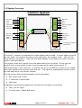
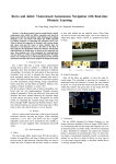
Volamp
User Manual
Page 1 of 25
Disclaimer
All information contained in this manual is believed to be accurate and reliable.
However, Volamp Ltd assumes no responsibility for its use. Since conditions of product
use are outside our control, we make no warranties express or implied in relation
thereto. We therefore cannot accept any liability in connection with any use of this
information.
This product is not intended for use in life support appliances, devices or systems where
a malfunction of the product can reasonably be expected to result in personal injury.
Use of any Volamp product in such applications is expressly prohibited.
Whilst every effort has been made to ensure that this document is correct, errors can
occur. If you find any errors or omissions please let us know, so that we can put them
right
Laser Safety
Invisible laser radiation. Class 1 lasers are used in this product for fibre optic
communications. The wavelength used is in the infra-red band so the light emitted
cannot be seen. Although the levels are low and are classified as safe under all
conditions of normal use, we recommend that users avoid looking directly into the
beam.
Trademarks
Camlinx™™ is a trade mark of Volamp Limited.
Opticalcon ® is a registered mark of Neutrik AG
Page 2 of 25
Volamp Camlinx™ User Manual
Contents
Disclaimer ........................................................................................................ 2
Volamp Camlinx User Manual............................................................................... 3
1 Overview.................................................................................................... 4
1.1 Pack Contents.......................................................................................... 4
1.2 System Overview...................................................................................... 5
1.3 Base Station Connections........................................................................... 6
1.4 Head Connections..................................................................................... 7
1.5 LCD Menus............................................................................................... 8
1.6 On Screen Display................................................................................... 10
2 Signals........................................................................................................ 12
2.1 Video..................................................................................................... 12
2.2 Trisync/Black and Burst............................................................................ 13
2.3 Talk back............................................................................................... 14
2.4 Serial Data............................................................................................. 15
2.4.1 Overview............................................................................................. 15
2.4.2 Tx and Rx............................................................................................ 15
2.4.3 Base Station........................................................................................ 15
2.4.4 Camera Head....................................................................................... 16
2.5 Tally...................................................................................................... 17
2.5.1 Overview............................................................................................. 17
2.5.2 Base Station........................................................................................ 18
2.5.3 Head Wiring......................................................................................... 18
2.5.4 Built In Tally Light................................................................................ 18
2.5.5 Tally Test............................................................................................ 18
3 Power system............................................................................................... 19
3.1 Introduction........................................................................................... 19
3.2 Using 48V power..................................................................................... 19
3.3 Using local power.................................................................................... 20
4 Fault finding................................................................................................. 21
4.1 Fibre levels............................................................................................. 21
4.2 Power system......................................................................................... 21
4.3 Can I use the Camlinx with the existing Fibre at my site?.............................. 21
4.4 Linking My Camera / Remote / Pan and Tilt / Intercom................................. 21
Page 3 of 25
1 Overview
The Camlinx™ is a system for connecting HD and SD SDI Cameras to a production area
using fibre optic cables. This manual describes how to use the Camlinx™.
1.1 Pack Contents
Every Camlinx™ system includes the parts listed below:
●
●
Camlinx™ Base Station, consisting of
○
Rack mount base station unit with mounting ears
○
Power cable suitable for your country
Camlinx™ head
○
Camlinx™ head unit
○
Rugged carrying case
Your dealer may have supplied:
●
Fibre optic cables
●
Interfacing cables to connect your Camlinx™ system to your other equipment
●
Other accessories
These are not detailed in this manual, so please contact your dealer if you require more
information.
Page 4 of 25
1.2 System Overview
Camlinx System
SDI Video
SDI Video
Tally
Tally
Sync
Talk back in
TDM
Encoder
TDM
Decoder
Sync
Talk back -phones
Serial (tx)
Serial rx
Serial (tx)
Serial rx
SDI Video
Talk back out
Serial rx
SDI Video
TDM
Decoder
TDM
Encoder
Serial rx
Talk back mic
Serial rx
Serial rx
Power
Supply
Power
Converter
Base Station
12V Supply for Camera
60 Watts max
Head
A Camlinx™ system is composed of a base station and a head. A single cable connects
the two ends. It contains two fibres and, optionally, two copper cores. Each of the
fibres carries information. One from the base station to the head, the other from the
head to the base station.
The copper cores carry power from the base station for the head. If they are not
present then a local power supply must be used at the head (see section 3).
TDM technology in the Camlinx™ is used to mix all of the different inputs into a single
fibre optic signal to be carried down the link. The signal is separated at the far end of
the link and fed to the various outputs.
The link carries the following signals in both directions:
●
SDI Video (HD or SD)
●
2 Channels of serial data
●
Talk back
In addition the following signals are carried from the base to the head:
●
Tally (on-air light)
●
Tri-level sync / Black and burst
Page 5 of 25
1.3 Base Station Connections
13
5
6
16
15
7
14
3
12
1
SDI Video output
2
SDI Video input
3
Serial 1 connector
4
Serial 2 connector
5
Button A (change page)
6
Button B (adjust setting)
7
LCD display
8
Tally input
9
110/230V AC input
9
3
11
4
8
1
10 Opticalcon® combined connector for power and fibre connections to the head
11 Talk back socket
12 48 volts output
13 Volume Knob
14 Sync input
15 48V power on indicators
16 Power meter
Page 6 of 25
2
1.4 Head Connections
8
1
2
9
4
10
7
3
12
14
5
6
1
SDI Video output
2
SDI Video input
3
PAG lock plate for connection to camera
4
PAG lock plate for connection to battery
5
Button A (change page)
6
Button B (adjust setting)
7
LCD display
8
Built in tally LED
9
External power input socket
10 Serial data socket
11 Headphones socket
12 Tally socket
13 Volume Knob
14 Sync output
Page 7 of 25
11
13
1.5 LCD Menus
The Camlinx™ menu system is the same on the base station as the head. It is
composed of an LCD screen and two buttons. The purpose of the system is to to enable
the user change settings and to
provide useful information
LCD Menu System
about the state the Camlinx™
system. An on-screen display
can be enabled on the video
output from the system. The
purpose of the OSD is to
provide useful information
about the state of the
Button A Button B
Camlinx™ system.
The LCD display system is
divided into pages. Each page
tells you about a particular
setting or parameter. The top
line of the LCD display (line 1)
tells you which page you are
on. The second line (line 2)
shows a value for that setting
or parameter. For example:
Button A
Button B
Vid in format
HD 1080 50i
In this case the top line tells you that you are looking at the input video format, and the
bottom line tells you what the format is (HD 1080 50fields/sec interlaced).
Button A is associated with the top line of the display, so pressing it cycles through the
display pages.
Button B is associated with the bottom line of the display, so pressing it changes the
value of the parameter when a setting is shown. If the page shows something which
cannot be set, button B has no effect.
The menu system can be set to consist of the 6 most commonly used pages, or an
extended set of 15 pages. The 'Extended menus' option switches between the two.
Each of the menu pages is described below:
Page
Details
FIBRE Rx
This gives a bar graph of the signal strength on the fibre
input1. See section 4.1 for more about fibre levels.
1Each block corresponds to approximately 26μW
Page 8 of 25
Remote FIBRE Rx
This gives bar graph of the fibre level being received at the
remote end, i.e. On the base station it shows the level being
received at the head, and on the head it shows the level
being received at the base station.
A good link is needed from the remote end for this function
to work, for example, for this function to work on the base
station, a good signal from the head is needed. If a signal
from the remote end cannot be decoded, and thus the fibre
level at the remote end cannot be read, 'Unknown' will be
displayed. See section 4.1 for more about fibre levels.
Vid in Format
The format of the SDI video input is shown. This is auto
detected, and cannot be set.
VID OUT FORMAT
The format of the SDI video output is shown. This is auto
detected, and cannot be set.
STATUS SCREEN
This controls the OSD (see section 1.6). The OSD can be set
to any of three modes:
- Always on
- Tally Safe
- Off
In the tally safe mode the OSD is on unless the tally is set.
This is to prevent the OSD from accidentally being shown in
the live mix.
EXTENDED MENUS
Yes – to make all menu pages available
No – for a limited set of menus
TALLY TEST/CALL
Holding button B in this mode will cause the tally light to
flash and the base station to click. Both ends will respond to
this function.
SERIAL 1 MODE
SERIAL 2 MODE
These pages switch the serial ports between RS232 and
RS422 mode. It should be noted that the setting affects the
local end only. For example, if this setting is used on the
base station to set serial port 1 mode to RS422, it will have
no effect on the setting for serial port 1 at the camera head.
For more information on the serial link see section 2.4
SERIAL STATE
This shows if any transitions have occurred on the serial links
in the last 2 seconds.
TALKBACK IN LVL
This shows a bar graph corresponding to the peak amplitude
of the audio input from the talk back socket
TALKBACK OUT LVL This shows a bar graph corresponding to the peak amplitude
of the audio output from the talk back socket, i.e. it shows
the level of audio being output. This is the audio which
comes into the system at the audio input at the remote end.
OSD SIZE
Two sizes are available for the OSD, big or small
DIAgNOSTICS
This shows technical information which can be useful to
Volamp for diagnosing fibre optic problems or misbehaviour
from equipment connected to the Camlinx™.
Page 9 of 25
1.6 On Screen Display
The on screen display gives information about the current state of the Camlinx™
system. Settings cannot be changed through the OSD.
System status hint
www.volamp.com
System OK
Fibre :
Vid In:
Sync :
Tally :
Talk :
Ser 1 :
Ser 2 :
Temp :
Remote end info
Local end info
THIS END
====
SD 625 50i
None
OFF
========
Rx
Medium
REMOTE END
=====
HD 1080/50i
==
Tx
Medium
The system status hint gives a summary of the current system status. It will tell you
if there is no video plugged in at the remote end, or if there are fibre optic problems.
Local end info tells you about the end nearest to you:
Fibre Rx shows a bar graph of the fibre receive level. Due to space limitations, one
block is shown here for every 2 on the LCD.
Vid In tells you what the format of the video connected to the video in socket is.
Talk tells you what the input talk level is.
Ser 1 and Ser 2 tell you whether transitions have been detected on the serial
interfaces. For more information see section 2.4
Temp tells you the temperature of the laser unit in the fibre optic transmitter. Very
high ambient temperatures can affect the laser and thus fibre optic performance.
Tally and sync are special cases. The signals only go from the base to the head. They
appear only in the local end column, with slightly different meanings on the base and
the head; as follows :
●
On the base: Tally:
tally input port
ON means that the tally has been triggered through the
Page 10 of 25
●
●
●
On the head: Tally: ON means that the tally has been triggered at the base
station, and that the tally output at the head is switched on.
On the base: Sync: 'Trisync / Black & Burst' means that a sync input has
been detected and is being transmitted to the head.
On the head: Sync: 'Trisync / Black & Burst' means that a sync signal is
being received from the base, and is being sent out to the sync out connector.
Remote end info tells you about the other end. i.e. at a base station it tells you about
the camera head, and vice versa. If there is no remote end connected, or there is a
problem with the fibre carrying information from the remote end, then this information
is not available, and 'Unknown' will be shown.
Page 11 of 25
2 Signals
2.1 Video
The Camlinx™ carries one SDI video stream in each direction. It does not support
analogue video of any type – composite, component, etc. It does not support multiple
channels of video in either direction.
A video signal connected to the base station's video in socket will appear at the head's
video out socket, and a video signal connected to the head's video in socket will appear
at the base station's video out socket.
The total delay of the system is less than one video line. No data rate reduction
techniques are used, this means that the video signal is not altered in any way by
passing it through the Camlinx™ system2. Ancillary data in the video signal will be
carried through unchanged by the Camlinx™.
A blue SD-SDI screen (PAL 50I) is given at the video output when no video is available.
No video is available when:
●
No video is connected to the remote end's video input
●
There is no fibre connection
Video Standard
Supported
SD-SDI 270MBit PAL
Yes
SD-SDI 270MBit NTSC
Yes
HD-SDI 1485MBit 1080 50i, 25p, 60i, 30p, 24p
Yes
HD-SDI 1483MBit 1080 59.9i, 29.9p, 23.9p
Yes
HD-SDI 1485MBit 720 60p
Yes
Composite
No
Component
No
3G-SDI
No
The two video streams – one each way – are completely independent, and do not need
to be of the same standard or locked to a related timing source.
When the video is first connected, or if the video standard or timing source changes,
the Camlinx™ may take a few seconds to correctly sync to it. During this time the
video signal may be disturbed.
2 If OSD is on, then the video picture will be altered
Page 12 of 25
2.2 Trisync/Black and Burst
This link is to allow gen-locking of cameras. A sync signal is connected to the sync
input on the base station it will come out of the sync output at the camera head. The
following types of signal can be carried:
●
Tri-level (HD) Sync
●
Black and burst3
The OSD shows whether a signal has been detected at the sync input. The blue screen
given out when no video is available will sync to a black and burst input on this socket.
Note that this link will not carry an analogue video picture.
3 The colour burst will be removed from the signal. The colour burst is not used on modern TV
Cameras.
Page 13 of 25
2.3 Talk back
The talk back system allows communication between a 3rd party intercom system at the
base station end (Clearcomm, RTS, etc.) and the camera man's headset at the head
end.
Camlinx Talk Back
System
5 pin XLR connectors are used at both
ends.
Connection to an intercom system is via
a 4-wire interface, with a signal level of
1V peak-to-peak / 0dBu.
3rd Party
Intercom
System
Line level
signals
Mic level
signal
Connection of a headset at the head end
is via a 5 pin XLR connector.
Headphone level
At the head end, a knob is provided to
signal
adjust the volume of the headphones.
At the base station a knob is provided
which adjusts the level of the signal
from the base station to the intercom
unit. This effectively sets the gain of
the camera operator's microphone.
Camlinx
Head
Camlinx
Base Station
Head end pin connections
Pin
Head End Function
Base Station Function
1
Microphone +
Audio in +
2
Microphone -
Audio in -
3
Ground/screen
Ground/screen
4
Headphones R
Audio out +
5
Headphones L
Audio out -
5 Pin XLR socket pin numbers:
5
1
2
3
4
Page 14 of 25
2.4 Serial Data
2.4.1 Overview
The Camlinx™ provides two identical full-duplex serial links. They can carry data at any data rate up
to 500KBit/second, and can be switched to operate according to the RS232 or RS422 standards.
Connection is via a single 12 pin HiRose connector on the camera head (which contains pins for
both links) and a 9-pin D-Type connector on the base station for each serial link. The base station
connectors feature auxiliary 12-volt power pins. These are for powering equipment connected to
the serial port, e.g. camera remote control units.
2.4.2 Tx and Rx
Pins named Rx are inputs into the camera head or base station, and Tx are outputs. This means
external equipment should drive into the Rx pins and be driven from the Tx pins. Rx on the camera
head drives Tx on the base station, and vice-versa.
Cam Linx
Camera Head
Cam Linx
Base Station
Data In
Rx
Rx
Data In
Data Out
Tx
Tx
Data Out
Data In
Rx
Rx
Data In
Data Out
Tx
Tx
Data Out
2.4.3 Base Station
Looking into socket:
5 4 3 2 1
9 8 7 6
1: Aux supply 0V
2: TX+ (RS232 / RS422)
3: RX+ (RS232 / RS422)
4: Aux supply 12V
5: Data Ground
6: No connection
7: TX+ (RS422 only)
8: RX- (RS422 only)
9: No connection
The load on the 12V power supply must not exceed 100mA (1.2 Watts) for each socket
Page 15 of 25
2.4.4 Camera Head
Looking into socket:
7
6
5
8
12
11
4
Serial A:
1: Rx+ (RS232/RS422)
2: Rx- (RS422 Only)
3: Gnd
4: Tx+ (RS232/RS422)
5: Tx- (RS422 Only)
3
9
10
1
2
Serial B:
7: Rx+ (RS232/RS422)
8: Rx- (RS422 Only)
9: Gnd
10: Tx+ (RS232/RS422)
11: Tx- (RS422 Only)
Towards tally socket
Page 16 of 25
2.5 Tally
2.5.1 Overview
Camlinx Tally System
C
D
Base Station
Head
Light
Detector
A
B
TDM Encoder
TDM Decoder
The tally system is used to provide an on-air indication at the camera head. The signal
is activated at the base station. Such an activation is indicated at the head by means
of:
1) A built in tally light
2) A contact closure for triggering external equipment
Activation at the base station is achieved by passing current between pins A and B.
This turns on a light inside the base station, which is detected in order to activate the
system. The built in tally light will illuminate at the head, and the connection between
C and D to be closed.
When the current passing between A and B stops then the built in tally light will
extinguish, and the connection between C and D will be opened.
Page 17 of 25
2.5.2 Base Station
The tally is activated via a 15-pin d-type socket on the rear of the base station. To
trigger the tally apply a voltage of between 5 and 12V DC between pins 5 and 134. A
5V supply is provided between pins 8 and 15 for convenience, but any supply can be
used to trigger the tally.
Looking into socket:
8 7 6 5 4 3 2 1
15 14 13 12 11 10 9
8: 5V
15: 0V
5: Opto-isolator pin A
13: Opto-isolator pin B
To trigger tally pass current between pins 5 and 13
2.5.3 Head Wiring
The contact closure for the tally is accessed via a 6 pin HiRose connector on the camera
head unit. A 5 volt power supply is provided for convenience.
Looking into socket:
(Clip fitting is on outside of socket
housing above pin 5, away from Coax).
4
3
5
2
6
1
Towards sync
connector
1: Relay pin C
2: Relay pin D
3: 0V
4: +5V
5 and 6: Not connected
Pins 1 and 2 are connected while tally is
triggered, otherwise they are open circuit.
2.5.4 Built In Tally Light
There is a built in tally light on the top of the camera head unit. It can be muted by
pressing it downwards.
2.5.5 Tally Test
To test the tally contact closures and built in tally light, the “Tally Test/Call” function
should be activated. It can be activated from either the base station or the camera
head.
4 Polarity is not important, i.e. it doesn't matter which way round positive and negative are
Page 18 of 25
3 Power system
3.1 Introduction
This section is concerned with the options for powering the Camlinx™ Head, and
powering Cameras through the Camlinx™ Head.
Cable Types
There are two basic types of cable which can be used to
connect the head to the base station:
1. Hybrid cable
2. Optical cable
Hybrid Cable:
Optical fibres to carry data
Copper cores for power
Optical Cable:
Optical fibres to carry data
There is a power supply in the base station which, when
hybrid cable is used, can power the head, and provide 60
watts of power to a camera connected to the head.
In standard optical cable there are no copper cores, so the
head must be powered by an alternative method. The
PAG lock on the head allows a battery to be used.
The 12V in socket allows an external power supply to be
used.
3.2 Using 48V power
The Camlinx™ power link operates at 48
volts DC. The power comes from 48 volt
supply in the base station, and is
converted down to 12 volts at the head.
Up to 60 watts (5 Amps) can be supplied
to a Camera, over a distance of up to
200 meters.
Base stations are optionally supplied with a redundant 48V power supply fitted. This is
indicated by a label saying 'Dual supply fitted' on the front panel.
There are two lights on the front panel to show that the 48 volt supplies are on. Both
will light up on units with a redundant supply fitted, and only one will illuminate
otherwise.
A load meter is provided.
Light
Power
Illuminates at >88 Watts. Overload
Illuminates at >60 Watts
Illuminates at >30 Watts
Illuminates at >1 Watt
The head uses 8 Watts, and can provide 60 Watts to the camera. This gives a total of
68 Watts. Some power will also be lost in the cabling, so the base station can deliver
up to 88 Watts of power.
Page 19 of 25
3.3 Using local power
Local power can be provided by a battery, through the PAG clip on the back of the
Camlinx™ Head, or it can be provided through the XLR connector.
The external power connector is a 4 pin male XLR.
Pin
Function
1
Ground
2
3
4
1
+12 to +18 Volts DC
4
The Camlinx™ head will operate on any supply voltage from 9.7 Volts to 18 Volts DC.
We recommend 12 Volts as a minimum because some cameras have problems
operating at lower voltages.
Pin 1 is connected internally to the chassis.
Don't get caught out by Voltage Drop on 12V Cabling!
Users should be mindful of potential problems when attempting to
carry power to camera over coper wires at 12 Volts, even over
relatively short distances.
For example, a camera and viewfinder combination can consume over
50 Watts. This leads to a current of 4 Amps. Because the initial
voltage is relatively low, the effect of voltage drop along the cable
becomes very significant.
Typically losses for a given length of cable at 12V (as a proportion of
the original voltage) will be equivalent to those of 19 times the length
of the same cable at 230V. That is to say a 25M camera lead of a
given core diameter will lose as much voltage (proportionally) as a
475M mains extension lead.
We therefore advise users to use the 48V link where possible.
Otherwise it is important to calculate out losses in any 12V system,
and not rely on intuition. Users should remember that cable losses
are proportional to load, and therefore that a cable which delivers a
perfect 12V before the load is applied may be providing a significantly
lower voltage once things are switched on.
Page 20 of 25
4 Fault finding
4.1 Ensuring good fibre connectivity
4.1.1 Introduction
It is of paramount importance that a good fibre optic link is established between the
head and the base station. Fibre-optic related problems can cause loss of connectivity in
either or both directions. Worst of all, fibre optic problems can cause intermittent errors
across all of the interfaces.
The aim of this section is to explain how you can tell a good link from a bad one, and
what you can do if you find link problems.
4.1.2 Things you need to know
Before we can look at how to check a link, it is important to understand what you are
looking for.
Why do I get different Fibre Rx Levels on different links?
Lasers are used as the light sources in the Camlinx™ system. Lasers are
inconsistent5, and differences between lasers are the main reason for different levels
observed on the received power bar graph. The photo diodes used on the fibre optic
input stage also have some inconsistency.
What Level should I look for?
The most important thing for a user to understand is that there is a little more to it
than just levels, and it is not possible to gauge the quality of the link from the
received fibre optic level alone.
There are two things which you need to look for when you are checking a link:
●
Continuity problems
●
Unexplained losses
Continuity problems are those which result in a total loss of signal. An unexplained loss
is a reduction of signal strength not consistent with the length of the link and the
number of interconnections.
So what kind of loss should I get?
Connector losses are low. The maximum for a Neutrik opticalcon Connector is 0.5dB.
This means that in the worst case the signal level should half for every 6 connectors.
Cable losses are also low, typically 0.2-0.4 dB per km.
A typical installation will have no more than 200M of cabling, and 2 or 3 connectors per
path. The total loss will then be just over 1dB in the worst case, usually less.
In terms of the Tx/Rx bar graphs, the worst loss we'd expect in any Camlinx™
installation would be one or two blocks.
4.1.3 Measuring Loss
In this example we will consider how to check a fibre link in a typical studio set up, but
the techniques used can be applied in any environment – studio, ENG, OB, etc. In this
5 This is why we guarantee only a minimum level (-10dBmW), and not a typical output power.
Page 21 of 25
set up the Camlinx™ base is connected to a patch panel. A long installed fibre runs from
said patch panel through to a patch panel in the studio. A cable then connects the
studio patch panel to the Camlinx™ head.
Typical Studio
Installation
Base Station
Control room
patching
Patch Bay
Traditionally fibre optic cables are tested with a
light source and light meter. A Camlinx™ unit
can act as both of these for you.
Link Test
Stage 1
The first step of testing is to check that the
Opticalcon® connector on the rear of the base
station is clean.
Base Station
Local
loopback
A loop-back connector6 is connected to the rear
of the base station. A Fibre Rx Level reading is
then read from the LCD on the front of the unit.
Patch Bay
Cables
installed in
building
Patch Bay
The fibre RX level here should match that shown
on the unit's factory test sheet (supplied with
the unit). If it does not then the connector
should be cleaned.
Patch Bay
Studio
cable
Head Unit
Link Test
Stage 2
The next steps (2,3,4) are to check the link one
leg at at time, isolating any problems that may
occur. If you find losses there are three usual
causes:
Head Unit
Link Test
Stage 3
Base Station
Base Station
Link Test
Stage 4
Link Test
Stage 5
3
Base Station
Base Station
Patch Bay
Local
loopback
Patch Bay
Patch Bay
Local
loopback
Patch Bay
Patch Bay
Patch Bay
Patch Bay
Patch Bay
Local
loopback
Head Unit
Head Unit
Loop back
box
Head Unit
1) Broken fibre
2) Dirt
3) Badly seated connectors
6 Available from your distributor, or as part of the Camlinx service kit
Page 22 of 25
Head Unit
The first can only be fixed by replacing the fibre. The second can be remedied cleaning
tools, available in our service kit. The last is more likely with LC type connectors (used
for installed fibre) than with Opticalcon®, and can often be fixed by removing and remating the connectors.
The last link in the chain is the connector on the head unit itself, and this can be
checked in the same way as the connector on the base station was checked in step 1.
As we are now using a another light source (that in the head rather than the base
station), the fibre rx level may be different. It should be checked against the test sheet
for the head.
Page 23 of 25
4.2 Power system
The Camlinx 48 volt power system is designed to solve the problems encountered when
using long cables to provide 12V power to Cameras. We recommend, therefore, that the
48V system is used wherever possible.
4.2.1 48 Volts system
The 48 volt system is designed to deliver 60 Watts (5 amps) at 12 vo
–
lts. Attempting to draw more power than this will cause the unit to cut out.
If you have problems, first check that the 48V supply is on. Next check the power
power meter.
–
–
–
If no lights are on – the head isn't connected. There is continuity problem, check
your cable and connectors.
If only the bottom light is on – only the head is powered, check your equipment is
switched on
If all lights are on, including the red light at the top – the power supply is overloaded
An overloaded power supply can be a result of
1) A short circuit – check your cables and connectors
2) Too much equipment being plugged into the head
3) Inrush problems.
Inrush problems occur because some equipment uses vastly more power at the
moment it is switched on than it does subsequently. If a number items are being
powered by the Camlinx head, it may be possible to run them all if they are switched on
in turn, rather than all at the same time.
4.2.2 12 Volts system
Be mindful of potential problems when attempting to carry power to camera over coper
wires at 12 Volts, even over relatively short distances. See section 3.3 for more
details.
4.2.3 Low Battery Warnings with 48V power
When operating on the 48Volt power system, the Camlinx head delivers about 12.9V
through the PAG plate to the camera. This is enough to power all modern camcorders.
A Camera cannot tell the difference between a Camlinx and a battery. If the threshold
for the low battery voltage warning on the Camera is set to above 12.9 Volts, then the
low battery warning will appear when the Camlinx is used.
To get rid of this warning, the warning threshold should be changed. For more
information on how to do this, contact your camera dealer or manufacturer.
It should be noted that camcorders work perfectly well while a low battery warning is
being displayed, and that most cameras don't cut out until well below 11 volts. The
Camlinx therefore has plenty of headroom.
Page 24 of 25
4.3 Can I use the Camlinx™ with the existing Fibre at my site?
Not all optical fibres are the same. Camlinx uses 9 µm single mode fibre. To put this in
context the diameter of human hair averages out at about 100 µm. This is the thinnest
type of fibre commonly in use. The benefit of such a small diameter is good bandwidth
performance.
Many buildings have multi mode fibre installed, which has a larger diameter (62.5µm).
This is often used for Ethernet equipment. Single and multi-mode fibre are not
compatible with one another. Other types of fibre commonly used are 50µm multimode, 85µm multi-mode, 200µm PCS (plastic clad silica) and plastic light pipe (used for
consumer AV equipment). None of these are compatible with Camlinx.
The Camlinx requires a direct optical connection from base to head, and the signal will
not pass through fibre optic switching equipment such as ethernet hubs, SMPTE video
switches, etc.
The maximum fibre length for the Camlinx is 2000m. If a greater reach is required,
please contact Volamp Ltd to discuss 15km and 80km options.
If your building has 9 µm single mode fibre installed, and the cable runs are less than
2km then you can use them with Camlinx.
4.4 Linking My Camera / Remote / Pan and Tilt / Intercom
Unfortunately we cannot provide free support to individual users for every type of
equipment that they may ever wish to connect with a Camlinx. However, where we do
have experience of interfacing to specific equipment, we will publish relevant details on
our web site in the form of application notes. These are also available through your
dealer, who will be happy to help with any interfacing problems you have.
Page 25 of 25