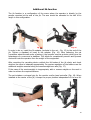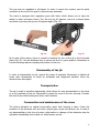
1
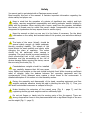
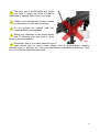
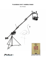
"FLAMINGO DUO" CAMERA CRANE
User Manual
Awarded at FVF 2015 Fair in the
Best Product – Video category!
Contents
Introduction
Technical specification
Crane elements
Safety
Setting up the crane
Assembly and installation
Disassembly
Transportation and storage
Conservation and maintenance
Warranty
2
3
3
4
6
7
11
11
12
12
Introduction
Thank you for choosing the Flamingo Duo camera crane. We put our
hearts into this project and construction so that you could receive a
functional and innovative product. The best personnel used their every effort
to make sure that you can operate it with nothing but satisfaction. Owing to
innovative and unprecedented solutions it will spread the wings of your
imagination and take your work to a completely different dimension.
Foton Accessories Team
wishes you a pleasant use
2
Technical data:
• Elevation height: max 370 cm,
• Arm length from crane rotating axis to camera rotating axis: max 280 cm,
• Crane transport length: 130 cm,
• Crane maximum length: 400 cm,
• Crane horizontal rotation: 360 degrees,
• Crane maximum load: 4 kg (registering device and accessories),
• Weight of jib without load: 10.5 kg,
• Cone Click mounting system of the crane to the tripod,
• Weight of STF tripod: 11.5 kg.
Technical information:
• All rotating elements are beared,
• The profile of jib is made of the highest quality materials with galvanized surface,
• The remaining elements of the crane are made of a hard aluminum alloy, machined
with laser technology which provides the highest precision,
• The sliding plates are made of Teflon® providing silent and easy movement of the
tool’s elements,
• The product is protected from corrosion by galvanized surfaces and powder paint
based on epoxy-synthetic resin.
Crane elements
•
•
•
•
•
•
•
•
•
•
•
•
Jib arm with an integrated rotating head (optional configuration),
STF tripod by Foton Accessories (max. height 150 cm),
4 x 2.5 kg weight plus 2 kg neck and nuts,
Holding arm with two photographic heads for monitor and Condor controller,
Wires: flexing and leveling,
Weights for precise balancing – 2 x 0.9 kg,
Grips with Velcro for cables,
1/4’’ and 3/8’’ knobs – for direct camera assembly,
Flexing wire mast,
Cover for the crane,
A bag for weights,
STF tripod cover.
Optional:
• Manfrotto 577 quick release system with a 501PL sliding plate,
• Foton Accessories quick release system,
• A 5 kg weight,
• An additional LCD arm.
3
Safety
You cannot wait to get started with a Flamingo camera crane?
Read carefully this part of the manual. It contains important information regarding the
device safety and proper use.
Keep in mind that the operation of a device of significant size, weight, and high
inertia, requires exceptional responsibility and taking particular caution relating to
safety with its operation. When working with a crane, apart from the operator, individuals
less aware of threats may be within the crane’s range. Irresponsible behavior can be
dangerous for bystanders and may expose them to serious injury.
Keep the manual so that you can use it in the future if necessary. For the latest
information on the safety and technical data of this product, see www.foton.kalisz.pl
website.
The basis of the crane (tripod), should be
spaced widely enough on stable substrate,
thereby providing stability. The wheels of the
tripod should be used carefully and slowly while
changing the place of operation. This action
should not be performed while camera is
operating. The crane should be moved carefully to
avoid uncontrolled heel or fall, which could put
bystanders and the surroundings at the risk of
serious damage. Before moving the device, secure
the arm using the knobs (Fig. 1).
Counterbalance weights should be installed
Fig. 1
very carefully, because their fall may cause
injury. Safety knob weights on the neck should be tightly fixed. While choosing a sufficient
mass of weights, keep the balance between the recording equipment and the
counterweight. Poorly balanced crane creates a direct threat to the environment. A
detailed description of this action is in the Assembly section.
During the assembly and disassembly of the head, recording equipment and free
weights particular attention should be paid to blocking the arm (Fig. 1). Thus, you
will avoid uncontrolled movement or collapse of the jib.
Knobs blocking the extension of the crane’s arms (Fig. 6 - page 7), and the
registering device grip and weights must be sufficiently tight.
Do not put fingers or hands into the moving parts of the jib support. There are
strong compressive forces in this place associated with a significant length of the arm
and its weight (Fig. 2 - page 5).
4
The crane has a counterweight arm at the
rear. Lack of control can cause a threat to
bystanders or damage items found in its range.
Children and unauthorized persons should
not be allowed to work with the device.
Do not exceed the nominal load limit
recommended by manufacturer.
Making any alterations in the device causes
loss of warranty and may pose a direct
threat to the surroundings.
Fig. 2
Remember! Due to the metal materials from which the camera crane was made, in
close contact with the device under voltage, such as lighting lamps, dangling
electrical wires, or lightning, etc., the crane may become a conductor of electricity. There
is a risk of electric shock and even death.
5
Setting up the crane
1. The tripod should be spaced widely enough,
so that it could stand on its legs instead of wheels.
2. The jib is installed on the tripod in vertical
position (at the right angle to the tripod’s axis).
3. The tilt brakes should be blocked.
4. Extend the two top profiles of the jib.
5. Mount the neck with the first 2.5 kg weight.
6. Extend the third profile.
7. Mount another 2.5 kg weight.
8. Install the flexing wire.
9. Install the leveling wire.
10. Install the Koliber head.
11. Mount the next 2.5 kg weight.
12. Install the camera.
13. Balance with the next weight.
14. Use the sliding weight to balance precisely.
6
Detailed description of assembly and installation
STF tripod – basic information:
Load
capacity
provided
by
the
•
manufacturer is 40 kg max.,
Spacing of legs from the tripod axis is 75
•
cm min.,
The tripod contains a spreader which
•
secures the legs from further spacing in the
event of pressure on the tripod.
The tripod (Fig. 3) should be set up and secured
from accidental collapse. The column should be
extended according to one’s needs, blocked with
Fig. 3
the pin and secured with a knob.
The jib is installed on the tripod by joining them with the Cone Click system. Make sure
that the cones of the quick connector are properly fitted, then block them by tightening
the knob (Fig. 4 and 5).
Attention! The knob must be tightly fixed without any clearance between elements.
Fig. 4
Fig. 5
Next, untighten the four knobs at the top and two
knobs at the bottom (Fig. 6) and extend the
elements of the device as far as they will go (two
arms and a moveable grip of the head).
The extended jib should be secured by tightening
all the above-mentioned knobs back.
In order to calculate the appropriate mass of
counterweights, multiply the complete weight of
the registering device with the mounted
accessories by the value of about 3.
Fig. 6
7
Example: a complete registering device weighing at 3 kg together with the head is
multiplied by 3, thus, a counterweight of about 9 kg should be applied (considering the 2
kg weight of the neck).
Before mounting the weights, the top part of the grip should be untightened, the neck
should be placed on the lower part, and next the top element should be placed back and
tightened fast with the blocking knob.
Assembling the weights should be matched with the assembly of the head and the
registering device. The installation should be conducted with the jig remaining as close to
the point of equilibrium as possible (see page 6).
Further, install the flexing wire. In order to do so, mount a mast on the axis of the jib
(Fig. 7).
Fig. 7
Fig. 8
The flexing line of the crane in the front part is placed on a knob which block the position
of the last segment of the arm (Fig. 8), and in the rear part it is placed on the knob which
blocks the neck of the counterweight (Fig. 9).
In order to acquire the proper flex, use the "click-type" tensioner in the central part of the
wire (Fig. 10).
Fig. 9
Fig. 10
8
Before installing the Koliber rotating head, a leveling wire must be mounted (Fig. 11
and 12).
The element that joins the jib and the head should – independent of the tilt angle of the
jib – remain in the horizontal position. The tilt is regulated by a Roman screw placed on
the leveling wire.
Fig. 12
Fig. 11
The operating part of the jib may be shortened by half. In order to do so, slide back the
telescopic elements of the jib and place the end of the wire on the wheel (Fig. 11), where
the “end-eye” of the wire had been installed earlier. In this version, the flexing wire is not
used.
Mounting the Koliber head
In order to mount the head on the camera crane securely and properly, slide it
simultaneously into the two quick connector sockets. Next, secure the head by tightening
the blocking knobs on the side. Further steps of installing the registering device are set
forth in a separate manual for the Koliber head.
Fig. 13
Fig. 14
9
Additional Jib function
The jib function is a configuration of the crane where the operator is directly by the
camera mounted at the end of the jib. The arm should be extended to the half of its
length in this configuration.
Fig. 15
Fig. 16
In order to do so, install the Jib adapter (included in the set – Fig. 15) to the end of the
jib. Tighten a standard oil head to the adapter (Fig. 16). After balancing the set
(remember about the safe order of actions), the operator receives a device which joins the
advantages of a crane and a stabilizer. This allows for exceptionally smooth and dynamic
shots and rests the operator from the weight of the equipment.
After mounting the recording device unblock the tilt brakes of the jib slowly and check
whether the crane is balanced appropriately. For precise regulation of the balance use the
additional weights mounted along the counterweight arm axis (Fig. 17).
If the mass of the counterweight is inappropriate, add or remove weights on the neck in
order to achieve the required balance.
The set includes a universal grip for the monitor and/or head controller (Fig. 18). When
installed at the center of the jib, it keeps the proper position independent of the arm tilt.
Fig. 17
Fig. 18
10
The grip may be regulated in all planes. In order to mount the monitor, use the quick
connector at the end of the grip for safe and easy assembly.
The crane is equipped with regulation grips with Velcro which allows you to keep the
cables in order and secure them. Turn the grip by 90 degrees, move to a desired place
and block by turning the grip by 90 degrees again (Fig. 19).
Fig. 19
Fig. 20
At the side of the device, there is a knob for blocking the turn of the jib in the horizontal
plane (Fig. 20). Use the blockage only to secure the arm in a given position. Remember to
free the blockage before changing the position of the arm.
Disassembly of the jib
In order to disassemble the jib, reverse the order of assembly. Remember to tighten all
knobs after disassembly to avoid an accidental and dangerous situation when the
elements can draw apart.
Transportation
The set is small in size after disassembly, which allows for easy transportation in the trunk
or at the backseat of the car. Remember to place the crane in the car securely. Consider
the inert forces while braking and other road incidents.
Conservation and maintenance of the crane
The device demands no special conservation apart from keeping it clean. Check the
condition of the elements such as knobs, weight grips, screw connections, etc. In case of
any abnormalities in the form of cracks, deformation or damage of the elements stop the
operation immediately and contact our maintenance service.
11
Warranty
The products of Foton Accessories are covered by a standard warranty for a period of 36
months from the date of purchase. The warranty covers all defects in material and
construction and is associated with the repair, or if the repair proves to be impossible, a
replacement of the product with a new one. Warranty does not cover damage or defects
of the product arising as a result of improper use.
Warranty also does not cover flooding, moisture, mechanical damage such as dents,
scratches, indentations, independent and unauthorized repairs or modifications.
Any signs of standard use of the product are not subject to warranty conditions.
During the period of warranty the purchaser shall provide defective product to the
manufacturer or authorized dealer after previous arrangements (contact details are
included in the footer of this manual), along with a photocopy of proof of purchase
(invoice, bill, receipt). The manufacturer also carries out repair and spare parts sale after
the warranty period.
We wish you a pleasant use!
Foton Accessories Team
Manufacturer:
Foton Accessories
This manual can be downloaded at:
www.fotonexport.com
Made in Poland
Tel.: +48 62 764 46 63
Fax: +48 62 764 46 22
E-Mail: [email protected]
12