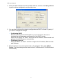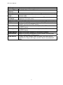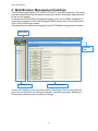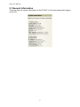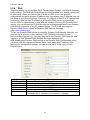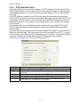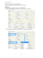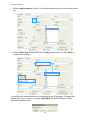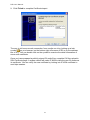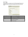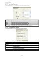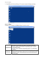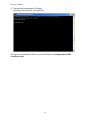
1
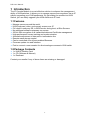
User Manual
KVM IP Console Module Card
DIP-101
Rev. 1.0
2010.05.31
Table of Contents
1 INTRODUCTION ......................................................................................................................1 1.1 FEATURES ..........................................................................................................................1 1.2 PACKAGE CONTENTS..........................................................................................................1 2 HARDWARE INSTALLATION.....................................................................................................2 3 GETTING STARTED ..................................................................................................................3 3.1 INITIAL CONFIGURATION....................................................................................................3 3.2 PREREQUISITES ..................................................................................................................6 3.3 INSTALLING JVM ON CLIENT SYSTEM..................................................................................6 4 LOGIN TO THE IP KVM SWITCH ...............................................................................................7 5 WEB BROWSER MANAGEMENT INTERFACE ............................................................................8 5.1 GENERAL INFORMATION....................................................................................................9 5.2 CONFIGURATION .............................................................................................................10 5.2.1 ALERTS.............................................................................................................................11 5.2.2 NETWORK........................................................................................................................12 5.2.3 IP FILTER ..........................................................................................................................12 5.2.4 DNS .................................................................................................................................15 5.2.5 NTP (DATE AND TIME)......................................................................................................16 5.2.6 NFS (NETWORK FILE SYSTEM)...........................................................................................17 5.2.7 IMAGE QUALITY...............................................................................................................17 5.2.8 REMOTE BUTTON KEY ......................................................................................................17 5.2.9 SERIAL OVER LAN .............................................................................................................22 5.2.10 USERS..........................................................................................................................23 5.2.11 SSL CERTIFICATE ..........................................................................................................23 5.2.12 LDAP ...........................................................................................................................29 5.2.13 TERMINAL CONSOLE....................................................................................................30 5.2.14 NETWORK PORT SETTING ............................................................................................30 5.2.15 SNMP ..........................................................................................................................31 5.3 REMOTE CONTROL...........................................................................................................32 DIP-101 Manual
5.3.1 CONSOLE REDIRECTION....................................................................................................32 5.3.1.1 VIDEO..........................................................................................................................33 5.3.1.2 KEYBOARD ..................................................................................................................34 5.3.1.3 MOUSE........................................................................................................................35 5.3.1.4 OPTIONS .....................................................................................................................35 5.3.1.5 DEVICE (VIRTUAL MEDIA REDIRECTION).......................................................................36 5.3.1.6 KEYS (REMOTE BUTTON KEY) .......................................................................................38 5.3.1.7 EXCLUSIVE...................................................................................................................39 5.3.1.8 SOFT KEYBOARD..........................................................................................................39 5.3.2 TERMINAL CONSOLE ........................................................................................................40 5.4 SERIAL POWER CONTROL .................................................................................................41 5.5 MAINTENANCE ................................................................................................................43 5.5.1 FIRMWARE UPDATE.........................................................................................................43 5.5.2 PS/2 FIRMWARE UPDATE.................................................................................................45 5.6 SYSTEM LOG ....................................................................................................................48 5.7 RESET IP KVM ..................................................................................................................48 6 TROUBLESHOOTING .............................................................................................................49 APPENDIX A: SPECIFICATIONS........................................................................................................51 APPENDIX B: CREATING CA FILES ...................................................................................................52 APPENDIX C: CERTIFICATIONS........................................................................................................58 ii DIP-101 Manual
1 Introduction
The IP Console Module is a cost-effective solution to enhance the management
ability of KVM switches. It allows you to manage servers from anywhere via an IP
without upgrading your KVM equipments. By just sliding the module into KVM
Switch, you can easily upgrade your KVM switches to IP level.
1.1 Features
♦
♦
♦
♦
♦
♦
♦
♦
♦
♦
♦
Manage servers around the world.
KVM (keyboard, video, and mouse) access over IP
Full control under any OS, in BIOS mode, during boot, at Blue Screens
No additional software necessary on servers
256 bit SSL encryption of all transmitted data and Certificate management
High-performance mouse tracking and synchronization
Automatic adjustment of data rate to transmission line
Remote mass storage control
Can be controlled over all java-enabled Browsers
Firmware update via web interface
Port to connect a user console for direct analogous access to KVM switch
1.2 Package Contents
♦ 1 x KVM IP Module Card
♦ 1 x CD (Software & Manual)
♦ 1 x Desiccant
Contact your reseller if any of above items are missing or damaged.
1 DIP-101 Manual
2 Hardware Installation
IP Console Module
Zoom-in
LAN Port Serial Port
Mini-USB Port
Follow the steps below to install the module in your KVM Switch:
1. Power off your KVM switch.
2. Remove the screw to open the back cover of module slot.
3. Slide the module card into the slot and secure it to KVM switch.
4. (Optional) Connect the type A connector of USB A-mini B cable to the host
computer, while using remote mass storage control.
5. Connect the Ethernet cable to LAN port or the modem to serial port, depending
on how you want to access IP KVM switch.
6. Power on your KVM switch.
Congratulations! You have transformed your KVM switch into an IP KVM switch. The
figure below shows the connections of IP KVM switch application.
2 DIP-101 Manual
3 Getting Started
3.1 Initial Configuration
In addition to VT100 interface, we also provide a Network Setup Software tool (IP
Setup Utility) for the network settings to the IP KVM. The factory default settings are:
Parameter
DHCP
IP Address
Subnet Mask
Value
Disable
192.168.0.1
255.255.255.0
The IP Setup Utility is useful when setting up the network configuration (IP address,
Subnet mask, DHCP, etc). IpSetup tool can be found in the CD-ROM shipped with
package. You can view or change the network settings via this utility.
Follow the description below to setup your IP KVM switch.
1. Connect the IP KVM switch to your computer via local network (Ethernet cable).
2. Run the setup tool IpSetup.exe from CD-ROM. A window will display as below.
3. The MAC address of IP KVM switch is displayed on Device MAC address field.
3 DIP-101 Manual
4. Select the MAC address from Device MAC address and then click Query Device
to get the device configuration on the right pane.
5. You can then configure the network configuration as DHCP or fixed IP (static). If
you want to change the settings.
♦ Configuring DHCP
Before connecting the IP KVM switch to your local network, be sure to
complete the corresponding configuration of the DHCP server.
Select the “IP Mode” as “DHCP” and obtain the IP address, Subnet mask and
gateway from DHCP server automatically.
♦ Configuring Fixed IP
Select “IP Mode” as “Static” and then configure the IP address, Subnet mask
and Gateway.
6. Enter the Super user name & password on the left pane. Then click Update
Device. The new settings will be saved to the IP KVM and the IP KVM will reboot
automatically.
4 DIP-101 Manual
Device
The device type of the module card.
Device Type
The MAC address of the IP Module card.
Device MAC
Address
Authentication
Enter the login name of the super user. The default value is “root”
Super User
(in lower case).
Login
Enter the login password for the super user. The default value is
Super User
“superuser” (in lower case).
Password
Device Configuration
Select the IP configuration mode as static (fixed IP address), dhcp
IP Mode
Configure the IP address manually for a fixed IP or obtain a
IP Address
dynamic one from the DHCP server.
Configure the subnet mask manually for a fixed IP or obtain it from
Subnet Mask
the DHCP server.
Configure the default router manually for a fixed IP or obtain it from
Gateway
the DHCP server.
Search Device Search for the MAC address of connecting IP Module.
Display the current configuration (some firmware versions may
Query Device
require authentication for this action).
To apply the new settings, enter the super user name and its
Setup Device
password for “Super user login” and the “Super user password”
fields.
5 DIP-101 Manual
3.2 Prerequisites
In order to access the remote host system using a securely encrypted connection,
you need a browser that supports the HTTPS protocol. Strong security is only
assured by using a key length of 128-Bit. Some of the old browsers do not have a
strong 128-bit encryption algorithm. You can access the IP KVM switch using the
insecure HTTP protocol, or using the encrypted HTTPS protocol. Whenever
possible, use HTTPS.
For Windows Internet explorer users, to check to encryption algorithm, open the
“About” option from “Help” menu to read the key length that is currently activated.
Newer web browsers generally support strong encryption on default.
3.3 Installing JVM on Client System
IP KVM switch was accessed using a standard JAVA enabled web browser. You must
install Sun JVM 1.6 or above in your client system.
Note: At a minimum you must have Internet Explorer 6.0 (or above) or Firefox 1.0
(or above) installed on your client computer.
6 DIP-101 Manual
4 Login to the IP KVM Switch
Launch your web browser. The address used might be an IP address or a domain
name if you have given your IP KVM a symbolic name in the DNS.
Enter the following address in the URL field of your browser when establishing an
unsecured connection:
http://<IP address of IP KVM switch>
Enter the following address in the URL field of your browser when using a secure
connection:
https://<IP address of IP KVM switch>
This will lead you to the IP KVM login page as shown below. When connecting to the
IP KVM, the IP KVM system (web server) will prompt you to enter the user name and
password in order to access to the system.
The IP KVM switch is built-in with a super user that has all permissions to administrate
your IP KVM switch. The account (username and password) for super user are:
Username
Password
root (factory default)
superuser (default)
There are two levels of access privileges:
User Name
Default Password Access Privileges
root
superuser
full access
(user define)
(user define)
limited access
Warning!!! It is recommended that changing the superuser’s password
immediately after you login to the IP KVM for the first time. Otherwise, the system
may face security risks and unauthorized access to the IP KVM and the host
system.
The administrator can add or remove a user easily via the web pages of System
administration.
In order to protect IP KVM from unauthorized user access, a session access timeout
of 300 seconds is fired or restarted each time the web page configuration is initiated.
You will be redirected to login webpage and asked to do account authentication
again. The session timeout helps you to prevent from those who do not have access
privilege to modify system configuration. In other words, if you leave the web
browser idle for more than 300 seconds the login session will time out and thus
terminate the session to prevent others from accessing to the IP KVM.
7 DIP-101 Manual
5 Web Browser Management Interface
The IP KVM supports both HTTP and HTTPS (HTTP over SSL) protocols. The users
must be authenticated by the system by using the correct user name and password
to log into the system.
To access the IP KVM Web management pages, enter the IP KVM’s IP address or
resolvable hostname into the web browser’s URL/Location field. This will direct the
user to the IP KVM login screen.
The figure below shows the homepage of the IP KVM Web management interface.
Menu Bar
Function
Title
Function List
Section Information
A menu bar displays on the top of the screen. Selecting an item on the menu bar
opens a tree view of all the functions available under each grouping. Selecting a
function item will allow you to modify its settings.
8 DIP-101 Manual
5.1 General Information
This page lists the system information of the IP KVM. It is the homepage after logging
to the unit.
9 DIP-101 Manual
5.2 Configuration
This page lists the options of configuration. Choose the item you would like to
configure.
10 DIP-101 Manual
5.2.1
Alerts
This page allows you to configure the system alert destinations.
To configure a new alert, select the entry and click Modify button. The configuration
page will display as below.
Item
Alert Type
Destination IP
Engine ID
Description
Select the type of the alert.
Enter the IP address of the system that alerts will be sent.
Enter the unique identifier of a SNMP engine.
11 DIP-101 Manual
5.2.2
Network
This page allows you to configure the network settings. The IP KVM requires a valid
IP address to operate within the user’s network. If the IP address is not readily
available, contact the system administrator to obtain a valid IP address for the IP KVM.
Please note that the IP KVM requires a unique IP address to connect to the user’s
network.
There are two types of IP assignments user can choose from:
♦ Static IP
♦ DHCP (Dynamic Host Configuration Protocol)
The IP KVM is initially defaulted to Static IP mode, with a static IP address of
192.168.0.1. The IP configuration setting will not take effect until clicking the Save
button.
5.2.3
IP Filter
This page allows you to configure IP filter settings. The IP filter keeps unauthorized
hosts from accessing to the IP KVM by specifying IP filter rules. It is important to
correctly understand what an IP filter is. Otherwise, you might get unexpected results
against your original plan.
12 DIP-101 Manual
The IP address/Mask specifies the host range by entering host IP address followed
by / and subnet mask. The host IP addresses will be filtered are based on the rules
defined. The table below gives examples of IP address/Mask settings.
Specified Host Range
Any host
192.168.1.120
192.168.1.1 ~ 192.168.1.254
192.168.0.1 ~ 192.168.255.254
192.168.1.1 ~ 192.168.1.126
192.168.1.129 ~ 192.168.1.254
Item
IP filtering
enable/disable
IP address/Mask
Port1[:Port2]
Chain Rule
Host IP Address
0.0.0.0
192.168.1.120
192.168.1.0
192.168.0.0
192.168.1.0
192.168.1.128
Description
Select to enable or disable IP filtering.
Enter the IP address and subnet mask for the rule.
Enter the port number or port range of the IP KVM which hosts
try to access to.
Select if the access from the hosts will be allowed (ACCEPT) or
denied (DROP).
13 Subnet Mask
0.0.0.0
255.255.255.255
255.255.255.0
255.255.0.0
255.255.255.128
255.255.255.128
DIP-101 Manual
When the IP KVM receives a TCP packet, it will process the packet with the chain rule
depicted below. The packet will be matched with the chain rule 1 first. The system will
take action directly if the packet meets the chain rule 1, otherwise, go to chain rule 2.
TCP Packet
Rule 1
Yes
Action
Yes
Action
Yes
Action
Yes
Action
Yes
Action
No
Rule 2
No
Rule 3
No
Rule 4
No
Default Rule
You can add a new IP filtering rule by setting the properties and then click the Add
button. To delete an existing rule, just click the Remove button next the rule.
In the example above, the rules applied in the following order:
#1. Those hosts belonging to subnet 192.168.123.x are allowed to access to the
IP KVM (through http port 80).
#2. Those hosts belonging to subnet 192.168.1.x are allowed to access to the
IP KVM (through http port 80).
#3. All hosts are allowed to access to the IP KVM (through http port 80).
After these three rules applied, only the hosts which belong to the subnet 192.168.1.x
or 192.168.123.x can access to the IP KVM (through http port 80).
14 DIP-101 Manual
5.2.4
DNS
This page allows you to configure DNS (Domain Name System) and DDNS (Dynamic
DNS) settings. The DNS is the Internet service that translates your domain names into
IP addresses. When you connect the IP KVM to a DSL line or use a DHCP
configuration and get a dynamic IP address from the network, the IP address may not
the same as previous connection. Therefore, it is difficult to know if an IP address has
changed or what the new IP address is. A Dynamic DNS service is provided by
various ISPs or organizations to deal with this situation. By using the Dynamic DNS
service, you can access the IP KVM through the hostname registered in the Dynamic
DNS Server regardless of any IP address change. The IP KVM only supports
Dynamic DNS service offered at Dynamic DNS Network Services
(http://www.dyndns.org).
To use the Dynamic DNS service provided by Dynamic DNS Network Services, you
must set up an account in their Members' NIC (Network Information Center http://members.dyndns.org). You may then add a new Dynamic DNS Host link after
logging in to their Dynamic DNS Network Services Members NIC.
After enabling the Dynamic DNS service in the Dynamic DNS Configuration menu,
you must enter the registered Domain Name, User Name and Password. After
applying the configuration change, you can access the IP KVM using only the
Domain Name.
Item
DNS Server 1/2
Dynamic DNS
Domain Name
User Name
Password
Interval Time
Description
Enter the IP address of DNS server(s).
Select to enable or disable DDNS.
Enter the domain name of your DDNS account.
Enter the user name of your DDNS account.
Enter the password of your DDNS account.
Enter the time interval after which DDNS server should check
and update the IP address of your server if changed.
15 DIP-101 Manual
5.2.5
NTP (Date and Time)
This page allows you to manually configure the NTP (Network Time Protocol) server.
The IP KVM maintains current date and time information and these are backed up by
internal battery power. You can set the time and date either by NTP or specify them
manually.
If the NTP feature is enabled, the IP KVM will obtain the date and time information
from the NTP server at each reboot, then automatically align with the NTP server time
every hour. If the NTP server is set to 0.0.0.0, the IP KVM will automatically use the
default NTP servers. In this case, the IP KVM should be connected from the network
to the Internet.
The second method is to set date and time manually without using the NTP server.
This will allow the date and time information to be kept maintained by the internal
battery backup.
You must also specify the time zone, Greenwich Mean Time (GMT), if you use NTP to
obtain the time and date. This time is also known as Universal Time (UTC). You also
need to set the time offset from UTC depending on your location. You system will then
be able to calculate the correct date and time. Please refer to the website
http://time_zone.tripod.com for the time offset from UTC.
Item
Use NTP
NTP Server
Date
Time
UTC Offset
Description
Select to enable or disable NTP Server.
Enter the IP address of a NTP server or enter 0.0.0.0 for auto
detection.
Enter the date manually if the Use NTP function is disabled.
Enter the time manually if the Use NTP function is disabled.
Select the UTC (Coordinated Universal Time) offset from the
drop-down list according to your location.
16 DIP-101 Manual
5.2.6
NFS (Network File System)
This page allows you to configure the NFS function. The IP KVM supports NFS
(Network File System) service for system or port data logging.
Item
NFS Service
NFS Server Name
Mounting Path on NFS Server
NFS File Name
5.2.7
Description
Select to enable or disable NFS Service.
Enter the IP address of NFS server.
Enter the mounting path of NFS server.
Enter the file name and extension name of NFS file.
Image Quality
This page shows the video image quality level.
5.2.8
Remote Button Key
This page allows you to configure the remote button keys. Remote button keys are
used to simulate keystrokes on the remote console and send the concatenated key
codes to the remote host computer. This function is to prevent the key code from
being captured or blocked by the local operating system or the downstream KVM
switch. Typical examples are “Ctrl+Alt+Delete” on Windows and DOS or
“Ctrl+Backspace” on Unix or Unix-like OS for terminating the X-Server.
17 DIP-101 Manual
Multiple key codes can be concatenated.
Here are examples for configure the remote button key.
Example 1:
When you want to define a keystroke of L-Shift + F3:
1. Enter the Key Name that stands for the key strokes combination.
2. Select choice key 1: Select L-SHIFT from the Key 1 drop-down list.
18 DIP-101 Manual
3. Select conjunction key: Select “+” to be the conjunction key from the drop-down
list.
4. Select choice key 2: Select F3 from the Key 2 drop-down list. Click Save to
complete the setting.
You will see the created button key is showing on top of the page. To trigger this
remote button key, you have to press Light Shift key and F3 function key on
keyboard simultaneously.
19 DIP-101 Manual
Example 2:
When you want to define a keystroke of R-Shift - F3:
1. Enter the Key Name that stands for the key strokes combination.
2. Select choice key 1: Select R-SHIFT from the Key 1 drop-down list.
20 DIP-101 Manual
3. Select conjunction key: Select “-“ to be the conjunction key from the drop-down
list.
4. Select choice key 2: Select F3 from the Key 2 drop-down list. Click Save to
complete the setting.
You will see the created button key is showing on top of the page. To trigger this
remote button key, you have to press Right Shift key and release, then press F3
function key on keyboard.
21 DIP-101 Manual
Open the Remote KVM Console (see the section Remote Control), you will see the
button key L-Shift + F3 and R-Shift - F3 are shown on the drop-down menu. Clicking
on the button key will send the key codes to the remote host computer.
5.2.9
Serial over LAN
This page allows you to configure the Serial port settings.
Item
Description
Operation Mode
Select the operation mode from drop-down list.
Serial Power Mode Select the serial power mode to be RS232 or RS485.
The Serial Power Controller (SPC) is a family of intelligent power distribution units that
enables remote power control of servers and network appliances. When used in
conjunction with IP KVM, the SPC provides comprehensive management capabilities
and quick problem resolution by integrating console access with power control into a
single interface. The SPC supports both RS232 and RS485 interfaces and can be
located up to 1.2km away from the controlling master, and has the Daisy chain
capability in RS485 mode. Refer to section “Serial Power Control” for more details
about Serial Power application.
22 DIP-101 Manual
5.2.10 Users
Administrator can create as many as 10 user accounts for controlling the IP KVM.
5.2.11 SSL Certificate
This page allows you to configure SSL (Secure Sockets Layer) certificate. A SSL
certificate is a digital identification which contains information to attest that certificate
belongs to specific person, organization, server or other entity noted in the certificate.
IP KVM supports secure HTTP (with the prefix https://) to make configuration change
via web page. The server side SSL certificate identify IP KVM server itself so that you
can rely on the certificate and make the configuration change confidently.
IP KVM is capable of uploading customized certificate files to web server. The
certificate file suite includes three files. All three certificate files must be uploaded to
complete certificate upgrade. The file upload interface is similar to firmware upgrade.
Once all certificate files are uploaded, you have to initiate a reboot command
manually to make the new certificate effective.
Browse prepared CA files (follow procedure in Appendix B to prepare CA files with
same assigned filenames) and upload those files to IP KVM. Please double check
each files before uploading. A false CA file suite may disable secure HTTP function.
23 DIP-101 Manual
1. Click Browse to select the rootca.pem as the Default Certificate and click
Upload.
2. Click Browse to select the rootca.key.pem as the Default Private Key and click
Upload.
3. Click OK to reboot the IP KVM.
4. You can then check the Certificates from Windows IE browser ToolsÆInternet
OptionsÆContentsÆCertificatesÆView.
24 DIP-101 Manual
5. Click Install Certificate to install the Certificate.
6. Click Next to import the Certificate.
25 DIP-101 Manual
7. Specify t he file you want to import and click Next to import the Certificate.
8. Select a location to save the Certificate and click Next.
26 DIP-101 Manual
9. Click Finish to complete Certificate import.
The way to tell a secure web connection from unsafe one is by looking up a lock
symbol ( ) on your browser (on the bottom-right of browser of IE6 or on the address
bar of IE7). You can double click on the symbol to examine the detail information of
server side certificate.
Once you have prepared a publicly signed CA suite files, complete CA files upload in
SSL Certificate page. A system reboot will make IP KVM to take the new CA suites as
its certificate. You can verify the new certificate by looking into IP KVM certificate in
next https session.
27 DIP-101 Manual
The following example demonstrates a publicly signed certificate and information
registered to certificate authority (VeriSign).
28 DIP-101 Manual
5.2.12 LDAP
This page helps you to download user list of LDAP (Lightweight Directory Access
Protocol) server then create the user account from this list directly. LDAP is an
application protocol for querying and modifying directory services running over
TCP/IP.
Item
Enable LDAP Authentication
Port
IP Address
Bind Password
Bind DN
Searchbase
Description
Check to enable LDAP authentication.
Enter the port number of LDAP Server.
Enter the IP address of LDAP Server.
Enter the password for authentication.
Enter the DN (Distinguished Name) for the server
uses to bind to the directory.
Define the location in the directory from which the
LDAP search begins
29 DIP-101 Manual
5.2.13 Terminal Console
This page allows you to configure the terminal console setting.
Item
Band Rate
Data
Parity
Stop
Flow Control
Description
Select the bps (bits per second) from the drop-down list.
Select the data bits from the drop-down list.
Select the parity type from the drop-down list.
Select the stop bits from the drop-down list.
Select the flow control method from the drop-down list.
5.2.14 Network Port Setting
This page allows you to configure network port settings.
Item
Description
Enable Terminal Check to enable terminal access.
Access
HTTP Port
Enter the HTTP (Hypertext Transfer Protocol) port number for
network settings.
HTTPS Port
Enter the HTTPS (Hypertext Transfer Protocol Secure) port
number for network settings.
SSH Port
Enter the SSH (Secure Shell) port number for network settings.
30 DIP-101 Manual
5.2.15 SNMP
This page allows you to configure SNMP (Simple Network Management Protocol)
settings.
Item
Enable SNMPv1/v2
Access Level
Community String
Enable SNMPv3
User Account
User Access
Authentication
Protocol
Authentication
Passphrase
Privacy Protocol
Privacy Passphrase
Description
Check to enable SNMPv1/v2.
Select the access level to be read-and-write or read only.
Enter the community string (password) for the access.
Check to enable SNMPv3.
The account you login to the IP KVM.
Select the access level to be read-and-write or read only.
Select the authentication protocol to be SHA (Secure Hash
Algorithm), MD5 (Message-Digest algorithm 5) or None.
Enter the passphrase (password) for authentication.
Select the privacy protocol to be DES (Data Encryption
Standard (64-bit encryption)), AES (Advanced Encryption
Standard (128-bit encryption)) or None.
Enter the passphrase (password) for authentication.
31 DIP-101 Manual
5.3 Remote Control
This page allows you to launch the redirection console or open the terminal console.
The most powerful feature of IP KVM is the ability to redirect the host system’s
console. You can manage your host system as if it were physically in front of you.
5.3.1
Console Redirection
The most powerful feature of this IP KVM is the ability to redirect the host system’s
console. It means you can manage your host system as if it were physically in front of
you, but not. This page allows you to start JAVA Remote Console (RC) session with
the host system.
1. Click Java Console. It will invoke the remote KVM redirection software, Java
applet.
Note: In order to run this function, the system need support J2RE (Java 2 Runtime
Environment) 1.6 and above or Sun JRE (Java Runtime Environment) 6.0 and
above. You can get the Java Software from the website
http://www.java.com/en/download.
Note: For the Remote Console function, the following TCP ports will be used: 443,
7578 and 12150. So the network settings (e.g., IP filter of the IP KVM switch, the
firewall) shall not block these TCP ports.
32 DIP-101 Manual
2. Click OK on the Security Warning. The remote console will display as below.
5.3.1.1 Video
It allows you to configure the Video settings of remote console.
Compression
Full Screen
This item is use to select the mode for compress video signal:
♦ None: (default) Use hardware compressing engine. For wide
bandwidth internet.
♦ Type-I: Level 1 software compressing engine. For xDSL/Cable
Modem.
This menu item can be used to view the Console Redirection in Full
Screen mode. Note that you have to set your client system’s screen
resolution to 1280 x 1024 so that you can view the host system in
true full screen.
33 DIP-101 Manual
5.3.1.2 Keyboard
It allows you to configure the Keyboard settings of remote console.
Left Windows
Key
Right
Windows Key
Alt+Ctrl+Del
Full Keyboard
This item is used to access the left-side <WINDOWS> key during
a Console Redirection session. The following actions can be
performed: - Hold Down - Press and Release
This item is used to access the right-side <WINDOWS> key during
a Console Redirection session. The following actions can be
performed: - Hold Down - Press and Release
This item is used to act as if you press the <CTRL>, <ALT> and
<DEL> keys down simultaneously on the host system that you are
redirecting.
This item is used to enable all keystroke of your keyboard.
34 DIP-101 Manual
5.3.1.3 Mouse
It allows you to configure the Mouse settings of remote console.
Select this function to bring the mouse cursor in or out of
remote console.
Double Mouse Mode Select this function to enable double mouse mode.
Select the mouse mode of remote console.
Mouse Mode
Sync Cursor
5.3.1.4 Options
It allows you to configure bandwidth, auto-adjust the screen’s position and enable
Keyboard/Mouse Encryption of remote console.
35 DIP-101 Manual
Bandwidth
Auto Adjustment
Keyboard/ Mouse
Encryption
To regulate the network bandwidth.
To auto adjust the position of Java Viewer on the screen.
To encrypt the keyboard/mouse signal
5.3.1.5 Device (Virtual Media Redirection)
With Redirection function you can work with a drive from your local computer on the remote
machine. The drive is hereby shared over a TCP network connection. Devices such as floppy
drives, CD-ROMs and other removable devices like USB sticks can be redirected.
Redirect CDROM
This menu item can be used to start or stop the redirection of
the CD-ROM drive.
Redirect ISO
It can redirect the CD Image file from client computer.
Redirect Floppy/
USB Key
This menu item can be used to start or stop the redirection of
the floppy or USB drive.
Redirect Floppy/
USB Key Image
It can be chose the Floppy or USB Image file from client
computer.
Please note that Drive Redirection works on a level which is far below the operating
system. That means that neither the local nor the remote operating system is aware
that the drive is currently redirected, actually. This may lead to inconsistent data as
soon as one of the operating systems (either from the local machine, or from the
remote host) is writing data on the device. If write support is enabled the remote
computer might damage the data and the file system on the redirected device. On the
other hand, if the local operating system writes data to the redirected device the drive
cache of the operating system of the remote host might contain older data. This may
confuse the remote host’s operating system. It is recommended to use the Drive
Redirection with care.
The following example is the operating procedures of CD-ROM redirection.
36 DIP-101 Manual
1. Make sure the USB cable is connected between IP KVM unit and host computer.
2. Select Device > Redirect CDROM.
3. Choose a drive to be redirected (e.g., drive E of local computer).
37 DIP-101 Manual
4. Open the redirected drive (e.g., drive E, which is redirected to drive E of local
computer).
5. Inspect the redirected contents of drive E (local computer) and drive G (host
computer) should be the same.
5.3.1.6 Keys (Remote Button Key)
Remote Botton Key allows you to specify a hotkey combination which starts either the
mouse synchronization process if pressed in the Remote Console, or is used to leave
the single mouse mode.
Remote
Console Button
Keys
Button Keys allow simulating keystroes on the remote system
that cannot be generated locally. The reason for this might be a
missing key or the fact, that the local operating system of the
Remote Console is unconditionally catching this keystroke
already. Typical examples are “Control+Alt+Delete” on Windows
and DOS, what is always caught, or “Control+Backspace” on
Unix or Unix-like OS for terminating the X-Server. The syntax to
define a new Button Key is as follows:
[confirm] <keycode>[+|-[*]<keycode>]*
“confirm” requests confirmation by a dialog box before the key
strokes will be sent to the remote host.
“keycode” is the key to be sent. Multiple key codes can be
concatenated with a plus, or a minus sign. The plus sign builds
key combinations, all keys will be pressed until a minus sign or
the end of the combination is encountered. In this case all
pressed keys should be released in reversed sequence. The
minus sign builds single, separate key presses and releases.
The star inserts a pause with duration of 100 milliseconds.
38 DIP-101 Manual
5.3.1.7 Exclusive
Enable Exclusive to force all other users to exit from the Remote Consoles. No one
can open the Remote Console at the same time until this user disables the exclusive
access or logs off.
5.3.1.8 Soft Keyboard
A soft keyboard (also called an on-screen keyboard or software keyboard) is a
system that replaces the hardware keyboard on a computing device with an
on-screen image map. It enables you to do any input as you were using a hardware
keyboard.
39 DIP-101 Manual
Display
Language
5.3.2
Pops up the soft keyboard. The soft keyboard is necessary in case your
host system runs a completely different language and country mapping
than your administration machine.
Used for choosing the specific language and country mapping of the
soft keyboard.
Terminal Console
You must enable remote access on Network Port Settings page before you can use
this function.
40 DIP-101 Manual
5.4 Serial Power Control
This page allows you to configure Serial Power application over LAN. Click Serial
Power Configure to setup the settings of Serial Power.
Click Lookup to search the available Serial Power devices.
The IP KVM offers Configuration page and Management sub-pages for SPC control.
Below is an example diagram of SPC application. Please refer to Serial Power
Controller’s User Manual for mores details.
41 DIP-101 Manual
The Configuration page allows you to configure or modify the name and delay time
of each port.
Device /Port
Name
Port Delay Time
Configure the device and each port name of the Serial Power.
Configure the delay time of each port from 1 to 9999 seconds.
The Management page provides multiple SPC control options for you to configure.
With IP KVM networking capability, all the SPC management can be done remotely,
anywhere and anytime.
Current Value
Use Power on
Delays
Single Outlet
Switch
Shows the current value of the serial power.
Select to enable (green button) the delay time function of Serial
Power.
Select to turn the switch of outlet On (green button) or Off (gray
button) individually. It also shows the name and the delay time of
the outlet. The outlet number depends on the Serial Power
device you connected.
42 DIP-101 Manual
5.5 Maintenance
5.5.1
Firmware Update
Firmware can be easily upgraded via web page. This section describes the update
procedures.
1. Select Maintenance from the Menu Bar.
2. Click Enter Update Mode.
Note: Once enter this mode the device will reboot eventually.
3. Click OK.
4. Click Browse and select the file of the firmware image that you want to upgrade to
or click Cancel to exit from update mode.
5. Click Upload to upload the image file to the IP KVM.
43 DIP-101 Manual
6. Click Start Upgrade.
7. Click OK.
Warning!!! During this upgrading process, we should not disconnect the power or
the Ethernet cable, since it may cause upgrade failure and destroy the image in
Flash memory. In this case, we have to upgrade though bootloader process, which
is not as friendly as the web method.
44 DIP-101 Manual
8. After a few seconds, the message Firmware Upgrade has been completed will
be shown, indicating the new firmware has been upgraded into the Flash memory.
If you want to run the new firmware, you need to close and refresh the browser
session. It will take about one minute to finish the system reboot.
Warning!!! DO NOT power off the IP KVM or disconnect Ethernet cable while
upgrading process. This may cause upgrade failure and destroy the image in Flash
memory.
Warning!!! A new firmware release version may need one or two images to
upgrade. You have to upgrade all to-be upgraded images before rebooting the
system. Otherwise may cause inconsistency between kernel and application
firmware and the system may not be able to start up successfully. In this case, we
have to upgrade though bootloader process, which is not as friendly as the web
method.
5.5.2
PS/2 Firmware Update
1. Refer to the diagram below. Connect the DB9 Serial Port on IP KVM to computer
with a DB9 Null modem cable (not include in the package).
45 DIP-101 Manual
2. Login to the IP KVM. From Maintenance item then Firmware Update. Click
Update PS/2 Firmware to update the image file to the IP KVM.
3. Click OK.
4. Double click to launch “Firmware Upgrade Utility.exe”.
5. Click CheckPIC to search IP KVM. The message will then display when found the
IP KVM.
6. Click Browse to select the upgrade file. Make sure the file you select is the correct
version for upgrading.
7. Click Write Flash to start to upgrade. The upgrade process takes about 2
seconds.
46 DIP-101 Manual
8. A “WRITE OK” message will then display when the upgrade process is completed
successfully.
9. Click the Reset the device.
10. The device will be reset. Please close the browser session and re-open a new one
to reconnect to the IP KVM.
47 DIP-101 Manual
5.6 System Log
The log function will log the system operation, such as login activity, no matter fail or
success information. The system log buffer is pre-allocated at 300K bytes size. If the
logging data exceeds the pre-allocated size, the new data will overwrite the old logs.
5.7 Reset IP KVM
The page allows you to reset IP KVM by pressing the Reset button.
48 DIP-101 Manual
6 Troubleshooting
Make sure that all cables are well seated. Label all cables with the name/number for
each respective computer to avoid confusion.
1.
The KVM Switch’s LED does not light up.
♦ Make sure the power adapter is plugged into KVM Switch. If the LED still
won’t light up, perform soft reset (press the reset button on KVM Switch’s
front panel) to reset KVM Switch.
♦ Power cycle KVM Switch.
2.
The computer has started up, but keyboard or mouse does not work.
♦ Make sure your keyboard and mouse work fine if directly plugged into the
computer.
♦ PS/2 computer’s keyboard and mouse are not hot pluggable, make sure
PS/2 cable are well connected then reboot the computer.
♦ Make sure USB cables are well connected then reboot the computer.
♦ Do not press any key on the keyboard while the selected computer is
booting up. Otherwise it might cause the keyboard error or keyboard
detection fail by the Host side.
♦ Try a different keyboard, but use only 101/102/104-key keyboard.
♦ Do not move the mouse or press the mouse buttons when switching ports.
♦ Power cycle KVM Switch.
3.
No video signal is displayed on the monitor.
♦ Connect your monitor directly to the server to verify that your monitor is
functioning properly.
♦ Make sure all connectors are connected properly.
♦ Make sure the power adapter is connected to the KVM Switch.
♦ Use hotkey "SPACE" to bring up the OSD, and confirm the port is selected
and connected to a server.
♦ See next item, make sure the computer’s VGA output resolution match the
monitor’s resolution.
49 DIP-101 Manual
4.
The computer’s VGA resolution does not match the monitor’s resolution.
♦ Make sure VGA resolution works fine if directly connect the monitor to the
computer.
♦ Turn off the computer, wait few seconds then turn it on again. Note that
during computer startup, it will try to obtain the information of the connected
monitor’s resolution from its VGA port. So before computer startup, the
monitor and KVM Switch should be already ON and running.
♦ The DDC function of KVM Switch will dynamically detect and copy the DDC
data from the monitor that attached to the LOCAL console port, and that
data will be fed to the host computer during computer startup.
♦ When you want to change the monitor, power off the KVM Switch first. Then
connect the new monitor to the KVM Switch and power on the monitor. You
must power the monitor before KVM Switch, so that the KVM Switch can
detect the monitor’s settings and pass the settings to the computer.
♦ The recommended power on sequence is: monitor Æ KVM Switch Æ the
computers.
5.
I forgot the password for login to OSD.
♦ Try the default password eight zeros “00000000”.
♦ If you forget the password you changed, please contact your supplier.
50 DIP-101 Manual
Appendix A: Specifications
Connector
OS Supported
Browser Supported
Video Resolution
(Local Console)
Video Resolution
(Remote Console)
High Color Depth
Remote Control
Serial Port Mode
IP Settings
Network Connection
Protocols
Management Interface
Security
Authentication
Firmware Upgrade
LAN: Standard RJ-45 Connector
Serial Port: DB9 (male)
Mini USB: USB 2.0 Type B
Windows 2000/XP/Vista/Server 2003, Linux Fedora core
6.0 (or above)
IE6.0, Firefox 1.0 (or above)
1920x1200
1280x1024, 1024x768, 800x600, 640x480, 720x400
16 bits
KVM Console (Java Applet), Terminal Console
Configuration Console (load setup default)
Serial over LAN (passthrough access to serial port),
Power Control
DHCP, Fixed IP, DDNS
10/100 BaseT
TCP, IP, ARP, ICMP, HTTP/HTTPS, SSH, DHCP, NTP,
DNS and Dynamic DNS
Web
SSL 256-bit data encryption
Secure encryption of keyboard and mouse signals
Inactivity timeout
SSL Certificate
via Web interface
51 DIP-101 Manual
Appendix B: Creating CA Files
You need to install openssl toolkit before create the CA files mentioned above. We
explain here how to generate the certificate for the IP KVM web server using
openssl. You can refer to http://www.openssl.org. for more details about OpenSSL.
Download OpenSSL
1. Download OpenSSL from
http://www.slproweb.com/products/Win32OpenSSL.html.
2. Here we are using Win32OpenSSL_Light-0_9_8j.exe for the example.
3. Double click on the file to install Win32OpenSSL_Light-0_9_8j.exe.
If you have problem to install the software, please install Microsoft Visual C++
2008 Redistributable Package(x86) from Microsoft website
http://www.microsoft.com/downloads/details.aspx?familyid=9B2DA534-3E03-43
91-8A4D-074B9F2BC1BF&displaylang=en.
52 DIP-101 Manual
53 DIP-101 Manual
4. If you have problem to run the software after installation. Please install Microsoft
Visual C++ 2008 Redistributable Package(x86) from Microsoft website
http://www.microsoft.com/downloads/details.aspx?familyid=9B2DA534-3E03-43
91-8A4D-074B9F2BC1BF&displaylang=en.
54 DIP-101 Manual
Create Certificate
1. Prepare for RootCA key.
openssl genrsa -des3 -out rootca.key 1024
2. Create RootCA Certificate Signing Request (CSR).
openssl req -new -key rootca.key -out rootca.csr –config openssl.cfg
You will be prompted for the PEM pass phrase twice for the key and than you have
to enter some information necessary for the certificate:
55 DIP-101 Manual
Here is an example:
Country Name
State or Province Name
City or Locality
Organization Name
Prolix Organizational Unit
Common Name (SERVER HOST NAME)
Server Administrator's Email Address
CHINA
GUANGDONG
DONGGUAN
ANNSO
MARKETING
www.annso.com
[email protected]
Note: You need to have a DNS server to resolve the Domain name (Common
Name), otherwise, please just enter the IP address.
3. Signed by Trustworthy CA.
openssl x509 -req -days 9999 -in rootca.csr -signkey rootca.key –out rootca.pem
56 DIP-101 Manual
4. Remove the passphrase of Rootkey.
openssl rsa -in rootca.key -out rootca.key
You can now upload the CA files to your IP KVM from ConfigurationÆSSL
Certificate page.
57 DIP-101 Manual
Appendix C: Certifications
FCC
This equipment has been tested and found to comply with Part 15 of the FCC Rules.
Operation is subject to the following two conditions:
(1) This device may not cause harmful interference, and
(2) This device must accept any interference received, including interference that
may cause undesired operation.
CE Mark Warning
This equipment is in compliance with the requirements of the following regulations:
EN 55 022: Class B.
RoHS
All contents of this package, including products, packing materials and
documentation comply with RoHS.
58