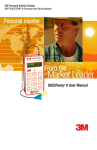
1
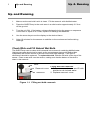
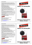
3M Personal Safety Division 3M™ QUESTemp° ™ Heat Stress Monitors ©3M 2013. All Rights Reserved Robust Construction From the From the Market Leader QUESTemp 32 User Manual o ii TABLE OF CONTENTS TABLE OF CONTENTS Up and Running ................................................................................................... 1 Check Wick and Fill Natural Wet Bulb ............................................................... 1 Measurements ...................................................................................................... 2 QUESTemp32 ................................................................................................ 2 Wet Bulb Globe Temperature .......................................................................... 2 Heat Index / Humidex ...................................................................................... 2 Keypad Operation ................................................................................................ 3 I/O Enter .......................................................................................................... 3 Up Arrow.......................................................................................................... 3 Down Arrow ..................................................................................................... 3 Setup ............................................................................................................... 3 Displayed Items .................................................................................................... 3 Placement for monitoring/testing .......................................................................... 4 Sensors ................................................................................................................ 4 Natural Wet Bulb Thermometer ....................................................................... 4 Globe Thermometer......................................................................................... 4 Dry Bulb Thermometer .................................................................................... 4 Relative Humidity Sensor ................................................................................ 5 Remote, Sensors 2 and 3 ...................................................................................... 5 Tri-Sensor Weighted Average ......................................................................... 5 Operational Check ................................................................................................ 5 Power Options ...................................................................................................... 6 9-V Alkaline Battery Replacement ................................................................... 6 Approved 9-Volt Batteries ................................................................................ 6 NiMH Battery Pack .......................................................................................... 7 Specifications ....................................................................................................... 8 Product Markings and Special Conditions ............................................................ 9 Special conditions for safe use: ............................................................................ 9 APPENDIX A: Heat Exposures Tables ............................................................... 10 iii TABLE OF CONTENTS ACGIH ........................................................................................................... 10 United States Navy ........................................................................................ 10 Electrical power research institute (EPRI) ..................................................... 12 APPENDIX B: Accessories .................................................................................. 13 Customer Service ................................................................................................ 14 Contacting 3M Detection ............................................................................... 14 Calibration ..................................................................................................... 14 Warranty ........................................................................................................ 14 1 Up & Running Up and Running Up and Running 1. Make sure the wet bulb’s wick is clean. Fill the reservoir with distilled water. 2. Place the QUESTemp in the work area in a safe location approximately 3.5 feet off the ground. 3. Turn the unit ON. If the battery voltage displayed during the power-on sequence is less than or equal to 6.4 volts, replace or recharge the batteries. 4. Use the arrow keys to set the display to the desired items. 5. Allow 10 minutes for the sensors to stabilize to the environment before taking readings. Check Wick and Fill Natural Wet Bulb The QUESTemp uses a cotton wick immersed into a reservoir containing distilled water. Ordinary tap water should not be used, as the contaminants that are left behind after evaporation will shorten the life of the wick and cause high readings. If the wick is discolored it should be replaced. To replace the wick, slide the old wick off the top of the sensor. Place a new wick over the sensor, making sure that the bottom of the wick is down in the reservoir. Wick Filling wet bulb reservoir Reservoir cover 1. Remove reservoir cover and fill with distilled or de-ionized water. 2. Replace reservoir cover. Reservoir Figure 1-1: Filling wet bulb reservoir 2 Measurements Measurements Measurements QUESTemp32 The QUESTemp32 portable area heat stress monitor computes the Wet Bulb Globe Temperature (WBGT). The WBGT is an accepted measurement for determining the heat stress level imposed on an individual in a given environment. The QUESTemp32 measures three parameters: ambient or dry bulb temperature (DB), natural wet bulb temperature (WB), and globe temperature (G). In addition to the WBGT, the QUESTemp32 measures relative humidity (RH) and computes the Heat Index (HI) or Humidex. The QUESTemp32, using inputs on the side of the instrument, has the ability to connect to two additional sensor arrays for monitoring up to three locations simultaneously. Wet Bulb Globe Temperature The WBGT is a weighted average of the three temperature sensors using the following formulas: WBGT (indoor) = 0.7WB + 0.3G (denoted as “WBGTi” on the display) WBGT (outdoor) = 0.7WB + 0.2G + 0.1DB (denoted as “WBGTo” on the display) NOTE: The resulting WBGT can be compared to indices of work-rest regimens (stay times) based upon the work loads. (Please see Appendix A for published heat exposure tables.) Heat Index / Humidex The Heat Index is determined using the dry bulb temperature and relative humidity. Based upon charts available from the U.S. National Weather Service, Heat Index represents how an average person feels relative to climate conditions. For a constant temperature, if the humidity rises, so does the heat index. The Heat Index is defined over a temperature range of 70F - 120F (21C - 49C) and a relative humidity range of 30% - 99%. Outside of this range, the instrument will show dashes in the display for the Heat Index. The Humidex is used primarily in Canada and is very similar to the Heat Index. The values are slightly different. The Humidex is defined over a temperature range of 70F 109F (21C - 43C) and a relative humidity range of 20% - 99%. Outside of this range, the instrument will show dashes in the display for the Humidex. 3 Keypad Operation Keypad Operation Keypad Operation The unit operates using a membrane keypad with 4 keys. The I/O ENTER key responds when the key is released while all other keys respond when the key is pressed. I/O Enter The unit turns on with a single key press. The unit turns off by holding the key down while a countdown of 3-2-1 occurs in the lower right corner of the display. This key is also used to enter setup changes. While viewing live readings, pressing and releasing the key will cause the display to view the next available sensor bar (indicated in the upper right corner of the display). Up Arrow Changes which items appear in the display. Scrolls up. Down Arrow Changes which items appear in the display. Scrolls down. Setup Allows changing the setup parameters. Three parameters are available: Celsius or Fahrenheit, the language, and Heat Index or Humidex. Press setup to access the parameters. Use the arrow keys to switch between the two parameters. Use the enter key to change the parameters. Press setup again to exit. Displayed Items The number in the upper right corner indicates which sensor bar’s data is displayed. 1 indicates the sensor bar placed on (or attached to) the top of the instrument. Sensors 2 and 3 are labeled on the side of the unit. W indicates the weighted average which only appears if a WBGT is displayed and all three sensor bars are attached. The following measurements can be accessed on the display: Screen 1: WET (WET BULB) DRY (DRY BULB) Screen 2: GLOBE Screen 3: WBGTi (WBGT INDOORS) WBGTo (WBGT OUTDOORS) Screen 4: RH (Relative Humidity) H.I. (Heat Index) or Humidex Screen 5 : BAT (BATTERY VOLTAGE) WET 80.5F DRY 92.2F 1 4 Placement for monitoring/testing Placement Placement for monitoring/testing The QUESTemp should be placed at a height of 3.5 feet (1.1m) for standing individuals or 2 feet (.6m) for seated individuals. Tripod mounting is recommended to get the unit away from anything that might block radiant heat or airflow. A 1/4"x20 threaded bushing on the bottom of the instrument allows mounting to a standard photographic tripod. Do not stand close to the unit during sampling. Make sure that the wet bulb reservoir is filled with distilled water and that the cotton wick is clean and fully wetted. After adding water or placing the unit in a new environment, allow ten minutes for the globe and wet bulb readings to stabilize. A series of dashes appear in the display if one of the following occur: The Heat Index or Humidex is outside of its allowable range The temperature is outside of its allowable range A temperature sensor has failed Sensors Natural Wet Bulb Thermometer The natural wet bulb thermometer gives an indication of the effects of humidity on an individual. Relative humidity and air flow are taken into account by measuring the amount of evaporative cooling taking place at a thermometer covered with a moistened wick. The QUESTemp uses a cotton wick immersed into a reservoir containing distilled water. Ordinary tap water should not be used, as the contaminants that are left behind after evaporation will shorten the life of the wick and cause high readings. If the wick is discolored it should be replaced. To replace the wick, slide the old wick off the top of the sensor. Place a new wick over the sensor, making sure that the bottom of the wick is down in the reservoir. Globe Thermometer The globe thermometer gives an indication of the radiant heat exposure on an individual due to either direct light or hot objects in the environment. This is accomplished by placing a temperature sensor inside a blackened copper sphere and measuring the temperature rise. The WBGT index is based on the response of a 6 inch diameter globe. The QUESTemp uses a 2 inch diameter globe for a faster response time. The temperature of the 2 inch globe is correlated to match that of a 6 inch globe. As an option, a sensor array with a 6 inch diameter globe is available. Dry Bulb Thermometer The dry bulb thermometer measures the ambient air temperature. This measurement is used in the outdoor WBGT calculation when a high solar radiant heat load may be present. The series of white plates surrounding the sensor shield it from radiant heat. 5 Remote, Sensors 2 and 3 Remote, Sensors 2 & 3 Relative Humidity Sensor A relative humidity sensor is located in a compartment inside of the sensor bar housing. Slots in the housing allow air to circulate around the sensor. Remote, Sensors 2 and 3 The top sensor bar (sensor 1) may be removed from the instrument and used through a remote cable. Shelter the instrument and remote the sensor bar if the measured environment is expecting heavy rain or if temperatures are above 60C. The sensor 2 and sensor 3 jacks on the side of the instrument allow simultaneous monitoring of up to three sensor arrays using connecting cables. Cable lengths of up to two hundred feet (61 meters) may be used without a decrease in accuracy provided the environment does not contain strong electromagnetic fields. The data from these arrays may be viewed separately or combined into a weighted average WBGT reading per ISO 7243. Change the displayed sensor bar by pressing and releasing the enter key. The upper right corner of the display shows the current sensor bar. 1 refers to the top sensor bar, 2 and 3 are labeled on the side of the unit, W indicates the weighted average which only appears if a WBGT is displayed and all three of the sensor bars are attached. Tri-Sensor Weighted Average Per the recommendations outlined in ISO 7243 :1989, when the temperature in the space surrounding a worker is not uniform, it is necessary to determine the WBGT index at three heights corresponding to the worker's ankles, abdomen and head and perform a weighted average on those values. It is computed using the formula: WBGTw = (WBGThead + (2 x WBGTabdomen) + WBGTankles)/4 The QUESTemp always assigns the top sensor bar the double weighting. This calculation is shown if a WBGT display has been selected and if 3 sensor sets are connected. Operational Check A verification module, Quest model 054-544, may be used to check the operation of the QUESTemp. Remove the top sensor bar and plug the verification module into the top of the unit. With the QUESTemp set to read in degrees Celsius, verify that the displayed readings match those printed on the module within +/-0.5C. If the readings are not within the +/-0.5C tolerance, then have the unit serviced and calibrated. 6 Power Options Power Options Power Options There are 3 options for powering the QUESTemp: a 9-volt alkaline battery, a NiMH (Nickel Metal Hydride) rechargeable 6-cell battery pack, and an AC adapter. A door on the back of the unit allows the user access to the 9-volt battery. The rechargeable battery pack is located inside of the unit. If the rechargeable battery pack ever needs to be replaced, it can be accessed by removing the screws from the bottom panel of the unit. The 2-position switch located in the battery compartment must be set by the user if the power supply method is changed. The up position is for the 9 volt battery. The down position allows for either the AC adapter or the rechargeable batteries. The AC adapter will trickle charge the rechargeable batteries if they are in place or it will simply allow for line power operation of the unit. 9-V Alkaline Battery Replacement WARNING: Replace batteries only in a non-hazardous environment. The 9-volt battery should be replaced or the NiMH battery pack should be recharged when the voltage drops below 6.4 volts. The battery voltage is displayed when the instrument is turned on. While turned on, the battery voltage can be displayed at any time by pressing the up or down arrow keys to move through the display until the battery voltage screen appears. If, while operating, the battery voltage drops below 6.4 volts, the display will automatically switch to the display showing the battery voltage along with a low battery message. After a low battery occurs, the unit will continue to operate for approximately 8 hours. When the battery voltage falls to 6.2 volts or below, the unit will automatically turn off. Replace only with an approved 9-volt alkaline battery. Approved 9-Volt Batteries Eveready: Energizer 522, EN22, 6LR61 Duracell: MN1604 Panasonic: 6LR61, 6AM6X Rayovac: A1604 UltrLife: U9V 7 Power Options Battery Pack NiMH Battery Pack WARNING: Recharge batteries only in a non-hazardous environment. The NiMH rechargeable battery pack is charged in the instrument using Quest’s AC adapter #015-910. A discharged battery pack requires an “overnight” charge of 16 hours. Leaving the AC adapter plugged in for extended lengths of time or when operating the instrument will not harm the rechargeable batteries. 8 Specifications Specifications Specifications Measurements Globe, dry bulb, wet bulb, WBGTin, WBGTout, WBGT weighted average (if 3 sensor sets), relative humidity, Heat Index, Humidex. Temperatures given in Celsius or Fahrenheit. Languages English, French, Spanish, Italian, German. Housing Designed water resistant to a light rain or mist. If rain is frequent, best practice would be to remote the sensor bar and keep the instrument sheltered. Size Height 9.2in (23.5cm); Width 7.2in (18.3mm); Depth 3.0in (7.5mm) Dimensions include mounted sensor assembly. Weight 2.6 lbs. (1.2 kg) with mounted sensor assembly. Sensor Types Temperature: 1000 ohm platinum RTD Humidity: Integrated circuit with capacitive polymer sensor Accuracy Temperature: +/-0.5C between 0C and 120C Relative Humidity: +/-5% between 20 to 95% (non-condensing) Operating Temperature Range Sensor Assembly: -5C to +100C Electronics: -5C to 60C Remote Sensor Bars 2 x 15pin D-sub jacks are located on the side of the unit for plugging in 1 or 2 additional sensor bars by using remote cables up to 200 feet (61m). The top sensor bar can also be remote with a cable. Power Options 9V alkaline, 7.2V NiMH rechargeable pack (charged in the unit), or AC adapter wall power cube (AC adaptor will operate the unit or recharge the NiMH battery pack). 9 Product Markings and Special Conditions Battery Life 9V alkaline: 140 hours Rechargeable Nickel Metal Hydride: 300 hours (Adding additional sensor bars reduces battery life.) Charge Time (NiMH Battery Pack) 16 hours (charge in the unit) Safety Approvals ETL, cETL: Class I,II,III Groups A,B,C,D,E,F,G, Temperature code T3 KEMA 04ATEX1072 X <Ex> II 2 G EEx ia IIC T3 CE mark Product Markings and Special Conditions KEMA 04ATEX1072 X <Ex> II 2 G EEx ia IIC T3 Compliance with Essential Health and Safety Requirements has been assured by compliance with: EN 50014 : 1997 and EN 50020 : 2002 The year of manufacture is determined by the third character in the instrument’s serial number. “A” was manufactured in 2001, “B” in 2002, “C” in 2003, “D” in 2004 and so forth. Special conditions for safe use: 1. Only the following battery types may be used: Non-rechargeable battery: Type Manufacturer U9V Ultralife MN1604 Duracell 522 or EN22 or 6LR61 Energizer A1604 or BR232 Rayovac 6LR61 or 6AM6 Panasonic Rechargeable battery: Integral NiMH battery pack type DC2121. 2. The batteries may not be replaced or charged within the hazardous area. 3. The rechargeable battery may only be recharged with class 2 charger, rated 9Vdc, 1 A max. 4. The plugs or sockets market “SENSOR 2” and “SENSOR 3” may not be used within the hazardous area. Appendix A: 10 Heat exposure tables APPENDIX A: Heat Exposures Tables APPENDIX A: Heat Exposures Tables ACGIH Screening Criteria for Heat Stress Exposure. WBGT values in C. NOTE: according to the ACGIH’s guidelines, the temperature values represent a work and rest process which is explained in the standards. Please refer to the ACGIH TLV’s and BEIs for specific details. Work and recovery (TLV ) 75% to 100% 50% to 75% 25% to 50% 0% to 25% Light Work and recovery (Action Limit) 75% to 100% 50% to 75% 25% to 50% 0% to 25% Light 31.0 31.0 32.0 32.5 28.0 28.5 29.5 30.0 Moderate 28.0 29.0 30.0 31.5 Moderate 25.0 26.0 27.0 29.0 Heavy Very Heavy 26.0* 27.5 29.0 30.5 Heavy 23.5* 25.5* 28.0 30.0 Very Heavy 22.5* 24.0 25.5 28.0 20.0* 22.5* 24.5 27.0 *Values not specified by ACGIH have been estimated for continuity. Cited from "American Conference of Governmental Industrial Hygienists Threshold Limit Values and Biological Exposure Indices for 2008"; Reprinted with permission from ACGIH United States Navy Physiological Heat Exposure Limits (PHEL) Time Table (Without the presence of fuel combustion gases/fuel vapors) is displayed on the following page. The recommended working hours are shown based on a maximum of eight hours. Naval personnel will follow a category, I - VI, based upon their function. 11 APPENDIX A: Heat Exposures Tables PHEL Curves (Total Exposure Time in Hours: Minutes) WBGT(F) I II III IV V VI 80.0 >8:00 >8:00 >8:00 8:00 6:35 4:30 81.0 82.0 83.0 84.0 85.0 86.0 87.0 88.0 89.0 90.0 91.0 >8:00 >8:00 >8:00 >8:00 8:00 8:00 7:25 6:45 6:10 5:40 5:15 >8:00 >8:00 8:00 8:00 7:45 7:05 6:30 5:55 5:25 5:00 4:35 >8:00 8:00 7:45 7:05 6:30 5:55 5:25 4:55 4:30 4:10 3:50 8:00 7:05 6:25 5:55 5:20 4:55 4:30 4:05 3:45 3:25 3:10 6:35 5:25 4:55 4:30 4:05 3:45 3:25 3:10 2:50 2:40 2:25 4:30 3:40 3:20 3:05 2:50 2:35 2:20 2:10 2:00 1:50 1:40 92.0 93.0 94.0 95.0 96.0 97.0 98.0 99.0 100.0 101.0 102.0 103.0 104.0 105.0 106.0 107.0 108.0 109.0 110.0 111.0 112.0 113.0 114.0 115.0 116.0 117.0 118.0 119.0 120.0 121.0 122.0 123.0 124.0 4:50 4:25 4:05 3:45 3:25 3:10 2:55 2:40 2:30 2:20 2:10 2:00 1:50 1:40 1:35 1:30 1:20 1:15 1:10 1:05 1:00 0:55 0:55 0:50 0:45 0:45 0:40 0:35 0:35 0:35 0:30 0:30 0:25 4:10 3:50 3:35 3:15 3:00 2:45 2:35 2:20 2:10 2:00 1:50 1:45 1:35 1:30 1:25 1:15 1:10 1:05 1:00 1:00 0:55 0:50 0:45 0:45 0:40 0:40 0:35 0:35 0:30 0:30 0:25 0:25 0:25 3:30 3:15 3:00 2:45 2:30 2:20 2:10 2:00 1:50 1:40 1:35 1:25 1:20 1:15 1:10 1:05 1:00 0:55 0:50 0:50 0:45 0:40 0:40 0:35 0:35 0:30 0:30 0:25 0:25 0:25 0:20 0:20 0:20 2:55 2:40 2:25 2:15 2:05 1:55 1:45 1:40 1:30 1:25 1:15 1:10 1:05 1:00 0:55 0:50 0:50 0:45 0:40 0:40 0:35 0:35 0:30 0:30 0:25 0:25 0:25 0:20 0:20 0:20 0:15 0:15 0:15 2:15 2:00 1:50 1:45 1:35 1:25 1:20 1:15 1:10 1:05 1:00 0:55 0:50 0:45 0:45 0:40 0:35 0:35 0:30 0:30 0:25 0:25 0:25 0:20 0:20 0:20 0:15 0:15 0:15 0:15 0:15 0:10 0:10 1:30 1:25 1:15 1:10 1:05 1:00 0:55 0:50 0:45 0:45 0:40 0:35 0:35 0:30 0:30 0:25 0:25 0:25 0:20 0:20 0:20 0:15 0:15 0:15 0:15 0:10 0:10 0:10 0:10 0:10 0:10 0:10 0:05 12 APPENDIX A: Heat Exposures Tables Electrical power research institute (EPRI) The recommended working hours are shown based on a maximum of four hours. A time of 4:01 indicates greater than 4 hours. WBGT°C 28 29 30 31 32 33 34 35 36 37 38 39 40 41 42 43 44 45 46 47 48 49 50 Light 4:01 4:01 4:01 4:01 4:00 3:30 3:00 2:30 2:00 1:45 1:30 1:15 1:00 0:53 0:45 0:38 0:30 0:28 0:25 0:23 0:20 0:18 0:15 Moderate 4:01 4:00 3:00 2:00 1:30 1:15 1:00 0:53 0:45 0:40 0:35 0:33 0:30 0:28 0:25 0:23 0:20 0:18 0:15 0 0 0 0 Heavy 3:00 2:00 1:30 1:15 1:00 0:45 0:40 0:35 0:30 0:25 0:20 0:18 0:15 0 0 0 0 0 0 0 0 0 0 13 Appendix B: APPENDIX B: Accessories Accessories APPENDIX B: Accessories Sensor array with 2 inch globe 56-795 Sensor array with 6 inch globe 56-780 6 Foot shielded remote sensor cable 53-924 25 Foot shielded remote sensor cable 53-925 100 Foot shielded remote sensor cable 53-926 200 Foot shielded remote sensor cable 53-927 120VAC to 9VDC adapter 15-910 220VAC to 9VDC adapter 15-680 Verification module 53-923 Tripod 59-045 Replacement wicks 56-679 Water bottle 2 oz. 56-068 User’s manual 56-661 14 Customer Service Customer Service Contacting 3M Detection Should your 3M equipment need to be returned for repair or for recalibration, please contact the service department at the following number or access the online form via the website. For technical issues, please contact Technical Support. Should your 3M equipment need to be returned for repair or for recalibration, please contact the service department at the following number or access the online form via the website. For technical issues, please contact Technical Support. Service Department and Technical Support: 1 (800) 245-0779. Fax: 1 (262) 567-4047. Office hours are 8:00 a.m. to 5:00 p.m. United States Central. E-mail: [email protected] Website: www.3M.com/detection Calibration The QUESTemp⁰ 32 should be examined regularly by the factory. An annual calibration is recommended. (Please see Service Department above.) Warranty 3M warrants our instruments to be free from defects in materials and workmanship for one year under normal conditions of use and service. For United States customers, we will replace or repair (our option) defective instruments at no charge, excluding batteries, abuse, misuse, alterations, physical damage, or instruments previously repaired by other than 3M. Microphones, sensors, printers, and chart recorders may have shorter or longer warranty periods. This warranty states our total obligation in place of any other warranties expresses or implied. Our warranty does not include any liability or obligation directly resulting from any defective instrument or product or any associated damages, injuries, or property loss, including loss of use or measurement data. For warranty outside the United States, a minimum of one year warranty, applies subject to the same limitation and exceptions as above with service provided or arranged through the authorized 3M distributor or our 3M European Service Laboratory. Foreign purchases should contact the local 3M authorized sales agent for details. About Us 3M Detection Solutions is a world class manufacturer of rugged, reliable instrumentation and software systems that help monitor and evaluate occupational and environmental health and safety hazards, including noise dosimetry, sound level monitoring, heat stress, indoor air quality and select toxic/combustible gases. The 3M Detection brand of instrumentation is used by safety and industrial hygiene professionals to help comply with applicable occupational standards and regulations. About 3M Personal Safety 3M offers a comprehensive, diverse portfolio of Personal Safety solutions providing respiratory protection, hearing protection, fall protection, reflective materials for high visibility, protective clothing, protective eyewear, head and face protection, welding helmets, and other adjacent products and solutions such as tactical safety equipment, detection, monitoring equipment, active communications equipment and compliance management. In 2012, 3M celebrated 40 years of safety leadership – recognizing the company’s respiratory and hearing protection solutions introduced in 1972. Visit www.3M.com/PPESafety or http://m.3m.com/PPESafety for details. Personal Safety Division 3M Detection Solutions 1060 Corporate Center Drive Oconomowoc, WI 53066 ISO 9001 Registered Company ISO 17025 Accredited Calibration Lab Customer Service: 262-567-9157 Toll Free: 800-245-0779 www.3m.com/detection 3M is trademark of 3M Company used under license in Canada Please recycle. Printed in USA. © 2013 3M All rights reserved. 056-661, Rev.G 2/13