1
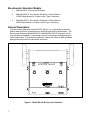
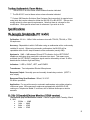
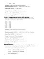
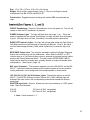
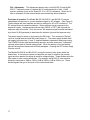
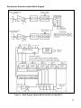
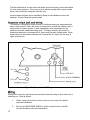
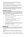
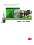
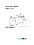
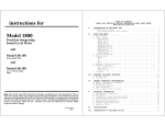
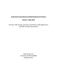
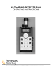
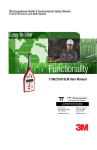
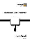
3MTM Personal Safety Division Bio-Acoustic Simulators Durable, Simplistic Functionality BA-202 Models User Manual Bio- Acoustic Simulators Owner’s manual for Bio-Acoustic Simulator models: BA-202 Bio-Acoustic Simulator User Manual BA-202-25 includes Octave Monitor with OSHA Requirements BA-202-27 includes Octave Monitor with ANSI Requirements 053-012 Rev. D, 6/13 Table of Contents Bio-Acoustic Simulator Models .......................................................................................... 1 Model BA-202 Bio-Acoustic Simulator ........................................................................ 1 Model BA-202-25 Bio-Acoustic Simulator & Octave Monitor ....................................... 1 Model BA-202-27 Bio-Acoustic Simulator & Octave Monitor ....................................... 1 General Description ........................................................................................................... 1 Operating Procedure ......................................................................................................... 3 Operation Outside of the Audiometric Room ................................................................. 3 Operation Inside of the Audiometric Room ................................................................... 3 Microphone Location (BA-202-25 and BA-202-27) ....................................................... 4 Battery Test (Battery Operation Only) ........................................................................... 4 General Considerations ................................................................................................. 4 Testing a Manual Audiometer ....................................................................................... 6 Testing an Automatic Audiometer ................................................................................. 6 Testing Audiometric Room Noise (BA-202-25 & BA-202-27)........................................ 7 Testing Audiometric Room Notes: ................................................................................. 8 Specifications..................................................................................................................... 8 Bio-Acoustic Simulator (BA-202 model) ........................................................................ 8 BA-202-25 (model) Octave Monitor (OSHA version) .................................................... 8 BA-202-27 (model) Octave Monitor (ANSI version) ...................................................... 9 General Features .......................................................................................................... 9 Controls (See Figures 1, 2, and 3) .............................................................................. 10 Response output jack and wiring ................................................................................ 13 Battery Replacement ................................................................................................... 14 Volt Power Adapter ..................................................................................................... 14 Maintenance and Calibration ....................................................................................... 14 Headphone Calibration Check (Left/Right Earphone) ................................................. 14 Octave Monitor Calibration .......................................................................................... 15 Microphone Care ......................................................................................................... 15 Preamplifier Care ........................................................................................................ 16 3M Customer Service and Warranty Policy ..................................................................... 16 Contacting 3M Instrumentation ................................................................................... 16 International customers ............................................................................................... 16 Calibration........................................................................................................................ 16 Warranty .......................................................................................................................... 17 Bio-Acoustic Simulator Models Model BA-202 Bio-Acoustic Simulator Model BA-202-25 Bio-Acoustic Simulator & Octave Monitor OSHA Requirements for Octave Levels (Type 2 accuracy) Model BA-202-27 Bio-Acoustic Simulator & Octave Monitor ANSI Requirements for Octave Levels (Type 1 accuracy) General Description The Bio-Acoustic Simulator model BA-202 (Figure 1) is a high-quality measuring device used to fulfill the requirements for daily biological tests of audiometers. The Bio-Acoustic Simulator Model BA-202-25 and Model BA-202-27 (Figures 2 and 3) also provide the capability to continuously monitor room noise in octaves during an actual hearing test. This ensures compliance to either the OSHA or ANSI allowable background noise limits for audiometric test rooms. Figure 1: Model BA-202 Bio-Acoustic Simulator 1 Figure 2: Model BA-202-25 Bio-Acoustic Simulator & Octave Monitor (OSHA) Figure 3: Model BA-202-27 Bio-Acoustic Simulator & Octave Monitor (ANSI) 2 The BA-202 series simulator is simply substituted for a human test subject, thus eliminating the need to use the same person with a known hearing threshold level. The Bio-Acoustic Simulator’s performance is consistent every day. This eliminates the variables that can be present when using a human test subject whose hearing can be affected by such things as a head cold, allergy, recreational noise exposure, etc. Either model will provide a reference audiogram when the simulator is connected to a manual or automatic audiometer. Audiometric room background noise can easily be monitored during the audiogram by using the Octave Monitor capability of the BA-202-25 (OSHA levels) or BA-202-27 (ANSI levels). Other factory-set octave levels can be special ordered if requested by the purchaser. The unit is intended to be wall-mounted in an audiometer test room. However, the unit can be operated as a table-top unit outside of the test room if desired. When used in this manner, the 4 rubber feet (sticky adhesive backing, provided) will need to be installed on the back four corners of the unit. When performing the biological check, the headphones have to be unplugged from the room connection jacks, brought to the location of the audiometer and simulator, and reconnected to the audiometer jacks. Also, for the BA-202-25 and BA-202-27, the microphone cable must also go from the unit to the inside of the audiometric room and must hang down from the ceiling (with only 10 feet of microphone cable provided). Considering these inconveniences, it is much easier to use the unit when mounted inside of the audiometric room on the wall as follows: All models have been designed to be mounted on an inside wall of an audiometric room with two screws (pan head style, not provided) and a Velcro ® patch (provided). A suggested location would be on the inside of the test room on the wall opposite the operator's viewing window. It should also be located where the subject's head will not interfere with the viewing of the indicator lights. When a good location is determined, fasten the unit as follows: 3 1. Locate the long slot on the back of the chassis. This slot is intended to slide onto the screw heads. The 4 rubber feet are not used when wall-mounting the unit. 2. Mark the location for the two mounting screws, approximately 3½ inches apart. 3. If necessary, make two small "starting" holes in the room wall for the screws. 4. Screw the two screws into the wall. Let the screw heads protrude just far enough so that the long slot on back of the unit will slide onto them. Test to be sure that the unit slides onto the screw heads. 5. There are two Velcro® patches on the back of the unit. The "hook" patch is fastened to the unit; the "loop" patch is stuck onto the "hook" patch. Peel the backing from the "loop" patch. 6. Slide the unit onto the screw heads while holding the sticky Velcro® patch surface away from the wall. 7. Once the unit is centered on the screw heads, press the bottom of the unit firmly against the wall so that the patch sticks to the wall. 8. The unit is now fastened securely. The Velcro® holds the unit from sliding sideways off of the screws. To remove the unit from the wall, pull the bottom away from the wall to separate the Velcro®. Then slide the unit to the side. After sticking the unit's patch to the wall, you may want to remove the unit from the wall and firmly press the Velcro® patch to the wall to ensure proper bonding. These models require the use of a cable-mounted microphone to operate the octave band filters. It is recommended that the microphone be suspended by its cable close to the ceiling of the audiometric room. Also locate it in the best position so that the test subject's head will not interfere with it when entering and leaving the room. Be sure to attach the cable in such a fashion so that it can be easily removed from the ceiling mount for periodic calibration. The use of a "screw-type" hook is one way to attach it. Since room ceiling material varies, use the best method for that type of material. Press the ON button to turn the power on. The POWER indicator lamp will flash, indicating that the battery voltage is sufficient. If this light does not flash, the battery is too low to operate the unit. When the battery weakens and approaches the end of its useful life, the intensity of the flashing will lessen and finally disappear. The Bio-Acoustic Simulator section checks the audiometer earphones in the 45dB HL to 75 dB HL range. Therefore, it is important to have a relatively quiet background when performing the HL tests. All tests should be performed within an audiometric room for best results. An original BIOLOGICAL LOG should always be made when the audiometer has just come back from having an exhaustive calibration. Every successive BIOLOGICAL LOG should then be compared against the original. By doing this, as long as the new HL values are within ± 5dB of the original BIOLOGICAL LOG, the audiometer 4 accuracy is acceptable to begin testing of patients. See Table 1, page 8, for typical HL values for audiometers with 5dB HL steps. Table 1 requires that you know the model of headphone that your audiometer uses. Refer to the audiometer instruction manual. If you can't find out from the manual, you will need to disassemble one earphone (removing either the red or blue cup) to read the model of the headphone. 5 A typical test procedure would be as follows: 1. Switch the audiometer on and allow it to stabilize per manufacturer's specifications. 2. Place the earphones onto the Bio-Acoustic Simulator. 3. Turn the Bio-Acoustic Simulator on. 4. Starting at 125 Hz (or the lowest frequency) and 40dB HL on the Left (Blue) earphone, increase the HL value until the LEFT indicator light appears. Repeat a few times to be confident of the HL value. Record the HL value. Repeat this step for all frequencies on the audiometer. 5. Repeat step 4 with the Right (Red) earphone. 6. Keep a BIOLOGICAL LOG of this data. Always compare the new HL values to the original BIOLOGICAL LOG that was established early in the present calibration interval of the audiometer. All data should compare within ± 5dB of the original BIOLOGICAL LOG. See Table 1, page 8, for HL value ranges. A typical test procedure would be as follows: 1. Switch the audiometer on and allow it to stabilize per manufacturer's specifications. 2. Connect the RESPONSE CABLE (059-995) between the patient response jack of the audiometer and the RESPONSE jack of the Bio-Acoustic Simulator. 3. Place the earphones onto the Bio-Acoustic Simulator. 4. Turn the Bio-Acoustic Simulator on. 5. Run the audiometer through its normal testing sequence. An audiogram will be produced. 6. Keep a BIOLOGICAL LOG of this data. Always compare the new HL values to the original BIOLOGICAL LOG that was established early in the present calibration interval of the audiometer. All data should compare within ± 5dB of the original BIOLOGICAL LOG. See Table 1, page 8, for typical HL values. 6 FREQUENCY TDH-39 125 250 500 750 1K 1.5K 2K 3K 4K 6K 8K TDH-49 TDH-50 50 to 65 60 to 70 60 to 70 60 to 70 55 to 65 55 to 65 50 to 60 50 to 60 50 to 65 50 to 65 55 to 70 55 to 70 60 to 70 60 to 70 60 to 70 55 to 65 55 to 65 55 to 65 50 to 60 50 to 65 45 to 60 55 to 70 TELEX 1470 55 to 70 60 to 70 60 to 70 60 to 70 60 to 70 55 to 65 60 to 70 55 to 65 55 to 70 55 to 70 60 to 75 INSERT EARPHONE 55 to 70 55 to 70 55 to 70 55 to 70 55 to 70 55 to 70 55 to 70 55 to 70 55 to 70 55 to 70 55 to 70 Table 1: Typical HL Values for Various Earphones on Audiometer with 5dB Attenuator Steps. These levels are just for reference to see if the audiometer is relatively correct the first time that it is tested. Room noise within an audiometric room can be tested either continuously or periodically depending on various conditions that are producing the noise. However, Quest recommends that this test be performed continuously while test subjects are being evaluated. Testing is performed as follows: 1. Hang the microphone from the ceiling slightly above the test subject's head. 2. Turn the BA-202-25 or BA-202-27 on. 3. With the door closed, occasionally view the frequency indicator lights on the monitor. They should not be on. If the frequency lights are activating at random, these frequencies are in violation and the subject's test should be halted. The offending sound source(s) should then be located and eliminated. If elimination is not possible, either the audiometric booth should be moved to a quieter location or the test should be scheduled for a more quiet time. See Table 2, page 9, for the allowable values. Frequency (in Hz) 125 250 500 1K 2K 4K 8K OSHA Values 8-Mar-83 * --------40dB 40dB 47dB 57dB 62dB ANSI Values S3.1, 1999 ** 35dB 25dB 21dB 26dB 34dB 37dB 37dB Values on Special Order *** dB dB dB dB dB dB dB Table 2: Allowable Room Noise Specified by Various Regulations 7 * The BA-202-25 is set at these values unless otherwise indicated. ** The BA-202-27 is set at these values unless otherwise indicated. *** Contact 3M Detection Solutions (See Customer Service section) for special room noise limits that can be ordered on either the BA-202-25 or BA-202-27. 3M can also modify values for other special requirements. Note that there is a charge for this modification. Write special values here for reference if you wish to do so. Test Frequencies: 125Hz to 8kHz Calibration: 60 HL 1dB at 1kHz continuous tone with TDH-39, TDH-49, or TDH50 earphones. Accuracy: Repeatable to within 2 dB when using an audiometer with a continuously variable HL control. When using automatic audiometers, the BA-202 will be repeatable within the HL step increments of the audiometer (usually 5dB). Hysteresis: 10dB 1dB between ON and OFF indication for the LEFT/RIGHT headphone indicators when used with continuous tone input. This means once activated, the LEFT/RIGHT headphone signal must be lowered by at least 10 dB to deactivate the Indicator Light and Relay. Indicators: 3 LED’s; RIGHT, LEFT, and POWER. Transducers: Two independent Electret Microphones. Response Output: Normally open and normally closed relay contacts. (SPDT 3wire output). Response Relay Specifications: 250mA, 30 V DC. 20 million operations. Application: For use with manual or automatic audiometers using either pulsed or continuous tones. Will measure all earphones equipped with either MX-41/AR cushions or Telephonics Model 51 cushions, with or without Audiocups or similar earmuffs. Test Octaves (Hz) and Activation Levels: Federal Register dated Tuesday, March 8, 1983. 500Hz -- 40dB 1kHz -- 40dB 2kHz -- 47dB 4kHz -- 57dB 8 8kHz -- 62dB Indicators: 5 LED’s; One for each monitored frequency. Microphone/Amplifier: ANSI S1.4 - 1983 & S1.4A - 1985, Type 2 Octave Filters: ANSI S1.11 - 1986, Class II Preamp: Cable-mounted FET type for electret microphone. Microphone: Quest QE7052 (1/2”) Type 2 electret. Calibration: Requires 114dB, 1kHz acoustical calibrator (such as the Quest QC-10) Test Octaves (Hz) and Activation Levels: per ANSI S3.1, 1999, MAXIMUM PERMISSIBLE AMBIENT NOISE LEVELS FOR AUDIOMETRIC TEST ROOMS, Table 1, Supra-aural Earphone, 125Hz to 8000Hz. 125Hz 250Hz 500Hz 1kHz 2kHz 4kHz 8kHz -------- 35dB 25dB 21dB 26dB 34dB 37dB 37dB Indicators: 7 LED’s; One for each monitored frequency. Microphone/Amplifier: ANSI S1.4 - 1983 & S1.4A - 1985, Type 1 (Precision) Octave Filters: ANSI S1.11 - 1986, Class II Preamp: Cable-mounted FET type for condenser microphone. Preamp is supplied with 200VDC. Microphone: Quest QE4170 (1”) Type 1 condenser. Calibration: Requires 114dB, 1kHz acoustical calibrator (such as the Quest QC-10) Power and Battery Life: 9 volt alkaline battery. Uses flashing LED as “Good Battery Indicator”. Battery life will vary depending on how many LED’s are on and for what length of time. If battery life is not adequate in your application, use one of the following optional power adapters (battery eliminators): 015-910 015-680 120 Vac to 9 VDC, unregulated 220 Vac to 9 VDC, unregulated Note: Center terminal is "+". 9 Size: 173 x 165 x 107 mm (6.8 x 6.5 x 4.2 inches) Weight: Each model is approximately 740 g (1.6 lb) not including the remote microphone of the BA-202-25 and BA-202-27. Construction: Rugged aluminum housing with molded ABS polycarbonate ear cups. ON/OFF Pushbuttons: Press the ON pushbutton to turn the power on. The unit will remain on until the OFF pushbutton is pressed. POWER Indicator Light: This light will flash when the power is on. When the power is supplied with the internal 9-volt battery, the light will flash when the battery is good. If the light does not flash, the battery is low and requires replacement. RIGHT/LEFT Indicator Lights: One light will activate when either the Right (Red) or Left (Blue) earphone output exceeds an internally set dB level. Once lit, the signal must be reduced approximately 10dB (called “hysteresis”) to cause the light to go out. RESPONSE Output Jack: This output is intended to replace the Patient Response Switch that normally plugs into the audiometer. When either the RIGHT or LEFT indicator lamp is on, the internal relay contact is operated to simulate the test subject pressing the Patient Response Switch. The relay contact (RESPONSE CABLE) output can be wired for normally open, normally closed, or single pole double throw configurations. (See Figure 5, page 15) MIC. Input Connector: This connector appears only on the BA-202-25 and the BA202-27. It allows the external preamp and microphone system to be connected for making audiometric room background noise measurements in octave bands. 125, 250, 500, 1K, 2K, 4K, 8K Indicator Lights: These lights appear on the BA202-27. (The BA-202-25 does not have 125 and 250.) Each individual light will activate if the room noise in the corresponding octave band exceeds the internal preset level. ADAPTER Input Jack: Optional. Allows the unit to be powered by a 9 VDC power cube. Quest Part Numbers: 015-910 015-680 120 Vac to 9 VDC, unregulated 220 Vac to 9 VDC, unregulated Note: Center terminal is "+". 10 CAL. Adjustment: This adjustment appears only on the BA-202-25 and the BA202-27. It allows the user to calibrate the 1K octave band with a 1kHz, 114dB acoustic calibrator (such as the Quest QC-10 or QC-20 calibrators). When the 1K filter is calibrated, all other octave bands are automatically within calibration. Principles of operation The Models BA-202, BA-202-25, and BA-202-27 use two independent microphones to convert earphone signals to AC voltages. (See Figure 4) These voltages are then amplified and sent to rectifiers for AC to DC conversion. The DC voltage enters its respective detector. When sufficient signal is present at the earphone coupler, the appropriate indicator light (RIGHT or LEFT) will light and the response relay will activate. Once this occurs, the earphone signal must be decreased by at least 10 dB (hysteresis) to deactivate the indicator light and the response relay. The power supply is turned on by pressing the ON button. This causes the "flip-flop" circuit to change state and hold the power supply on. The power supply divides the 9volt supply to produce the +V and -V supplies needed to operate all remaining circuitry. The POWER indicator light flashes during operation and also serves as a "low battery" indicator when used on internal battery power. When the battery is low, the flashing light will become less intense and will finally disappear. Pressing the OFF button simply turns the unit off. The Models BA-202-25 and BA-202-27 contain the extra circuitry shown within the dotted lines. A microphone system and amplifier are used to condition the acoustic signal and then present this signal to resistive voltage dividers. These dividers allow the filter inputs to have various sensitivities. For example, the BA-202-27 uses resistive dividers to set levels to 35dB at 125Hz, 25dB at 250Hz, 21dB at 500Hz, etc. These divided signals then go to the inputs of the octave band filters. 11 Bio-Acoustic Simulator models Block Diagram Figure 4: Block Diagram, Models BA-202, BA-202-25, & BA-202-27 12 The filter and detector circuits select and detect various frequency components within the room noise spectrum. If the room noise is intense enough within a given octave band, it will activate the respective indicator light. Various resistor dividers can be installed by Quest to allow different levels to be detected. Contact Quest for special orders. This feature is designed to take the place of a patient pressing the response switch when a tone is heard. When the tone is loud enough to activate the indicator light, a relay contact is closed, opened, or both, depending on the requirement for the particular automatic audiometer being used. This relay actuation will cause the audiometer attenuator to decrease its HL output until the relay is deactivated. When deactivated, the audiometer attenuator will increase the HL output until the relay is again activated, etc. . Figure 5: Response Jack Wiring Wiring of the connector will require some technical expertise using an ohm meter and a soldering iron. Wire as follows: 13 1. Obtain a plug that is similar to the one that is on the end of the patient response handswitch. 2. Wire it to the RESPONSE CABLE so that the relay function of the BioAcoustic Simulator mimics the handswitch. Note: See Figure 5, page 15. If the patient response switch of the audiometer is normally open, use the WHITE and BLACK wires of the RESPONSE CABLE. If the patient response switch of the audiometer is normally closed, use the RED and BLACK wires. If a single pole double throw contact arrangement is required, use the BLACK wire as the common, the WHITE wire as normally open, and the RED wire as normally closed. 3. Be sure to provide ample strain relief to the plug so that the cord does not accidentally pull out of the plug too easily. If help is needed to determine the wiring, Quest can help you with this. The battery compartment is located on the top side of the unit. Replace the battery as follows: 1. Open the battery compartment by lifting the side of the battery door that has the four long bumps on it. 2. Lift the battery out of the compartment. 3. Remove the old battery from the battery snap. 4. Replace with a new 9-volt "alkaline" battery. Note: The battery MUST be of the alkaline variety! If the battery life is not adequate in your application, an optional power adapter is available to save on battery consumption. The 9 volt adapter is simply plugged into the ADAPTER jack on the unit. Battery power is automatically disconnected from the circuit whenever the adapter is connected. The following adapters are available from Quest: 015-910 015-680 120 Vac to 9 VDC, unregulated 220 Vac to 9 VDC, unregulated Note: Center terminal is "+". The Bio-Acoustic Simulator section should maintain its accurate calibration for many months of use. Since both the LEFT and RIGHT test circuits are identical, the following procedure can be used to verify that the Bio-Acoustic Simulator section is functioning properly. Turn the unit on. 14 Place the headphones onto the simulator with the Right (Red) earphone in the coupler on the side marked RIGHT. Test and record the HL values in 5dB increments (45, 50, 55, etc.) at all frequencies. Remove the headphones, turn them around, and place the same Right (Red) earphone in the other coupler on the side marked LEFT. Again, test and record the HL values in 5dB increments (45, 50, 55, etc.) at all frequencies. Compare both sets of data. If the difference between both sets of data is 5 dB or less at each frequency, the Bio-Acoustic Simulator is functioning properly. If it is more than 5 dB at any frequency, the unit should be sent in for calibration/repair. (See QUEST SERVICE and WARRANTY POLICIES) The Octave Monitor section should maintain its accuracy for many months of use. However, to insure consistently accurate operation, it is recommended that the 1K filter be tested and calibrated weekly or at least monthly. Calibration of the 1K filter requires a 1kHz, 114dB acoustic calibrator capable of adapting to the microphone diameter. Quest Calibrators meeting this requirement are the QC-10 (1kHz, 114dB) and the QC-20 (1kHz / 250 Hz, 114dB / 94dB). 1. Switch the calibrator on. Note: If other settings are available, make sure that they are set to produce a 1kHz tone at 114 dB. 2. Place the microphone into the calibrator. When using the ½-inch microphone, use the ½ inch to 1 inch adapter between the calibrator and the microphone. When using the 1-inch microphone, an adapter is not required. 3. Turn the BA-202-25 or BA-202-27 on. 4. While holding the ON button in, observe the 1kHz light while slowly turning the CAL adjustment with a screwdriver. Adjust it until the light appears to glow at approximately one-half intensity. 5. Release the ON button. All octave filters are now in calibration. The Octave Monitor Microphone is a delicate and expensive component. Therefore, it should be treated with care to avoid costly replacement due to physical damage. Reading and adhering to the following information will help avoid damage to the microphone: NEVER unscrew and remove the microphone grid unless great care is taken. Removing it will expose the very delicate microphone diaphragm to possible physical damage. If the grid is removed for inspection of the diaphragm, NEVER touch the diaphragm. Cleaning should only be performed by a Quest service technician if it is ever needed. 15 The Octave Monitor Preamplifier is somewhat delicate. Reading and adhering to the following information will help avoid damage to the preamplifier. Recommendations: Do Not flatten the cable between tight door joints. Do Not kink the cable sharply since this may cause wire breakage. ** Note: Always connect and disconnect the connector from the BA-202-25 or BA202-27 models by screwing and unscrewing only the "knurled" shiny part of the connector. Never try to unscrew the black rubber "strain relief". If the "strain relief" is forcefully unscrewed, it will destroy the connector and will twist and break all of the wire connections within the connector. 3M Should your 3M equipment need to be returned for repair or for recalibration, please contact the service department at the following number or access the online form via the website. For technical issues, please contact Technical Support. Service Department and Technical Support: 1 (800) 245-0779. Fax: 1 (262) 567-4047. Office hours are 8:00 a.m. to 5:00 p.m. United States Central. E-mail: [email protected] Internet: www.3M.com/detection Contact your local, factory-authorized distributor from whom the product was purchased. You can obtain the name and contact information of your local factory-authorized distributor from 3M by using the e-mail, telephone, or fax information given under “Contacting 3M” above. Calibration The Bio- Acoustic Simulators and 3M field calibrator devices should be examined regularly by the factory. An annual calibration is recommended. (Please see Service Department above.) 16 3M warrants our instruments to be free from defects in materials and workmanship for one year under normal conditions of use and service. For United States customers, we will replace or repair (our option) defective instruments at no charge, excluding batteries, abuse, misuse, alterations, physical damage, or instruments previously repaired by other than 3M. Microphones, sensors, printers, and chart recorders may have shorter or longer warranty periods. This warranty states our total obligation in place of any other warranties expressed or implied. Our warranty does not include any liability or obligation directly resulting from any defective instrument or product or any associated damages, injuries, or property loss, including loss of use or measurement data. For warranty outside the United States, a minimum of one year warranty applies subject to the same limitation and exceptions as above with service provided or arranged through the authorized 3M distributor or our 3M European Service Laboratory. Foreign purchasers should contact the local 3M authorized sales agent for detail. 17 About Us 3M Detection Solutions is a world class manufacturer of rugged, reliable instrumentation and software systems that help monitor and evaluate occupational and environmental health and safety hazards, including noise dosimetry, sound level monitoring, heat stress, indoor air quality and select toxic/combustible gases. The 3M Detection brand of instrumentation is used by safety and industrial hygiene professionals to help comply with applicable occupational standards and regulations. About 3M Personal Safety 3M offers a comprehensive, diverse portfolio of Personal Safety solutions providing respiratory protection, hearing protection, fall protection, reflective materials for high visibility, protective clothing, protective eyewear, head and face protection, welding helmets, and other adjacent products and solutions such as tactical safety equipment, detection, monitoring equipment, active communications equipment and compliance management. In 2012, 3M celebrated 40 years of safety leadership – recognizing the company’s respiratory and hearing protection solutions introduced in 1972. Visit www.3M.com/PPESafety or http://m.3m.com/PPESafety for details. Personal Safety Division 3M Detection Solutions 1060 Corporate Center Drive Oconomowoc, WI 53066 ISO 9001 Registered Company ISO 17025 Accredited Calibration Lab Customer Service: 262-567-9157 Toll Free: 800-245-0779 www.3M.com/detection 3M is a trademark of 3M Company, used under license in Canada. Please recycle. Printed in USA. © 2013 3M Company. All rights reserved. 053-012 Rev.D 6/13