1
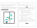
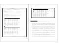
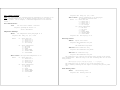
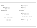
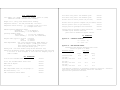
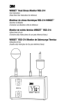
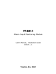
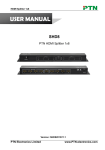
instructions for
TABLE OF CONTENTS
I.
II.
QUESTEMPo15
Area
Heat Stress
Monitor
56-070
11/97
Rev. C
1
INTRODUCTION..............................................4
FEATURES AND OPERATION....................................4
DISPLAY...............................................4
KEYPAD................................................5
CONNECTORS............................................7
III. SENSORS...................................................8
IV.
USING THE QUESTEMP°15.....................................9
V.
BATTERY REPLACEMENT.......................................9
VI.
CALIBRATION..............................................10
VII. REMOTE MONITORING........................................10
VIII. MULTIPLE SENSOR ARRAY OPERATION..........................11
INDEPENDENT MULTIPLE AREA MONITORING.................11
WBGT MEASUREMENTS WITH RESPECT TO THE TEMPERATURE
UNIFORMITY OF AN ENVIRONMENT......................11
ISO TRI-SENSOR MOUNTING RACK.........................12
IX.
ALARM....................................................13
X.
DATA STORAGE.............................................14
XI.
PRINTING DATA............................................14
SAMPLE PRINTOUT......................................16
PRINTOUT DESCRIPTION.................................17
XII. USING THE QUESTEMP°15 WITH A PERSONAL COMPUTER...........19
WAKE-UP ALARM........................................19
ASCII COMMAND SEQUENCES..............................20
Unit Identification.............................20
Temperature Readings............................20
Echo Flag Control...............................21
Check Battery Level.............................21
Date Control....................................22
Auto-Execute Buffer Control.....................22
Set Display Units...............................23
Restart Auto Execution..........................23
Get Hexdump.....................................23
Identification Codes............................23
Set Baud Rate...................................23
Keypad Echo Control.............................24
Alarm Control...................................25
Alarm Relay Control.............................25
Set No-Echo Flag................................26
On/Off Control..................................26
Printout........................................26
Custom WBGT Control.............................26
Run Mode Control................................27
Operational Status..............................27
Time Of Day.....................................27
Output User Defined Messages....................28
Print Rate Control..............................28
Wake-up Alarm Control...........................29
Auto Execute Control............................30
Timed Delay.....................................30
Unit Reset......................................30
2
Alarms..........................................30
Command Errors..................................30
RS-232C CABLE CONNECTIONS............................31
XIII. SPECIFICATIONS...........................................32
XIV. ACCESSORIES..............................................32
XV.
APPENDIX.................................................33
XVI. SERVICE AND WARRANTY POLICY..............................34
Figure 1
3
Questemp°15
4
KEYPAD
I. INTRODUCTION
The Questemp°15 is a compact, portable area heat stress monitor which
computes the WBGT index.
The WBGT index is an accepted method for
determining the heat stress level imposed on an individual in a given
environment. The Questemp°15 measures three parameters: ambient or dry bulb
temperature (DB), natural wet bulb temperature (WB) and globe temperature
(G). The WBGT index is a weighted average of these measurements according to
the formulas:
Depressing the DISPLAY key will cause the displayed
temperature
to
cycle
through
the
following
measurements: WBGT OUT (outdoor WBGT index), WBGT IN
indoor WBGT index) , GLOBE temperature, DRYBULB
temperature and WETBULB temperature. An additional measurement is WBGT
CUST (user defined WBGT index) which will have a value if the parameters
have been entered with a PC via the data port.
WBGT (indoor) = 0.7WB + 0.3G
WBGT (outdoor)
= 0.7WB + 0.2G + 0.1DB
The Questemp°15 will display indoor or outdoor WBGT as well as any of the
individual sensor temperatures used to compute the WBGT reading.
In
addition, the customer may modify the constants via a PC to create a custom
WBGT index.
Temperature may be displayed in either degrees Celsius or
Fahrenheit.
The temperature sensor array is easily removed for remote
sensing applications.
Up to 41 hours of temperature data may be stored in the Questemp°15's
internal battery backed memory. A data output port allows connection to a
serial or parallel printer or to a personal computer. An alarm temperature
may be set which allows the unit to be used for on-site monitoring. The
alarm will operate a relay which may be used to interface the Questemp°15 to
external equipment.
The Questemp°15 has a hardware upgrade available which will allow three
sensor arrays to be used for simultaneous temperature monitoring of three
different locations. These three WBGT readings may be averaged per ISO 7243
to obtain a composite index.
II. FEATURES AND OPERATION
DISPLAY
The large liquid crystal display indicates the selected temperature reading
in degrees C or F. Separate annunciators to the left of the temperature
indicate which reading is being displayed. The annunciators 1 2 3 indicate
which sensor array's reading is being displayed in a multiple sensor array
application.
The AVG annunciator indicates that the weighted average of
three sensor arrays (per ISO 7243) is being displayed for a selected WBGT
index.
The RUN indicator shows that data logging is being performed. A low battery
indicator (LOBAT) is also included.
5
This key is only active for the Questemp°15 upgraded
with the three sensor option.
Depressing the SENSOR
SET key will cause the indicated temperature to cycle
through sensor set 1, 2 and 3 as indicated on the
display. If three sensor sets are in use and a WBGT reading is being
displayed an additional parameter (AVG) may be selected using this key.
This is the weighted average of the three WBGT indices per ISO 7243:
((2*WBGT1) + WBGT2 + WBGT3) / 4 = WBGT weighted average
Refer to the MULTIPLE SENSOR OPERATION section of this manual for more
information on this measurement.
The RUN/STOP key is a toggle function which will
start and stop data storage.
The RUN annunciator on
the display indicates when the Questemp°15 is logging
data.
All data is logged at 30 second intervals.
While in the RUN mode CLOCK, PRINT RATE, ALARM, and PRINT
may be viewed but not altered.
The Questemp°15 has an internal real time clock/
calendar.
The date and time information will be
stored along with the data while in the data storage mode.
Depressing CLOCK will display the current time
in 24 hour
format. To change the time, depress CLOCK
a second time
which will cause the single minutes digit to flash. Depressing
the ARROW key will increment the value for minutes. Depressing ENTER
will store this value and cause the tens of minutes digit to flash. Use
the ARROW and ENTER keys in the same manner to select and store the tens of
minutes, single hours and tens of hours digits. After storing the time,
the display will show month and day which are set in the same way. After
depressing ENTER to store the tens of months digit the year will be
displayed which is set in the same manner. After setting the year the
display will return to the selected temperature. To simply review the time
and date depress CLOCK followed by ENTER three times.
6
The PRINT RATE key determines the time interval
between data points on the printout. The Questemp°15
stores data every thirty seconds regardless of this
setting, but the user may wish to condense the
printout. The Questemp°15 prints according to the print
rate selected at the time of printing, not that selected while storing
data.
The output data interval is programmable from 30 seconds to 1 hour.
Depressing the PRINT RATE key displays the previously selected time between
data points. To change this time depress PRINT RATE a second time which
will cause the display to flash. Depressing the ARROW key will step
through the choices .5, 1, 2, 5, 10, 15, 30 and 60 minutes. Depressing
ENTER stores this value and returns the display to temperature.
The ALARM key is used to set a threshold temperature for
a particular WBGT reading. Depressing ALARM
displays '-AL-' and the current sensor set and
WBGT index
or individual sensor reading which will
trigger the alarm.
To change these settings depress ALARM a second time. Warning:
Individual sensor alarm levels are only settable serially,
pressing alarm a second time will cause a default to WBGT OUT.
Using the DISPLAY and SENSOR SET keys select the WBGT index (WBGTOUT,
WBGTIN or WBGTCUST) and the sensor set (1, 2, 3 or AVG) for which you wish
to program an alarm. Depressing ENTER stores that information and displays
the current alarm temperature in degrees C or F. To change units depress
the °C/°F key and the temperature will be converted. To accept this
temperature depress ENTER. To change this temperature depress the ARROW
key. The tenths digit will begin flashing and its value may be incremented
by depressing the ARROW key. Depressing ENTER will store the displayed
value and cause the ones digit to flash.
Using the ARROW and ENTER
keys, program the remaining digits. Once you begin to change the
temperature the units may not be changed. The maximum alarm temperature is
199.9°C (391.8°F).
After entering the hundreds digit the display will show either "no" or "nc"
in reference to the relay contacts available at the ALARM jack. "no"
stands for normally open relay contacts which will close when the
temperature reaches or exceeds the alarm temperature. "nc" stands for
normally closed contacts which will open when the alarm temperature is
reached or exceeded. This choice allows flexibility when interfacing the
Questemp°15 with external equipment. Depressing the ARROW key will toggle
between "nc" and "no". Depressing ENTER will store your choice and return
to the temperature display. See ALARM JACK for further information.
Depressing this key causes the displayed temperature
or WBGT index to switch between degrees Celsius or
degrees Fahrenheit. The printout obtained from the data
port will also be in the selected temperature units.
Depressing the
displayed. If
printer 'Prll'
baud rate or a
PRINT key causes the baud rate to be
the Questemp°15 is set up for a parallel
will be displayed. To select a different
parallel printer,
depress PRINT a
7
second time. This will cause the display to flash, and the selection
may be changed by depressing the ARROW key. The choices are 300, 600,
1200, 2400, 4800, 9600 baud or parallel. Depressing the ENTER key
stores this selection and causes data to be sent via the data port to
a printer. While printing "Prin" will be displayed. After printing,
the temperature display will return.
During a printout depressing PRINT again will halt printing and return to
the temperature display. This may be useful for changing printout
parameters such as temperature units or sample rate. Data will be retained
in the unit and may be printed at any time. See PRINTING DATA for more
information.
The ARROW key is used to change menu selections while
programming the Questemp°15.
Depressing this key causes a menu selection to be
stored in memory. All menu selections are saved
through subsequent power ON/OFF cycles.
Depressing RESET and holding for 3 seconds clears the
data memory. The display will count down from 3 to 0
followed briefly by dashes.
Depressing ON/OFF turns on power to the Questemp°15.
Depressing and holding ON/OFF for 3 seconds turns off
power to the unit. The display will count down from
3, displaying either 3 2 1 0
or 3 2 1 ALE if the Wake-up Alarm is
enabled. Refer to Wake-up Alarm section for details. Turning the
unit off does not clear the data from memory.
CONNECTORS
The data port is a 25 pin D-sub connector which may be used as
DATA PORT
either a printer output or a RS-232C port. A parallel printer may be
connected to the Questemp°15 via a standard IBM PC to Centronics interface
cable (Quest model 056-019). The data port may be connected to a RS-232C
serial printer via a custom cable (Quest 056-922). The data port may also
be used for connection to the RS-232C port of a PC for sending data to the
PC or controlling the Questemp°15 from the PC. This is accomplished via a
custom cable (Quest 056-937).
The alarm jack connects to a set of relay contacts which are
ALARM JACK
activated if the programmed alarm value is exceeded. These contacts may be
used to alert external equipment that the alarm temperature has been
exceeded. The contacts may be programmed to either open or close when the
alarm temperature is exceeded. Refer to the ALARM KEY section for details.
8
The jack is a miniature phone type (1/8"). The relay contacts are rated at
1A, 30VDC and are isolated from the circuitry of the Questemp°15.
* THE ALARM JACK SHOULD NEVER BE CONNECTED TO AC LINE VOLTAGE (120V).
CONTROL AC LINE VOLTAGE THE ALARM JACK MUST CONTROL AN INTERMEDIATE
ISOLATED SWITCHING DEVICE. CONTACT QUEST TECHNOLOGIES FOR DETAILS.
TO
The sensor 2 and 3 jacks are part of a
SENSOR 2 AND SENSOR 3 JACKS
hardware upgrade option that will allow simultaneous monitoring of up to
three sensor arrays. The data from these arrays may be analyzed separately
or combined into a weighted average WBGT reading per ISO 7243.
This jack accepts an optional AC adapter (Quest model
AC ADAPTER JACK
056-067) to power the Questemp°15 from 115 VAC power. The jack is a
miniature phone type (1/8") and accepts 9 to 12VDC. The jack polarity is
tip positive. Use of the adapter automatically disconnects the battery.
III. SENSORS
The natural wet bulb thermometer gives an
NATURAL WET BULB THERMOMETER
indication of the effects of humidity on an individual. Relative humidity
and wind speed are taken into account by measuring the amount of evaporative
cooling taking place at a thermometer covered with a moistened wick. The
Questemp°15 uses a cotton wick immersed into a reservoir which must be kept
filled with distilled water. Ordinary tap water should not be used, as the
contaminants that are left behind after evaporation will shorten the life of
the wick and cause high readings. If the wick is discolored it should be
replaced. To replace the wick, slide the old wick and sponge off the top of
the sensor. Place a new wick over the sensor, making sure that the bottom of
the wick is down in the reservoir. Slide the sponge over the wick and into
the reservoir.
The globe thermometer gives an indication of the radiant
GLOBE THERMOMETER
heat exposure to an individual due to either direct light or hot objects in
the environment. This is accomplished by placing a temperature sensor inside
a blackened copper sphere and measuring the temperature rise. The WBGT index
is based on the response of a 6 inch diameter globe. The Questemp°15 uses a
2 inch diameter globe for a faster response time. The temperature of the 2
inch globe is correlated to match that of a 6 inch globe.
As an option, a sensor array with a 6 inch diameter globe is available.
The dry bulb thermometer measures the ambient air
DRY BULB THERMOMETER
temperature. This measurement is used in the outdoor WBGT calculation when
a high solar radiant heat load may be present.
IV. USING THE QUESTEMP°15
When making an area heat stress measurement the Questemp°15 should be placed
at a height of 3.5 feet (1.1m) for standing individuals or 2 feet (.6m) for
seated individuals in the area. Tripod mounting is recommended to get the
unit away from anything that might block radiant heat or airflow. A 1/4"x20
threaded bushing is available on the bottom of the Questemp°15 for mounting
to a standard photographic tripod. Do not stand close to the unit during
sampling.
Make sure that the wetbulb reservoir is filled with distilled water. After
adding water or placing the unit in a new environment, allow ten minutes for
the globe and wet bulb readings to stabilize.
Turn on the Questemp°15 by depressing the ON/OFF key. All segments on the
display will momentarily turn on, followed by a brief display showing the
software revision number. If the unit contains any previous run time the
display will momentarily display "dAtA". Check the display for the low
battery indicator and replace the battery if LOBAT is displayed.
If the
battery is good enough to turn the unit on but too low to run effectively,
"LbAt" will be displayed momentarily before the unit shuts down. If this
occurs, replace the battery.
Select the desired temperature display by
depressing the appropriate key. Select the temperature units by depressing
the °C/°F key. If data storage is desired, depress and hold RESET to clear
any old data from memory and then depress RUN. If the memory is not reset
the new data will be appended to the previous data until the available memory
is filled.
V. BATTERY REPLACEMENT
The LOBAT indicator on the display shows that the battery should be replaced.
When the LOBAT indicator first turns on it indicates approximately 8 hours of
life for an alkaline battery. If run with a low battery the unit will run
until the battery voltage falls to a level below which the Questemp°15 cannot
run effectively. The unit will then stop running and momentarily display
"LbAt" before shutting itself down in an orderly fashion.
The battery
compartment is located on the rear of the Questemp°15.
To replace the
battery, open the compartment by lifting one end of the cover. This will
expose the battery and connector.
Replace only with a standard 9 volt
alkaline battery (NEDA 1604A).
To retain data and clock/calendar settings it is recommended that the 9 volt
battery be left in the Questemp°15.
This is the primary memory backup
battery.
An internal lithium cell will retain the memory during battery
changes, but it is not recommended that the unit be left for long periods
without a battery. When the Questemp°15 is operated from the AC line the 9
volt battery is automatically disconnected from the circuit.
If AC line
power is removed, the power supply plug should be removed from the
Questemp°15 and the unit shut off so that the 9 volt battery can resume
primary memory backup.
VI. CALIBRATION
9
10
A calibration sensor module (Quest model 056-937) is included for verifying
the temperature accuracy of the Questemp°15.
To check the calibration,
remove the sensor assembly and plug the calibration module into the
Questemp°15.
With the unit set to read in degrees Celsius, repeatedly
depress the DISPLAY key and verify that the readings match those printed on
the module within 0.5°C.
If the readings are not within the 0.5°C tolerance, then have the unit
serviced and/or calibrated.
VII. REMOTE MONITORING
In some applications it may be desirable to have the sensors remote from the
Questemp°15. An example might be an ambient temperature environment above
the 60°C temperature rating of the Questemp°15 electronics. The sensors may
be removed from the Questemp°15 and connected via an extension cable or
cables. A 25 foot shielded extension cable is available from Quest (model
056-924). The Questemp°15 will operate with up to 100 feet of cable with no
loss of accuracy. The user should be cautioned that using long lengths of
cable in environments with a high amount of electrical noise may cause
interference.
VIII. MULTIPLE SENSOR OPERATION
INDEPENDENT MULTIPLE AREA MONITORING
An upgraded Questemp°15 with multiple sensors may be used to monitor up to
3 separate areas. Simply connect additional sensor arrays to the SENSOR 2
and SENSOR 3 jacks with remote cables. By depressing the SENSOR SET key you
can select the temperature of any one of sensor arrays 1, 2 or 3 to be
displayed. The measurement will be that selected by using the DISPLAY key.
Attempting to read the temperature of an empty sensor array jack will display
"----".
WBGT MEASUREMENTS WITH RESPECT
ENVIRONMENT (per ISO 7243 : 1989)
TO
TEMPERATURE
UNIFORMITY
When the temperature in the space surrounding a worker does not
To remove the sensor array, unscrew the knurled knobs on the top of the
array. Pull the sensor array straight up from the body of the Questemp°15 to
disengage the connector between the two. The extension cable may now be
connected between the 9 pin connector on the bottom of the sensor array and
that on the top of the Questemp°15. A 1/4"x20 threaded bushing is available
on the bottom of the sensor array for tripod mounting.
Figure 14 ASSEMBLED RACK
11
THE
12
OF
AN
have a constant value it is necessary to determine the WBGT index at three
heights corresponding to the worker's ankles, abdomen and head and perform a
weighted average on those values.
This value is displayed by using the
SENSOR SET key to select AVG and is computed using the formula:
weighted average WBGT reading.
To assemble this mounting rack refer to
Figure 3. The Questemp°15 electronics must
be mounted in the center (abdomen) position for the proper weighted average
calculation. Figure 2 shows the fully assembled mounting rack.
WBGT = (WBGThead + (2 x WBGTabdomen) + WBGTankles)/4
IX. ALARM
The Questemp°15 always assigns SENSOR 1 the double weighting.
This
calculation is only valid for 3 WBGT indices. The Questemp°15 will only
display this value if a WBGT display has been selected using the DISPLAY key
and if 3 sensor sets are connected. Otherwise, "----" will be displayed.
For further information refer to ISO 7243 :1989 (E) "Hot environments Estimation of the heat stress on working man, based on the WBGT-index".
QUEST ISO TRI-SENSOR MOUNTING RACK
The Questemp°15 has an alarm feature which will signal the user that the
environment is above a user selectable WBGT index. This threshold may be
assigned to any one of the WBGT indexes for one of sensor sets 1, 2, 3 or
average. In addition, the temperature read by any single sensor (wet bulb,
dry bulb, or globe) of any sensor set may also serve as an alarm threshold.
This feature is avail-able as a serial command only and may not be set
through the keypad.
The Questemp°15 with 3 sensor option comes with a tripod and
hardware for mounting the sensor arrays at the proper heights to
When the assigned WBGT index or sensor temperature equals or ex-ceeds the
threshold three things will happen to signal the operator:
1) The temperature display will flash, alternately
displaying the selected temperature and "-AL-"
2) The alarm relay (available via the ALARM jack) will
switch states. (i.e. if the alarm was set up to be
normally open "no" then it will switch states to close
the contacts.)
3) The following message will be sent out via the data port:
"A01 05-23-91 11:02:01 **** Temp. Alarm TRIGGERED ****"
When the assigned WBGT index or sensor temperature drops below the threshold
three things will happen to signal the operator:
1) The display will stop flashing
2) The alarm relay will switch back to its normal state,
normally open or normally closed as programmed in the
ALARM menu.
3) The following message will be sent out via the data port:
"A02 05-23-91 11:09:21 **** Temp. Alarm RESET ****"
Any assigned WBGT index or individual sensor temperature that exceeds the
alarm level will be indicated on a printout. The alarm level indicated will
be that programmed at the time of printing. CAUTION: the printed alarm level
setting may be altered prior to printing.
For details regarding programming the alarm and connecting the ALARM jack to
external equipment refer to the ALARM key, ALARM jack and ASCII COMMAND
SEQUENCES sections of this manual.
X. DATA STORAGE
perform
the Figure 15 Tri-Sensor Rack Assembly
13
14
By depressing the RUN/STOP key data storage is either started or stopped.
Data storage is indicated by the RUN annunciator on the display. Data is
stored in a sequential manner. Starting and stopping data storage without
clearing the memory simply adds the new data after the old. All data stored
is treated as one block whether or not it is time continuous. If the memory
fills, data storage stops and 'FULL' will be displayed. The RUN annunciator
will turn off indicating that data storage has stopped. Depress any key to
restore normal operation. To erase all data points, depress and hold the
RESET key for three seconds.
The display will count down from 3 to 0.
Releasing the key prior to zero will leave the data intact.
data for the three sensors (per ISO 7243) will be printed.
The printout, in the form of an ASCII text file, may be sent to an IBM
compatible PC via the RS-232C port. No special software is needed. Prior to
depressing the PRINT key on the QUESTEMP°15 type the following simple
commands at the DOS prompt:
MODE COM#: [baud],N,8,1,P <ENTER>
COPY COM#: [filename]
<ENTER>
where
A data point consists of the time and the temperatures of the GLOBE, WETBULB
and DRYBULB sensors. Data is stored every thirty seconds while in RUN. The
Questemp°15 has the capacity to store 41 hours of data for a single sensor
array. Multiple sensors, if used, will also have their temperatures stored.
This will reduce the available RUN time to 18 hours for two sensor arrays or
12 hours for three sensor arrays.
While in the RUN mode the CLOCK, PRINT RATE, ALARM and PRINT function
settings may be viewed but not altered.
The Questemp°15 with the 3 sensor option will only store data from sensors
which are connected at the time RUN is depressed.
During a RUN period,
plugging in an additional sensor will not add that sensor's data to the
printout.
Depressing RUN twice to stop and restart data collection will
activate that sensor.
#
is the number of the communications (COM) port to
which the Questemp°15 is connected. 1, 2, etc.
baud is the baud rate for which the QUESTEMP15 is
currently set.
filename is any acceptable 8 character MS-DOS filename.
NOTE: All temperature data is printed in either degrees Celsius or Fahrenheit
depending upon which mode the Questemp°15 is in at the time of printing.
A typical printout followed by a description is shown on the following pages.
XI. PRINTING DATA
A parallel or serial printer may be used to obtain a hardcopy of data stored
in the Questemp°15.
The printer is connected via the DATA PORT 25 pin
connector located on the left side of the unit. To configure the Questemp°15
for a printer type and to set the baud rate for a serial printer, refer to
the menu instructions under the PRINT KEY section of this manual.
To connect a parallel printer to the Questemp°15, use a standard PC printer
cable (Quest #056-019). Connect the 25 pin male plug to the DATA PORT and
the 36 pin Centronics plug to the parallel printer.
To connect a serial (RS-232C) printer to the Questemp°15, a special cable is
available from Quest (#056-922).
One end of this cable is labeled HEAT
STRESS MONITOR END and must be connected to the DATA PORT on the Questemp°15.
The other end is labeled RS-232C TO PRINTER and must be plugged into the
printer. The baud rate must be set the same on both the printer and the
Questemp°15.
To print data, depress the PRINT key followed by the ENTER key.
Depressing PRINT again will abort the printout.
The Questemp°15 will automatically print the data for each sensor array
present at the beginning of data storage. After printing the data for the
third array (if all three sensor arrays are present), the weighted average
15
16
SAMPLE PRINTOUT
SAMPLE PRINTOUT
QUEST TECHNOLOGIES
QUESTEMP°15 WBGT AREA HEAT STRESS MONITOR
Software Version Number: 1.9
12
SENSOR SET #3
Serial Number: KL1040001
Name:
---------------------------------------------------------------Location:
----------------------------------------------------------------
WET BULB
DRY BULB
GLOBE
WBGT IN
WBGT OUT
WBGT CUSTOM
----------------------------------------------------------------
HIGH
TEMP
----104.0
107.6
122.3
108.1
107.7
109.9
TIME
----11:53
11:53
12:03
12:03
12:03
12:03
LOW
TEMP
----103.1
107.0
112.5
106.2
107.0
108.3
TIME
----11:13
11:13
11:13
11:13
11:13
11:13
AVG.
TEMP
----103.7
107.3
118.7
107.2
107.1
109.0
WBGT_I
-----106.2
106.5
107.3
107.5
107.9
108.1
108.0
WBGT_O
-----106.0
106.3
107.1
107.3
107.6
107.7
107.6
WBGT_C
-----108.3
108.6
108.8
109.4
109.7
109.9
109.8
---------------------------------------------------------------TIME
----11:13
11:23
11:33
11:43
11:53
12:03
12:13
---------------------------------------------------------------1
2
Date: 7-APR-91
Start Time:11:13:15
3
4
Alarm Level Setting - Sensor Set #1
Print Rate: 10 minute
5
WBGT CUSTOM: 0.50 WB + 0.50 GLOBE + 0.00 DB
6
End Time:12:13:39
Total Run Time:01:00:14
WBGT OUT: 107.5 degree F
WET
----103.1
103.3
103.8
103.9
104.0
104.0
104.0
DRY
----107.0
107.2
107.3
107.5
107.6
107.6
107.5
GLOBE
----112.5
114.3
117.2
119.1
120.6
122.3
121.9
ALARM
-----
SENSOR SET #1
7
WET BULB
DRY BULB
GLOBE
WBGT IN
WBGT OUT
WBGT CUSTOM
10
TIME
----11:13
11:23
11:33
11:43
11:53
12:03
12:13
WET
----103.1
103.3
103.8
103.9
104.0
104.0
104.0
HIGH
TEMP
----104.0
107.6
122.3
108.1
107.7
109.9
DRY
----107.0
107.2
107.3
107.5
107.6
107.6
107.5
11
8
LOW
TEMP
----103.1
107.0
112.5
106.2
107.0
108.3
GLOBE WBGT_I
----- -----112.5 106.2
114.3 106.5
117.2 107.3
119.1 107.5
120.6 107.9
122.3 108.1
121.9 108.0
TIME
----11:13
11:13
11:13
11:13
11:13
11:13
WBGT_O
-----106.0
106.3
107.1
107.3
107.6
107.7
107.6
9
AVG.
TEMP
----103.7
107.3
118.7
107.2
107.1
109.0
WBGT_C
-----108.3
108.6
108.8
109.4
109.7
109.9
109.8
PRINTOUT DESCRIPTION
ALARM
-----
WET
----103.1
103.3
103.8
103.9
104.0
104.0
104.0
HIGH
TEMP
----104.0
107.6
122.3
108.1
107.7
109.9
DRY
----107.0
107.2
107.3
107.5
107.6
107.6
107.5
TIME
----11:53
11:53
12:03
12:03
12:03
12:03
GLOBE
----112.5
114.3
117.2
119.1
120.6
122.3
121.9
LOW
TEMP
----103.1
107.0
112.5
106.2
107.0
108.3
TIME
----11:13
11:13
11:13
11:13
11:13
11:13
AVG.
TEMP
----103.7
107.3
118.7
107.2
107.1
109.0
WBGT_I
-----106.2
106.5
107.3
107.5
107.9
108.1
108.0
WBGT_O
-----106.0
106.3
107.1
107.3
107.6
107.7
107.6
WBGT_C
-----108.3
108.6
108.8
109.4
109.7
109.9
109.8
17
1.
The date when the first run period occurred is shown.
2.
Start time shows when the unit was first put into the RUN mode. End
time shows when the unit was last taken out of the RUN mode. Total run
time refers to the total amount of time spent in the RUN mode.
An
asterisk will appear after the total run time if multiple run periods
took place.
3.
At the time of printing, the current alarm level settings are shown.
4.
Print rate refers to the frequency which logged data is printed. Data
is logged every 30 seconds in the RUN mode but the print rate is used to
condense the data. As an example, a 10 minute print rate would print
every twentieth set of temperature information (every 10 minutes).
5.
The WBGT custom formula is shown. The formula can only be entered into
the Questemp°15 via a personal computer.
6.
Sensor set #1 refers to the sensor rack plugged into the top of the
unit. For a standard Questemp°15 without the multiple sensor upgrade,
this will be the only sensor set of data printed out.
7.
For each sensor and WBGT index, the maximum temperature that occurred
over the entire run time is printed along with the time of occurrence.
8.
For each sensor and WBGT index, the minimum temperature that occurred
over the entire run time is printed along with the time of occurrence.
*
*
*
*
SENSOR SET #2
WET BULB
DRY BULB
GLOBE
WBGT IN
WBGT OUT
WBGT CUSTOM
TIME
----11:13
11:23
11:33
11:43
11:53
12:03
12:13
TIME
----11:53
11:53
12:03
12:03
12:03
12:03
ALARM
-----
18
9.
For each sensor and WBGT index, the average temperature over the entire
run time is printed.
XII. USING THE QUESTEMP°15 WITH A PERSONAL COMPUTER
10.
Logged data for the WET bulb, DRY bulb, GLOBE, WBGT Indoor, WBGT
Outdoor, and WBGT Custom are printed according to the print rate. An
asterisk will appear under the alarm column if an alarm condition
occurred at the corresponding time.
The Questemp°15 can communicate with a PC via an RS-232C port. All front
panel control functions as well as a few additional functions may be invoked
via ASCII commands. A special RS-232C cable is available from Quest (#056936) for connection to a PC. This is not the same as the RS-232C printer
cable.
11.
For a multiple sensor upgraded Questemp°15, sensor set #2 data is
printed.
12.
For a multiple sensor upgraded Questemp°15, sensor set #3 data is
printed.
13.
For a multiple sensor upgraded Questemp°15, the weighted WBGT averages
of each of the three sensor sets is printed. This information is useful
when measuring using the three sensor set configuration per ISO #7243.
To connect the Questemp°15 to the PC, simply plug the end of the cable marked
'HEAT STRESS MONITOR' to the data port on the Questemp°15 and the end marked
'RS-232C TO COMPUTER' to the appropriate COM port on your personal computer.
Be sure to set the baud rates to the same value on both units. Refer to the
PRINT KEY section of this manual.
To simply retrieve any stored data in the form of an ASCII text file, refer
to the section on PRINTING DATA.
WAKE-UP ALARM
The Questemp°15 has an internal clock/calendar which allows a future power ON
(automatic wake-up time) to be programmed via the RS-232 port.
When the
Questemp°15 turns on under wake-up conditions it may be programmed to perform
a sequence of tasks through the use of an auto-execute buffer. Refer to the
ASCII COMMAND SEQUENCES section for programming instructions.
An example of programming the auto-execute buffer is shown below.
Command
Comment
&E 0<cr>
clear old data from auto-execute buffer
&E 1<cr>
begin loading the auto-execute buffer
&Z<cr>
reset (clear) memory
&RT 4 0 0<cr>
start a 4 hour run period
&P<cr>
after the run, print the data
&O<cr>
turn unit OFF
&E 2<cr>
quit loading the auto-execute buffer
&W 2 3E 10 00 00<cr> set the auto-wake-up for 10:00 Mon-Fri
&X 2<cr>
enable auto-execution for wake-up mode
The above commands will cause the Questemp°15 to automatically turn itself ON
at 10:00am every Monday through Friday. It will then reset the old memory,
run for four hours, print the data, and turn itself OFF until 10:00am the
next weekday.
If the
NOTE: When turning the unit off the display counts down from 3.
display shows 3 2 1 0 it is indicating that the Wake-up Alarm is disabled.
If the display shows 3 2 1 ALE (ALarm Enable) it is indicating that the Wakeup Alarm is enabled and the unit will turn on at the programmed time.
To disable the Wake-up Alarm from the keypad, simply depress and hold down
the ON/OFF and RESET keys for the countdown.
19
20
ASCII COMMAND SEQUENCES
response: M02
NOTE: All temperature data returned from the Questemp°15 in response to an
ASCII command sequence will be in degrees Celsius and will not contain
decimal points. (As an example, a returned temperature of 345 would be
34.5°C.)
Temp [n1] [n2] = nnnn
Specify temperature to be displayed
in currently selected units
n1 = which data set
0 = sensor bar 1
1 = sensor bar 2
2 = sensor bar 3
3 = ISO average
&AS n1 n2<cr>
where:
Unit Identification:
Get unit serial number & revision.
?<cr>
n2 = which temperature
0 = wet bulb
1 = dry bulb
2 = globe
3 = indoor WBGT
4 = outdoor WBGT
5 = custom WBGT
response: Questemp°15 Version 1.3
Serial: KL1040001a
Temperature Readings:
&A<cr>
Get temperature being displayed in °C
response: M02
where:
Temp [n1] [n2] = nnnn
n1 = which data set
0 = sensor bar 1
1 = sensor bar 2
2 = sensor bar 3
3 = ISO average
n2 = which temperature
0 = wet bulb
1 = dry bulb
2 = globe
3 = indoor WBGT
4 = outdoor WBGT
5 = custom WBGT
response: M01
New Display: n1 n2
Echo Flag Control:
Report echo status
&AE<cr>
response: M29 Timed Echo Flag Set
or
M30 Timed Echo Flag Reset
&AE 0<cr> Reset timed echo flag
response: M30 Timed Echo Flag Reset
&AE 1<cr> Set timed echo flag
response: M29 Timed Echo Flag Set
&AG n1 n2<cr>
where:
Get Specified temperature in °C
n1 = which data set
0 = sensor bar 1
1 = sensor bar 2
2 = sensor bar 3
3 = ISO average
n2 = which temperature
0 = wet bulb
1 = dry bulb
2 = globe
3 = indoor WBGT
4 = outdoor WBGT
5 = custom WBGT
The timed echo flag controls the echoing every second of the sensor
array temperatures. When the flag is set the following data will be sent
every second:
M31 t[0][0] t[0][1] t[0][2] t[1][0] ..... t[2][2]
The timed echo flag is reset by any of the following: the
&AE 0 command, reseting the rts signal or turning the QT-15's power
off.
Check Battery Level:
&B<cr>
Check Battery Level.
response: M03
21
Battery Level OK
22
or
M04
Battery Level Low
Date Control:
&D<cr>
&F<cr> Get current display units
Get current Date.
response: M06
Set new Date.
where: mm = month 1-12
dd = day of month 1-31
yyyy = year i.e. 1991
response: M06
&E 1<cr>
M08
&F 0<cr>
&F 1<cr>
Display set to degrees F
&G<cr> Go to start of auto-execute file (Only functions when
autoexecuting)
M18 Execute Buffer Load Flag Reset; nn bytes used;
nn bytes free
Load following commands to auto-execute
buffer.
M17 Execute Buffer Load Flag Set; nn bytes used;
nn bytes free
Stop loading commands to auto-execute buffer.
response:
Set Degrees F.
response: M08
response: none
Get Hexdump:
&H<cr>
&E 2<cr>
Display set to degrees C
Restart Auto Execution:
Clear auto-execute buffer.
response:
Display set to degrees C
or
Display set to degrees F
Set Degrees C.
response: M07
Date: 5-23-1991
Auto-Execute Buffer Control:
response:
response: M07
Date: 5-23-1991
&DS mm dd yyyy<cr>
&E 0<cr>
Set Display Units:
M18 Execute Buffer Load Flag reset; nn bytes used;
nn bytes free
Get hex dump of logged data.
response:
(hexdump of logged data)
Identification Codes:
&I<cr>
Get unit serial number & software revision.
response: Questemp 15 Version 1.3
&E 3<cr>
Serial: KL1050002
List commands in auto-execute buffer.
&IS KL1040001a<cr> Set unit serial number
response: M21
Auto-Execute Buffer Listing:
response: Questemp 15 Version 1.3 Serial: KL1040001a
(commands in buffer)
Set Baud Rate:
M17 Execute Buffer Load Flag Set; nn
bytes used; nn bytes free
or
M18 Execute Buffer Load Flag reset; nn
bytes used; nn bytes free
&J n<cr>
Where
n = 0
1
2
3
9600
4800
2400
1200
response: none
23
24
4
5
6
600
300
Prll
Alarm control:
Keypad Echo control:
&K<cr>
Get keypad echo status.
response: M27
M28
&K 0<cr>
Keypad echo Flag Set
or
Keypad echo Flag Reset
where:
Keypad echo Flag Reset
Set keypad Echo flag.
response: M27
Keypad echo Flag Set
When the keypad echo flag is set, every time a key is pressed, its key
code will be echoed or transmitted out the serial port. This flag is
automatically reset when the Questemp°15 is powered on.
Hex
0x16
0x26
0x46
0x86
0x15
0x25
0x45
0x85
0x13
0x23
0x43
0x83
^V
&
F
å
^U
%
E
à
^S
#
C
â
reset+on/off
0x52
R
Reset Countdown 0x30+count
on/off Countdown 0x30+count
n4 = alarm relay state
0 = no (close contact to alarm)
1 = nc (open contact to alarm)
ASCII
display
clock
C/F
enter
sensors
print rate
print
reset
run
alarm
advance
on/off
3 2 1 0
3 2 1 0
n1 = which data set
0 = sensor bar 1
1 = sensor bar 2
2 = sensor bar 3
3 = ISO average
n2 = which temperature
0 = wet bulb
1 = dry bulb
2 = globe
3 = indoor WBGT
4 = outdoor WBGT
5 = custom WBGT
n3 = alarm level 0-1999
1999 = 199.9 degrees C
Questemp°15 Keypad Codes
Key
Get current alarm settings.
&LS n1 n2 n3 n4<cr> Set alarm level.
Reset keypad echo flag.
response: M28
&K 1<cr>
&L<cr>
response:
A03 Alarm Level: array= n1 sensor= n2 level= n3
contact= n4
Alarm Relay Control: allows control of alarm relay independent
of WBGT index. An actual alarm
occurrence will override this control and
cause the relay to set and reset
normally.
&M<cr>
Get relay status.
&MS<cr>
Set alarm (relay to alarm position)
&MR<cr>
Reset alarm (relay to no alarm position)
responses:(same for all &M commands)
A04 Alarm Relay Contacts Closed
or
A05 Alarm Relay Contacts Open
25
26
Run Mode Control:
Set No-Echo Flag:
&R<cr>
&N 0<cr>
echo normally
&N 1<cr>
Don't echo RS232 commands
response to both: none
&RT hh mm ss<cr> Start timed run mode. If this
command is in an Auto-execute file it will
delay the execution of the next command
until the timed run is completed.
where:
On/Off Control:
&O<CR>
Toggle Run mode.
hh = number of hours
mm = number of minutes
ss = number of seconds
Turn unit off.
response:(same for both commands)
M11 Run Mode now ACTIVE
or
M12 Run Mode now INACTIVE
response: M09 Unit will turn off when DTR is
reset
RTS signal will turn power to the unit on.
Operational Status:
Printout:
&P<cr>
Execute normal Printout.
&S<cr>
Get current Status.
response:
If the parallel interface has been selected by the keypad, the
printout will go to the parallel printer. If the serial
interface is selected, the printout will go to the serial
interface. Using a combination cable, a remote RS-232 command
can cause a printout to a parallel printer to occur.
where:
M13 Status: Run Flag= n1 Run-Time= n2 sec. Time
Left= n3 sec. Alarm Flag= n4
n1= Run Flag
0 = not in run mode
1 = Run Mode
Custom WBGT Control:
n2 = elapsed Run Time in seconds
&Q<cr>
Get custom WBGT factors.
n3 = time left in timed run mode.
&QS n1 n2 n3<cr>
Set custom WBGT factors to
define the equation
n4 = Alarm Flag
0 = no alarm
1 = alarm condition
WBGT= (n1 x WETBULB) + (n2 x DRYBULB) + (n3 x GLOBE)
where:
n1, n2, n3 = decimal fractions in
hundredths (n1, n2 and n3
need not add up to 100)
response: (same for all &Q commands)
M10 Custom WBGT: Wet= n1 Globe= n2
Dry= n3
Time Of Day:
&T<cr>
Get current time.
&TS hh mm<cr> Set new time of day.
where :
hh = hours in military time (0-23)
mm = minutes (0-59)
response: (same for both commands)
M14 Time: hrs:min:sec
27
28
Wake-up Alarm control:
Output User Defined Messages:
&U 0<cr> send null code
&W<cr>
response: null code
&U 1"string"<cr> send string minus <cr>
response: "string" no <cr>
&U 2"string"<cr> send string with <cr>
response: "string" with <cr>
Get current wake-up alarm setting
response: M22 Automatic Wake-up Disabled
or
M23 Date Wake-up Enabled for mm/dd at hh:mm:ss
&W 0<cr>
Disable wake-up alarm.
response: M22
Automatic Wake-up Disabled
&W 1 mm dd hh mm ss<cr> Set date & time wake-up
alarm.
&U 3"string"<cr> send string with <cr><lf>
where:
response: "string" with <cr><lf>
&U 4 HHH<cr> send hex data character - one hex character
only
response: hex character
mm
dd
hh
mm
ss
=
=
=
=
=
month (1-12)
day of the month (1-31)
hours in military time (0-23)
minutes (0-59)
seconds (0-59)
response: M23 Date Wake-up Enabled for mm/dd at hh:mm:ss
&U 5 n1 n2<cr> send Temp in deg C of sensor bar/ISO avg
0,1,2,3 (n1) and sensor/WBGT 0,1,2,3,4,5
(n2)
response: degree C of appropriate sensor combination
&U 6 n1 n2<cr> send Temp in deg F of sensor bar/ISO avg
0,1,2,3 (n1) and sensor/WBGT 0,1,2,3,4,5
(n2)
response: degree F of appropriate sensor combination
Print Rate Control:
&V<cr>
Get current print rate.
&VS n1<cr> Set new print rate.
where : n1=print rate
0 = 30 seconds
1 = 1 minute
2 = 2 minutes
3 = 5 minutes
4 = 10 minutes
5 = 15 minutes
6 = 30 minutes
7 = 60 minutes
&W 2 wd hh mm ss<cr> Set days of the week wake-up alarm.
where: wd = which days of the week
1 = Sunday
2 = Monday
6 3 1 |
4 = Tuesday
4 2 6 | 8 4 2 1
8 = Wednesday
|
16 = Thursday
X X X | X X X X
32 = Friday
(0-7)
(0-F)
64 = Saturday
Add these numbers and send the result in Hexidecimal to
set multiple days of the week. I.E. 05= Sunday &
Tuesday, 0E= Monday, Tuesday & Wednesday 3E= Monday
thru Friday
hh = hours in military time (0-23)
mm = minutes (0-59)
ss = seconds (0-59)
response:
&W 3 hh mm ss<cr>
where:
response: (same for both commands)
M15 Print Rate= n1
29
M24 Week Days Wake-up enabled for Days wd at
hh:mm:ss
Set daily wake-up alarm.
hh = hours in military time (0-23)
mm = minutes (0-59)
ss = seconds (0-59)
30
response:
M25
Daily Wake-up enabled at hh:mm:ss
If the QT-15 receives a command that it does not understand, it will
respond with the following message:
Auto-Execute control:
This command controls the execution of the commands stored in the auto
execute buffer by the &E commands. The bufferred commands can be
executed every time the unit is powered on, or only when powered on by
a clocked automatic wake-up alarm (controlled by the &W commands).
&X<cr>
Get Auto-execute Status.
&X 0<cr>
Disable Auto-execute
&X 1<cr>
Enable Auto-execute for all power-up.
&X 2<cr>
Enable Auto-execute for alarm wake-up only
response: (same for all commands)
M26 Enable Auto Execute = n1,
Auto Wake-only = n2
where:
Command Errors:
M99
*** Command Error ***
RS-232C CABLE CONNECTIONS
The pinout for the DATA PORT connector is shown in Figure 4. All other
pins are used for connection to a parallel printer and must not be
connected for serial operation.
When connected to a serial printer the Questemp°15 is DTE and the printer
is DCE. When connected to a personal computer the Questemp°15 is DCE and
the computer is DTE.
The data word has 8 data bits, 1 stop bit and no parity.
rate, refer to the PRINT key section of this manual.
An RTS signal will always turn power to the unit ON.
n1 = Auto Execute Flag
0 = disabled
1 = enabled
n2 = Auto Execute on Auto Wake-up Only
0 = disabled
1 = enabled
Timed Delay: During autoexcute (only functions while autoexecuting)
&Y n1 n2 n3<cr>
where: n1 = hours, n2 = minutes,
n3 = seconds
response: none
Unit Reset:
&Z<cr>
Reset (clear) logging data memory.
response: M16
Unit Reset
Alarms:
When a temperature alarm occurs, the QT-15 will send a message over
the RS-232 port if the RTS signal is present.
A01
05-23-1991
13:12:05
**** Temp. Alarm TRIGGERED ****
A02
05-23-1991
16:23:45
**** Temp. Alarm RESET ****
Figure 16 RS-232 CABLE CONFIGURATIONS
31
32
To set the baud
XIII. SPECIFICATIONS
Size: Width: 6.5" (165mm); Height: 10" (254mm); Depth: 2" (51mm)
Dimensions include a mounted sensor assembly.
SA-2 Sensor array with 2 inch diameter globe
056-941
SA-6 Sensor array with 6 inch diameter globe
056-945
RS-232C cable for serial printer (25 pin male)
056-922
Weight: 28 oz. (800 g) with mounted sensor assembly.
RS-232C cable for personal computer (25 pin female) 056-936
Temperature Sensors : 1000 ohm platinum RTD, 3.85 ohm/°C
Temperature Sensor Accuracy:
+/- 0.5 degree C from 0°C to 100°C
+/- 1.0 degree above 100°C
Ambient Operating Temperature Range:
Questemp°15
: 0 to 60 degrees C
Sensor Assembly : 0 to 100 degrees C
Parallel printer cable (36 pin Centronics)
056-019
Carrying Case for Questemp°15 and accessories
056-939
Carrying Case for QT-15M-3 3 sensor option kit
(includes tripod, brackets with rod)
056-940
Quest Suite for Windows PC support software
Operating Humidity Range:
Electronics
:
Sensor Assembly :
0 to 95% non condensing.
0 to 100% (non submersible)
XV. APPENDICES
Appendix A : CONVERSION FORMULAS
Response Time (typical): Dry Bulb : 2 minutes
Globe
: 12 minutes
Wet Bulb : 10 minutes
°C = 5/9(°F - 32)
Power Requirements : One 9 volt alkaline battery (NEDA #1604A) or
optional AC adapter. [2-3mA typical current
drain without using RS-232C, 20mA typical
while using the RS-232C port.]
Battery Life : 100 hours minimum (using RS-232C decreases life)
Effects Due To External Fields : Tested for RF susceptibility with less than
0.3°C error at field strengths to 10V/m over the frequency range of
10MHz to 500MHz.
°F = 9/5°C + 32
Appendix B : HEAT EXPOSURE TABLES
Permissible Heat Exposure Threshold Limit Values
(Values are given in °C WBGT)
Work-Rest Regimen
Work Load
Light
Moderate
Heavy
Continuous Work
30.0
26.7
25.0
75% Work 25% Rest, each hour
30.6
28.0
25.9
50% Work 50% Rest, each hour
31.4
29.4
27.9
25% Work 75% Rest, each hour
32.2
31.1
30.0
XIV. ACCESSORIES
SC-25 25 foot shielded remote sensor cable
056-924
SC-5 5 foot shielded remote sensor cable
056-944
Model 920 AC adapter
056-067
TP-1 Tripod
059-045
RWS-1 Replacement wicks (10) and sponges (3)
056-056
WB-1 Water Bottle, 2 oz.
056-068
CSM-1 Calibration sensor module
056-937
33
from "American Conference of Governmental Industrial Hygienists - Threshold
Limit Values and Biological Exposure Indices for 1990-1991"
Reprinted with permission from ACGIH
34
XVI. SERVICE AND WARRANTY POLICY
Service Policy
The Quest product you have purchased is one of the finest instruments
available. It is backed by our full one year warranty which seeks complete
customer satisfaction. This is your assurance that you can expect prompt
courteous service for your equipment from the entire Quest service
organization.
Should your Quest equipment need to be returned for repair or recalibration,
please contact the Service Department at 1(800)245-0779 (USA) or Fax
(262)567-4047 for a Return Authorization Number. The RA number is valid for
30 days, and must be shown on the shipping label and purchase order/cover
letter. If you are unable to return instruments in that time call for a new
RA number. Send it prepaid and properly packed in the original shipping
carton directly to Quest Technologies, 1060 Corporate Center Dr., Oconomowoc,
WI 53066 U.S.A.
Repair or replacement work done under warranty will be performed free of
charge, and the instrument will be returned to you prepaid. Your copy or a
photocopy of the Quest Registration Card will serve as proof of warranty
should the factory require this information.
If for any reason you should find it necessary to contact the factory
regarding service or shipping damage, please direct your calls or letters to
the attention of the Service Manager, Quest Technologies, (262) 567-9157 or
(800) 245-0779. Office hours are from 8 AM to 5 PM (Central Standard Time)
Monday through Friday.
Warranty Policy
Quest Technologies warrants our instruments to be free from defects in
materials and workmanship for one year under normal conditions of use and
service.
For U.S.A. customers, we will replace or repair (our option)
defective instruments at no charge, excluding batteries, abuse, misuse,
alterations, physical damage, or instruments previously repaired by other
than Quest Technologies. Microphones, sensors, printers, and chart recorders
may have shorter warranty periods. This warranty states our total obligation
in place of any other warranties expressed or implied. Our warranty does not
include any liability or obligation directly resulting from any defective
instrument or product or any associated damages, injuries, or property loss,
including loss of use or measurement data.
For warranty outside the U.S.A., a minimum of one year warranty applies
subject to the same limitation and exceptions as above with service provided
or arranged through the authorized Quest sales agent or our Quest European
Service Laboratory.
Foreign purchasers should contact the local Quest
authorized sales agent for details.
35