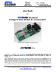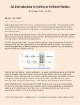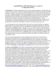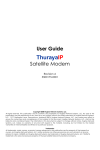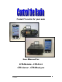
1
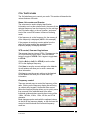
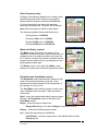
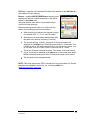
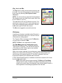
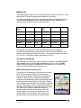
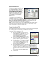
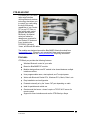
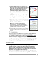
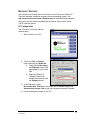
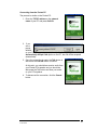
Pocket PC control for your radio
User Manual for
CTR-Remote - CTR-Rcvr
CTR-Server - CTR-BlueLync
CTR USER MANUAL -REV5
4/28/2008
1
TABLE OF CONTENTS
INTRODUCTION ........................................................................................................................................ 4
ABOUT THIS DOCUMENT ....................................................................................................................... 4
TRADEMARKS AND TRADE NAMES .............................................................................................................. 5
THE CTR SYSTEM ..................................................................................................................................... 5
CTR-REMOTE ............................................................................................................................................. 5
CTR-RCVR ................................................................................................................................................. 5
CTR-SERVER .............................................................................................................................................. 6
CTR-BLUELYNC ........................................................................................................................................ 6
NEW FEATURES ........................................................................................................................................ 7
CTR-REMOTE ............................................................................................................................................ 8
FEATURES ................................................................................................................................................... 8
INSTALLATION ............................................................................................................................................ 9
PROGRAM DESCRIPTION ............................................................................................................................10
Functions ..............................................................................................................................................10
Menus....................................................................................................................................................10
Bluetooth Options .................................................................................................................................11
CTRL TAB FEATURES .................................................................................................................................13
Name, list counter and S-meter.............................................................................................................13
VFO control, Save and Log buttons ......................................................................................................13
Frequency control .................................................................................................................................13
Car Radio Button Bar ...........................................................................................................................14
Direct frequency entry ..........................................................................................................................15
Mode and History controls ...................................................................................................................15
Resolution and Scan Mode controls .....................................................................................................15
Play, Lock, and Btn ...............................................................................................................................18
FM Options ...........................................................................................................................................18
Radio Selection and On-line Control ....................................................................................................19
On-line Polling .....................................................................................................................................19
Scan-Options Menu ..............................................................................................................................19
LOG TAB FEATURES...................................................................................................................................20
Log Editing ...........................................................................................................................................20
LIST TAB FEATURES ..................................................................................................................................21
List-Options Menu ................................................................................................................................21
List Edit Window...................................................................................................................................22
DX TAB FEATURES ....................................................................................................................................22
DX Clstr Screen ....................................................................................................................................22
Changing the DX Cluster Address ........................................................................................................23
Logging in .............................................................................................................................................23
Downloading previous activity .............................................................................................................24
Tracking and filtering ...........................................................................................................................24
DX-Option Menu ..................................................................................................................................24
Saving and Opening DX Cluster Files ..................................................................................................25
KEY TAB FEATURES ..................................................................................................................................25
Control buttons .....................................................................................................................................25
Message buttons....................................................................................................................................26
Key-Options Menu ................................................................................................................................27
Key Settings ..........................................................................................................................................27
CTR USER MANUAL -REV5
4/28/2008
2
CTR-RCVR ..................................................................................................................................................28
LEVELS ......................................................................................................................................................28
BANDSCOPE ...............................................................................................................................................29
Starting the bandscope..........................................................................................................................29
What the bandscope shows you ............................................................................................................29
Bandscope sensitivity ............................................................................................................................30
Max hold ...............................................................................................................................................30
About the bandscope .............................................................................................................................30
CTR-SERVER .............................................................................................................................................31
INSTALLING CTR-SERVER .........................................................................................................................31
UNINSTALLING CTR-SERVER ....................................................................................................................31
PROGRAM OPERATION ...............................................................................................................................32
CONNECTING FROM CTR ...........................................................................................................................32
CTR-BLUELYNC .......................................................................................................................................33
FEATURES ..................................................................................................................................................33
SPECIFICATIONS .........................................................................................................................................34
POCKET PC CONFIGURATION.....................................................................................................................34
PC CONFIGURATION ..................................................................................................................................36
REMOTE AUDIO .......................................................................................................................................36
MICROSOFT PORTRAIT ...............................................................................................................................37
PC Configuration..................................................................................................................................37
Pocket PC Configuration ......................................................................................................................38
Radio Setup ...........................................................................................................................................38
Setting up a connection .........................................................................................................................39
FUTURE PRODUCTS ................................................................................................................................41
CTR USER MANUAL -REV5
4/28/2008
3
INTRODUCTION
This user manual describes the operation of the CTR family of radio control
products produced by www.lynovation.com. These products allow the user to
control amateur radios using Windows based Pocket PCs running Pocket PC
2002, Mobile 2003, Mobile 2005, and some Mobile 6 devices (with 320x240
displays). Connections can be via direct serial, Bluetooth wireless technology,
TCP/IP (Internet), and Wifi (wireless TCP/IP).
Products include the following:
CTR-Remote – radio control software for the Pocket PC
CTR-PC – Windows based control software for the PC
CTR-Rcvr – radio control Pocket PC software for the Icom PCR1000 receiver
CTR-PCRcvr – Windows based PC control software for the Icom PCR1000
receiver
CTR-Server – serial port server software for Windows that allows CTR-Remote
to access a radio connected to a serial port on your PC over a TCP/IP network
connection
CTR-Bridge – serial port server software for Windows that allows you to bridge
multiple TCP/IP network connections to a single serial port
CTR-BlueLync – a custom designed Bluetooth serial interface for the radio that
allows you to control your radio wirelessly using the built-in Bluetooth capabilities
in your Pocket PC or PC
ABOUT THIS DOCUMENT
Several conventions are used in this document.
Pocket PC is abbreviated PPC
Bold text is used for menu names, menu paths, or button names
Example: File -> Options -> Set Time means select the Set Time option
in the Options menu in the File menu
Italics text is used for emphasis to describe programs or special features
Example: Run the CTR-Server.exe program to enable TCP/IP serial port
access.
Bold-Italics red text is used for cautions and warnings
Warning: Always ensure your transmitter is connected to a load before
transmitting.
CTR USER MANUAL -REV5
4/28/2008
4
TRADEMARKS AND TRADE NAMES
The Bluetooth word mark and logos are owned by the Bluetooth SIG, Inc. and
any use of such marks by Lynovation is under license. Other trademarks and
trade names are those of their respective owners. The CTR system
CTR products are designed to work together to fill a variety of needs for radio
control. They can also be used separately or with other programs.
CTR-REMOTE
CTR-Remote is a PPC 2002/2003/2005/Mobile 6
program written with Microsoft Visual Studio .NET.
As such, it shares many of the same attributes as
full Windows based programs. CTR-Remote allows
you to control many features of your radio with a
simple point and click interface. Regardless of the
radio selected, the program has the same look and
feel.
CTR-Remote can connect to the radio using a
direct serial connection (if supported by your PPC),
through a TCP/IP connection using CTR-Server or
another port serving device, or through a Bluetooth
connection using a CTR-BlueLync or other
Bluetooth interface connected to your radio.
NOTE: The Control and DX Clstr tabs were renamed Ctrl and DX in versions
starting with v2.04.00. Displays in this document may show either notation
depending on the version used for the screen capture.
CTR-RCVR
CTR-Rcvr is a special version of CTR-Remote
specifically written for the Icom PCR1000
wideband receiver. It contains all of the
functionality of CTR-Remote. Since the PCR1000
is a computer-controlled receiver, CTR-Rcvr also
provides control for volume, squelch, IF shift, and
DSP on a separate tab called Lev. It also includes
a basic bandscope that provides spectrum pointand-click tuning.
All of the connection methods in CTR-Remote are
available in CTR-Rcvr, including Bluetooth
(requires a special version of CTR-BlueLync)
making CTR-Rcvr an ideal solution to your
portable and mobile monitoring needs.
CTR USER MANUAL -REV5
4/28/2008
5
CTR-SERVER
CTR-Server is a Windows program
that runs on your PC that allows
you to access a serial port on that
PC across a TCP/IP connection.
This connection can be on your
local network, a Wifi network, or the
Internet, depending on your needs.
It is designed to work with all CTR
software but can also be used as a
general port server for any program
requiring access to a serial port.
CTR-BLUELYNC
CTR-BlueLync is a
custom built Bluetooth
interface based on the
BlueSMiRF Bluetooth
module from Spark
Fun Electronics.
Models have been
available for Yaesu,
Kenwood, Icom
(including the
PCR1000), and the
Elecraft K2. Currently,
only Yaesu and Icom
models are shipping.
CTR-BlueLync Keyer is
the worlds first
Bluetooth enabled keyer. This module has been discontinued due to lack of
interest.
CTR USER MANUAL -REV5
4/28/2008
6
NEW FEATURES
New features are added to CTR products as resources permit. These additions
will be documented in this section.
Program
Version
Feature
CTR-Remote
2.40.00
Added support for BlueSMiRF-Gold modules
CTR-Rcvr
1.40.00
Added support for hardware cursor buttons
CTR-PC
3.20.00
Added support for BlueSMiRF-Gold modules
CTR-PCRcvr
3.20.00
CTR-Remote
2.20.02
Added support for CTR-BlueLync and CTRBlueLync Keyer. Added “car radio” buttons
CTR-Rcvr
1.10.02
Added support for CTR-BlueLync. Added “car
radio” buttons
CTR-Remote
2.10.02
Added bandscope feature and fixed several
bugs
CTR-Remote
2.04.00
CTR-Rcvr
1.02.00
Added call sign lookup options to the File menu,
Edit Log window, and DX-Option menu
CTR-Remote
2.03.00
CTR-Server
1.01.00
CTR-Server
1.00.08
CTR USER MANUAL -REV5
4/28/2008
Added a remote PTT option. Hardware and
software PTT are supported. Hardware uses
RTS on the RS-232 port and requires additional
hardware.
Added an option to allow the serial port to
remain active when in Listen mode. This keep[s
the Icom PCR1000 radio active when CTR-Rcvr
is off-line.
7
CTR-REMOTE
By its very nature, the Pocket PC is a small device with an equally small
operating system and limited resources. The design philosophy behind CTRRemote has always been to control the radio, not manage the radio.
You won't find memory management or many radio-specific features in this
program. There are simply too many rigs on the market to make this program
compatible with all of the various features in each rig.
Therefore, CTR-Remote contains a basic set of standard commands that work
with the Yaesu, Kenwood, Icom, and Elecraft K2 radios. New models are
continually being added to the list of supported radios on the
www.lynovation.com web site.
The basic command set includes the following:
Set and read the primary VFO frequency
Set and read the radio's mode
Set the tone/DCS control coding (FM only, depends on manufacturer
support)
Set the transmit offset frequency (FM only, depends on manufacturer
support)
Read the S-Meter (depends on radio model)
Read the squelch/unsquelched mode of the radio (depends on
manufacturer and model)
FEATURES
CTR-Remote is optimized for Pocket PC/Mobile 2003/2005 devices with
integrated Wifi and/or Bluetooth connectivity. It also runs on Pocket PC 2002
devices and runs on a limited number of Mobile 6 devices. It supports direct
serial (if available), Bluetooth, and the TCP/IP connection provided by Microsoft
ActiveSync and Wifi.
Controls Yaesu, Kenwood, Icom, and Elecraft amateur radio transceivers
Direct keypad input
Supports the ADIF (http://www.hosenose.com/adif) logging format, both
import and export
Easy to use frequency list with priority scan flag
DX Cluster connections on TCP/IP and Wi-Fi with auto-tracking and save
to log features
Callsign lookup – lookup any call on QRZ.com (new in v2.04.00)
Lookup calls from the File menu or the Edit Log window
Automatically lookup DX cluster spots and display the name/QTH
NCDXF/IARU beacon scanning (www.ncdxf.org/beacons.html)
CTR USER MANUAL -REV5
4/28/2008
8
Built-in optional band plan automatically selects the correct mode for the
selected frequency
Band-spread control allows easy fine-tuning
Vocal frequency and mode announcements with auto-announce mode
History list remembers the last 20 frequencies visited
Manage CTR-BlueLync properties (new in v2.20.02)
Support CTR-BlueLync Keyer (new in v2.20.02)
“Car radio” button bar allows you to easily select 12 favorite frequencies
with the click of a button (new in v2.20.02)
INSTALLATION
CTR-Remote is installed from a self-installing CAB file. A zip file containing the
CAB files can be downloaded from http://www.lynovation.com/download_ctr.htm.
CAB files are named using the version # of the program.
Example: CTR_v24000_ARM_CABS.zip contains the CAB files for CTR-Remote
version 2.40.00.
To install the program:
1. Unzip the appropriate CAB file using WinZip. There are two CAB files
supplied. The one you need to use depends upon the version of Pocket PC
you are running.
a. If you are running Pocket PC 2002, use the ARM file
b. If you are running Pocket PC/Mobile 2003/2005/6, use the ARM4 file
2. Connect your PPC to your PC using ActiveSync. Use File Explorer or My
Computer on your PC to copy the CAB file to a folder on your PPC.
3. On your PPC, use File Explorer to select and execute the CAB file. It will selfextract the CTR.EXE file and all associated support files then install and
register them. Once the install is compete, the CAB file is automatically
deleted.
NOTE: You may get a popup window notifying you that the program you
installed may not display correctly because it was written for a previous
version of Pocket PC. Ignore this warning - it’s a Microsoft bug.
The program is now installed on your PPC. There should be a CTR icon in the
Start -> Programs menu. You will need to create a new folder (suggested name
CTR) under My Documents for your frequency lists and log files.
CTR USER MANUAL -REV5
4/28/2008
9
PROGRAM DESCRIPTION
Functions
CTR-Remote has five major functions. Each function is
on a separate tab.
Ctrl - choose your radio, connect to it and control the
frequency, mode, VFO, and scan mode.
Log - save your contacts in the ADIF compatible log
List - build custom frequency lists for any application
DX - monitors and tracks DX activity worldwide
(requires an Internet connection)
Key – supports the CTR-BlueLync Keyer module
Menus
File – the File menu offers the following options:
Log – create, load, and save log files
List – create, load, and save list files
DX Clsr – Open or save DX cluster activity log
files
Options – define regional defaults (date and
time formats), set auto-announce and set
Pocket PC time
Callsign Lookup – lookup callsign info on
QRZ.com
About – lists program information
Comm – the Comm menus offers the following options:
Com Properties - select a COM port, TCP/IP
Address (for Wifi), edit Bluetooth Options (see
below)
NOTE: When using a Bluetooth port, select the
COM port shown as the Outbound port in your
PPC’s Bluetooth Settings…Services…Serial
Port…Advanced menu.
Baud – set the baud rate or TCP/IP Port. This
rate should match the baud setting on your
radio.
NOTE: This option is not available with Roving Network Bluetooth
modules. Use the Comm…Com Properties…Bluetooth Options…Baud
listbox to set the baud on these units.
Poll Speed – sets the polling rate while the program is on-line with the
radio. Poll speed default is 350 milliseconds. You many need to lengthen
CTR USER MANUAL -REV5
4/28/2008
10
this time if the s-meter does not update consistently (some radios are
slow to report s-meter readings).
PTT Options - two PTT modes are available, Hardware and Software
o
Hardware PTT, the RTS signal on the RS-232 port is controlled by
the PTT button (additional hardware is required to key the radio)
o
Software PTT, the program sends software commands to the radio
to control its Tx/Rx mode.
Icom Address allows you to change the default address for your Icom
radio. Use this option if you’ve changed your radio’s CI-V address or you
have a radio that is not yet supported by CTR-Remote (basic commands
work on all Icom radios with the CI-V interface).
WARNING: If your connection is lost while you have the radio keyed up
with either PTT mode listed above, your radio will stay keyed until you
cycle its power (unless it has an internal PTT timeout timer).
Other Option Menus are available on each tab to allow you to set specific
options in those tabs. These menus are described under the tab they appear in.
Bluetooth Options
The Bluetooth Options menu selection in Com Properties allows you to select
and customize your Bluetooth device.
The BT Type listbox allows you to select the Bluetooth device you are using with
the program.
Generic BT Device: Use this option if you are using a hardware serial
connection, a generic Bluetooth serial interface, a CTR-BlueLync unit
with a BlueSMiRF-Silver Bluetooth module, or an original CTR-BlueAir
device. With this setting, no special configuration commands are sent
to the serial connection when initializing the port. The Bluetooth
device must be preset for the radio’s baud rate.
BlueRadios: Select this option if you are using an older BlueSMiRF
Bluetooth module in your CTR-BlueLync. This module will allow you to
set the serial baud rate on the BlueLync dynamically with the
Comm…Baud menu. These BlueSMiRF modules have FCC Type #
P00WME-C40 printed on their Bluetooth chip and their green LED
blinks once per second while off-line.
Roving Networks: Select this option if you are using a newer
BlueSMiRF-Gold Bluetooth module in your CTR-BlueLync. You
cannot set the serial baud rate dynamically on this device using the
Comm…Baud menu, instead, used the Baud listbox in this window to
save the serial port baud to flash ram. These BlueSMiRF modules
have FCC Type # T9JRN41 printed on their Bluetooth chip and their
green LED blinks twice per second when off-line.
There are four additional options available for BlueSMiRF modules:
CTR USER MANUAL -REV5
4/28/2008
11
Name – allows you to change the name of your device. This is the
name shown in the Bluetooth Browser window.
NOTE: If you change the device name you must connect to it once
before the name will update in the PPC’s Bluetooth Browser.
Baud – sets the power-up baud rate of BlueSMiRF module. Use this
to pre-set the device if you want to use it with other applications.
NOTE: You must use this control to set the baud rate on a
BlueSMiRF-Gold module.
Tx Pwr – sets the transmit power on CTR-BlueLync. For the most
battery life or if you experience shorter distance overload you can set
this below +15 dBm. This feature is only available on BlueRadios
based BlueSMiRF modules.
Pwr Src – sets the idle current consumption. Use Normal when
powered from an external supply. Use Battery to reduce idle current
from 50 mA to 2 mA. This may cause slower connection response.
This feature is only available on BlueRadios based BlueSMiRF
modules.
Press the Save to Flash button to program your settings into the flash ram in
CTR-BlueLync.
CTR USER MANUAL -REV5
4/28/2008
12
CTRL TAB FEATURES
The Ctrl tab allows you to control your radio. This section will describe the
various features of this tab.
Name, list counter and S-meter
The name area is used to display identification
information such as the selected radio, the name of the
selected frequency from the frequency list, the call sign
of a DX cluster report, or the cal, location, and power
level of the current DX beacon in Beacon Scanning
mode.
If the frequency is on the frequency list, the memory #
of the frequency is displayed (M#39 in this example).
If the program is receiving s-meter replies from the
radio the s-meter and the bar graph above the
frequency display will display the value.
VFO control, Save and Log buttons
The program has two internal VFO’s. These are not the
VFO’s provided by many radios. Click the VFO-A
button to toggle to VFO-B. Click it again to toggle back
to VFO-A.
Click the B=A (or A=B if in VFO-B) to set the other
VFO to the displayed frequency.
Click Save to save the current settings to the List tab.
An edit window will allow you to enter a name and
other information.
Click Log to save the current settings to the Log tab.
An edit window will allow you to enter other log
information.
Frequency control
There are several ways to control the frequency of the
radio. Clicking on the frequency display box will bring
up a direct entry keypad. A horizontal slider control
below the frequency display allows you to quickly move
from one end of the selected band to the other.
Individual up/down buttons provide direct tuning of the
1 MHz, 100 kHz, 10 kHz, 1 kHz, 100 Hz, and 10 Hz
elements.
Band changes can be made with the up/down buttons
on the left of the frequency display, or with the band list
control to the left beneath the horizontal frequency
scroll bar.
CTR USER MANUAL -REV5
4/28/2008
13
Depending on the Scan Mode selected, the up/down buttons on the right of the
frequency display box scroll the selected frequency, history, or frequency list
selection.
The small check box next to the horizontal scroll
frequency scroll bar turns on band-spread (fine-tuning)
mode. In this mode the horizontal scroll bar tunes the
frequency 10x the frequency step selection, just below
the Scan button (1 kHz in the display above).
The Scan button toggles the scan mode on/off. The
color and label of this button changes when scan mode
is active. Use the Scan Mode control to define the scan
mode. Other scan options are available in the ScanOptions menu.
Car Radio Button Bar
A new car radio style button bar was introduced in
v2.20.02. Clicking the blue Btn button next to the Lock
button toggles the display on and off.
The button bar can select on of 12 frequencies. Six are
assigned to VFO-A and six to VFO-B. Clicking a button
more than once will toggle the VFO selection and the
set the frequency to that VFO’s setting.
There are two ways to set a button’s frequency:
1. Click on the upper-left corner of the button to
set the button to the current frequency and
mode. The radio will move to whatever
frequency you ender in the direct frequency
input window.
2. Click on the lower-right corner of the button to change the button’s
current frequency and mode setting. The radio will not move to the new
frequency. This is a handy way to check existing programming of the
button.
NOTE: Set the radio’s mode before editing the button settings.
CTR USER MANUAL -REV5
4/28/2008
14
Direct frequency entry
Clicking on the frequency display box or editing a radio
button brings up the direct frequency entry keypad.
Simply enter the frequency and press the OK button.
For clarity frequencies are shown with and extra
decimal point between the 1 kHz and 100 Hz element.
Hint: Enter the frequency in MHz for best results
The following examples demonstrate direct entry…
Entering 5 sets to 5.000.000
Entering 1.1004 sets to 1.100.400
Entering 10.004 sets to 10.004.000
Entering 100004 sets to 100.004.000
Mode and History controls
The Mode control (far left) has two settings. If the
checkbox is checked as shown, manual mode control is
enabled and you can select the radio’s mode from the
list. If the box is cleared, auto-mode is selected and the
program decides which mode to use depending on the
pre-programmed band plan.
The History control, to the right of the Mode control,
allows you to select from the last 20 frequencies visited.
Resolution and Scan Mode controls
The Resolution control determines the frequency step
used in the horizontal frequency scroll bar. It also
determines the default resolution of the bandscope. In
this example it is set to 1 kHz.
The Scan Mode control selects the type of scan to use
when the Scan button is pressed. There are several
scan modes.
Band – scans the selected band using frequency steps
defined in the Resolution control (to the right of the
Scan Mode control)
Range – scans the range of frequencies
Range->Edit allows you to edit the Range of frequencies to scan
History – scans the last 20 frequencies visited
List – scans the frequencies on the List tab
List->Priority – scans the frequencies on the List tab that have their
Priority flag set
CTR USER MANUAL -REV5
4/28/2008
15
DX Clstr – connects to the selected DX cluster site (defined on the DX Clstr tab)
and enables DX spot tracking
Beacon – enables NCDXF/IAUR Beacon scanning and
displays the call sign, location and power of the active
beacon in the Name area.
Using the Beacon scan option is an excellent way to
monitor for band openings.
Beacon scanning can be used on or off-line (off-line
shown in this example) and works as follows:
While scanning for beacons the frequency range
is restricted to 20, 17, 15, 12, and 10 meters
Selecting one of these bands automatically sets
the radio to the beacon frequency (if on-line)
The current call sign, location, and power of the active beacon are
displayed in the Name area. Each beacon transmits for 10 seconds. First
it sends its call at 100 watts followed by four one-second key downs, one
at 100 watts, one at 10 watts, one at 1 watt, and one at .1 watts.
There are 18 beacons around the world. The current 10-second interval
(out of 3-minutes) is displayed in the Note area. In the screen shot above,
KH6WO transmits during the 0:30 to 0:40 second interval on 20 meters.
The key down times are approximate
NOTE: This mode requires the PPC’s internal clock to be accurately set. Several
programs are available to do this for you, including vxUtil from
www.cam.com/vxutil_pers.html
CTR USER MANUAL -REV5
4/28/2008
16
Scope – enables the bandscope feature (new in v2.10.02). This mode is
somewhat slow due to the slow s-meter response but may be of some use for
monitoring band activity.
There are a few things to know about the bandscope:
1. The resolution of the scope is determined by the Resolution
control.
2. The frequency of the main display is the center frequency on the
scope.
3. The current frequency being scanned will be shown in the Name
area of the display.
4. Clicking on a signal on the scope will automatically move the
scope center to that frequency and pause the scan for the Scan
Pause setting (in the Scan-Options menu).
5. There are two option buttons at the right of the scope.
a. Clicking the top button (-) turns on the Peak Hold feature
(^). The highest signal received at each frequency will be
held on the display.
b. Clicking on the bottom button (*) turns on the Zoom
feature (Z). In this mode, the resolution is increased by a
factor of 10 so the scope scans the band faster.
Cursor & radio
frequency
Scope center
frequency
Scan resolution
Scope display
Peak Hold
button
Peak Hold
button
CTR USER MANUAL -REV5
4/28/2008
17
Play, Lock, and Btn
The Play button vocally announces the frequency and
the mode. You can set the program to auto-announce
these values by selecting File->Options->AutoAnnounce.
NOTE: You can record your own audio announcement
files. Simply record new .WAV files for each .WAV file in
the CTR folder on your PC.
The Lock button locks all CTR-Remote controls. This
permits you to carry your PPC in your pocket and not
worry about changing program parameters. Click the
Lock button again to unlock the controls.
The Btn button toggles the car radio button bar.
FM Options
A special set of options is available when FM mode is
selected. These options allow you to set the Transmit
Offset and tone coding options.
The Transmit Offset is entered into the Tx Offset box
on the left and is entered in MHz.
NOTE: Tx Offset is not supported on all radios.
The Tone Mode option box (middle) allows you to
select the tone option to use. The options are None,
Tone Encode (T-Encode), Tone Encode and Decode
(T-Enc/Dec) and DCS. Which options are available
depends on the radio model.
When a tone mode is selected, the tone frequency selection list box (on the right)
allows you to choose the tone frequency. This option sets both transmit and
receive tones to the same frequency if T-Enc/Dec is selected. Only tone
frequencies available on the selected radio are shown.
If DCS (Digital Coded Squelch) is available and selected, choose the DCS code
from the right-hand list box.
NOTE: Most radios do not support reading Tx Offset and Tone Mode
settings from the radio. Therefore, the options listed above only set the
modes on the radio. When first displayed, they will have default values in
them regardless of the settings programmed into the radio.
CTR USER MANUAL -REV5
4/28/2008
18
Radio Selection and On-line Control
Radio selection is done by first selecting the
manufacturer then the model.
Kenwood and Elecraft radios do not have a Model list.
Kenwood radios contain an ID# so the program can
determine the model # automatically and the K2 radio is
the only radio supported in the Elecraft line.
NOTE: Selecting an Icom model sets the radio address
to the default value. You can override this value in the
Comm->Icom Adrs menu if needed.
Once you have selected the correct radio, click the Online box to begin polling the radio. Once on-line, the
VFO buttons above the frequency display will be visible.
Warning!
Make sure you select the correct model. Certain commands on some
models may lock up other models requiring you to either remove
power from the radio and/or reset it to its factory default values.
On-line Polling
The Polling Speed in the Comm menu sets the rate at which the program polls
the radio for changes. The default is 350 milliseconds. You can increase this
value if you find the s-meter does not update or the polling adversely affects the
operation of your radio. Decreasing this value does not affect the actual polling
rate since the program takes about 250 milliseconds to update between polls.
NOTE: Not all radio protocols support s-meter. If the program does not update
the s-meter graph, check your radio’s documentation to see if it supports the smeter. If it does, you may need to adjust the Polling Time in the Comm menu.
Scan-Options Menu
The Scan-Options menu allows you to control how the
program reacts in Scan mode.
Scan Speed sets the scanning rate
Scan Pause sets the amount of time the program waits
in Pause mode
Unsqueched determines if Scan pauses for the Scan
Pause time, holds, or stops when it detects the radio is
unsquelched.
S-Mtr determines if Scan pauses for the Scan Pause
time, holds, or stops when the s-meter is equal to or
greater than the S-Mtr >= the trigger threshold, also set
in this menu.
In the example display, the scan speed is 500 milliseconds and it will pause for 5
seconds if the s-meter is >= 6.
CTR USER MANUAL -REV5
4/28/2008
19
NOTE: These options may not work on all radios since not all radios support smeter reads or squelch status.
LOG TAB FEATURES
This tab provides a basic logging tool to track your
QSOs. Log files are saved in ADIF format so they are
compatible with all major PC logging programs. ADIF
formatted files can also be loaded directly into CTRRemote, but be aware that critical information may be
parsed out of them and not resaved.
The intent of the CTR-Remote log is not to replace your
current logging software. Rather, to provide a
convenient method to log contacts while portable or
mobile (when parked of course!).
The log supports the following parameters…
QSO Date and Time
(UTC)
Call sign
Contest ID
Frequency
Mode
Contest Tx SN
Power
RST-Sent
Contest Rx SN
QTH
RST-Received
Four user
selectable fields
Name
Comments (QSO notes)
QSL-Sent
QSL-Received
Log Editing
The Log-Options menu allows you to Add, Edit, or
Delete an entry. Selecting Add or Edit brings up the log
edit window where you can enter specific contact
information.
When finished editing click the OK button. To exit
without saving your changes click the Cancel button. To
delete the current selection, click the Delete button. To
move to other entries in the log, use the Left/Right
Arrow keys. To save the current entry without exiting
the edit window, click the Apply button.
Hint: Clicking the yellow [*] button next to the Dt/Tm
(Date/Time) or Freq boxes updates that data to the current value. Clicking the [*]
button next to Call will lookup the call in the QRZ.com database and display the
results. You can choose to import the name and QTH data from the lookup into
your log entry.
Note: You can add or edit a log entry from the Log-Options menu or by clicking
the Log button on the Ctrl tab.
CTR USER MANUAL -REV5
4/28/2008
20
LIST TAB FEATURES
The List tab allows you to manage custom frequency
lists. Any number of frequencies can be added to the
list, but a practical limit is around 200 entries due to the
speed of the file system.
Each entry is associated with a Memory #. M#nn is
displayed on the Ctrl tab above the s-meter when a
frequency is selected on the list.
List-Options Menu
The List-Options menu provides a number of options
for controlling the list.
Toggle Priority toggles the scan priority flag
associated with the selected memory
Priority allows you to select or clear all flags
Sort by sorts the list by name, receive
frequency, or receive mode
Add inserts a new entry to the bottom of the list
Edit brings up the List Edit window so you can
edit the current selection
Delete allows you to delete the current selection
Track Selected, when checked causes the radio to follow the selected
memory on the list. This allows you to easily check for activity on each
entry by simply clicking on it.
Note: The background color of the list turns from white to light
blue, as shown above, when Track Selected is enabled.
Save Scan Activity, when selected automatically saves any activity
found during scanning to this list.
CTR USER MANUAL -REV5
4/28/2008
21
List Edit Window
The List Edit window provides an easy way to create or
update the parameters for each list entry.
The Edit dropdown list at the top allows you to select
another entry without leaving this window. Use the
Apply button to save your changes without exiting.
If you are on-line with your radio, the ->Radio button will
be visible. Click this button to immediately download
these settings to your radio.
Note: The TxOffset, TnType, and Tone options are only
available in FM mode.
DX TAB FEATURES
DX cluster servers provide an on-line resource for DX chasers and casual
listeners. Hams around the world post DX spot messages to their local DX
cluster server and these messages are broadcast to others that are monitoring
the cluster network. For an in-depth discussion on DX cluster technology and to
download a user manual visit www.ab5k.net/Home.aspx
CTR-Remote provides a Telnet connection to most DX clusters. The program
has several servers pre-programmed into the Adrs list and you can add
additional servers for your local area.
DX Clstr Screen
The DX cluster display consists of several controls and
a window to display text.
The call sign that you logged in with is displayed in the
Call window. This is the call that will be sent to the DX
cluster when you log in. You can change it here, but
you must enter a registration key for the new call to
enable full program operation. Unregistered programs
are limited to three log, list, and DX cluster spots, and
five minutes of on-line connection time. You can obtain
a registration key from www.lynovation.com.
CTR USER MANUAL -REV5
4/28/2008
22
Changing the DX Cluster Address
The Adrs list control allows you to choose from one of
the pre-programmed DX cluster servers. You can Add
additional addresses, Edit the selected address, or
Delete the selected address by clicking and holding the
dropdown arrow on the Adrs control. This brings up a
popup menu with these options.
Server addresses can be either IP formatted (example:
127.0.0.1) or URL formatted (example: k7ar.net).
NOTE: The standard Telnet port is 23. Most
servers use this port, however some, such as
k7ar.net use other ports. To use a non-standard
port, enter it after the address, using a colon to separate it (example:
k7ar.net:7300 connects to k7ar using port 7300).
Once you select an address, click the Connect button to connect to the server.
NOTE: You must have a TCP/IP connection to the Internet for the DX
cluster option to work. This connection can be provided by the ActiveSync
connection between your PC and your Pocket PC, a dial-up modem, a
network interface card (NIC) in your Pocket PC, or by a Wifi wireless
connection.
Logging in
Once connected, the text window will begin to fill with
the information from the server. The program will
automatically send your call when the server asks for it.
If this is the first time you’ve logged into the DX cluster
network, you will be asked for additional information.
You can use the Tx and Send controls to enter and
send data to the server. Use the vertical scroll bar to
scroll the text window up and down.
NOTE: You may find it easier to Telnet into the
DX cluster server using your PC to set up your
initial information. This only needs to be done once.
There are many pre-programmed messages in the Tx control. Select the
message you want, or enter your own data the click the Send button to send it to
the server.
NOTE: You can edit, add, or delete messages like the Adrs control by
clicking and holding the Tx control’s down arrow button until the popup
edit menu appears.
CTR USER MANUAL -REV5
4/28/2008
23
Downloading previous activity
If you select the Get Previous Spots option in the DX-Options menu the last 10
DX spots will be downloaded when you connect. This allows you to check current
band conditions just by connecting.
Tracking and filtering
To set the program to automatically track DX spots on
your radio, check the Track DX on box. As spots
appear, the frequency will be sent to the radio.
NOTE: Clicking on any DX spot will
automatically download that spot’s frequency to
the radio if the program is on-line with your
radio. A DX spot line starts with DX de followed
by the reporting station.
You can set a filter to filter which band or range you
want to display in the text box. This is a local filter and
does not set the cluster server’s filter. The DX cluster
server has many more filter options so use them for
advanced filtering.
To clear the text box data, click the Clr button on the right. This will not affect
radio settings.
DX-Option Menu
There are five options in the DX-Option menu.
Get Previous Spots sends the SHOW/FDX command
to the server. This command tells the server to
download the most recent spots as formatted text. If you
check this menu item, the program will automatically
download previous spots each time you connect.
Radio Diagnostics is a special menu option that
captures and displays the control commands between
the program and the radio. This option is used to
diagnose software and control problems. You can also
use it to determine if the program is actually
communicating with your radio. Each message will be
labeled either TX (to the radio) or RX (receive from the
radio). The messages will be in the native format the radio uses.
Add Whitespace adds a blank line between each DX spot for easier reading.
Save to Log allows you to save the currently selected spot to the log. This option
is only available when you have selected a valid DX spot on the list.
Auto Call Lookup when selected automatically looks up the name and QTH of
the selected DX spot and displays it in a window at the top of the DX display. If
there is valid lookup data when you click Save to Log, that information will be
automatically entered in the Name and QTH fields of your log.
CTR USER MANUAL -REV5
4/28/2008
24
Saving and Opening DX Cluster Files
The File->DX Clstr menu allows you to save the information in the DX Clstr text
box to a text file on your Pocket PC. This option is usually used with the Radio
Diagnostics option to capture radio control activity for diagnosis.
Once the Save DX Clstr File is enabled, the DX Clstr text box changes to a light
red color indicating that data is being save to a file. To turn saving off, select File>DX Clstr-Save DX Clstr File again.
You can edit these files to create a custom DX spot file then use the File->DX
Clstr-Open DX Clstr File to load them back in.
KEY TAB FEATURES
The Key tab provides support for the CTR-BlueLync
Keyer Bluetooth enabled keyer. This keyer is based
on the K1EL WinKey IC chip and provides both the
functions of both a conventional electronic keyer and a
keyboard/contest keyer.
The Key tab has several areas of interest. The output
display at the top shows the last characters sent by the
keyer. The display just below shows characters in the
input queue waiting to be sent to the keyer.
NOTE: The CTR-BlueLync keyer is no longer
produced (due to lack of interest). I thought it was cool!
Control buttons
The first row of buttons provides the following
functions:
Click Log to jump to the Log Edit window to
add a new entry to the log. Use the Hold
button in the Log Edit window to return to this
tab.
Click Pause to halt the key queue output so
you can use the paddles to send characters.
Click it again to resume queue output.
Click the Clear button to clear the key queue in
the keyer. This immediately stops transmission.
Click the Tune button to key your transmitter. Click it again to stop
transmitting.
Click the Edit checkbox to enable one-click editing of the message
buttons.
Use the speed dropdown list to set the keyer speed.
CTR USER MANUAL -REV5
4/28/2008
25
Message buttons
Message buttons allow you to easily pre-program
message exchanges.
Rpt resends the last message
There are six general purpose messages, M1
to M6
CQ1 and CQ2 provide to CQ messages
Call sends the Call in the current Log Entry.
Click the Log button to set this entry.
de Me sends de then the call sign you entered
when you registered the program
Strt sends the initial QSO start message
RST sends the programmed message followed by the RST-S value
entered into the Log Entry. Click the Log button to set this entry.
QTH must be programmed to send your QTH
Name must be programmed to send your name
Brag can be programmed to send your rig, antenna, wx, etc. info
Bk2U is programmed for the “back to you” exchange
CT1 and 2 can be programmed with contest exchanges
Tx# automatically sends the Tx SN in the current Log Entry. Click the
Log button to set this entry.
Click the Edit button to enable on-touch message
editing. Messages that can be edited will turn yellow
when editing is turned on.
The keyboard is optimized for Morse code. Click a
character to enter it into the transmit queue.
Special Morse characters are provided at the bottom
of the keyboard.
Three keyboards are provided and are set in the KeyOptions menu.
Blue with white letters
White with blue letters
Standard Pocket PC
CTR USER MANUAL -REV5
4/28/2008
26
Key-Options Menu
The Key-Options menu provides access to several
keyer functions.
Edit Msgs allows you to edit the message
buttons
Tx File… allows you to select a text file in the
Pocket PC to transmit. Great for practice
sessions.
Settings brings up the Keyer Settings window
Keyboard1, 2, PPC Keybd allows you to select
the keyboard image.
Key Settings
Selecting Key-Options…Settings opens a WinKey
configuration window. Here you can select the following
options:
Mode – select Iambic A, Iambic B, Ultimatic, or
VibroBug mode
Output – select how the keyer outputs are
handled.
o P3=Key, P5=PTT
o P3=Key, P5=Tone
o P3=Key, P5=Off (default)
o P3=0ff, P5=Key
Sidetone – sets the sidetone frequency for the
P3=Key, P5=Tone option. An external speaker
must be connected to the P5 output for this to work.
FarnsSpd – sets the Farnsworth spacing
Swap Paddle – swaps the left/right paddle inputs
AutoSpace – automatically adds a space
CT Spacing – sets the keyer for contest spacing
CTR USER MANUAL -REV5
4/28/2008
27
CTR-RCVR
CTR-Rcvr is a special adaptation of CTR-Remote specifically written for
wideband receivers such as the Icom PCR1000.
At the present time, the PCR1000 is the only radio supported by this program.
Other radios may be added as time permits.
The program features most of the functionality of the CTR-Remote program.
Since the PCR1000 is a computer-controlled radio, CTR-Rcvr also allows you to
set several controls.
Review the CTR-Remote section for a description on the basic features of this
program. Only the additional features will be described here.
LEVELS
The Lev tab is new in CTR-Rcvr. This tab contains the
controls for the radio. From here you can set the
volume, squelch, IF shift (LSB, USB, or CW modes
only) and control the DSP features (if the UT-106 DSP
module is installed). Additional controls for AGC, Noise
Blanker, Attenuator, and AFC are also found on this
tab. You will also find a DTMF decoder here.
Control, mode, and frequency settings are saved
when you exit the program.
The relative positions of the Volume, Squelch, IF, and
DSP controls are displayed on the Ctrl tab by four
bars next to the filter list box.
CTR USER MANUAL -REV5
4/28/2008
28
BANDSCOPE
The bandscope in CTR-Rcvr is much faster and more useful in CTR-Rcvr. This is
because the PCR1000 provides better support for this option.
The bandscope display provides a visual representation of the band activity. Its
nominal bandwidth depends on the selected frequency step. Bandwidth and
resolution at each step is shown in the chart below.
Frequency
Step
Bandwidth
Res
Frequency
Step
Bandwidth
Res
10 Hz
2 kHz
High
8.33 kHz
400 kHz
Med
100 Hz
20 kHz
High
9 kHz
400 kHz
Med
1 kHz
200 kHz
High
10 kHz
400 kHz
Low
2 kHz
400 kHz
High
12 kHz
400 kHz
Low
5 kHz
400 kHz
Med
15 kHz
400 kHz
Low
6.25 kHz
400 kHz
Med
20 kHz
400 kHz
Low
As a general rule of thumb, the lower the frequency step, the higher the
resolution but the slower the scope updates. 10 kHz is recommended for fast
updates when sweeping the band for activity. Once traffic is located, shift down
to 1 or 2 kHz. To fine-tune a signal, shift down to 100 Hz.
Starting the bandscope
The bandscope is treated as a scan mode and is included in the Scan Type list.
Select Scope from the list the click the Scan button to turn it on. The Scan
button’s label will change to SCOPE while the bandscope is on. Other scan
modes are disabled while the bandscope is on.
What the bandscope shows you
The center of the bandscope is the frequency shown in
the CTR-Rcvr frequency display. The bandscope
displays a broad “picture” of the spectrum around that
frequency. Signals in this passband are displayed
vertically on the bandscope display. Signals with higher
receive levels are shown higher on the graph. Signals
with modulation will be spread out and occupy a greater
portion of the display. You can easily tune the radio to
any signal on the scope by simply clicking on the signal.
The radio may not switch to the exact frequency
because of the resolution of the display. Once the
scope updates, if the signal is not centered on the
center marker, click on it again. Once centered you
should be able to hear the traffic on that frequency.
CTR USER MANUAL -REV5
4/28/2008
29
Normal tuning modes can also be used to move the center frequency of the
bandscope.
NOTE: The PCR1000 radio does not support LSB, USB, and CW modes in
bandscope mode.
Bandscope sensitivity
The bandscope is set by default to its most sensitive
position so strong signals may go off the display. To
adjust the sensitivity, move the vertical scroll bar on
the left of the scope to a higher position. This will decrease the scope sensitivity
and bring strong signals back within range.
Max hold
You may wish to capture bandscope activity over a
period of time. To do this, click the green button on
the right of the bandscope. It will turn red as will the
bandscope signal. In this mode the scope will capture
and hold the highest level it detects at each step. Click the Max Hold button
again to return to the normal display.
About the bandscope
The bandscope is not a precision instrument. Neither the vertical or horizontal
axis’ are calibrated. It is intended as a tuning aid not a spectrum analyzer. Even
so, once you use it you will find that you won’t want to tune your radio without it
turned on.
CTR USER MANUAL -REV5
4/28/2008
30
CTR-SERVER
CTR-Server is a serial port server program. It runs on your PC and makes that
PC’s serial ports visible on a TCP/IP network connection. The network
connection can be provided by your local area network (LAN), a wide-area
network (WAN) such as the Internet or by a wireless network (Wi-Fi). Microsoft’s
ActiveSync, which ships with all Pocket PC’s, also provides a TCP/IP connection
to your Pocket PC without any other network hardware.
INSTALLING CTR-SERVER
CTR-Server is written in Visual Basic 6.0 and comes with an installation program
called Setup.exe that will step you through the installation process.
To install CTR-Server:
Download the latest installation package from the
www.lynovation.com web site.
NOTE: The version number is embedded in the file name (i.e. CTRServer_v10101.zip contains CTR-Server v1.01.01)
If an Install option is provide by your unzip utility, click this button to
install the program. If not, unzip all the program files to a temporary
folder then execute the Setup.exe file in that folder.
Follow the prompts to install the program. It is recommended that you
use the default settings to install the program.
The install program will create a new group in your Start->All
Programs menu called CTR. This group will contain the CTR-Server
shortcut.
HINT: To automatically start CTR-Server when you boot your PC,
copy the CTR-Server shortcut from the CTR group to the Startup
group.
UNINSTALLING CTR-SERVER
Should the need arise to remove CTR-Server from your PC, remove it using Add
or Remove Programs in the Control Panel.
CTR USER MANUAL -REV5
4/28/2008
31
PROGRAM OPERATION
CTR-Server is simple to use. First, set
the Connection Status to Off-line.
Next, select the COM port on your PC
from the Com Port menu and set its
serial properties. Checking RTS or
CTS sets those signals active on the
COM port if you need them. Finally,
select Listen on the Connection
Status control.
The program is now listening for a
connection request from CTR-Remote
or CTR-Rcvr at the indicated Host IP Address on the selected Host IP Port.
NOTE: The Host Name and Host IP Address are automatically set by the
operating system and cannot be changed in CTR-Server.
HINT: It is recommended that you leave the Host IP Port set to 50000. This is
outside the commercial application range of ports. You can change it to any
value under 65355, but do not set it below 1024.
CONNECTING FROM CTR
Once CTR-Server is in listen mode, connect your radio to the selected COM port
on your PC and set up a connection in CTR-Remote or CTR-Rcvr.
To set up a TCP/IP connection in CTR:
Click on the Comm menu and select the
Com Properties or Host Adrs menu. The
menu displayed depends on the current
comm configuration of the program.
Enter the Host IP Address shown in CTRServer and click OK. The Comm menu will
change to reflect the TCP/IP parameters.
The Host Port on CTR will default to 50000.
If you changed the Host IP Port on CTRServer, reselect the Comm menu in CTR
and enter the new Host IP Port.
Click the On-line check box in CTR and the program will connect to
the radio using the TCP/IP connection. The Connection Status in
CTR-Server will change to On-line and the graphic animation will
indicate two-way communications between the PC and the Pocket
PC.
To go off-line, uncheck the On-line box in
CTR-Remote.
CTR USER MANUAL -REV5
4/28/2008
32
CTR-BLUELYNC
CTR-BlueLync is a custom
radio serial interface
utilizing Bluetooth wireless
technology that allows you
to control your radio using
the built-in Bluetooth
capabilities of your Pocket
PC (or any PC, Palm, or
Mac with a radio control
program that supports
Bluetooth). No special
serial port cables or
adapters are required for
your Pocket PC and most
Icom (including the
PCR1000), Kenwood,
Yaesu, and Elecraft K2 radios.
The module was designed around the BlueSMiRF Bluetooth module from
www.sparkfun.com. Currently, only assembled Yaesu and Icom units are
available. Visit our web site, www.lynovation.com for pricing information.
FEATURES
CTR-BlueLync provides the following features:
Wireless Bluetooth control of your radio
Based on BlueSMiRF RF module
Modular design allows one RF module to be shared between multiple
interface modules
User programmable name, start-up baud, and Tx output power
Works with Bluetooth Pocket PC’s, Windows PC’s, Mac’s, Palm’s, etc.
Easy installation and configuration
Powered externally or by the Yaesu CAT port depending on radio
Ideal for portable and mobile use
Great around the house – doesn’t require a TCP/IP Wi-Fi server for
remote control
Support for future interfaces such as the CTR-BlueLync Keyer
CTR USER MANUAL -REV5
4/28/2008
33
SPECIFICATIONS
Bluetooth module
BlueRadios – Class 1
Input voltage
5 to 14 VDC
Tx/Rx current max
8 mA idle, 35 mA connected (typical)
Frequency Band
2.4 GHz
Output power
+15 dBm max
Baud Rate
1200 to 38.4K baud
Antenna
Integrated chip-antenna or external
antenna (optional)
Interface Level
Icom CI-V, Kenwood and Yaesu TTL,
Elecraft K2 and PCR1000 RS232
Certifications
EN, FCC, SIG
Temperature
-30°C to +70°C
POCKET PC CONFIGURATION
To configure the CTR-BlueLync interface to operate with your radio and your
Pocket PC, follow these setup steps.
1. Verify that your radio and the interface are setup with the same baud rate.
NOTE: The Baud Rate setting in CTR-Remote/CTR-Rcvr determines the
baud rate of the serial port connected to your radio. They should match.
2. Plug the interface into your radio and apply external power (if required). The
green LED should flash indicating the interface has power and is in Listen
mode.
3. On the Pocket PC, turn the Bluetooth radio on. This
is usually done in the Settings -> Connections ->
Bluetooth -> Bluetooth Settings program. You will
also set the Accessibility and Services options
here.
CTR USER MANUAL -REV5
4/28/2008
34
4. Under the Accessibility tab, select the options
shown at the right.
5. Under the Services tab, select the Serial Port
service and check all the Service Settings boxes.
6. Click the Advanced... button on the Services tab
and note the Outbound COM Port assignment.
This is the COM port you will select in CTR-Remote
to connect to the CTR-BlueLync interface.
If you always want to use this device for this COM
port, uncheck the option box.
7. In CTR-Remote Comm menu, select the Outbound
COM Port shown in the Bluetooth Settings window
above. The Baud rate can be set to any value since
its not used on the Bluetooth port.
CTR USER MANUAL -REV5
4/28/2008
35
8. Click the On-line checkbox in CTR-Remote. The
Bluetooth Connection Wizard should open as shown
to the right. Your display should show your CTRBlueLync by the name that you chose in the
Comm..Port Properties…Bluetooth Options menu
(“Internal” in this example). If your interface is not
shown, click the Refresh button at the bottom of the
display.
NOTE: The interface will appear as a Pocket PC
icon with a question mark as shown because the
operating system doesn’t know what type of device
it is.
9. Click on the icon for your interface. If the Bluetooth
Authentication window appears, enter default as the
Passkey and click the OK button.
NOTE: You only need to authenticate the
connection once. This creates a paired device
relationship between your Pocket PC's Bluetooth
interface and the CTR-BlueLync interface.
10. If everything is running correctly the red LED on the
interface will light and you will be returned to CTRRemote.
PC CONFIGURATION
Many people ask if the CTR-BlueLync is compatible with standard Bluetooth
enabled desktop and notebook PC’s. The answer is a qualified yes!
The only cravat is that the program you want to run must be Bluetooth aware.
Most new programs can recognize the Bluetooth virtual port and utilize it.
You must run the Windows XP SP2 and the Bluetooth adapter you are using on
your PC must be on the supported device list for the Microsoft stack. You can
check your device at http://support.microsoft.com/kb/841803/EN-US/
REMOTE AUDIO
Although CTR-Remote and CTR-Rcvr don't directly support remote audio to and
from the radio, there are free programs available that do. One program we have
found that works well, is easy to setup, and has two-way audio capability is
Microsoft Portrait. This neat little program not only provides two-way audio
between your Pocket PC and your PC, but it has less than a second buffering
delay on the audio and supports video streaming too.
For the purposes of CTR-Remote, the only the audio setup will be discussed
here. Feel free to experiment with the video streaming, SSTV via Wi-Fi anyone?
CTR USER MANUAL -REV5
4/28/2008
36
MICROSOFT PORTRAIT
First, download and install Microsoft Portrait on you PC and your Pocket PC.
There are separate installation programs for each operating system. Visit
http://research.microsoft.com/~jiangli/portrait to download these programs.
Once you have the software installed and configured, they act as a simple
TCP/IP intercom system.
PC Configuration
The PC version of Portrait requires
minimal setup.
1. Start Portrait on your PC
2.
Select the Tool -> Options...
menu and select the Audio tab
a. Verify that the Recording
and Playback settings are
appropriate for your sound
card
b. Select the GSM 6.10
(13Kbps) Codec if not
already selected and close
the Options window
3. In the Call menu, select
Reconnect After Time Out to reconnect after a network dropout and
Automatically Accept Calls so you can reconnect remotely if needed.
4. Leave the program running on your PC.
CTR USER MANUAL -REV5
4/28/2008
37
Pocket PC Configuration
The Pocket PC version is also simple to setup.
1.
Start Portrait on your Pocket PC.
2. Select Tools -> Options... and click on the
Audio tab
a. Select GSM 6.10 (13Kbps), Half-duplex
b. Select either Press and talk or Click to
talk depending on your preference. This
selects the audio transmit feature for
normal PTT or Click On/Click Off PTT.
Close the Options window.
3. In the Call menu, select Reconnect After Time Out to reconnect after a
network dropout and Automatically Accept Calls.
Radio Setup
The simplest way to connect your radio receiver is to simply plug the speaker
output into the Line-In port on your PC. This will get you connected with minimal
effort. Connecting the transmit audio from the PC to your mic input on your rig
will take a little more effort, but is well documented on other web sites and in
several magazine articles.
CTR USER MANUAL -REV5
4/28/2008
38
Setting up a connection
Connecting from the PC
To set up a connection between the PC and Pocket PC Portrait programs, initiate
a call from either program to the other.
1.
On version 2.3 of the program,
the PC program can call the
Pocket PC by entering the Pocket
PC's name in the call list and
clicking Call.
2.
Once the Pocket PC receives the connect
request, it will display a connection request
window. To accept the call, press Call-OK. If
you chose the Automatically Accept Calls
option on the PPC, the call will be accepted
automatically.
3. Once the connection is made, the Talk button is
active and the Call-OK button is inactive.
At this point, you should hear receive audio from
your Pocket PC's speaker and you should be
able press the Talk button and hear your audio
on your PC's speaker.
4. To disconnect the connection, click the Cancel
button.
CTR USER MANUAL -REV5
4/28/2008
39
Connecting from the Pocket PC
The process is similar on the Pocket PC.
1. Enter the TCP/IP address or the network
name of your PC and press Call-Ok.
2.
If you
see a
popup
window
on your PC asking you to accept the call, click Accept. If you chose the
Automatically Accept Calls option on the PC, the call will be accepted
automatically.
3. Once the connection is made, the Talk button is
active and the Call-OK button is inactive.
At this point, you should hear receive audio from
your Pocket PC's speaker and you should be
able press the Talk button and hear your audio
on your PC's speaker.
4. To disconnect the connection, click the Cancel
button.
CTR USER MANUAL -REV5
4/28/2008
40
CTR-PC
CTR-PC is a Windows
based version of CTRRemote. It is provided free
to registered users of
CTR-Remote.
Frequency lists and log
files can be shared
between all versions of
CTR software.
Although it looks slightly
different, it has the same
basic user interface and
the controls operate the
same.
The main difference in the
user interface is that the
Window menu contains
the options for the List,
Log, and DX windows.
Option buttons allow you
to show or hide each of
these windows depending
on your need.
CTR-PCRcvr looks and
operates exactly the same
as CTR-PC.
CTR USER MANUAL -REV5
4/28/2008
41
FUTURE PRODUCTS
The CTR product line is a work in progress. New radios are added to CTR
products as time permits. CTR-BlueLync allows unlimited possibilities for new
interfaces.
CTR-Rcvr provides control over the Icom PCR1000 computer controlled receiver.
More receivers will be added as time permits and markets dictate.
Of course, user input is critical to the development of a system such as CTR.
Your input will drive the future direction of these products. If you have any ideas
or suggestions for improvement, please contact us at [email protected]
Thanks and 73, Lynn, KU7Q
CTR USER MANUAL -REV5
4/28/2008
42