1
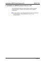
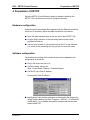
KEBA MACHINE AND
R O B O T C O N T R O L
KETOP T100
KVC - KETOP Virtual Channel
Tutorial
V 1.0
®
Notes on This Manual
At various points in this manual you will see notes and precautionary
warnings regarding possible hazards. The meaning of the symbols used is
explained below.
Failure to observe safety precautions identified by this
symbol could result in personal injury and/or damage to
machinery and equipment.
This symbol reminds you of the possible consequences
of touching electrostatically sensitive components.
Notice
Notes on use of equipment and useful practical tips are identified by the
“Notice” symbol. Notices do not contain any information that draws
attention to potentially dangerous or harmful functions.
© KEBA 2002
Specifications are subject to change due to further technical developments. Details presented may be subject to correction. All
rights reserved.
Document version: V 1.0
Filename:ketop_t100_kvc_tutorial_en.doc, last saving on: 12.3.2002, document number: KEBA AG, Postfach 111, Gewerbepark Urfahr, A-4041 Linz
Tel.: ++43 / 732 / 70 90-0, Fax: ++43 / 732 / 73 09 10, E-Mail: [email protected], www.keba.com
KEBA GmbH, Ulmer Straße 123, D-73037 Göppingen
Tel.: ++49 / 7161 / 97 41-0*, Fax: ++49 / 7161 / 97 41-40
KEBA Corp., 100 West Big Beaver Road, Troy, MI 48084
Tel. ++1 / 248 / 526 - 0561, Fax: ++1 / 248 / 526 - 0562, E-Mail: [email protected]
KETOP T100
Contents
History
Modification
from / to
V1.0
Tutorial V 1.0
© KEBA 2002
Date
15.02.02
Modified
pages
Description
Author
First Release
sam
3
General Information
4
KETOP T100
Tutorial V 1.0
© KEBA 2002
KETOP T100
Contents
Contents
1
General Information ....................................................................................................................... 7
2
Prerequisites .................................................................................................................................. 8
Required Components ............................................................................................................. 8
PC (if combined with TSC) ............................................................................................... 8
PC (standalone)................................................................................................................ 9
KEBA Components........................................................................................................... 9
Network............................................................................................................................. 9
3
Installation of KETOP Virtual Channel on PC ........................................................................... 10
4
Preparation of KETOP ................................................................................................................. 11
Hardware configuration .......................................................................................................... 11
Software configuration............................................................................................................ 11
5
Establishing the Connection ...................................................................................................... 12
6
Important Notes for Locating Errors.......................................................................................... 14
TCP/IP Connection (server side) ........................................................................................... 14
a) ipconfig ....................................................................................................................... 14
b) ping............................................................................................................................. 14
TCP/IP Connection (KETOP side) ......................................................................................... 15
Tutorial V 1.0
© KEBA 2002
5
General Information
6
KETOP T100
Tutorial V 1.0
© KEBA 2002
KVC - KETOP Virtual Channel
General Information
1 General Information
The KETOP Virtual Channel (KVC) is used as extension of a Terminal
Server Client (TSC) application (see Tutorial „KETOP T100 – TSC“).
Information that cannot be transmitted at all or cannot be transmitted in
time via the TSC (such as values from the handwheel, the override
potentiometer, membrane keys, etc.) can be transmitted to the server via
the KVC.
Since the KVC is executed entirely independently of the TSC, the TSC
functions can also be used as extension of other applications.
The application described here should only demonstrate the function of the
KVC and should not be used during real operation. For that purpose, the
functions of the KVC should be integrated in a separate C++ program (see
User's Manual „KETOP T100“ p. 57ff).
Tutorial V 1.0
© KEBA 2002
7
Prerequisites
KETOP T100
2 Prerequisites
Required Components
K1
K3
24V DC
ONLY
+24V
GND
TERMINAL IN
ES1+
ES1ES2+
n
Ru
E rro
r
ES2ED1+
ES C
ED17
8
9
4
5
6
1
2
3
.
0
-
VGA
ED2+
ED2-
RS422 OUT
KETOP
+24V
GND
ES1+
ES1ES2+
ES2ED1+
ED1-
K2
ED2+
ED2-
ETHERNET OUT
K4
1
Overview of required components
The numbering of the components in this drawing is the same in the
following tables.
PC (if combined with TSC)
Part Designation
1
NT4.0 Terminal Server Edition or
Windows 2000 Server or Advanced Server with
activated terminal services
Processor: Pentium (min. 300 MHz recommended)
Memory: 64 MB RAM (128 MB RAM recommended)
Hard disk: 1 GB free
Ethernet card
8
M-No.
-
Tutorial V 1.0
© KEBA 2002
KVC - KETOP Virtual Channel
Prerequisites
PC (standalone)
Part Designation
1
MS Windows 98/NT/2000
Prozessor: Pentium (min. 90 MHz recommended)
Memory: 64 MB RAM
Hard disk: 5 MB free
Ethernet card
M-No.
-
KEBA Components
Part Designation
K1 e.g.: KETOP T100 VGA
with Virtual Channel (already installed)
K2 Connection Cable (e.g. 50 m)
K3 Connection Box
K4 Intermediate Cable (e.g. 4 m)
M-No.
KETOP T100-008-xxx
KETOP TT 050
KETOP CB 111
KETOP IC 040
Network
Part Designation
Direct connection (cross linked cable) between
server and KETOP or via a hub
10 MBit
Tutorial V 1.0
© KEBA 2002
M-No.
-
9
Installation of KETOP Virtual Channel on PC
KETOP T100
3 Installation of KETOP Virtual Channel on PC
This tutorial assumes that the computer and the network are already
configured correctly. Therefore it only describes the KVC-specific
configurations.
► For the installation, only the downloaded files must be unpacked with
Winzip and stored in the requested path on the PC. (e.g.
c:\Programs\KVC).
10
Tutorial V 1.0
© KEBA 2002
KVC - KETOP Virtual Channel
Preparation of KETOP
4 Preparation of KETOP
Since the KETOP Virtual Channel software is already installed on the
KETOP T100, the device must only be configured correctly.
Hardware configuration
Unless the device has already been operated with the Ethernet connection,
check and, if necessary, adjust the cable connections in the device.
► Open the cable entrance area on the rear side of the KETOP T100:
► Plug the RJ45 connector of the connecting cable into the socket
provided for Ethernet.
► Connect your network or your network card of the PC to the “Ethernet
out” socket of the connecting box using a hub or a cross link cable.
Software configuration
On the Ketop, the settings for the network card must be adapted to the
configuration of the server.
► Plug in the device and turn it on.
► Call the network settings via
Start / Control Panel / Network / Onboard Ethernet.
► Set DHCP or the fixed IP address.
Example with fixed IP address:
► Modifications of the network settings must be stored in the Registry (by
calling Registry Backup via 'Start / Programs / KETOP'). To activate the
modifications, i.e. to initialize the network controller with the new data,
reboot the KETOP.
Tutorial V 1.0
© KEBA 2002
11
Establishing the Connection
KETOP T100
5 Establishing the Connection
Once the KVC server software is installed on the PC and the connection
between the KETOP and the PC is established, the connection of the KVC
clients with the server can be established.
► Start the test application "TestKVCServer.exe" in the directory KVC.
► Start the KVC server by entering "1"
The following message appears:
► Start the KVC client on the KETOP by calling the KETOP Virtual
Channel via 'Start / Programs / KETOP'.
In the first moments, the connection cannot be established because no
address has been specified for the server yet, and the message "Error:
cannot connect to server" appears.
► Click on the icon for KCV:
In the window that follows you can enter the IP address of the KVC server:
► After entering the IP address, select Connect to establish the
connection.
12
Tutorial V 1.0
© KEBA 2002
KVC - KETOP Virtual Channel
Establishing the Connection
In case of a successful connection, the colour of the icon in the Start bar
will change to green.
On the server side, the data on the display show that the connection has
been established (see following screen).
During the operation on the KETOP, all modifications are transmitted to the
server, such as actuation of handwheel, override potentiometer and
membrane keys.
By entering "?" on the server, you can call the menu with all available
commands.
By entering different letters or numbers and pressing Enter on the server,
you can check and modify the state of the KETOP on the server side.
For example:
•
Enter "i" to check the set time of the screensaver.
•
Enter "I" and then "15" to actively set the screensaver time.
•
Enter "i" to check the set time of the screensaver once again as a
confirmation.
•
Enter "g" to check the set background lighting "g"
Finish the program
To finish the program on the KETOP side, double-click on the icon in the
task bar and select Disconnect. On the server, enter "Q".
Tutorial V 1.0
© KEBA 2002
13
Important Notes for Locating Errors
KETOP T100
6 Important Notes for Locating Errors
TCP/IP Connection (server side)
To check the TCP/IP settings, open a DOS window:
► (Start -> Programs -> Accessories -> Command Prompt)
a) ipconfig
This command enables checking the IP settings of your own computer.
Depending on the configuration of your computer, the following data may
appear:
c:>ipconfig
Windows 2000 IP Configuration
Ethernet adapter Local Area Connection:
Connection-specific
IP Address. . . . .
Subnet Mask . . . .
Default Gateway . .
DNS
. .
. .
. .
Suffix
. . . .
. . . .
. . . .
.
.
.
.
:
: 192.168.181.54
: 255.255.255.0
:
b) ping
This command enables checking the connection to another computer or the
existence of another computer. Depending on the configuration of your
computer, the following data may appear:
C:>ping 192.168.181.54
Pinging 192.168.181.54 with 32 bytes of data:
Reply
Reply
Reply
Reply
from
from
from
from
192.168.181.54:
192.168.181.54:
192.168.181.54:
192.168.181.54:
bytes=32
bytes=32
bytes=32
bytes=32
time<10ms
time<10ms
time<10ms
time<10ms
TTL=128
TTL=128
TTL=128
TTL=128
Ping statistics for 192.168.181.54:
Packets: Sent = 4, Received = 4, Lost = 0 (0% loss),
Approximate round trip times in milli-seconds:
Minimum = 0ms, Maximum = 0ms, Average = 0ms
If the message "Request timed out." appears instead the selected
computer does not exist or cannot be reached.
The message "Destination host unreachable." appears if the
target address is out of the valid range of the Subnet Mask.
14
Tutorial V 1.0
© KEBA 2002
KVC - KETOP Virtual Channel
Important Notes for Locating Errors
(The target address may only differ from the own address at the positions
to which 0 is assigned in the Subnet Mask. (bitwise comparison))
TCP/IP Connection (KETOP side)
On the KETOP the program vxUtil in the Windows directory can be used to
check the network settings and the connection to the server.
Tutorial V 1.0
© KEBA 2002
•
With Info (symbol "I"), the current settings of the network adapter (under
CELAN1) can be called.
•
With Ping (symbol "2 tennis rackets"), the server (=host) can be
requested to respond. For that purpose, the IP address of the server
must be entered.
15
Important Notes for Locating Errors
16
KETOP T100
Tutorial V 1.0
© KEBA 2002