1
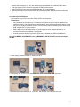
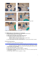
4. PMTs/counters signal cables (4) DAQ BNC connections: 50 ft. BNC cables 5a. temp sensor, GPS attenna GPS module; 5b. GPS module DAQ: Cat5 green cable 6. DAQ PC serial connection: USB 2.0 A to B cable 5) POWER-UP Sequence (after plugging in all components) 1. Set potentiometers on the PDU to minimum (fully rotate counterclockwise). 2. Plug 5V DC power supply into 110V wall outlet. 3. Check DAQ: two yellow LEDs next to USB for power 3V, 5V 4. Verify power to GPS module: red/green LED on module box Red/green together: power up condition, no fix Red/green together & sequence of green: searching and # of sats Green only: long & # of short # indicates sats 5. Check control voltage on each PDU channel: black socket ground; yellow socket positive 6) Commissioning Sequence 1. Install USB driver from "silabs" onto data computer: http://www.silabs.com/tgwWebApp/public/web_content/products/Microcontrollers/USB/en/mcu_vcp.htm 2. Open USB connection from computer to DAQ; use terminal emulator: “hyperterm” or “Zterm.” (See CRD Users Manual - Appendix C: Terminal Emulator Setup.) (default baud: 115200) 3. Verify GPS signal on DAQ; white LED (marked 1pps) should be blinking next to GPS jack (GPS IN). (may take 1 hour to lock signal) 4. Check number GPS satellites; run “DG” command. 5. Plateau and test counters. (See CRD Users Manual – Chapter 6.) 6. Configure DAQ for coincidence, gate width, and delay; run "V1" and "V2" commands. (See CRD Users Manual – Chapter 6.) 7. Take data: begin “Capture Text” with “hyperterm” or “Zterm." 7