1
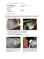
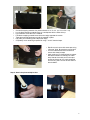
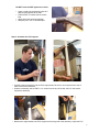
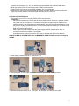
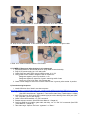
Power Distribution Unit (PDU) Power Cable for PDU Cloth Gloves Specification Sheets Safety Data Sheet (1) Box with 5VDC power input and 4 outputs including potentiometer controls for each control circuit (1) 6 ft. mono audio cable, male connectors on both ends, to get power from the connection provided on the DAQ circuit board (2) Pair clean soft cotton gloves used for handling scintillator materials to avoid dirt, scratches and fingerprints (4) Spec sheets for PMT, scintillator plastic, optical couplant, GPS antenna (1) Material Safety Data Sheet (MSDS) for optical couplant 1b) Parts List – Large Components GPS Receiver Assembly (GPS) Data Acquisition Circuit Board (DAQ) USB Interface Cable Power Supply (1) The GPS receiver and interface adapter are in a small grey plastic box to which you will attach three items: A - the 100 ft. CAT-5 coax cable which connects the GPS to the DAQ B - the temperature sensor cable with the red weatherproof coating on the sensing end C - the GPS antenna with its 9 ft. cable (1) This circuit board contains the logic, timing, multipliers, and discriminators for processing the input signals from the counters and creating the output data stream. It has interfaces to the counters, the GPS and your PC. Many of the devices on this circuit board have been preset. Do not change any settings unless specifically asked for in the instructions. The circuit board has been loaded with the current revision level of QuarkNet firmware. (1) 9 ft. USB2.0 A to B interface cable for connecting the DAQ to your PC's USB port. (1) Power supply with 5VDC 1A regulated output, female connector, to provide power to the DAQ. (Note: You must provide a PC or Mac with a terminal emulator program such as “hyperterm” or "Zterm" to display data and send keyboard commands to the DAQ.) 2) Quick Start Steps leading to a working CRD: Assemble four counters—section 3. Plug-in components—section 4. Power up – section 5. Commission CRD – section 6. Take data: Capture data to a file. (See CRD Users Manual.) Measure geometry and upload to cosmic e-Lab. (See CRD Users Manual.) 3) Counter Assembly (Read entire section before starting) General Tips • When working with electrical tape, pull tape off roll, then let it “relax” by hanging it vertically and letting it rest for 3-5 minutes. • Handle scintillator with the enclosed cotton gloves. • The PMTs are expensive electronic devices. The windows are easily damaged by excessive pressure. DO NOT force the PMT against the scintillator cookie. Assembly Steps • Wrap the scintillator. • Attach the photomultiplier tube. • Assemble the PVC support. Parts Provided Plastic scintillator with cookie Aluminum foil Photomultiplier Tube (PMT) PVC support 2