1
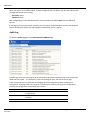
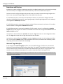
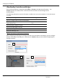
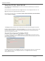
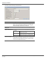
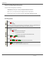
Controller to Controller Transaction Module RA56‐cATM High Performance Version 1.08 User Manual HowtoContactUs Headquarters Online Development Inc. 7209 Chapman Hwy Knoxville, TN 37920 USA In the US: 800.625.8678 International: +1.865.251.5252 Fax: +1.865.579.4740 Europe Online Development Inc. Galileo, 303‐305, 4a Planta 08028 Barcelona, Spain Phone: +34 93 394 4462 Cell: +34 678 538 671 Fax: +34 93 439 8927 AsiaPacific Online Development Inc. Shanghai, China Phone: +86 138‐1897‐4827 Email [email protected] or [email protected] Website http://www.oldi.com Go to the Support tab to submit a Service Request Knowledgebase http://kb.oldi.com Page 2 of 47 Online Development, Inc. June 2012 Contents How to Contact Us 2 Headquarters ...................................................................................................................................... 2 Europe................................................................................................................................................. 2 Asia Pacific.......................................................................................................................................... 2 Email ................................................................................................................................................... 2 Website ............................................................................................................................................... 2 Knowledgebase .................................................................................................................................. 2 Overview and Installation Instructions 5 Factory Defaults .................................................................................................................................. 5 cATM Overview ................................................................................................................................... 6 Terminology ........................................................................................................................................ 7 Using Online Help ............................................................................................................................... 7 Installing the cATM Module into a ControlLogix Chassis ................................................................... 8 Battery Information .............................................................................................................................. 8 Connecting to the cATMs Module's Web page ................................................................................... 9 DHCP ............................................................................................................................................. 9 Fixed IP Address............................................................................................................................ 9 Logging Into the cATM ...................................................................................................................... 10 Configuring the cATM’s Ethernet Ports ............................................................................................ 10 Administration 12 Device Information ............................................................................................................................ 13 System Functions ............................................................................................................................. 14 Time Sync ......................................................................................................................................... 16 User Administration ........................................................................................................................... 18 Audit Log ........................................................................................................................................... 19 Scanner Modes ................................................................................................................................. 20 Configuring the cATM Module 21 Overview ........................................................................................................................................... 21 Interfaces and Devices ..................................................................................................................... 23 Internal Tags Interface ................................................................................................................. 23 Allen-Bradley Controllers and Bridges ......................................................................................... 24 Siemens Step 7 (S7) PLCs - Models 300 & 400 ......................................................................... 26 Schneider Electric Quantum PLCs (Modbus TCP/IP) ................................................................. 26 Tags .................................................................................................................................................. 29 ControlLogix, CompactLogix and FlexLogix Tags ....................................................................... 30 PLC-5, MicroLogix and SLC Tags ............................................................................................... 31 Siemens S7 Tags......................................................................................................................... 32 Schneider Electric Quantum Tags ............................................................................................... 34 Internal Tags ................................................................................................................................ 35 Transfer Lists .................................................................................................................................... 36 Triggers ............................................................................................................................................. 38 Adding Transfers Lists to Triggers ............................................................................................... 39 Trigger Scanning.......................................................................................................................... 39 Online Development June 25, 2012 Page 3 of 47 Creating a ControlLogix Profile (optional) ......................................................................................... 40 Troubleshooting 42 Using Online Help ............................................................................................................................. 42 cATM Status Information .................................................................................................................. 43 cATM Errors and Error Codes .......................................................................................................... 43 Creating a cATM Backup in Windows 7 ........................................................................................... 43 Cannot Log in .................................................................................................................................... 44 Time Sync ......................................................................................................................................... 44 Resetting the Admin User and IP Address (Setup Mode) ................................................................ 45 Module Scrolling Display Information ............................................................................................... 46 LED Information ................................................................................................................................ 46 Specifications 47 Hardware Specifications ................................................................................................................... 47 System Requirements ....................................................................................................................... 47 Operating System ........................................................................................................................ 47 Computer Requirements .............................................................................................................. 47 Browser Requirements ................................................................................................................ 47 Page 4 of 47 Online Development, Inc. June 2012 Overview and Installation Instructions OverviewandInstallationInstructions ForInformationOnThisTopic SeePage Factory Defaults 5 cATM Overview 6 Terminology 7 Using Online Help 7 Installing the cATM Module into a ControlLogix Chassis 8 Battery Information 8 Connecting to the cATMs Module's Web page 9 Logging Into the cATM 10 Configuring the cATM’s Ethernet Ports 10 FactoryDefaults cATM modules ship with the following factory default settings: Setting Ethernet Port 1 Ethernet Port 2 User Name Password Value IP Address = 192.168.1.254 Subnet Mask = 255.255.255.0 DHCP admin admin User Names and Passwords are case sensitive. Online Development, Inc. June 2012 Page 5 of 47 Overview and Installation Instructions cATMOverview The RA56‐cATM High Performance Controller to Controller Appliance Transaction Module (cATM®) enables the exchange of data between a mix of Programmable Logic Controllers (PLCs) and Programmable Automation Controllers (PACs). The cATM module has a browser‐based configuration tool for fast and easy configuration. There is no need to program message instructions or script data transfer routines, and the cATM can function independent of other PAC/PLC logic. The cATM module installs in an Allen‐Bradley® ControlLogix® rack and can transmit data through its two Ethernet ports. The cATM can also talk directly across the backplane to and from a ControlLogix PAC installed in the same chassis, and it can bridge through various ControlLogix communication modules. Multiple cATMs can be installed in the same ControlLogix rack, and having a ControLogix PAC in the same rack is optional. Allen‐Bradley communication bridge modules that are supported include: EtherNet/IP ControlNet DH‐485 DHRIO cATM modules support data transfer between the following PLCs/PACs: SupportedControllers Allen‐Bradley ControlLogix, FlexLogix and CompactLogix PACs CommunicationMethod ControlLogix backplane (ControlLogix only) Supported bridge modules cATM Ethernet port via EtherNet/IP Supported bridge modules Allen‐Bradley PLC‐5® & SLC 500 PLCs MicroLogix PLCs, models 1100, 1400 & 1500 cATM Ethernet port via EtherNet/IP cATM Ethernet port via Industrial Ethernet Siemens S7 PLCs, models 300 and 400 cATM Ethernet port via Modbus TCP/IP Modicon Quantum PLCs Page 6 of 47 Online Development. Inc. June 2012 Overview and Installation Instructions Terminology The following terminology is used throughout this manual: Term Interfaces Devices Tags Transfer Lists Triggers Description Controllers or bridges located in slots in the local ControlLogix rack, or connected directly to one of the cATM’s Ethernet ports Internal Tags Interface (status information) Important: Configuring too many Status tags may impact performance due to the extra traffic to the controllers. Only configure the tags you need. Bridges and controllers that are remotely connected through bridges in the local rack or connected through bridges off one of the cATM’s Ethernet ports Individual data objects in the controllers that can be transferred to another controller. Tags must be created before they can be used in a Transfer List Define what data (tags) to transfer between controllers Define when to transfer data from one PLC/PAC to another. A Trigger may be linked to one or more Transfer Lists. When the Trigger conditions are true, the associated Transfer List(s) will execute the configured data transfer commands UsingOnlineHelp The cATM context‐sensitive Help can be accessed by pressing the Help icon. It is located on the bottom of the cATM interface screen, and also appears on several of the configuration screens (usually next to OK/Cancel buttons) Online Development, Inc. June 2012 Page 7 of 47 Overview and Installation Instructions InstallingthecATMModuleintoaControlLogixChassis 1. Verify that the cATM’s Setup Mode Jumper, located on the back of the module, is set to the Not Jumpered position. The following picture shows the cATM jumper configuration, with the Setup Mode Jumper set to Off (Not Jumpered). When the jumper is installed, the cATM enters Setup Mode, which temporarily sets the module's network port settings to their default values and resets the default admin password. For more information, see the Resetting the Admin User and IP Address (Setup Mode) section on page 45. 2. Install and configure your ControlLogix chassis and power supply. Refer to Rockwell Automation documentation for assistance. 3. Install the cATM module into one of the ControlLogix chassis slots. Align the module with the top and bottom guides, and then slide it into the rack until the module is firmly against the backplane connector. With a firm push, snap it into place. Like other ControlLogix modules, the cATM can be removed and inserted under power. 4. If not already on, turn the power switch (on the ControlLogix power supply) to ON. BatteryInformation The cATM uses a Lithium battery to backup the date/time settings of the real‐time clock and the BIOS settings in CMOS. The battery recharges whenever the module is plugged in and should not need to be replaced for the life of the module. The cATM must be powered for approximately twenty hours before the battery becomes fully charged. A fully charged battery will maintain your time setting for approximately 21‐days. After that, the date and time will revert to their default settings. You can tell the battery is fully charged when the Battery State LED is OFF. Note: The battery is not user-replaceable. Page 8 of 47 Online Development. Inc. June 2012 Overview and Installation Instructions ConnectingtothecATMsModule'sWebpage You need to connect a computer to the cATM module so that you can access the online configuration tool and configure the cATM’s Ethernet ports. DHCP If your network is configured to use DHCP: 1. Connect Port 2 of the cATM module to your Ethernet network. 2. Open Windows Internet Explorer and connect to the cATM’s address which will be scrolling on the front of the module. For example, http://10.0.0.xxx. Supported versions of Windows Internet Explorer are listed in the Specifications section, page 47 FixedIPAddress If your network is configured to use IP addresses in the range 192.168.1.xxx: 1. Connect Port 1 on the cATM module to your Ethernet network. 2. Open Microsoft Internet Explorer and connect to the cATM’s factory default address of http://192.168.1.254 . This address will be scrolling on the front of the module. Supported versions of Internet Explorer are listed in the Specifications section, page 47 If your network is configured to use a different IP range, follow these steps: 1. Disconnect your PC from the network. 2. Connect an Ethernet cable between the Ethernet port on your PC and Port 1 on the cATM module. 3. Access your PC’s Network Control Panel and change the TCP/IP settings for your computer’s network adapter. 4. Make a note of the current IP Address settings. You will need to restore these settings later. Online Development, Inc. June 2012 Page 9 of 47 Overview and Installation Instructions 5. Temporarily change the IP address and Subnet Mask on your PC to match the network configuration on the cATM: IP address: 192.168.1.x Subnet mask: 255.255.255.0 6. Open Microsoft Internet Explorer and connect to the cATM’s factory default address of http://192.168.1.254, which will be scrolling on the front of the module. Supported versions of Internet Explorer are listed in the Specifications section, page 47 LoggingIntothecATM You can view the status and configuration of the cATM module without logging in. However, to modify the module's configuration or perform maintenance tasks you must log in. The Login and Logout buttons are located in the status bar at the bottom of the cATM's web page. Only one user can be logged into a cATM module at a time Click the Login button at the bottom of the screen, and use the default username and password Username: admin Password: admin ConfiguringthecATM’sEthernetPorts To configure the Ethernet ports: 1. Connect to the cATM and login with an account that has Administrator privilages (for example, the default admin account). 2. Select the Administration tab and then the Network tab. 3. Configure the IP Address, Subnet Mask, and Default Gateway for each port. The IP Configuration options are: 7DHCP Static (fixed IP) Disabled Note: Each port must be on a separate subnet. Also, only one port can have Default Gateways defined. Note: If one of the ports will be connected to an EtherNet/IP, Siemens Industrial Ethernet, or Modbus TCP/IP network, be sure to configure an IP address that’s in the same subnet as the rest of the devices on that network. Page 10 of 47 Online Development. Inc. June 2012 Overview and Installation Instructions 4. Click the Save button to apply any changes. If you’ve changed the settings of the port you are connected to, the cATM will log you out and you will see the following messages: 5. If you previously changed the network settings on your PC, change the PC’s IP Address and Subnet Mask back to their original values, and then reconnect your PC to the network. 6. Connect to the cATM's web page again at its current IP address. Online Development, Inc. June 2012 Page 11 of 47 Administration Administration ForInformationOnThisTopic SeePage Device Information 13 System Functions 14 Time Sync 16 User Administration 18 Audit Log 19 Scanner Modes 20 The Administration page allows you to view and modify administration settings. The Network tab on the Administration page was explained in the previous chapter (page 10). Details concerning the rest of the tabs can be found in this chapter. The following table describes the different tabs on the Administration page: Tab Device Network System Time Sync Users Audit Log Function Modify the cATM name and add other descriptive information. Configure the network ports. Execute system functions such as backup/restore, setting log levels, clearing the event log, rebooting, and updating the cATM firmware. Configure the time on the cATM. Configure time synchronization with various controllers. Create and manage user accounts. View the audit log. The audit log consists of user‐initiated events that have occurred since the module was first started. Note: Error logs are available under the Status tab Note: You must be logged in as a user with Administrator privileges to view the Users page or modify the settings on any of the Administration pages. Page 12 of 47 Online Development. Inc. June 2012 Administration DeviceInformation To open the Device page, go to Administration Device. Change the following values and then select Save to save your changes. The information that is entered will be displayed on the Status Device tab. Field Name Description Location Contact Description Device name Description of the cATM Location of the cATM The support contact for the cATM Online Development, Inc. June 2012 Page 13 of 47 Administration SystemFunctions To open the System page, go to Administration System. Page 14 of 47 Online Development. Inc. June 2012 Administration System functions include: Function Backup Restore Set Log Level Clear Event Logs Update Description Choose what you would like to backup by checking Configuration and/or Administrative Settings. Then, click the Backup button to save a backup file on your computer. Selecting Administrative Settings backs up all module administration settings, including network settings and users. Selecting Configuration backs up only the information that pertains to the transfer of data. You can then use this backup file to configure a duplicate module in which you do not want to change any of the administration settings. If you are running Windows 7, see Creating a cATM Backup in Windows 7 in the Troubleshooting section on page 43. Press the Browse button to select a previously saved cATM backup file. Press the Restore button to restore the module to the state saved in the backup file. The cATM is rebooted after the backup is restored. You will be prompted to confirm the restore and reboot. Set the log level at which the cATM will record events. Level 1 logs errors only (default) Levels 2 through 4 log informational events in increasing detail. Use these levels for troubleshooting and support Level 0 logs only internal system errors The cATM must be restarted before a new log level will take effect. Click the Reinitialize button to restart the cATM. You will be prompted to confirm the reinitialization. Important: Keep this set at Level 1 unless directed to use another level when working with OLDI concerning a support issue. Keeping the logging set at a higher level can affect performance. If you change the logging level, be sure to change it back to Level1 when you are done troubleshooting. Clears the entire Event Log from the module. This cannot be undone. You can update cATM’s firmware from this page. Click the Browse button to select the firmware file on your computer. Firmware files have the file extension fwa. Click the Update button to perform the firmware update. Important: Do not cycle power or disconnect the Ethernet cable until the update is complete. Reboot Important: You must clear your browser's cache (In Internet Explorer, select Tools Delete Browsing History Temporary Internet Files) after rebooting the module to ensure the old pages have been cleared from your browser's memory. Click the Reboot button to reboot the cATM. You will be prompted to confirm the reboot. Online Development, Inc. June 2012 Page 15 of 47 Administration TimeSync To open the Time Sync page, click the Administration tab, and then click the Time Sync tab. The cATM module can acquire a time signal from an SNTP time server on the Internet, or from any ControlLogix or CompactLogix processor that is defined in the Configuration Editor. The cATM can also set the time on defined ControlLogix and CompactLogix PACs. Note: The cATM will only obtain and push the time while it is in Run mode. Page 16 of 47 Online Development. Inc. June 2012 Administration Section Time Zone Source Destination Frequency Save Manual Time Set Description Select the time zone for the module. The module can poll one or more sources for a time signal If you pick PLC in the Source pull‐down menu, you are provided a list of CompactLogix and ControLogix devices that were defined in the Configuration Editor If you pick Enterprise in the Source pull‐down menu, you need to specify the IP address for the Time Server in the Address field The cATM will attempt to synchronize with each of the sources in the specified order until it is successful. Timeout is the number of seconds the module will wait to receive the time signal from each source before trying the next one. Select the controller that will be synchronized to the time on the cATM. The items on this list are derived from CompactLogix and ControlLogix PACs you have defined in the Configuration Editor. Specify how often the cATM will receive and send time synchronization. A Time Sync cycle will be started when the cATM is switched to Run mode. Click the Save button to save your time settings to the cATM. To manually set the cATM’s time, select a time and date and then click the Set Manual Time button To synchronize the time and date on the cATM to the time and date on your local computer, click the Sync Current Time button Online Development, Inc. June 2012 Page 17 of 47 Administration UserAdministration To open the Users page, select Administration Users. Note: You must be logged in as a user with Administrator privileges to view this page On the Users screen you can use the New button to create new users with either Project or Administrative privileges. Administrator: Can make changes on any screen. Only Administrators can view the Users screen Project: Can make changes on the Configuration Editor screens as well as change the Mode of the cATM (i.e. Run/Idle). Cannot make changes on any Administration screens. Without logging into the cATM, you can view any of the screens. However, you can’t make any changes or change the Mode of the cATM. The following table describes functions that require security privileges: Location Status Bar Configuration Editor Administration AdministrationUsers Function Set Mode Changing anything Changing anything Viewing or changing anything on the page PrivilegeRequired Project or Administrator Project or Administrator Administrator Administrator Page 18 of 47 Online Development. Inc. June 2012 Administration When you receive a new cATM module, it comes configured with one default user who has Administrator privileges (full access to everything). Username: admin Password: admin After configuring your user and administrator accounts, delete the default admin user for additional security. If you forget your username and/or password, you can restore the default Admin account and password. See the Resetting the Admin User and IP Address (Setup Mode) section, page 45 AuditLog To open the Audit Log page, select Administration Audit Log. The audit log contains a chronological log of operational and system events that have occurred since the cATM was first started. It is displayed in reverse chronological order, with 50 events per page. Types of events that are recorded include changing the cATM's operational mode, modifying the configuration, changing of the event log level, reinitializing the module, backing up the configuration, restoring the configuration, and updating the firmware. Button Next 50 Previous 50 Export Description Displays the 50 events that occurred prior to the current 50 events being displayed Displays the 50 events that occurred after the current 50 events being displayed Exports the log to a XML file Online Development, Inc. June 2012 Page 19 of 47 Administration ScannerModes The scanner mode controls the scanning of Triggers and the transfer of data between controllers. You cannot change the mode of the scanner unless you are logged in as a user that has Project or Administrator privileges. The scanner can be in one of 3 modes: Idle, Run or Stop In Idle mode, Triggers are not scanned but the Interfaces are active. In Idle mode the scanner can be configured using the Configuration Editor. In Run mode, Triggers are scanned and the Interfaces are active. Data is actively transferred between controllers based on the Trigger logic. In Run mode the scanner cannot be configured. You can change the scanner mode to Idle or Run by using the Idle at the bottom of the page. and Run buttons on the status bar In Stop mode, Triggers are not scanned and none of the Interfaces are active. Also the Status LED on the front of the cATM module turns Red. The scanner only goes into Stop mode when a serious error has occurred. A user cannot directly put the scanner into Stop mode. If you enter Stop mode, go to Status Runtime Active Errors to view and clear any Active Errors. Once the errors are cleared you can return to Run or Idle mode. Page 20 of 47 Online Development. Inc. June 2012 Configuring the cATM Module ConfiguringthecATMModule ForInformationOnThisTopic SeePage Overview 21 Interfaces and Devices 23 Internal Tags Interface 23 Allen‐Bradley Controllers and Bridges 24 Siemens Step 7 (S7) PLCs ‐ Models 300 & 400 26 Schneider Electric Quantum PLCs (Modbus TCP/IP) 26 Tags 29 Transfer Lists 36 Triggers 38 Creating a ControlLogix Profile (optional) 40 Overview To open the Configuration Editor page, click the Configuration Editor tab. You must be logged in as a user with Administrator or Project privileges to modify settings on this page. Also, the cATM must be in Idle mode. The Configuration Editor page is divided into two panes. The left pane is a tree view of Interfaces, Transfer Lists and Triggers, and is referred to as the Configuration Editor tree. Click the [+] icon next to each object to expand or collapse the tree view The right pane is referred to as the Contents pane, and it shows the properties of objects you select in the Configuration Editor tree Online Development, Inc. June 2012 Page 21 of 47 Configuring the cATM Module The following table describes the types of objects you can configure: Object Description Interfaces Devices Tags Transfer lists Triggers Controllers or bridges located in slots in the local ControlLogix rack, or connected directly to one of the cATM’s Ethernet ports Internal Tags Interface (status information) Bridges and controllers that are remotely connected through bridges in the local rack or connected through bridges off one of the cATM’s Ethernet ports Individual data objects in the controllers that can be transferred to another controller. Tags must be created before they can be used in a Transfer List Define what data (tags) to transfer between controllers Define when to transfer data from one PLC/PAC to another. A Trigger may be linked to one or more Transfer Lists. When the trigger conditions are true, the associated Transfer List(s) will execute the configured data transfer commands To use the Configuration Editor, expand the Tree View (left pane), and then select the object to edit. Select the New button to create a new object under the selected object Select the Edit button to view or modify the selected object. Or, you can double‐click the selected object in the tree view Select the Delete button to delete the selected object. Or, select an object and then press the [DEL] key to Delete (permanently remove) it Select the Reload button to discard recent changes to the Configuration Editor. This will reload the last saved configuration. Select the Reset button to erase the entire data transfer configuration and start over. Page 22 of 47 Online Development. Inc. June 2012 Configuring the cATM Module InterfacesandDevices Interfaces are used to configure ControlLogix controllers or bridges located in slots in the same ControlLogix rack as the cATM, or to configure items connected directly to one of the cATM’s Ethernet ports. Devices are used to configure bridges and controllers that are remotely connected through bridges in the local rack or connected through bridges off one of the cATM’s Ethernet ports. If a cATM Ethernet port is connected to an EtherNet/IP network, any controllers or bridges connected directly to the EtherNet/IP network (i.e. aren’t going through a ControlLogix bridge that’s on the network) are configured as EtherNet/IP Interfaces. If a cATM Ethernet port is connected to a Siemens Industrial Ethernet network, any Siemens S7 controllers on that network are configured as Siemens S7 Interfaces. If a cATM Ethernet port is connected to a Modicon TCP/IP network, the port is configured as a Modbus TCP/IP Interface and assigned an IP address. All Modbus slave devices are configured as Devices under the Modbus TCP/IP Interface. An Interface or Device defined as a controller will contain a Tags node under it in the Configuration Editor tree. The Tags node contains all the Tags referenced for that controller. An Interface or Device defined as a bridge will contain a Devices node under it in the Configuration Editor tree. If you select the Devices node in the Configuration Editor tree, the Content Pane will display a table containing all of the Devices defined for that bridge. InternalTagsInterface If you configure the Internal Tags (#I) Interface, every user defined Trigger, Transfer List, Interface and Device will have predefined Internal Interface status tags. The statistics are available as whole structure instances which may be transferred to a suitable User‐Defined Data Type (UDT) in a single Transfer. The statistics are also available in pieces/parts for transfer to controllers that do not support UDTs. Important: Only configure the status tags you need because their use will impact performance due to the extra traffic to the controllers. Online Development, Inc. June 2012 Page 23 of 47 Configuring the cATM Module Allen‐BradleyControllersandBridges Each Interface and Device is assigned a unique Name, a Timeout, and addressing information. The Timeout specifies the timeout value in milliseconds to be used when communicating with the Interface/Device. The addressing information contains information to address the item on the network or in the rack where it is located. Interface/DeviceType Addressing Logix PAC or Bridge module accessed via the backplane Slot number EtherNet/IP Bridge or PLC/PAC connected to one of the cATM’s Ethernet ports IP Address & cATM Port Number (1 or 2) Remote EtherNet/IP Bridge or PLC/PAC IP Address Remote ControlNet Bridge or PLC/PAC ControlNet Node Number Remote DHRIO Bridge or PLC DH+ Node Number & Channel Remote DH‐485 Bridge or PLC DH‐485 Node Number & Channel AddingCompactLogixandFlexLogixControllers When configuring CompactLogix or FlexLogix controllers over ControlNet or EtherNet/IP, you first configure the PAC’s ControlNet or EtherNet port. Under the port’s Devices node, you then add the CompactLogix or FlexLogix controller. 1 2 3 Page 24 of 47 Online Development. Inc. June 2012 Configuring the cATM Module AddingDevicestoBridgemodules: If you went through the backplane to access the Bridge module (i.e. entered a slot number versus an address), then you can only add Devices that are off that Bridge’s network. You can’t go across the backplane. If you accessed the Bridge module via a network (i.e. entered the IP address or node number), then you can only add Devices that can be accessed across the backplane. Online Development, Inc. June 2012 Page 25 of 47 Configuring the cATM Module SiemensStep7(S7)PLCs‐Models300&400 Select Siemens S7 as the Interface Type for any S7 PLCs connected to a cATM Ethernet port via Siemen’s Industrial Ethernet. Each of the Siemens S7 interfaces will contain a Tags node under it in the Configuration Editor tree. The Tags node contains all the Tags referenced for that controller. Each Interface will have will have a unique Name, IP address, Remote Rack Number, Remote Slot Number, number of Retries, and Timeout. The Timeout specifies the timeout value in milliseconds to be used in communicating with the Interface. IP address, Remote Rack Number, and Remote Slot Number contain information to address the PLC on the S7 Industrial Ethernet network. There is no Port Number field because the cATM automatically knows which port to use based on the subnet. SchneiderElectricQuantumPLCs(ModbusTCP/IP) To configure a Modbus Interface, Select Modbus TCP/IP as the Interface Type. Each Interface contains a unique Name and IP address. There is no Port Number field because the cATM automatically knows which port to use based on the subnet. The Modbus Interface will contain a Devices node under it in the Configuration Editor tree. Each Device will contain a Tags node under it in the Configuration Editor tree. The Tags node contains all the Tags referenced for that controller Page 26 of 47 Online Development. Inc. June 2012 Configuring the cATM Module Each Device has the following unique parameters: Parameter Node Address Description The Modbus Node Address of the device you wish to connect to the cATM. If you are connecting via a bridge, enter the Modbus node address of the device you want to communicate with. If you are directly connecting to a Quantum PLC, set this to 0 Message Idle The idle time between messages in milliseconds. Range is 0 to 50 Register Addressing Type The type of addressing used to access Long Integers and Floating Point data, where: Normal Longs/Floats occupy two 16‐bit registers. Register order is normal. Longs/Floats occupy two 16‐bit registers. Modicon Register addressing order is WORD reversed. 32‐bit Longs/Floats occupy one 32‐bit register. Maximum Data Bytes The maximum number of register or coil data bytes contained in a single Modbus message body. Valid options are 4, 32, 64, 128, 192, and 244. If an array tag is larger than this value, multiple messages may be used to complete the data access Online Development, Inc. June 2012 Page 27 of 47 Configuring the cATM Module Parameter Description The byte gap allowed in the reading of the register or coil data block. Maximum Data Byte Gap Valid options are: 0 No gaps are allowed in the reg/coil data block. Only sequential contiguous reg/coil read requests may be combined in a request message. For example, sequential reads of Status Bits 10001 and 10003 will result in two read request messages Scattered Coil (0x0000) and Status Bit (1x0000) 1 read requests with up to a 1 byte (8 bit) gap may be combined in a single request message. For example, sequential reads of 10001 and 10003 will result in a single request message with 10002 being discarded. Scattered sequential Holding (4x0000) and Input (3x0000) register accesses must be contained or exactly adjacent Scattered sequential reg/coil read requests 8 that have up to an 8 byte gap may be combined in the same read request message Scattered sequential reg/coil read requests 16 that have up to a 16 byte gap may be combined in the same read request message Scattered sequential reg/coil read requests 32 that have up to a 32 byte gap may be combined in the same read request message Scattered sequential reg/coil read requests 64 that have up to a 64 byte gap may be combined in the same read request message Scattered sequential reg/coil read requests 128 that have up to a 128 byte gap may be combined in the same read request message Single Register Writes Determines if multiple or single register writes will occur. If this option is ON, 16‐bit register writes will be executed one at a time, 32‐bit writes will be executed one at a time, and coil writes will be executed one at a time. Array writes will require multiple messages to complete Timeout The timeout value in milliseconds to be used in communicating with the device Page 28 of 47 Online Development. Inc. June 2012 Configuring the cATM Module Tags Tags refer to individual data objects in the controllers that can be transferred to another controller. Tags can be created and deleted, but cannot be modified. In the Configuration Editor tree, each controller contains a node named Tags. When you select the Tags node under any controller, the Content pane will display all of the Tags currently defined for that controller. The read/write status of a tag is shown in the last column as a Read Only check box. If the Read Only check box is selected, you cannot use this tag as a destination in a transfer list. When the Tags node is selected, you can add or delete Tags from the controller. Select New to create a new Tag. Select Delete to delete the selected Tag. For ControlLogix PACs, the actual Tags in the controller are enumerated. From this enumeration, the user can select which tags to reference in the cATM For PLC‐5, MicroLogix and SLC 500 PLCs, tags are created to access various indexes in the controller files For Siemens S7 and Schneider Electric Quantum PLCs, the tag references must be entered by the user. Automated enumeration is not supported Online Development, Inc. June 2012 Page 29 of 47 Configuring the cATM Module ControlLogix,CompactLogixandFlexLogixTags For safety reasons, the cATM GUI does not allow you to write to digital or analog outputs in Allen‐Bradley controllers. All tags that reference digital or analog outputs are automatically assigned Read Only Privileges and they cannot be added to the Destination of a Transfer List. To add ControlLogix, CompactLogix or FlexLogix Tags to the cATM’s configuration, select the Tags node under the desired controller in the Configuration Editor tree and then press the New button on the toolbar. When the New Tag window first comes up, no Tags are displayed in the Tag tree. At the top of screen is a Tag Filter field. Enter a filter for the Tags and press the Get Tags button or the <Enter> key. All Tags that match the specified filter will be loaded into the Tag tree. Or, to get all Tags, leave the Tag Filter empty and press the Get Tags button. After the Tags that match the filter are loaded into the Tag tree, select a Tag. The Name, Data Type, and Number of Elements associated with the Tag are displayed on the right side of the New Tag Dialog. You cannot modify any of the Tag values except Number of Elements to specify how many data items at this location will be associated with the tag. When Number of Elements is greater than 1 the Tag will be handled as an array. Press the Add button to add the Tag to the cATM’s configuration. You can also double click on a Tag to directly add the Tag to the cATM’s configuration without pressing the Add button. Page 30 of 47 Online Development. Inc. June 2012 Configuring the cATM Module PLC‐5,MicroLogixandSLCTags For safety reasons, the cATM GUI does not allow you to write to digital or analog outputs in Allen‐Bradley controllers. All tags that reference digital or analog outputs are automatically assigned Read Only Privileges and they cannot be added to the Destination of a Transfer List. To add PLC‐5, MicroLogix and SLC Tags to the cATM’s configuration, select the Tags node under the desired PLC in the Configuration Editor tree, and then press the New button on the toolbar. When the New Tag window first comes up, the Location tree is loaded with Tag locations within the controller. These are file references. Select a Tag location in the Location tree. The File Reference, Data Type, Name and Number of Elements associated with the Tag are displayed on the right side of the New Tag window. You can modify the Name of the Tag to make it more meaningful. You can also modify the Number of Elements to specify how many data items at this location will be associated with the tag. When Number of Elements is greater than 1 the Tag will be handled as an array. Press the Add button to add the Tag to the cATM's configuration. You can also double click on a Tag location to directly add the Tag to the module's configuration without pressing the Add button. Online Development, Inc. June 2012 Page 31 of 47 Configuring the cATM Module SiemensS7Tags For safety reasons, the cATM GUI does not allow you to write to digital or analog outputs in Siemens controllers. All tags that reference digital or analog outputs are automatically assigned Read Only Privileges and they cannot be added to the Destination of a Transfer List. To add Siemens S7 Tags to the cATM’s configuration, select the Tags node under the desired S7 PLC in the Configuration Editor tree, and then press the New button on the toolbar. The New Tag window will contain the following parameters: Parameter Tag Name Address Type Input Output Peripheral Input Flag Bit Timers Description The desired name of the tag. It is completely at the discretion of the user. Best practice is to resemble the tag as it is labeled in the Siemens S7 controller The type of memory to be accessed ‐‐ Input, Output, Peripheral Input, Flag Bit, Timers, Counters, or Data Blocks The memory that contains the last scan of the input modules. The S7 notation (IEC) for this area is "I". This memory is read‐only for module access The memory that contains the desired output values to be written to the output modules at the end of the next scan cycle. The S7 notation (IEC) for this area is "Q". This memory is read only for module access The actual physical hardware of the input modules. The S7 notation (IEC) for this area is "PI". This area is read only for module access The memory that is intended to store interim results calculated in the program of the PLC. The S7 notation (IEC) for this area is "M". This memory is read/write for module access The memory that contains the accumulators for the timers in the S7 PLC. The S7 notation (IEC) for the timers is "T". This memory is read only for module access and the format is in BCD. The number represents the number of milliseconds that the timer has been active with a maximum value of 3999 Page 32 of 47 Online Development. Inc. June 2012 Configuring the cATM Module Parameter Counters Data Blocks DB Number Offset Description The memory that contains the accumulators for the counters in the S7. The S7 notation (IEC) for the counters is "C". This memory is read only for module access and the format is in BCD. The number represents the accumulated value of the counter since the counter has been active with a maximum value of 999 The memory that contains information for the program of the S7 PLC. They may contain the following data types: BOOL, BYTE, WORD, DWORD, INT, DINT, REAL, S5TIME, DATE, TIME, TIME_OF_DAY, CHAR, DATE_AND_TIME, STRING, or ARRAY. Descriptions of these data types should be available in the S7 PLC or Step 7 Programming Software documentation. This memory is read/write for module access The number of the desired Data Block to access. This field is only valid if the Address Type selected is Data Blocks (DB) The desired offset/number of the associated Address Type element. The following is a description of this field’s meaning for each address type: Input, Enter the slot number of the desired I/O module. Peripheral Input & Output Flag Bit Enter the byte offset within the Flag Bit memory of the desired location. Timers & Enter the number of the desired timer or counter. Counters Data Blocks Enter the number of the desired data block. Bit ID Data Type String Size The desired bit number within the data element The desired format for accessing the data. This field depends on the selected Address Type. Certain Address Types have limited access and particular Data Types will be grayed out if not applicable to the selected Address Type The size of the string to be accessed. Enter the exact size of the string as it is defined in the S7 PLC. This is only applicable to an Address Type of STRING Click Done to close the Siemens S7 New Tag window. Click the Save button to save the new tag configuration data. Online Development, Inc. June 2012 Page 33 of 47 Configuring the cATM Module SchneiderElectricQuantumTags Since most Modbus coils (0xxxxx) and output registers (4xxxxx) are internal, versus being connected to physical outputs, tags associated with Modbus coils and output registers have Read/Write Privileges and can be added to the Destination side of a Transfer List. Do NOT try to write to coils or registers connected to physical outputs. If you do, the Quantum PLC will stop communicating. All communications with the Quantum will be disabled. To recover, the Quantum PLC must be reset via power cycle. To add Quantum PLC Tags to the cATM’s configuration, select the Tags node under the desired Quantum PLC in the Configuration Editor tree, and then press the New button on the toolbar. You will first see the following warning screen. After selecting OK the New Tag window will appear. The New Tag window will contain the following parameters: Parameter Tag Name Register/Coil Offset Data Type Array Dimension Description The desired name of the tag. It is completely at the discretion of the user. Best practice is to resemble the tag as it is labeled in the Schneider Electric Quantum controller The desired area of RAM to be accessed. The four areas are: Coils (0) Input Status bits (1) Input register (3) Holding Register (4) Each area designation is followed by the most significant digit of the Quantum address, shown in parenthesis The desired offset, within the state RAM, of the data to be accessed. This, coupled with the register/coil selection, will determine the complete address of the data to be accessed. For example, selecting Holding Register with an offset of 00180 would produce a final address of 400180 The desired format for accessing the data. Register/coil types of coil and input bit can only be accessed as byte_bools. Registers may be accessed as one of the following: Int16 ‐ 16‐bit Signed Integers Int32 ‐ 32‐bit Signed Long Integers Uint16 ‐ 16‐bit Unsigned Integers Uint32 ‐ 32‐bit Unsigned Long Integers Float32 ‐ 32‐bit Floating Point The number of elements to be accessed. This allows for array transfers Page 34 of 47 Online Development. Inc. June 2012 Configuring the cATM Module InternalTags To add Internal Tags to the cATM’s configuration, select the Tags node under #I (the Internal Tags Interface) in the Configuration Editor tree, and press the New button on the toolbar. When the New Tag window first comes up, no Tags are displayed in the Tag tree. At the top of screen is a Tag Filter field. Enter a filter for the Tags and press the Get Tags button or the <Enter> key. All Tags that match the specified filter will be loaded into the Tag tree. Or, to get all Tags, leave the Tag Filter empty and press the Get Tags button. After the Tags that match the filter are loaded into the Tag tree, select a Tag. The Name, Data Type, and Number of Elements associated with the Tag are displayed on the right hand side of the New Tag window. You cannot modify any of the Tag values except Number of Elements to specify how many data items at this location will be associated with the tag. If Number of Elements is greater than 1 the Tag will be handled as an array. Press the Add button to add the Internal Tag to the cATM’s configuration. You can also double click on a Tag to directly add the Tag to the cATM’s configuration without pressing the Add button. Important: Only configure the status tags you need because their use will impact performance due to the extra traffic to the controllers. Online Development, Inc. June 2012 Page 35 of 47 Configuring the cATM Module TransferLists A Transfer List is a list of Transfers that specify what data is to be transferred between PLCs/PACs. To create a new one, highlight Transfer Lists in the Configuration Editor tree and select New. To edit or delete a Transfer List, highlight the desired list and select Edit or Delete. A Transfer List contains a unique Name for the Transfer List, a set of Transfers, and an On Transfer Error setting. The On Transfer Error setting specifies how the scanner will handle a transfer problem. On Transfer Error includes the following error options: Parameter Retry (default) Description Retry the Transfer that generated the error until it succeeds Continue Abort the Transfer that generated the error, but continue Transfer List execution Abort the Transfer List on any Transfer error Abort Note: Reference Online Help for information concerning Data / Data Type conversion during a transfer. Look under Transfer Lists in the Index or Table of Contents Page 36 of 47 Online Development. Inc. June 2012 Configuring the cATM Module A Transfer specifies a Source and a Destination and includes a Sequence Number, Wait indicator, and a Transfer on Change indicator. The Sequence Number determines the order of execution of the Transfers. Highlight a Transfer and click on Move Up or Move Down to change its order. Parameter Source Description Specifies the Tag to read the data from or a numeric or string constant. When specifying a string constant in the Source, the string constant must begin and end with a single quote and cannot contain a single quote or double quote as part of the string to be transferred. Destination Wait Specifies the Tag the data will be transferred to. If True, the Transfer List will wait for all previous transfers to complete before starting this transfer. If True, the transfer will occur whenever the source data changes. Transfer on Change If the Transfer on Change option is selected, the source data has not changed since the last Transfer List execution, and the source data is less than 10 seconds old, the Transfer destination tag will not be written. This optimization can improve performance when writing to slow networks. Online Development, Inc. June 2012 Page 37 of 47 Configuring the cATM Module Triggers Triggers define when the data is transferred from one programmable controller to another. If the Trigger Condition evaluates to TRUE (nonzero), the Trigger is fired and any associated Transfer Lists are executed. A Trigger contains the following attributes: Parameter Name Type Scan Period Condition Description The Name that uniquely identifies the Trigger Specifies how the Trigger fires. This value is fixed and cannot be modified. At this time it is always Poll The rate at which the Trigger will be evaluated The Condition under which the Trigger will fire: Description Parameter Always fires ALWAYS Never fires NEVER Fires on change of state CHANGE Fires when Compare Value 1 < Compare Value 2 LT Fires when Compare Value 1 <= Compare Value 2 LTE Fires when Compare Value 1 > Compare Value 2 GT Fires when Compare Value 1 >= Compare Value 2 GTE Fires when Compare Value 1 = Compare Value 2 EQ Fires when Compare Value 1 <> Compare Value 2 NEQ BAND (Bitwise Fires when Compare Value 1 bitwise ANDed with Compare Value 2 is non zero AND) ELT, ELTE, EGT, These conditions are the same as the conditions above, except that these conditions are edge EGTE, EEQ, ENEQ, EBAND trigger conditions. They only fire once when the condition evaluates to true. The trigger will fire again once, when the condition evaluates to false and then changes again to true Tolerance Optional comparison Tolerance value (numeric constant): Ignored for ALWAYS, NEVER, CHANGE, BAND, and EBAND conditions Used as a hysteresis value for LT, LTE, GT, GTE, ELT, ELTE, EGT, and EGTE conditions Used as a range for EQ, NEQ, EEQ, and ENEQ conditions Reference Online Help for hysteresis and range examples. Look under Triggers in the Index or Table of Contents Page 38 of 47 Online Development. Inc. June 2012 Configuring the cATM Module AddingTransfersListstoTriggers Once a Trigger is created, select the Actions node under the Trigger and then use the pull‐down menu in the Transfer List box to select the Transfer List(s) that should be executed when the trigger fires. You can add several Transfer Lists to the Actions node of a trigger. ErrorHandle If you would like a specific Transfer List to execute if an error occurs, highlight Error Handle and select New. Select a single Transfer List from the Transfer List pull‐down menu. You can only add one Transfer List to an Error Handle node. The specified Transfer List will execute when the Trigger enters and exits the Error State. Normally, the error handler moves error stats and strings into the 'master' controller. Executing the error handler on exit from the error state allows the current error strings in the master controller to be cleared. TriggerScanning Triggers are evaluated by the scanner at the rate specified by the Scan Period attribute. If the Trigger Condition evaluates to TRUE (nonzero), the Trigger is fired and any associated Transfer Lists are executed. If multiple Transfer Lists are specified, they are executed simultaneously. Once a Trigger fires, it is disabled until all of the specified Transfer Lists are completed. It is possible for multiple Triggers to simultaneously fire a single Transfer List. If an asynchronous Trigger attempts to fire a currently executing Transfer List, the Transfer List will be marked as pending and restarted as soon as it completes. The associated Trigger will be disabled until the pending Transfer List(s) start and complete. If an error occurs while reading the Trigger Compare Value 1 or Compare Value 2 tags, the error will be placed in the Active Error list, an error will be logged, and the Trigger will be disabled for a time period (usually 5 seconds, to prevent error flogging). If/when a retry of the failed Compare Value 1 / Compare Value 2 read succeeds, the active error will be cleared but the log entry will remain. Online Development, Inc. June 2012 Page 39 of 47 Configuring the cATM Module CreatingaControlLogixProfile(optional) If there is a ControlLogix PAC in the local chassis, you can configure a Generic Profile that will allow the PAC to change the cATM’s mode and gather cATM statistical information. ControlLogix Output DINT[0] is the command trigger (CmdTrigger) Increment (or change) this in the ControlLogix program to execute the command contained in DINT[1] ControlLogix Output DINT[1] is the command register (Cmd) 1=Go to Idle Mode 2=Go to Run Mode ControlLogix Input DINT[0] contains status information Bit[0] = Idle Mode indicator Bit[1] = Run Mode indicator Bit[2] = Active Error indicator The screen shot below shows the cATM in Run mode with an Active Error ControlLogix Input DINT[1] is a Free Running Counter To configure a ControlLogix profile for the cATM module: 1. Within RSLogix5000 software, right‐click on I/O Configuration and select New Module. Under +Other, select Generic 1756 Module and select OK. Page 40 of 47 Online Development. Inc. June 2012 Configuring the cATM Module 2. Setup your module as follows: Comm Format: Data – DINT Slot: cATM slot number Input Assembly Instance: 1 Input Size: 2 Output Assembly Instance: 2 Output Size: 2 Configuration Assembly Instance: 3 Configuration Size: 0 Under the Connection tab, set the Requested Packet Interval to 20 ms or greater. 50 ms is recommended. If the RPI is less than 2 ms, connection requests will be rejected. Online Development, Inc. June 2012 Page 41 of 47 Troubleshooting Troubleshooting ForInformationOnThisTopic SeePage Using Online Help 42 cATM Status Information 43 cATM Errors and Error Codes 43 Creating a cATM Backup in Windows 7 43 Cannot Log in 44 Time Sync 44 Resetting the Admin User and IP Address (Setup Mode) 45 Module Scrolling Display Information 46 LED Information 46 UsingOnlineHelp The cATM context‐sensitive Help can be accessed by pressing the Help icon. It is located on the bottom of the cATM interface screen, and also appears on several of the configuration screens (usually next to OK/Cancel buttons) Page 42 of 47 Online Development. Inc. June 2012 Troubleshooting cATMStatusInformation Under the Configuration Editor Status tab you can view the following status information: Device Status Runtime Status Event Logs Chassis Status Resource Status The cATM Online Help contains detailed descriptions of all the Status screens. Look under Status in the Index or Table of Contents. cATMErrorsandErrorCodes The cATM module includes tools for detecting and analyzing errors and events that have occurred during the transfer of data between controllers. The Active Error List displays all errors that have occurred in the module and have not yet been cleared The Event Log displays the last 2000 errors and events that have occurred in the module. The errors and events in the Event Log are displayed starting with the most recent errors/events When an error occurs in the module, the error is logged to the event log and displayed in the Active Error List. When a warning or informational event occurs in the module, the event is logged to the Event Log. Module errors and events are grouped in the following categories: Level 0 Permanent Errors Level 1 Clearable Errors Level 2 Warnings Level 3 Informational Events Level 4 Verbose Informational Events Detailed descriptions of the different Error Levels can be found in the cATM Online Help. Look under Errors in the Index or Table of Contents. A list containing different cATM Error Codes and their meanings, as well as additional information concerning how Errors are generated and handled, can be found in the Online Development Knowledgebase at http://kb.oldi.com. Under the cATM (High Performance) category search for Error Codes. CreatingacATMBackupinWindows7 On some Windows 7 systems, when you do a Backup you may not be able to choose the location or name of your backup file. It may be assigned a name automatically, and then stored in the default Favorites\Downloads directory on the local computer. If this happens, you can go to Windows Explorer to rename and relocate the backup file. Online Development, Inc. June 2012 Page 43 of 47 Troubleshooting CannotLogin You will not be able to log into the cATM if another user is logged in or you are logged in from another browser. You must wait until the other user logs out before you can log into the module. When you close the browser, the Configuration Tool will automatically log you out. However, if the browser crashes or locks up, it will be unable to automatically log you out. In this scenario, a 10‐minute timer keeps the user logged in. After the 10‐minute period elapses, the user login will be released and you can log in again. If your browser crashes or locks up, you can immediately release the local login by starting the Configuration Tool with the following URL: http://xx.xx.xx.xx/index.php?resetLocalLogin (Replace the xx.xx.xx.xx with the cATM’s local IP address or DNS name) If a user is logged into the module and leaves the Configuration Tool active, no other users will be able to log in. This can become an issue if the user leaves the workplace with the Configuration Tool open. To work around this issue, try one of the following: Reboot the module Disconnect the cables from the Ethernet port(s) and wait for 10 minutes. After 10 minutes, the logged in user will be released TimeSync If Time Syncing with the Time Source doesn’t appear to be working: Check the Time Source to make sure it’s valid Make sure the cATM time sync Frequency is set to something other than Never Save the configuration if you make any changes Page 44 of 47 Online Development. Inc. June 2012 Troubleshooting ResettingtheAdminUserandIPAddress(SetupMode) Setup Mode temporarily sets the module's network port settings to their default values. Setup Mode also allows you to reset the default admin password back to admin. The following picture shows the cATM jumper configuration, with the Setup Mode Jumper set to Off. To enter Setup Mode, you must remove the cATM from the ControlLogix rack, install the Setup Mode jumper on the back of the appliance, and then plug the module back into the ControlLogix rack. The cATM is now in Setup Mode until you remove the Setup Mode jumper or move it to the Off position. When the cATM is in Setup Mode its network port settings are temporarily set to their default values: Port 1 is set to a static IP address of 192.168.1.254 Port 2 is setup to get its IP address from a DHCP server When you start the Configuration tool while the cATM is in Setup Mode, a red displayed on the status bar at the bottom of the page. indicator is User login is disabled in this mode and all Administrator functions are available. You can reset the default admin password by pressing the Reset Admin Password button on the status bar. If you have deleted the default admin user, the admin user will be restored with Administrator privileges. You can reset the network port settings by selecting Administration Network. For additional details, refer to Configuring the cATM’s Ethernet Ports, page 10 After resetting the network port settings and/or the default admin password, close the browser, remove the cATM from the ControlLogix rack, remove the Setup Mode jumper and reinstall the cATM in the rack. Online Development, Inc. June 2012 Page 45 of 47 Troubleshooting ModuleScrollingDisplayInformation The format of the scrolling display is the following. <ModuleName>1:<Port1_IP> 2: <Port2_IP><MajorRev.MinorRev><ActiveErr> Where: <Port *_IP> is shown if the port is configured and has a valid IP address. Example (with no active errors and Port 2 disabled): Line4_cATM 1:192.168.1.254 v1.07 LEDInformation STATUS BAT Battery RED is low Off is Charged Note: When a new cATM is received the battery will be discharged. Therefore, the BAT LED will be RED. The battery is rechargeable and will recharge in the module under power. In Stop mode: Off if no active errors. Solid RED if there are active errors (high level) Either The configuration load failed or A runtime error occurred when the mode switched to stop In Idle mode: GREEN–Off– GREEN –Off, if no active errors RED –Off– RED –Off, if there are active errors In Run mode: Solid GREEN if no active errors RED – GREEN – RED – GREEN if there are active errors (low level) OK GREEN if power is applied to the unit RED if there is a major fault, typically a hardware failure Page 46 of 47 Online Development. Inc. June 2012 Specifications Specifications HardwareSpecifications Fan‐less operation Two independent 10/100M Ethernet ports ControlLogix single‐slot module Temperature: Non‐operating: 0°C to +80°C Humidity: 5 ‐ 95% non‐condensing Vibration: 2g @ 10 ‐ 500Hz Shock: Non‐operating: 50g Operating: 0°C to +60°C Operating: 30g Power Rating: 5 VDC Power Dissipation: 5 W SystemRequirements OperatingSystem Microsoft Windows 2000, Microsoft Window XP Professional with Service Pack 1 or 2 Microsoft Windows 2000 Professional with Service Pack 1, 2, or 3 Microsoft Windows Server 2003 Microsoft Windows 7 with limitations (reference page 43 of the Troubleshooting section for details) ComputerRequirements 128 Mb RAM minimum, 256 MB RAM recommended 100 Mbytes of free hard disk space BrowserRequirements Requires Windows Internet Explorer version 7 or 8 TCP/IP port 80 is used to communicate between the browser and the cATM module If using Internet Explorer version 9, select the Compatibility View icon after connecting to the cATM Online Development, Inc. June 2012 Page 47 of 47


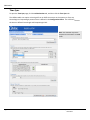

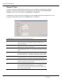
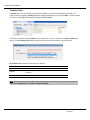
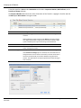

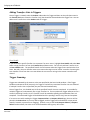
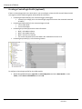
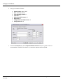


![New tool workshop: First step: After reading [TEXT] and based on](http://vs1.manualzilla.com/store/data/005783105_1-e6c0fd715dacf809f77868c696f00d08-150x150.png)