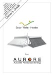
1
Maple Leaf Mews
Kingston 10
JAMAICA
Manual of Pressurized Solar Water Heater
This manual applies to Model ThermoPower-VTS30HP and ThermoPower-VTS30HP-E
“The solar energy system described by this manual, when properly installed and maintained, meets
the minimum standards established by the SRCC. This certification does not imply endorsement or
warranty of this product by SRCC.”
The supplier’s name: SunMaxx Solar
tm
.
Address: Maple Leaf Mews, Kingston 10
www.energyplusja.com
Page 1 of 48
Maple Leaf Mews
Kingston 10
JAMAICA
Contents
IMPORTANT INFORMATION AND WARNINGS .......................................................... 3
SOLAR WATER HEATER PACK AND TRANSPORT .................................................... 4
1. Features of pressurized solar water heater...................................................................... 5
2. Structure of solar water heater ..................................................................................... 6
3. Working principle ..................................................................................................... 7
3.1. Principle of vacuum tube .................................................................................. 7
3.2. Working principle of solar water heater ............................................................... 8
4. Technical data and product description ......................................................................... 9
4.1 Technical data ................................................................................................. 9
4.2 System Tolerance Information ........................................................................... 10
4.3 System start-up procedures ............................................................................... 10
4.4 System pipe anti-freezing protections .................................................................. 11
4.5 Specific notices ............................................................................................... 12
5. Installation of solar water heater ................................................................................. 14
5.1. Frame installation drawing ............................................................................... 14
5.2. Water tank and vacuum tube assembly drawing ................................................... 15
5.3. Solar water heater assembly step ....................................................................... 15
6. Pipeline installation .................................................................................................. 24
6.1 plumbing system schematic map ........................................................................ 24
6.2 plumbing connections ...................................................................................... 29
All the system labels will be packaged with the product when shipment and all of them were
made of weather proof material. Some of them must be attached to the valves with plastic or
wire tie after installation. If the label is lost or damaged for some reason, type a new one on
heavy paper stock and seal in clear plastic to make it water proof. ..................................31
6.3 Insulate the pipe .............................................................................................. 34
7. Commissioning the system ........................................................................................ 37
8. Troubleshooting ...................................................................................................... 38
9. Maintenance requirements ......................................................................................... 39
9.1. Cleaning ....................................................................................................... 39
9.2. Leaves .......................................................................................................... 39
9.3. Broken tube ................................................................................................... 39
10. Special conditional operation ................................................................................... 40
11. Other important information .................................................................................... 41
12. Warranty Card ....................................................................................................... 41
For you record: ........................................................................................................... 42
ANNEX 1.................................................................................................................. 43
ANNEX 2 Notice Label ............................................................................................... 46
www.energyplusja.com
Page 2 of 48
Maple Leaf Mews
Kingston 10
JAMAICA
IMPORTANT INFORMATION AND WARNINGS
Safety & Regulatory information
DO NOT operate this system before reading the manufacturers’ instructions.
This appliance must be installed, commissioned and serviced by an authorized person
in accordance with all applicable local rules and regulations.
This appliance is not intended for use by persons (including children) with reduced
physical, sensory or mental capabilities, or lack of experience and knowledge, unless
they have been given supervision or instruction concerning use of the appliance by a
person responsible for their safety.
For continued safety of this appliance it must be installed, operated and maintained in
accordance with the manufacturers’ instructions.
Children should be supervised to ensure they DO NOT play with the appliance.
Prevent from burn injury, touching the heat pipes in the glass tubes is strictly
prohibited. The evacuated tubes are not allowed to be exposed under the sunshine
directly before installation.
Care should be taken not to touch the pipe work as it may be HOT! Plastic pipe is
NOT suited to the water temperature and pressure that may occur in the system.
DO NOT store chemicals or flammable materials neat the appliance.
NEVER use a flammables spray such as hair spray, lacquer, paint, etc. near this unit
as this may cause a fire.
The domestic solar water heating systems will reduce your energy bill and protect our
earth by cutting the carbon footprint. SRCC published the system performance at
different location of the United Stated. You can refer to the report or certificate for the
details of the energy saving.
www.energyplusja.com
Page 3 of 48
Maple Leaf Mews
Kingston 10
JAMAICA
SOLAR WATER HEATER PACK AND TRANSPORT
All ThermoPower-VTS30HP and ThermoPower-VTS30HP-E appliances (storage
tank, evacuated tube, support base and connection accessories), are delivered well
packed to the customer.
The storage tank is placed between two round Styrofoam covers of 7 cm each, which
are tightened on the storage tank with stretch film. Then it is placed in a hard carton
pack, on which the indications of each model are displayed on the outside. The frame
and reflector are fixed beside the tank in the same box.
The evacuated tube with heat pipe and aluminum fin is packed with 4 plastic
protective elbows, attached on 4 different positions of the tube. One box can store 15
or 10 pics tube, and then packed in a wooden box.
www.energyplusja.com
Page 4 of 48
Maple Leaf Mews
Kingston 10
JAMAICA
1. Features of pressurized solar water heater
• High food grade stainless steel 304 2B. State of-the-art welding and achieves potable
water status.
• Through the 365 degree inner tube absorber, reflectors behind the tubes, the heat up
time is very fast from the time the sun rises on the east side of the tube until it goes
down on the west side – unlike flat plate, which has a high output during the sun’s
highest energy, around midday.
• Utilization all year round, even in cold, windy climates where freezing does not
occur below -2 degrees Celsius for short periods of time.
• Can operate with incoming water pressures of 0.4 MPa – no circulating pump
or controller necessary.
• The system will still function if some vacuum tubes lose their vacuum or are
accidentally damaged.
• All day tracking capabilities due to 360 degree absorber on inner tube.
• The diffuser reflector plate behind the glass tubes adds to the heat gain during blue
sunlight days.
• When consisting of more than one unit, can be installed using parallel and/or
series connections, increasing the hot water capacity supply.
www.energyplusja.com
Page 5 of 48
Maple Leaf Mews
Kingston 10
JAMAICA
2. Structure of solar water heater
Component description:
HEAT PIPES: An evacuated-tube collector contains several individual glass tubes,
each containing an aluminum fin and a heat pipe. The heat pipe transfers the heat
efficiently to the water in the tank.
WATER TANK: The storage tank is made of three layers: inner shell, intermediate
foam insulation and outer cladding. The shell is built to hold water pressure maximum
of 150psi. Shell material is corrosion-proof food-grade stainless steel. Foam insulation
thickness is decided to maintain the tank water temperature self-sustainable during
continuous unclear days in the coldest wintertime. Outer cladding is normally
galvanized sheet metal, providing a fine surface finish and a long-lasting life.
EVACUATED TUBES: Top quality double-walled tubes are chosen. There is an
aluminum or copper coated mirror on the inside surface of the inner glass wall. The
mirror well traps the thermal energy inside the tube. On the metal mirror layer, there is
selective absorption coating, which converts over 99% energy of visible and invisible
lights.
www.energyplusja.com
Page 6 of 48
Maple Leaf Mews
Kingston 10
JAMAICA
The outer glass wall acts as glazing, creating a vacuum space and protects the coating
against weather. On the inner surface of tube ends, a silver-colored getter material is
applied, which absorbs the remaining gases inside the tube hollow space. Deducting
the absorption and surface reflection of the outer wall of a tube, the overall efficiency
of a tube is over 92%.
REFLECTOR: Reflector is silver coated reflecting panel. The reflectors can improve
solar system thermal efficiency and reinforce the frame structure.
FRAMES: Frame is made of rustproof material. A frame may have full-length rear
legs, suitable for flat surface installation, or, shortened rear legs, suitable for sloped
surface installation. Length of rear legs could be cut to fit at site.
3. Working principle
3.1. Principle of vacuum tube
The vacuum tube is composed of inner tube, outer tube, selective absorption layer,
vacuum space, inspiratory layer. The outer wall of the inner tube is the selective
absorption layer. The space between outer tube and inner tube is the vacuum space.
At the bottom of the outer tube, there is an inspiratory layer which can be used to
absorb the remnant air.
www.energyplusja.com
Page 7 of 48
Maple Leaf Mews
Kingston 10
JAMAICA
3.2. Working principle of solar water heater
The vacuum tubes absorb the solar energy, and aluminum fin pass the heat energy
to the heat pipe. The liquid medium in the heat pipe is heated by the heat energy, and
then turns into the gas medium. The gas medium flows up to the top of the heat pipe
and transfer the energy to the cold water in the tank, at the same time the gas medium
turns into the liquid one and flows down. The liquid medium keeps recycling and the
water in the tank will become hot.
www.energyplusja.com
Page 8 of 48
Maple Leaf Mews
Kingston 10
JAMAICA
Fig 3.1 Solar water heater working sketch map
4. Technical data and product description
4.1 Technical data
Model
Number of Tubes
Gross area
Tank Volumetric Capacity
Weight Empty
Fill weight
Length of Tubes
Outer tube diameter
Tube thickness
Tube Thermal Expansion
Absorptive coating
Absorbency
Emittance
ThermoPower-VTS30HP
30
2
4.45m
300L
90Kg
330Kg
1800mm
Ø58mm
1.6mm
-6
3.3×10 m/m°C
Graded Al-N/Al
>92%(AM1.5)
7%(100℃)
www.energyplusja.com
Page 9 of 48
Maple Leaf Mews
Kingston 10
JAMAICA
Vacuum
Heat Loss
Insulation
Stagnation Temperature
Maximum working temperature
Maximum Working Pressure of all
circuits
Working pressure
Maximum wind and snow load
Tilt Angle
Inlet and Outlet
T&P Valve Port
Frame
P<0.005Pa
<0.8W/㎡
Polyurethane,55mm
<220℃
90℃
0.6MPa
0.4MPa
0.49kN/m²
45°
1/2inches
1/2 inches
Aluminum Alloy
4.2 System Tolerance Information
Freeze tolerance limits are based upon an assumed set of environmental conditions.
Extended periods of cold weather, including ambient air temperatures above the
specified limit, may cause freezing in exposed parts of the system. It is the owner’s
responsibility to protect the system in accordance with the Supplier’s instructions if
the air temperature is anticipated to approach the specified freeze tolerance limit.
4.3 System start-up procedures
After the system installation, check there is no leakage in the system and follows the
following steps to start up the system.
Step 1: Connect Garden Pipe to Drain Valve V4, and keep V4 Open.
Step 2: Open the following valves: V0, V2, V4 and shut off the following valves: V1,
V3, and V5
Step 3: Keep the water running for 5 minutes to flash out the solder or stains after the
water from V4 is observed.
Step 4: Shut off V4 and Open V3, and the system is in normal operating status.
www.energyplusja.com
Page 10 of 48
Maple Leaf Mews
Kingston 10
JAMAICA
4.4 System pipe anti-freezing protections
This is a direct DHW system. The plumbing copper pipe needs anti-freezing
protection when the lowest temperature is below 23 Fahrenheit or -5 Celsius in the
coldest climate. The detail anti-freezing protection is described as follows.
The tables SRCC uses to evaluate the freeze protection provided by pipe insulation
indicate that 1.5 inches of insulation on a 0.75 inch type L copper pipe will protect the
pipe down to about 14F. It would be ok for the whole system if the entire pipe was
insulated well under this temperature condition.
It would be better to drain down the whole system if the temperature is lower than
o
14 F to avoid the connecting pipe freezing. The connecting pipe can be protected
against freeze damage.
In case of black out or power outage occurs during the cold weather when the
temperature is lower than 14 Fahrenheit or -10 Celsius, a system drain out procedure
must be followed as follows, and the existing Aux water heater must have adequate
capacity, listed and labeled by an accredited listing organization to continue provide
adequate hot water.
Step 1: Shut off V2 and V3 Solar Isolation valves to Isolate Solar System.
Step 2: Open V1 to using Aux hot water heater system, and bypass the solar water
system. Ensure the V0 is open.
Step 3: Connect Garden Pipe to both Drain Valve V4 and V5.
Step 4: Put the both Garden Pipes in the house drain dock or sinks.
Step 5: Open both V4 and V5 drain valves, until no more water comes out of either
pipes.
Step 6: Shut off both V4 and V5 drain valves.
When the electricity power is back to normal, follow the system start-up procedures
to set up the system to normal operation.
www.energyplusja.com
Page 11 of 48
Maple Leaf Mews
Kingston 10
JAMAICA
4.5 Specific notices
4.5.1 Aux Hot Water Heater
The system is not a replacement of the existing Aux Hot Water Heater. It is installed at
the upstream of the existing conventional hot water heater. The Aux Hot Water Heater
must be maintained as usual. The Aux water heater must have adequate capacity, listed
and labeled by an accredited listing organization. The Aux water heater should have the
proper built in insulation by the accredited organization. If the Aux Water
Heater doesn’t come with the insulation, it should be covered with a minimum R2.2
insulation with thickness of 1/4”. (GUIDE: 6.1.1.4)
4.5.1 Different metallic materials
To prevent galvanic corrosion, a dielectric union or coupling is recommended to
install in between the copper pipe and steel tank. (GUIDE: 6.1.1.10)
4.5.2 System Tank (GUIDE: 6.1.3.2)
The direct system comes with 63 gallons tank and no heat exchanger, hence no extra
tank is needed.
4.5.3 Heat Transfer Fluid (HTF) inside the heat pipe (GUIDE: 6.1.3.6 and 6.3.7)
The HTF inside the heat pipe is a small amount of pure water at a very low pressure.
The heat pipe, HTF are built as one unit, no refill is needed, and the water inside will
not be reduced.
No other fluid shall be used that would change the original classification of this
system. Unauthorized alterations to this system could result in a hazardous health
condition.
4.5.4 Temperature Sensor Wiring and System Monitoring (GUIDE: 6.1.5.5 and 6.4.1)
Connect each of the temperature sensors with the cold water pipe and hot water pipe
respectively. Put one-foot R4.4 insulation on both sensors. The sensor and pipe
intersection point should be in the middle of the one foot insulation.
To determine whether the solar system is working, observe the thermometer when the hot
water is being used in the house. The water returning from the collector on a sunny day
should be at least 10 Fahrenheit warmer than the water going up to the collector. The
temperature of the cold water and hot water is displayed on the monitor.
4.5.5 The insulation of the final 5 feet to the auxiliary water heater (GUIDE: 6.1.6.3)
The insulation of the final 5 feet to the auxiliary water heater shall be insulated with
2
R-0.46 K m /W or greater insulation.
www.energyplusja.com
Page 12 of 48
Maple Leaf Mews
Kingston 10
JAMAICA
4.5.6 Public Traffic Statement (GUIDE: 6.3.17)
Components exposed to public traffic should be maintained below 140°F or
insulated/isolated to prevent any hazards to the public traffic.
4.5.7 Components accessibility (GUIDE: 6.4.6)
All components should be accessible for maintenance and servicing.
4.5.8 Installation and Maintenance Practices (GUIDE: 6.5.5 and 6.5.10)
Do not impair enclosure function. Do not allow vermin intrusion. Ensure to meet
applicable codes and national Roofing Contractors Assoc. practices. The entire
system should be checked by the installer once every two years.
Follow the specific codes and practices to penetrate the structural members for the
solar system.
4.5.9 Safe practices (GUIDE: 6.5.11)
Building materials adjacent to solar components are not exposed to elevated
temperatures.
4.5.10 System mounting (GUIDE: 6.5.12, 6.5.13, 6.5.14 and 6.5.19)
Allocate a place is not shaded during 10:00AM to 3:00PM, and keep the solar panel
facing south with 45 degrees of adjustment tolerance. The pitched degree of the panel
should be close to the latitude of the location.
All the piping should proper support according to the plumbing codes. These supports
must not compress the insulation.
Any structural member or fire rated assembly should not be reduced after penetration
during the installation. It will be up to the local code to dictate exactly how this is
done. The outdoor pipes should be insulated with R6.6 insulation with thickness at or
greater than 1 inch. The indoor pipes should be insulated with R2.6 with thickness at
least 1/4”.
4.5.11 Projected components need to be replaced
The glass vacuum tubes might need to be replaced after it is broken by the unexpected
hazards, such as hit by the hard material. Please contact to the installer to order the
parts and do the replacement. The battery of the temperature monitor needs to be
replaced when the battery is out. The battery can be purchased at store.
www.energyplusja.com
Page 13 of 48
Maple Leaf Mews
Kingston 10
JAMAICA
5. Installation of solar water heater
5.1. Frame installation drawing
www.energyplusja.com
Page 14 of 48
Maple Leaf Mews
Kingston 10
JAMAICA
5.2. Water tank and vacuum tube assembly drawing
5.3. Solar water heater assembly step
5.3.1 Installation of frame:
Firstly, open the packing case to check the fittings related with the frames and
their quantity. They include front and rear legs, assistant bars, cross bars, tank
brackets, tail stock track, tail stocks, reflectors, cousins as well as screw bag.
Fig 1
Fig 2
www.energyplusja.com
Page 15 of 48
Maple Leaf Mews
Kingston 10
JAMAICA
Step 1. Take the tail stock track out and
Step 2. Take the reflectors out and connect
put it under the frame. Open the screw
them with front legs by bolts and nuts.
bag, finding the bolts that match the
Attention: the reflector near to the tail
connecting holes to connect the tail
stock track should not be installed now so
stock track with front legs.
as to operate more easily in the installation
of the rear legs and assistant bars.
Fig 3
Fig 4
Step 3. Find the tank brackets and
Step 4. Take the rear side legs out and
connect them with rear legs. Attention:
connect them with the corresponding
The installation of the three tank
connecting holes of the tank brackets by
brackets is the key point; observe
bolts. Observe carefully how the rear side
carefully so as to avoid the faulted
legs are collected with the tank brackets.
installation.
Fig 5
Fig 6
Step 5. Connect the front legs with rear
Step 6. Take the cross bars out that are
legs by assistant bars, pay attention to
used to fasten the rear legs, group them
the length order of assistant bars. Take
together first. Connect the cross bars
www.energyplusja.com
Page 16 of 48
Maple Leaf Mews
Kingston 10
JAMAICA
the rear middle leg out and connect it
with the two adjacent rear legs.
with the tank brackets. Attention: Put
The cross bars can fasten the rear legs
two angle irons together as the rear
well for fear that the strong wind
middle frame and then connect them
destroys the frames.
with the tank brackets. The assistant
bars are collected with the reflectors by
the same screw. Take the last rear leg out
and connect it with the tank brackets.
Then use the assistant bars to connect
the rear and front legs in the same way
mentioned above.
Fig 7
Fig 8
Step 7. At last connect the cousins to the
Step 8. Turn the frame over and put it on
corresponding front and rear legs.
the ground at the installation angle
between the front legs and rear legs.
www.energyplusja.com
Page 17 of 48
Maple Leaf Mews
Kingston 10
JAMAICA
5.3.2 Installation of the tank:
Fig 1
Fig 2
Step 1. Screw off the nuts
Step 2.
from the
accessories
connection bolts
Fig 3
Install the Step 3. Install the T.P
and revolve valve.
of the water tank. Take the
the small red cap of the
water tank out. Put it on
air vent on the top to
the well-installed frames
ventilate.
slowly and lightly.
.
Attention that insert the
bolts of the water tank
into the
corresponding
connecting holes of the
tank brackets.
5.3.3 Installation of the heat pipe and vacuum tubes
Step 1. Firstly sheathe the anti-dust circles onto the vacuum tube.
Step 2. Take the adjustable tail stocks down.
Step 3. Pull the heat pipe out of the vacuum tube about 20 centimeters.
Step 4. Sheathe the white Teflon gasket into the heat pipe and put it onto the convex
of the copper circle.
www.energyplusja.com
Page 18 of 48
Maple Leaf Mews
Kingston 10
JAMAICA
Step 5. Put the heat pipes into the water tank slowly. Attention: If it is not easy and
convenient to do, we can adjust the angle between the water tank and the ground
properly.
Step 6. Connect the joint screw with the nuts inside the water tank and screw them
tightly by 22mm spanner. Please pay attention to the tightness extent, avoiding being
too loose to cause water leakage.
Step 7. Install all the heat pipes according to this method. Adjust the angle and the
inappropriate places, keeping them horizontally. Then charge water into the tank to
check if there is a leakage from the connections.
Step 8. Insert the vacuum tube into the anti-dust circle of water tank, and then install
the tail stocks that have been taken down. Attention: when inserting the vacuum
tubes, they cannot be revolved for fear that they destroy the heat pipes.
www.energyplusja.com
Page 19 of 48
Maple Leaf Mews
Kingston 10
JAMAICA
At last fasten all the screws.
5.3.4 Solar water heater installation and attention
This STEP requires you to locate your hot water heater. The collector should face
approximately South (plus or minus 20°). Use a declination value from a map or
declination table to determine the direction of true South from the compass reading.
The collector should be tilted at the latitude angle plus 15° for best winter operation
o
and latitude minus 15 for best summer performance. Tilt at latitude for best year
round performance.
A good GPS will also provide accurate compass headings and your exact latitude. If
you do not have a compass or GPS, wait until solar noon and the shadow of a vertical
stick or surface will point due North. True South is 180° from true North. HINT:
MANY SOLAR SYSTEMS ARE PLACED AT THE ROOF SLOPE WHICH IS
LESS THAN LATITUDE MINUS 15°, BUT IS MORE AESTHETICALLY
PLEASING,
WITH
ONLY
A
SMALL
10%
PENALTY
IN
ANNUAL
PERFORMANCE.
The latitude of your location can be found on the Internet or in your local paper. The
latitudes of some selected U.S. cities are presented in Table 5-1 for reference. (HINT:
Look at other solar collectors in your area, see how they are oriented to South and
elevated for latitude) .The report includes a solar sitting template to show the effects
of shadowing from trees or nearby buildings, declination map and other useful
information about system sitting.
www.energyplusja.com
Page 20 of 48
Maple Leaf Mews
Kingston 10
JAMAICA
Table 5-1 Approximate Latitudes of Selected U.S. Cities
City (arranged by increasing latitude)
Latitude (all North)
Anchorage, AK
62°
Juneau, AK
58°
Seattle, WA
47.5°
Portland, OR; Minneapolis, MN; Bangor
ME
Buffalo, NY
45°
Chicago, IL; Boston, MA; Detroit, MI
42°
Denver, CO; Indianapolis, IN; Philadelphia,
PA
Kansas City, MO; St. Louis, MO;
Washington, DC; Cincinnati, OH
Reno, NV
40°
39.5°
San Francisco, CA; Sacramento, CA
38°
Nashville, TN
36°
Albuquerque, NM; Memphis, TN
35°
Los Angeles, CA
34°
Phoenix, AZ; Charleston, SC
33°
San Diego, CA; Savannah, GA
32°
Houston, TX; New Orleans, LA;
Jacksonville, FL
30°
Tampa, FL
28°
Brownsville, TX; Miami, FL
26°
Honolulu, HI
21°
Hilo, HI
20°
www.energyplusja.com
Page 21 of 48
43°
39°
Maple Leaf Mews
Kingston 10
JAMAICA
Three reference poses are given below. However, in deciding the specific location and
pose of a unit, the installer should consider:
1) Choose the strong foundation and safe place
2) Take a location with optimized sunshine exposure
3) Minimize plumbing length for decreasing heat loss
4) Ensure the aesthetic view with the surrounding environment
5) Perform safe operations to prevent from injury during installation.
o The solar water heater must be installed in locations with wind and snow load
lower than 0.49kN/m². If the wind and snow load in the locations more than this
value, please strengthen the installation of system.
o The best time to install the heat pipes and vacuum tubes is in the morning or in the
evening or the time when the sunlight is weak. If there are strong sun lights, the
heat pipes will be heated quickly and the temperature will reach above 100
degrees. That will scald the installation workers easily. Or wrap the vacuum tubes
by a piece of cloth so that they are not exposed under the sun lights directly.
www.energyplusja.com
Page 22 of 48
Maple Leaf Mews
Kingston 10
JAMAICA
o After installing and adjusting solar water heater, connect cousins with building
plate by the inflated bolt. Fix it more than 4 steel ropes to avoid the demolishment
from the strong wind.
o
Be sure that no leakage in pipeline, joints, valves and etc.
o The pipeline outside must be dealt with heat preservation and anti-freezing. In
some special cold area, the emptier or restrained temperature anti-freezing cable
should be added.
o If the solar water heater is not in the protecting scope or lightning conductor fixed
in the buildings, the user should add the lightning conductor. The local power
department must connect the roof conductive part to the ground wire with at least
16 mm grounding cables. For building height (installation height) less than 20
meters, do not need to adopt the special measures to protect lightning strikes
o When penetrations are required in structural members to accompany passage of
solar components, those modified structural members shall comply with local
building codes.
o Building materials adjacent to solar equipment shall not be exposed to elevated
temperatures which could accelerate their deterioration. Many non-metal roofing
materials will soften in the temperature range of ---and begin to degrade above
this temperature.
o
The design and installation of systems shall not impair emergency movement of
the building occupants.
The installation shall:
o NOT IMPAIR ENCLOSURE FUNCTION
o NOT ALLOW VERMIN INTRUSION
o
MEET APPLICABLE CODES AND NATIONAL ROOFING CONTRACTORS ASSOC.
PRACTICES.
www.energyplusja.com
Page 23 of 48
Maple Leaf Mews
Kingston 10
JAMAICA
6. Pipeline installation
6.1 plumbing system schematic map
ThermoPower-VTS30HP is a solar thermal hot water heater system which pre-heats
city water with solar energy prior to feeding to the conventional hot water heater. It
can be integrated with the existing gas, electricity, propane or oil hot water heater by
installing at the upstream of the existing hot water heater. Food grade materials should
be used for all water contact areas.
A mixing valve must be installed if the homeowner does not have one currently. Set
o
o
the output water temperature at a point of 48.9 C (120 F).
o
The tank upper temperature limit is 300 F and 130 psig. As the thermosiphon
system has no way to stop the operation of the solar collector, always install a TP-R
valve to release some high temperature water out of the tank then mains water will
charge the tank to keep the tank within normal conditions.
The T&P valve releases some water out of the tank when the temperature is more
than 194°F, or the water pressure is above 58 PSI to ensure the safety of the system.
And the specification of the TP-R is:
·
Inlet:1/2 in tapered male thread
·
Outlet:1/2 in parallel female thread
·
Maximum opening temperature:90℃/99℃
·
Rated working pressure: 0.4MPa/0.6MPa
·
Maximum working pressure:1.5MPa
If you have a long time to go out of your home, and the system will not be used
during that period, we recommend you drain down the system and close the inlet
valve to avoid overheating. And in order to prolong the system use life, you had
better to cover the collector using a canvas clothes a mat.
www.energyplusja.com
Page 24 of 48
Maple Leaf Mews
Kingston 10
JAMAICA
When the tank gets too hot as some irrationality actions, please drain down some hot
water and then charge the mains water to cool down the system slowly.
All exposed areas need to be well insulated to resist freezing. The well insulated tank
keeps the hot water in the tank from losing too much energy through the night. The
system can absorb energy at most of the weather conditions even at full cloudy day in
the cold winter. The collector tubes can still get energy from infrared passing through
the clouds at full cloudy day.
All labeled valves (V1 to V5) must be installed at an adult’s reachable place. Draining
valves (V4 & V5) must come with hose bibs that can connect a garden hose for
draining purpose.
Piping should be sloped toward drain ports with a drainage slope of no less than 2 cm
vertical drop for each meter of horizontal length (1/4 inch per foot).
The illustration is the installation pipe line of pressurized solar water heater. The
directions of each valve and the corresponding positions should be correct. There
should be no leakage in the tie in. The pipe line must be dealt with heat preservation
and anti-freezing.
Underground piping subject to vehicular traffic shall be installed to withstand the
additional loading applied by this traffic. The trenches and backfill shall be free of
sharp objects in contact with the pipe.
As the system is a solar only system, there will be some days that it cannot meet the
user heat demand if the solar irradiance is not ideally. It requires an aux water heating
equipment to ensure that all the days can meet the user demand.
Our system can plumb with electrical, gas or oil water heater, the detail connecting
please reference the below diagram. Please note that, when you choose the backup
water heater,
“THE AUX WATER HEATER MUST HAVE ADEQUATE CAPACITY,
LISTED AND LABELED BY AN ACCREDITED LISTING ORGANIZATION.”
www.energyplusja.com
Page 25 of 48
Maple Leaf Mews
Kingston 10
JAMAICA
The backup water heater thermostat set point can be 51.7°C (125°F) to meet the
final delivery water temperature.
Regarding the electrical back up water heater, you can choose to connect both of
the heat elements to speed up heat rate, or you can only connect one on the top of this
water heater. It would be better to get some suggestions from the field-wiring installer
to ensure all the wire can meet the heat element maximum power.
The above is a reference plumbing connection diagram. The formal plumbing architecture
design and blueprint drawing shall always be done by a licensed architect and signed by licensed
plumbers. Acquire the proper working permits from the local city building department before the
installation. Install the system by a licensed contract with solar install certificate. Request and
perform the inspection and sigh-off after installation.
Important Notice and Warnings
Prevent from burn injury, toughing the heat pipe in the glass tubes is strictly prohibited. The
evacuated tubes are not allowed to expose under the sunshine directly before the installation.
www.energyplusja.com
Page 26 of 48
Maple Leaf Mews
Kingston 10
JAMAICA
The inlet and outlet port size is 1/2” tube, you can choose the pipe size between the
water supply and water tank connections can be 1/2” or 3/4”. And the safety valve
size is also 1/2”. Make sure all the safety valves are in normal condition before
flushing the system.
The temperature monitor and sensor shall be installed suitably to ensure the system
can work normally. There are two recommended methods to install temperature
sensor into the inlet and outlet pipe.
Method 1, use a three way valve and sensor pocket to install the temperature sensor at
the inlet and outlet port of the water tank.
Fig1. sensor pocket
Fig2. the top end of the
Fig3.
sensor pocket
connect
sensor
pocket
with three way
valve
It would be better to install the sensor at the inlet and outlet port of the tank to
measure the temperature accurately.
Method 2, if the sensor pocket is not available when install the system, you can
choose an easier method to install the temperature sensor.
step1. Put the
temperature Fig2. Use duct tape to fix
sensor close to the inlet and
outlet copper
the sensor.
pipe. Keep
Fig3. Then insulate
the
whole
PU
foam.
them contact tightly.
www.energyplusja.com
Page 27 of 48
pipe
with
Maple Leaf Mews
Kingston 10
JAMAICA
The sensor shall be install as close as possible to the inlet and outlet port of the tank
and insulate well.
After install temperature sensor, the sensor wiring shall go through the pipe to get into
the house,and then connect with temperature monitor. The monitor shall be installed
in a place where can be monitored expediently and keep it dry.
The recommended temperature monitor SmartMaxx-DHWV2 can be installed
expediently, and you just need fix the monitor onto the wall and insert the thermal
sensor connector into the sensor jack of the monitor. You can refer the monitor
diagram below.
To determine whether the solar system is working, observe the thermometer when the hot
water is being used in the house. The water returning from the collector on a sunny day
should be at least 10 Fahrenheit warmer than the water going up to the collector. The
temperature of the cold water and hot water is displayed on the monitor.
The monitor main unit shall work normally under the ambient temperature between 10 and 60°C, the humidity under <90%RH. The thermal sensor shall meet the
working temperature between -40-110°C. The recommended measure accuracy is
0.1°C.
If the solar water heater is installed either on a metal roof or in a trafficable area, such
as on an accessible roof, then the solar hot and solar cold pipes must be insulated. The
solar hot and solar cold pipes may be required to be insulated to comply with local
regulations.
www.energyplusja.com
Page 28 of 48
Maple Leaf Mews
Kingston 10
JAMAICA
6.2 plumbing connections
Components list and Valve labels
ID
Name
Normal
Model/technical
operation
specification
Photo
Quantity
position
V0 City
shut
water ON
3/4” ball valve
off
valve
www.energyplusja.com
Page 29 of 48
1
Maple Leaf Mews
Kingston 10
JAMAICA
V1 Solar
OFF
3/4” ball valve
1
ON
3/4” ball valve
1
ON
3/4” ball valve
1
Bypass
valve
V2 Solar
isolation
valve
V3 Solar
isolation
valve
V4 Solar Drain OFF
valve
3/4”Drains hose
outlet
connection with
NPT
1
threaded inlets
V5 Solar Drain OFF
valve
3/4”Drains hose
outlet
connection with
NPT
1
threaded inlets
V6 Mixing
valve
Set temperature 1/2" WATTS series 70A
Tempering
Valve
48.9oC
(120°F-160°F)
1
temperature range: 120+F
to 160+F.
Maximum Pressure: 150psi
(10 bar).
Size Range: 1/2 to 3/4 in.
(15 to 20mm)
V7 TPR valve
Normal
WYA-15 1/2’’
operation
Meet ANSI Z21.22
condition
Inlet:1/2 in tapered male
thread
Outlet:1/2 in parallel fe
male thread
www.energyplusja.com
Page 30 of 48
1
Maple Leaf Mews
Kingston 10
JAMAICA
Maximum opening temp
erature:90℃/99℃
Rated working pressure:
0.4MPa/0.6MPa
Maximum working pres
sure:1.5MPa
V8 Air
vent OPEN
R99Y
1
valve
V9 No-return
OPEN
valve/check
Maximum
operating
1
pressure 400psi
valve
Connections list
ID
Name
Connection Fluid
1
requirements
Cooper
Materials shall meet the
3/4’’
loop
standards of the national
Tube
sanitation foundation
Connection 3/4”
2
Material Model photo
Cooper
3/4’’
CxCxC
Tee and
Materials shall meet the
standards of the national
sanitation foundation
Couplings
www.energyplusja.com
Page 31 of 48
Maple Leaf Mews
Kingston 10
JAMAICA
Connection 3/4”
3
Cooper
3/4’’
Materials shall meet the
Copper x
standards of the national
Female
sanitation foundation
Adapter
Connection 3/4” x
4
Cooper
1/2”
Copper x
3/4” x
Materials shall meet the
1/2”
standards of the national
sanitation foundation
male
Adapter
ID Front label
Back Label
V0
City water shut off valve. Shut this
valve will shut the water supply for the
solar and Hot Water System.
City water shut off valve
OPEN
Normal operation position: OPEN
V0
V1
Solar Bypass Valve
Solar Bypass Valve
CLOSE
Normal Operation Position:
CLOSE
V1
www.energyplusja.com
Page 32 of 48
Maple Leaf Mews
Kingston 10
JAMAICA
V2
Heat transfer fluid identity and AWWA class
1 warning that fluid may be discharged at
Solar Isolation Valve
OPEN
high temperature and/or pressure.
Unauthorized alterations to this system could
V2
result in a hazardous health condition
V3
Heat transfer fluid identity and AWWA class
1 warning that fluid may be discharged at
Solar Isolation Valve
OPEN
high temperature and/or pressure.
Unauthorized alterations to this system could
V3
result in a hazardous health condition
V4
Solar drain valve is used to drain the
solar system.
Solar Isolation Valve
OPEN
Normal operation position: CLOSE
V4
V5
Solar drain valve is used to drain the
solar system.
Solar Isolation Valve
OPEN
Normal operation position: CLOSE
V5
All the system labels will be packaged with the product when shipment and all of
them were made of weather proof material. Some of them must be attached to the
valves with plastic or wire tie after installation. If the label is lost or damaged for
any reason, type a new one on heavy paper stock and seal in clear plastic to make it
water proof.
www.energyplusja.com
Page 33 of 48
Maple Leaf Mews
Kingston 10
JAMAICA
§
§
§
§
The freeze protection label must be attached to the water tank drain valve.
Hot warning label must be attached to the position where the mix-valve is installed.
The system label will be attached on the front side of the tank.
And the valve V0-V5 label must be attached or hang on the valve which installed
according to the diagram in this manual.
6.3 Insulate the pipe
For the installation of the pipeline system and power cord (including indoor and
outdoor parts) of the flat solar system, the pipeline shall go through the airway of the
house, and should not be installed in the flue; the indoor part shall be open line and
shall not bury the pipeline of the solar system and power cord in the cement without
any protection, as the connections of pipeline and the power cord may need
maintenance or repair. Upon installation, the user shall guarantee that the connections
of pipelines and the power cord are easy to maintain or repair. If the user installs the
pipeline of the system as conceal pipe, any economic losses caused by the leakage of
conceal pipe and other related reasons shall not be borne by our company.
If insulation is required, the full length of the solar hot and solar cold pipes MUST BE
insulated.
There are many different kinds of water pipe insulation and many can be used on any
type of pipe. When doing research to see what kind of insulation you will need you
should consider the type of pipes you have, your homes age, and the climate in which
you live in. You will use this information to pick an insulation that has the correct Rvalue for your needs. The R-value of a material is its ability to keep heat in or out of
the water pipes. This value is based on several factors including the type of material
plus its density and thickness. The higher the R-value the better of an insulator a
material has been found to be. There are five major types of water pipe insulation that
can be used on any type of pipe, each with its one unique advantages and
disadvantages.
First, there is spiral wrap fiberglass insulation which is the cheapest of all the options
but also has the lowest R-value of the group plus is the most labor intensive to install.
Second, is foam tubing that can seal itself. This kind of foam pipe insulation has been
www.energyplusja.com
Page 34 of 48
Maple Leaf Mews
Kingston 10
JAMAICA
found to be extremely easy and quick to install since there is no tape needed. Once it
is cut to the correct length and wrapped around the pipe, you simply remove the
plastic strips to uncover the glue that seals the two sides together. There are various
types and the more it cost the higher the R-value. Third, there is the foam tubing that
is not self-adhesive. The major advantage of the non-self-sticking foam tubing is that
you can find it in higher R-values, even though it does take some extra work to get it
installed.
The fourth kind of water pipe insulation is pipe covers that are a fiberglass shell. This
type of pipe cover differs from the other kind because they are hard fiberglass shells
with a paper cover on the outside and inside a reflective foil lining. Like the foam
tubing, they have a slit in one side that lets you wrap the water pipe and are selfsealing. They are especially good on higher pipes that reach greater temperatures, like
steam pipes, where the additional heat levels can damage the foam tubing. While they
are an option for cold water pipes, it would be better to just use them on the pipes
with extremely hot temperatures and use a less expensive option on the cold water
pipes. The fifth option is to cut to size standard fiberglass insulation like you would
use in an attic and tape it around pipes. It is the best option for the insulation of your
tank for hot water as well. In the end, to give your home the best possible water pipe
insulation, you are going to need to use a variety of insulation materials depending on
what the pipe is used for and where it is located.
No matter which kind of insulation you choose, it should meet the
below requirements:
The insulation must:
1 Be of a closed cell type or equivalent, suitable for a solar water heating
application and capable of withstanding the temperature of the water generated by
the solar collectors under stagnation conditions.
2 The specification of the chosen insulation material should be checked with
the insulation manufacturer prior to installation as different materials may vary
in temperature tolerance.
www.energyplusja.com
Page 35 of 48
Maple Leaf Mews
Kingston 10
JAMAICA
3 The outdoor pipes should be insulated with R6.6 insulation with thickness at, or
greater than, 1 inch. The indoor pipes should be insulated with R2.6 with thickness
at least 1/4”.
4 All pipe insulation exposed to sunlight must be protected from UV degradation. Use
of pipe insulation jackets or a coating of exterior grade latex paint, or metal tape is
recommended. Do not uses duct tape because it will quickly deteriorate when
exposed to outdoor conditions. The drain plugs on the bottom of the collector should
also be completely surrounded and covered by R-12 rubber insulation for freeze
protection and better results.
The pipe shall be insulated after there is no leakage. Prepare the foam tube,
and aluminum tape first. Then insulate the copper tube step by step.
5 be fitted up to and cover the connections on both the solar storage tank and the solar
collectors.
www.energyplusja.com
Page 36 of 48
Maple Leaf Mews
Kingston 10
JAMAICA
Plumbing pipes should be well insulated with R2.6 material, and with minimum
outside exposure length. It should be lined up through the attic and interior walls.
However, in case it is hard to wire through interior walls, the pipes can run along
an external wall and enter at the basement level.
All plumbing work must be carried out by a qualified person and the material of
the collector loop shall conform to local authority requirements.
7. Commissioning the system
After the system installation, check there is no leakage in the system and follows the
following steps to start up the system.
To fill and turn on the water heater:
Step 1: Connect Garden Pipe to Drain Valve V4, and keep V4 Open.
Step 2: Open the following valves: V0, V2, V4 and shut off the following valves: V1,
V3, and V5
Step 3: Keep the water running for 5 minutes to flash out the solder or stains after the
water from V4 is observed.
Step 4: Shut off V4 and Open V3, and the system is in normal operating status.
NOTE:
1.Please check all the valves are working well and the system is filled with water completely
before putting the system operation.
2.Please install the thermostatic mixing valve to make sure the outlet temperature is lower
than 50℃.
3.Please use the pipe connecting the T/P valve hole in order to escape the steam caused by
high temperature and pressure of the system. In such a way that no damage is done to the
system or any other materials in the building by the drained hot water. About the
information on regular operation of safety valves, please see the user guideline in the
packing of safety valves.
4.The system must be maintenance by a specialist in the certain period.
www.energyplusja.com
Page 37 of 48
Maple Leaf Mews
Kingston 10
JAMAICA
8. Troubleshooting
If you are having a problem with your unit, try the suggestions below. If the problem
persists, please contact the specialist.
Problem
Possible solutions
Stop the system. Cut off V0 to stop the mains water into
Solar system leaking
the system. Using V5 drain valve to drain all the water in
the tank and then call for service immediately
a) Less solar insolation in your geography area. Take use
of other assistant energy sources, such as electric heating
system or gas heating.
b) Vacuum tube broken. Replace a new fine vacuum tube
c) Heat pipe didn’t installation correctly. Pull out the heat
Solar system low working performance
pipe and daub some silicon grease on the heat pipe’s
condenser then reinsert it into the manifold
d) Pipe line does not seal and is no insulated very well, so
there is more energy loss. Check and seal the pipe line and
keep the pipeline insulated very well.
e) A faulty heat pipe. Replace new fine heat pipe and
contact Authorized service provider
It is normal working condition. Once some hot water or
Water releasing from T&P valve
air is released from the T&P valve, the valve will be
automatically closed shortly.
No hot water but air from tap when refill
There is air in the solar tank. Please keep air flowing out
the system
from tap until air disappearing
If there is an emergency, or you leave the solar system unattended and unused for
long periods of time, please turn off V2 and V3, and open V1.
If after using this trouble-shooting guide and you still cannot solve the problem,
please contact our Authorized SunMaxx service provider.
www.energyplusja.com
Page 38 of 48
Maple Leaf Mews
Kingston 10
JAMAICA
9. Maintenance requirements
9.1. Cleaning
Regular rain should keep the evacuated tubes clean, but if particularly dirty they may
be washed with a soft cloth and warm, soapy water or glass cleaning solution. If the
tubes are not easily and safety accessible, high pressure water spray is also effective.
9.2. Leaves
During autumn days, leaves may accumulate between or beneath the tubes. Please
remove these leaves regularly to ensure optimal performance and to prevent a fire
hazard.
9.3. Broken tube
If a tube is broken it should be replaced as soon as possible to maintain maximum
collector performance. The system will still operate normally even with a tube
broken. Any broken glass should be cleared away to prevent injury.
To replace a tube:
1. Remove the tube clip, slide broken tube out and carefully pick up any glass
pieces. Please wear protective gloves when handling the broken glass.
When removing the tubes, the rubber ring in the manifold casing may pop out.
Just return the ring into place before inserting the new tube.
2. Avoid touching the glass wool insulation with bare hands, as it can cause mild
skin irritation.
3. The new tubes should already have heat transfer fins inserted, so slide the new
tube into place taking care to guide the heat pipe into the slot between the fin
and the glass wall. Normally the heat pipe does not need to be removed from
the manifold.
www.energyplusja.com
Page 39 of 48
Maple Leaf Mews
Kingston 10
JAMAICA
10. Special conditional operation
1. If tank is not full, you can add water anytime, please add water after using hot
water. If tank is exposed without water longer than 15 minutes, do not feed water,
please make sure to add water in evening or next day morning, so it will protect the
vacuum tubes from breaking for over large difference in temperature.
2. In order to avoid scalding, please turn on the cold water valve first, then turn on the
hot water valve, then adjust the cold water valve and hot water until the suitable
temperature of hot water is achieved, if the mixing valve is not available.
3. In areas which the water pressure is high, please turn down the filling water valve,
so cold water can enter into the water tank slowly.
4. Collector should be mirror-like, or else it means tube is not in the vacuum
condition. If it appears misty, please change the tube.
5. Air vent in the tank must not be jammed, in order to avoid swelling or breaking the
tank.
6. Keep the tank full while winding.
7. In winter, keep the pipeline insulated to protect it from freezing in cold area and
start the electrical cable installed on the inlet and outlet pipe.
8. Fixing the frame carefully against the strong wind and prevent from accident.
9. Please do not change the structure of the solar water heater at random.
10. The water temperature can be very high in the summer months and steam can be
observed coming outer of the vent pipe. If the solar water heater is not in use in the
summer or for a long period of time, it is advisable to cover the glass tubes with a
canvas clothes a mat.
www.energyplusja.com
Page 40 of 48
Maple Leaf Mews
Kingston 10
JAMAICA
11. Other important information
1.
Gaskets, sealants, and hoses are silicon rubber, not affected by fluids
or environment.
2.
o
Components exposed to public traffic are maintained below 140 F. All
o
other exposed areas over 140 F are labeled with appropriate warning.
3.
The solar system is installed on the roof. It will not impair building
enclosure function.
4.
It is better not to allow vermin intrusion during the system service period.
5.
Installation provisions have to meet applicable codes and National Roofing
Contractors Assoc. practices.
6.
All components shall accessible for maintenance and servicing after installing.
12. Warranty Card
Upon installation of the solar system, the dealer responsible for the sale will fill out
the warranty card and the customer will complete a record of it and retain it for
future servicing.
This limited warranty covers the glass tubes, hot water tank and tank support frame
for tube-breakage, leakage or any other malfunction caused by defects in the
materials and/or workmanship. It extends to the first buyer and to any subsequent
owner as long as the water heater has been installed by trained and qualified
authorized technicians approved by the local dealer.
On glass tubes the limited warranty is for a period of 5 years from the date of
purchase. This warranty excludes loss of vacuum in a tube or tubes due to breakage
during transport, handing or after installation. A gradual reduction in vacuum
levels over time is normal and accordingly is not a defect in terms of this warranty.
www.energyplusja.com
Page 41 of 48
Maple Leaf Mews
Kingston 10
JAMAICA
The limited warranty on the hot water tank and support frame is for a total period of 3
years from the date of purchase.
This warranty also does not cover:
Ø
Ø
Ø
Ø
Cover leakage or breakage of tubes or other malfunctions caused by defective
installation, misuse, operation and maintenance contrary to the written
instructions in the user manual.
Odiferous, discolored or rusty water coming from the system.
Damage to surrounding area or property caused by leakage or malfunction of
the system.
Costs associated with the replacement and repair of the unit, including freight,
shipping or delivery charges, removal, installation or re-installation charges;
any material, and permits required for installation, re-installation or repair. All
legal disputes are to be settled according to the rules of ICC (International Court of
Arbitration).
To facilitate warranty service, you should:
·
Follow all instructions enclosed with the product.
·
Retain all bills of sale or receipts for proof of installation. Etc.
·
Contact your installer or dealer as soon as any problem or defect is notices.
·
When necessary, allow our chosen representative, to inspect the unit.
ANNEX 1.Components List
Information Of Components List To Be Delivered
No.
Part No.
Item
Quantity
1
1
Evacuated tube with
30
2
7
Tank
1
3
\
T.P. relief valve
1
4
\
Automatic air vent
1
5
6
Sealing gasket
30
6
5
Heat pipe screw
30
7
8
Tank support
4
8
9
Acclivitous support
4
9
10
Back leg
2
10
11
Inclined support
4
11
12
Horizontal support
4
12
13
Iron feet
8
13
14
Adjusted end cap
30
14
15
Front leg
4
15
16
Reflected flat
6
16
17
End bracket
1
17
18
Bridging
6
18
19
Middle back leg
4
19
\
Valve and notice Labels
7
The part No. in this table shall be refer to the No. in the below drawing.
www.energyplusja.com
Page 43 of 48
Maple Leaf Mews
Kingston 10
JAMAICA
www.energyplusja.com
Page 44 of 48
Maple Leaf Mews
Kingston 10
JAMAICA
THERMOPOWER-VTS30HP SOLAR WATER HEATER SYSTEM FRAME
DRAWING
Component For Plumbing System Need The Installer Buy Them From Home Depot
Or Plumbing Stores separately.
No.
Part No.
Item
Quantity
20
\
Ball valve 3/4’’
3
21
\
Non-return valve
1
22
\
Drain valve 3/4’’
2
23
24
25
\
\
\
Copper Pipe 3/4’’
The length determined
by the actual layout
Temperature monitor
1
TEE Coupling 3/4’’
Per the actual install
conditions
26
\
Pipe insulation 2’’
Per the actual install
conditions
27
\
Pipe insulation 3/4’’
Per the actual install
conditions
28
\
PVC pipe 4’’
Per the actual install
conditions
29
\
Mixing valve
1
30
\
Back up water heater*
1
* Back up water heater shall have adequate capacity, listed and labeled by an
accredited listing organization.
The recommended option is AO Smith GVR-50 gas water heater or AO Smith ECS50 electric water heater. Consumer are free to choose any other 50 gal gas or electric
water heaters with R-value equal or greater than 16, and volume is within 10% of 50
gallon.
www.energyplusja.com
Page 45 of 48
Maple Leaf Mews
Kingston 10
JAMAICA
ANNEX 2 Notice Label
Hot warning label
Freeze protection label
Freeze Protection Information
The freeze protection method of this system is thermal mass and manual draining. Drain the
o
system as instructed in the owner’s manual when temperatures of 14 F or below are
expected.
www.energyplusja.com
Page 46 of 48
Maple Leaf Mews
Kingston 10
JAMAICA
System Label
Pressurized solar water heater with heat pipe Type:
ThermoPower-VTS30HP
2
Aperture area: 2.84 m
Nominal capacity of the storage vessel: 63 gal Max.
Operating Pressure: 87 psi
o
Max. Operating Temperature: 194 F
Collector transfer medium: water/antifreeze, no toxic fluid (If applicable,
manual draining is recommended.)
Trace number: Q5110706-051
Electrical power of all electric components: disable Manufacturing
date: 2011
Manufacture: SunMaxx Solar
tm
Pressurized solar water heater with heat pipe and electrical element backup Type:
ThermoPower-VTS30HP-E
2
Aperture area: 2.84 m
Nominal capacity of the storage vessel: 63 gal Max.
Operating Pressure: 87 psi
o
Max. Operating Temperature: 194 F
Collector transfer medium: water/antifreeze, no toxic fluid (If applicable,
manual draining is recommended.)
Trace number: Q5110706-051 Manufacturing
date: 2011 Manufacture: SunMaxx Solar
tm
www.energyplusja.com
Page 47 of 48