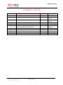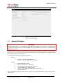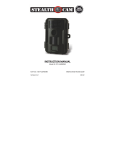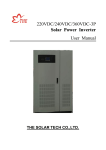
1
WM4 User Manual ALCOLIZER WALL MOUNT 4 USER MANUAL Disclaimer – External Documents The BAC reading obtained by correct use of this device is only considered accurate at the time of testing. Great care has been taken to ensure the accuracy of each reading. Neither the manufacturer, the distributor, nor the owner accepts liability or responsibility due to any action or claim arising from the reading produced by this device, whether used correctly or incorrectly. © Alcolizer Technology 2015 PD-PM-WM4 USER MANUAL-3.1 [26.03.15] WM4 User Manual TABLE OF CONTENTS 1. INTRODUCTION ............................................................................................................. 5 2. DESCRIPTION OF WM4 ................................................................................................. 5 2.1. Variants .................................................................................................................. 5 2.2. Accessories ............................................................................................................ 6 2.3. Specifications ......................................................................................................... 6 2.4. Equipment Overview .............................................................................................. 7 3. ISTALLATION PROCEDURES ..................................................................................... 10 3.1. Installing the Back Plate ....................................................................................... 10 3.2. Mounting and Starting the instrument ................................................................... 12 4. OPERATING INSTRUCTIONS ...................................................................................... 13 4.1. Providing a breath sample .................................................................................... 13 4.2. Analysing the breath sample ................................................................................ 15 4.3. Invalid sample ...................................................................................................... 15 5. OWNER SERVICING .................................................................................................... 16 5.1. Straw replenishment ............................................................................................. 16 5.2. Cleaning ............................................................................................................... 17 6. USER CONTROLS........................................................................................................ 17 6.1. Buttons ................................................................................................................. 17 6.2. Keyboard .............................................................................................................. 18 7. USER INTERFACE ....................................................................................................... 20 7.1. Accessing the user menu ..................................................................................... 20 7.2. Status ................................................................................................................... 20 7.3. Status LED lights .................................................................................................. 22 8. SETTINGS .................................................................................................................... 23 8.1. Instrument Information .......................................................................................... 23 8.2. Alcohol Display ..................................................................................................... 23 8.3. Clock .................................................................................................................... 23 8.4. Authorisation ........................................................................................................ 23 8.5. Authorisation Code Entry ...................................................................................... 23 8.6. Shutdown Instrument ............................................................................................ 24 9. CUSTOM APPEARANCE ............................................................................................. 25 9.1. General Information .............................................................................................. 25 9.2. Background graphics ............................................................................................ 25 9.3. Custom Text ......................................................................................................... 26 9.4. Intervals ................................................................................................................ 26 10. LOGS ............................................................................................................................ 27 10.1. View ..................................................................................................................... 27 10.2. Export ................................................................................................................... 28 11. NETWORKS.................................................................................................................. 29 PD-PM-WM4 USER MANUAL-3.1 [26.06.15] Page 2 of 41 WM4 User Manual 11.1. Configuration ........................................................................................................ 29 11.2. Services ............................................................................................................... 30 12. EMAIL ........................................................................................................................... 31 12.1. Email Settings ...................................................................................................... 31 12.2. Email Reports ....................................................................................................... 33 13. RELAYS ........................................................................................................................ 34 13.1. Hardware .............................................................................................................. 34 13.2. Configuration ........................................................................................................ 35 14. SELF-CHECK ............................................................................................................... 36 15. BREATH TEST AUTHORISATION ............................................................................... 37 15.1. Serial Port Authorisation ....................................................................................... 37 15.2. Wiegand USB device ............................................................................................ 38 15.3. Coin Mechanism Authorisation ............................................................................. 38 16. FACTORY SERVICING AND TROUBLESHOOTING ................................................... 39 16.1. Factory Servicing .................................................................................................. 39 16.2. Field Servicing ...................................................................................................... 39 16.3. Troubleshooting .................................................................................................... 40 17. CALIBRATION .............................................................................................................. 41 PD-PM-WM4 USER MANUAL-3.1 [26.06.15] Page 3 of 41 WM4 User Manual CHANGE STATUS Issue Number Reason for Issue 1.0 Initial Issue 1.1 Date Authority 1 Jun 2014 General Manager New Template 20 Jan 2015 National Service Manager 2.0 New information added 01 Mar 2015 National Service Manager 2.1 Revised template 9 Mar 2015 General Manager 2.2 Released Version 12 Mar 2015 General Manager 3.0 Added Settings, Logs, Relays, Self-Check and Breath Test Authorisation information. 12 Jun 2015 Production Manager 3.1 Released Version 26 Jun 2015 General Manager PD-PM-WM4 USER MANUAL-3.1 [26.06.15] Page 4 of 41 WM4 User Manual 1. INTRODUCTION This User Manual details the operation of the Alcolizer Technology Wall Mount 4 (WM4) alcohol breath testing instrument. WM4s come in a variety of models with various configurations. Depending on the type of WM4 purchased, this manual may contain information that is not applicable to your model. This manual is divided into various Sections and Sub-sections to enable the user to access the required information with ease. It includes Warnings, Cautions and Notes applicable to the WM4 machine and a Specifications table. WARNING If the supply cord is damaged, a risk of electrocution exists. It must be replaced by the manufacturer, an approved service agent or similarly qualified persons. Should the instrument be damaged or require servicing, contact Alcolizer on 1300 789 908. CAUTION This appliance is not intended for use by persons (including children) with reduced physical, sensory or mental capabilities, or lack of experience and knowledge, unless they have been given supervision or instruction concerning the use of the appliance by a person responsible for their safety. Ensure children do not play with the machine. Do not disassemble. The machine contains no owner reusable parts. 2. DESCRIPTION OF WM4 2.1. Variants The Wall Mount 4 is available in the following model types: Standard, Standard with coin operation, Standard with key pad and camera, Standard with key pad, camera and cellular (mobile connectivity and WiFi through a GSM module), All variants have internet connectivity through an Ethernet port or GSM module in the case of the cellular version. Some variants include a mix of the types listed above. Depending on the specific user requirements, machines can include unique configurations. Should any concerns over the configuration be noted, contact your Alcolizer Technology representative for further advice. PD-PM-WM4 USER MANUAL-3.1 [26.06.15] Page 5 of 41 WM4 User Manual 2.2. Accessories The Wall Mount 4 has available the accessories below but not limited to: Alert System (LED Strobe and Buzzer), Card Reader, iPad Connectivity, Printer, Wiegand. Some accessories require specific installation and operating instructions. Please, contact your Alcolizer Technology representative for further advice. 2.3. Specifications The basic specifications of the WM4 are detailed in Table 1. Table 1 – Wall Mount 4 Specifications Item Specification Dimensions 560mm (H) x 390mm (W) x 190mm (D) Weight 18kg Power 100-240V ∿50/60Hz 75W Housing Steel construction Sensor Alcohol specific electrochemical fuel cell Response Time Within 3-5 seconds for a 0.100g/100ml BAC reading Display - Type 25cm (10”) colour graphics LCD Operating Temp 0 to 50°c Measurement Display 4 Digits (x.xxx g/100ml) Detection Range 0.000 - 0.500 g/100ml Accuracy Absolute accuracy to better than +/- 0.005 g/100ml (BAC) Sample volume 1.2 Litres Calibration Daily self-calibration for 12 months (internal certified gas) Warranty 24 months Certifications AS3547 – 1997: Breath alcohol testing devices for personal use, AS/NZS 60335.1 – 2011: Household and similar electrical appliances - Safety General requirements, EMC: Conducted & Radiated emissions PD-PM-WM4 USER MANUAL-3.1 [26.06.15] Page 6 of 41 WM4 User Manual 2.4. Equipment Overview The WM4 is a wall mounted or free standing (on an approved stand) alcohol breath testing machine. It is designed for high volume, fixed point commercial and industrial alcohol breath testing applications. The Alcolizer WM4 incorporates innovative and pioneering technology with features providing speed and efficiency for all testing requirements. It incorporates a self-recalibration feature providing accuracy and reliability from its own internal NATA Certified Gas Standard every 24 hours. Figure 1 to Figure 4 describe the main parts the WM4. 10” Display screen Straw receptacle sample port Straw dispenser Figure 1 – Front View (Typical) PD-PM-WM4 USER MANUAL-3.1 [26.06.15] Page 7 of 41 WM4 User Manual Serving data decal Key lock Information decal Serial number decal Figure 2 – Left side and right side PD-PM-WM4 USER MANUAL-3.1 [26.06.15] Page 8 of 41 WM4 User Manual Gas bottle certification document Certified calibration reference gas cylinder On/off gas valve Function buttons – refer paragraph 6.1 USB ports x 4 – refer paragraph 6 Straw box Figure 3 – Rear view – Internal PD-PM-WM4 USER MANUAL-3.1 [26.06.15] Page 9 of 41 WM4 User Manual Mounting holes Male lift off hinge Mounting holes Figure 4 – Back Plate 3. ISTALLATION PROCEDURES WARNING The WM4 weighs 18kg. Use two man lift procedures when mounting and removing from back plate. When the unit is open or not installed on the back plate, electrical components are exposed. Ensure electrical power is isolated at the supply power point whenever the unit is open unless specifically required for special troubleshooting requirements. 3.1. Installing the Back Plate 3.1.1. Mounting location When choosing a suitable mounting location, the following factors should be considered: The instrument must be mounted on a wall or structure that can support the weight of the instrument. The instrument must not be exposed to rain or water. The instrument should be mounted near to a mains power socket to allow for easy connection. Under extremely heavy use, the instrument could discharge excess saliva from a vent on the bottom of the main unit. Avoid mounting the instrument above anything that could be affected by moisture (e.g. power points). The instrument must not be exposed to extreme temperatures outside of the defined operating range. PD-PM-WM4 USER MANUAL-3.1 [26.06.15] Page 10 of 41 WM4 User Manual 3.1.2. Mounting height and position The instrument must be mounted and positioned at a height to accommodate the majority of users and in such a way to allow access to the key lock and to allow the machine to swing open. Refer to Figure 5 for the appropriate mounting dimensions of the back-plate. Figure 5 – Back Plate mount location 3.1.3. Mounting instructions Mount the back plate in accordance with the following procedures: a. Unpack and remove the instrument from the packaging. Unlock the instrument and remove the back plate from the unit. b. Choose a suitable mounting site as described previously. c. Bend or remove any cutaway portions on the back plate to permit cable access if necessary (refer Figure 6). PD-PM-WM4 USER MANUAL-3.1 [26.06.15] Page 11 of 41 WM4 User Manual Cut-out portion Figure 6 – Cut-out portion on back plate d. Fix the back plate to the wall using masonry fixing hardware (e.g. medium duty anchors). The fixings should be strong enough to support the instrument (at least 20kg) and any incidental loading such as a person leaning or pulling on the instrument. WARNING Do not use adhesives (Liquid Nails) as the method of fixing as these are not considered to be a reliable or safe fixing means for the WM4. 3.2. Mounting and Starting the instrument 3.2.1. Mounting Mount the instrument in accordance with the following procedures: 3.2.2. a. Using an assistant, hang the instrument onto the back plate by aligning the male lift off hinge pins on the back plate with the main instrument lift of female hinge tubes. b. Confirm the instrument swings effectively and does not impact any other fixtures. c. Route any cables to avoid damage and trip hazards. d. Visually check that there are no loose components from transportation. e. Remove any packing materials. f. Remove the screen protector film from the front of the display screen. g. Load straws into the straw box, ensuring that the straws are lying freely within the box. Initial starting Perform the following steps for the initial start-up: a. Turn the reference gas on by rotating the on/off valve one full turn anti-clockwise (refer Figure 7). NOTE The gas bottle certification documents (attached to the gas bottle neck) must remain with the bottle (refer Figure 3). PD-PM-WM4 USER MANUAL-3.1 [26.06.15] Page 12 of 41 WM4 User Manual Gas on/off valve Figure 7 – Turning the reference gas on b. Close and lock the instrument. c. Plug the power cord into a power outlet and turn the power on. d. Plug any other cords into their devices. The instrument will take several minutes to start up and will take a further 10 minutes to perform its first self-calibration. After this, the instrument will be calibrated and ready for use. 4. OPERATING INSTRUCTIONS 4.1. Providing a breath sample NOTE For accurate results, food or drink must not be consumed for the 15 minutes prior to testing. The BAC can continue to rise for up to two hours after the cessation of drinking, care should be taken if a result close to the designated BAC limit is indicated. It can take 10 hours or more for the BAC level to return to zero after a high BAC level has been reached, in such cases further tests should be carried out later in the day or the following morning. Perform a breath test in accordance with the following procedures: a. Ensure the instrument is ready to take a sample. This is indicated with a welcome screen and instructions on how to provide a breath sample (refer Figure 8). There may be a specific customer welcome screen. b. Take a straw from the straw holder. c. Place straw in the sample port (refer Figure 8). PD-PM-WM4 USER MANUAL-3.1 [26.06.15] Page 13 of 41 WM4 User Manual CAUTION Never inject fluids into the sample port. This could render the instrument inaccurate for subsequent tests or temporarily disable it. Figure 8 – Insert straw and blow d. Start blowing and continue blowing until the progress bar reaches 100% (refer Figure 9). During the blow sequence, a beeping sound will be heard. Figure 9 – Keep blowing e. Stop blowing when the display shows Stop Blowing. This will also be indicated by a long beep (refer Figure 10). PD-PM-WM4 USER MANUAL-3.1 [26.06.15] Page 14 of 41 WM4 User Manual Figure 10 – Stop Blowing 4.2. Analysing the breath sample The instrument will perform an analysis and then display the result (refer Figure 11). Figure 11 – BAC displayed If the BAC detected is zero, the display will be green; from zero to 0.050g/100ml, the display will be orange and for readings above 0.050g/100ml, the display will be red. The result will continue to be displayed while the instrument resets itself ready for the next test. For zero readings this will typically be about five seconds. 4.3. Invalid sample The invalid blow screen is displayed if the user stops blowing before 1.2 litres is recorded, they blow too softly or blow too hard (refer Figure 12). PD-PM-WM4 USER MANUAL-3.1 [26.06.15] Page 15 of 41 WM4 User Manual Figure 12 – Invalid blow If the blow is invalid, cease blowing, wait until the Insert Straw and Blow screen is displayed and then provide another sample. 5. OWNER SERVICING 5.1. Straw replenishment Should the straw bin require replenishing, perform the following procedures: a. Turn the WM4 off at the power point. b. Open the instrument by unlocking it and swinging it open. c. Open the straw bin by lifting the latch and removing the cover by manoeuvring it forward (refer Figure 13). Straw bin lid Straw bin lid latch Figure 13 – Opening straw bin PD-PM-WM4 USER MANUAL-3.1 [26.06.15] Page 16 of 41 WM4 User Manual d. Load in new straws ensuring they lie loosely and tidily in the bin (refer Figure 14). Figure 14 – Loading in straws 5.2. e. Reinstall the bin lid by aligning it in the rear slots and latching it down. Ensure it is closed securely. f. Close and lock the instrument. g. Turn the power back on. The instrument will conduct internal checks and then be ready for use in a few minutes. Cleaning The outside of the machine can be cleaned by wiping it over with a soft moist cloth followed by a soft dry cloth. Do not use harsh cleaning agents, abrasive cleaning pads or chemicals. 6. USER CONTROLS 6.1. Buttons WARNING When the unit is open or not installed on the back plate, electrical components are exposed. The following steps require the user to open the WM4 with power applied. During the procedures ensure only the buttons mentioned are activated. Do not come in contact with any exposed components. Inside the WM4 are buttons which can be used to access certain menus during setup and fault finding. Users should not access the machine and press these buttons unless specifically requested to by instructions in this manual or verbally when in contact with your Alcolizer Technology technical representative. Access the buttons by unlocking the WM4 and swinging it open. The buttons are located on the main circuit panel (refer Figure 3). Refer to Figure 15 for location of the buttons. PD-PM-WM4 USER MANUAL-3.1 [26.06.15] Page 17 of 41 WM4 User Manual Figure 15 – Location of function buttons The only buttons that users need to operate are FN1, FN4 and OFF. Do not touch the other buttons. The buttons have the following functions: FN1: Show/hide the Status page. Does the same as pressing F1 on the keyboard. FN4: Save the event log to USB flash memory. Does the same as pressing F4 on the keyboard. OFF: Power-off and power-on the instrument. If the instrument is running, press once to power down. If the instrument is powered off, press once to start up. WARNING Pressing and holding the OFF button may cause irreparable damage to the instrument and should only be performed by an Alcolizer Technician. 6.2. Keyboard WARNING When the unit is open or not installed on the back plate, electrical components are exposed. The following steps require the user to open the WM4 with power applied. During the procedures ensure only the ports mentioned are touched. Do not come in contact with any other exposed components. A standard 101 style keyboard (with a standard USB connection) or a wireless keyboard can be connected to the WM4 to access certain menus during setup and fault finding. Users should not PD-PM-WM4 USER MANUAL-3.1 [26.06.15] Page 18 of 41 WM4 User Manual access the machine and attach a keyboard unless specifically requested to by instructions in this manual or verbally when in contact with your Alcolizer Technology technical representative. Access the USB ports by unlocking the WM4 and swinging it open. There are four ports located on the main circuit panel (refer Figure 3). Refer to Figure 16 for location of the ports. CAUTION Use care when inserting the connector to the port to ensure neither are damaged. Wireless keyboard connection Keyboard connection with cable Figure 16 – Keyboard USB ports (cable and wireless) Once the keyboard is connected, access to the various menus is available. The keyboard functions are as follows: F1: Toggle Status screen F4: Save event log Alt: toggle instrument configuration menu Esc: Toggle instrument configuration menu Alt+up: Switch to previous configuration page Alt+down: Switch to next configuration page Alt+left: Switch to previous tab or page Alt+right: Switch to next tab or page Ctrl+Alt+P: Write screen shot to USB NOTE Use only the left Alt key. The right Alt key has no function. The spacebar has the same functionality as the Enter key in normal usage. When entering data, use the spacebar not the Enter key. PD-PM-WM4 USER MANUAL-3.1 [26.06.15] Page 19 of 41 WM4 User Manual 7. USER INTERFACE 7.1. Accessing the user menu To access the User Menu, perform the following steps (refer Figure 17): a. Connect a keyboard in accordance with paragraph 6.2. b. Press the F1 key to access the WM4 User Menu area. c. Press the left Alt key to bring up available menu choices. d. Press the down key and move down to the required menu (e.g. Settings). e. Press left Alt to hide the menu and give clear access to the selected page. Figure 17 – WM4 User menus (Settings) page NOTE A mouse can be used to operate the various User Interface menus. Connect the mouse or mouse wireless connector in the same manner as the keyboard. 7.2. Status The status page will provide a variety of information for the user (refer Figure 18): 7.2.1. Identification Serial Number: A number that uniquely identifies the WM4. This number is also printed on the side panel safety label located on the side of the instrument. Software Version: The version of software running in the WM4 (e.g. ac-9.1). PD-PM-WM4 USER MANUAL-3.1 [26.06.15] Page 20 of 41 WM4 User Manual 7.2.2. Status Items The status items page will provide a variety of information for the user. Each status item is classified as one of the following. Fault: The instrument has encountered a critical error and is unable to perform breath analysis. The fault must be manually cleared (or repaired) by an authorised Alcolizer service technician on 1300 789 908. Alert: The instrument has encountered a temporary condition that is preventing the unit from performing breath analysis. For example, liquid detected in breath sample system. The alert will clear automatically. Breath analysis is disabled if an alert is active. Warning: The instrument has discovered a problem but is able to function normally (for the time being). For example, calibration gas low. Breath analysis is enabled if a warning is active. Notice: Information that might be useful to a technician but in no way represents a problem with the instrument. Breath analysis is enabled if a notice is active. Disabled: Breath testing is disabled for a reason other than a fault or alert. For example, no reference gas. NOTE Status items are displayed to the user on the Status page in the instrument's current language. Each status item also includes a unique code to help identify the status item when the instrument is in a different language. 7.2.3. Network Connections The Network Connections area shows status information for the WM4 Ethernet port. A valid network connection is not required for the instrument to operate correctly, however if a WM4 has an internet connection the date and time will be automatically adjusted. If connected to a valid network the instrument's IPv4 address is displayed (e.g. 192.168.15.133). If not connected to a valid network, none available is displayed. For further information regarding the Network refer to paragraph 11. PD-PM-WM4 USER MANUAL-3.1 [26.06.15] Page 21 of 41 WM4 User Manual Figure 18 – Status page 7.3. Status LED lights WARNING When the unit is open or not installed on the back plate, electrical components are exposed. The following steps require the user to open the WM4 with power applied. Do not come in contact with any exposed components. The WM4 status can also be assessed by viewing the status LEDs on the main circuit board while the unit is on. Only STAT4 and STAT5 LEDs display status. STAT4 displays the Log Export State and STAT5 displays the WM4 State. The LEDs various displays indicate the following: STAT4: LED Off - Log save not in progress LED On - Log save triggered or in progress LED fast blinking – Reset LED two short pulses – Starting up LED continuous one short pulse – Running LED steady blinking – Shutting down LED on – Shut down (power still connected and On) LED off – Unit Off STAT5: If any other blinking patterns are noticed, contact your authorised Alcolizer service technician on 1300 789 908. PD-PM-WM4 USER MANUAL-3.1 [26.06.15] Page 22 of 41 WM4 User Manual 8. SETTINGS The settings page provides the configuration options available for the user (refer Figure 21): 8.1. Instrument Information The instrument information feature allows a customer to add user-specific descriptions of the instrument (e.g. “Site 13, Gate B”). This description is included in all email reports by default. 8.2. Alcohol Display The alcohol display feature specify how alcohol results are displayed by the instrument. Numeric: Show the specific alcohol content detected Alcohol Detected: Only indicate whether or not alcohol was detected in the sample. 8.3. Clock The date and time can be set manually or automatically if the instrument is connected to the internet (via the wired Ethernet connection). There is no need to manually adjust it if connected to the internet. In order for the WM4 to display the correct date and time, the time zone must be set correctly. The display format is set to YYYY-MM-DD HH:MM:SS and cannot be changed. NOTE There is a 9V battery installed in the instrument to retain the date and time for several years while disconnected from mains power. 8.4. Authorisation The authorisation feature when enabled prevents the WM4 from performing a breath test until it has received authorisation from an external agent (e.g. remote serial device, keypad, Coin Mechanism, etc). Enabled: Check to enable breath test authorisation. For further information about breath test authorisation refer to paragraph 15. Expiry Time: Once a single breath test is authorised, the test analysis must be completed within this time or the authorisation expires and a new authorisation is required. 8.5. Authorisation Code Entry These settings are only accessible if breath test authorisation is enabled. They apply to authorisation code entry using a USB input device (keyboard, swipe card reader, etc). Enabled: Check to allow authorisation codes to be entered using a USB input device. Expiry Time. Amount of time a user has to accept the input code (by pressing ENTER) before the code entry expires and the user must start again. Display. Specify how password characters entered on the screen should be displayed (refer Figure 19). PD-PM-WM4 USER MANUAL-3.1 [26.06.15] Page 23 of 41 WM4 User Manual Figure 19 - Code Entry Screen 8.6. Shutdown Instrument When the Shutdown Instrument button is pressed the following options are presented to the user (refer Figure 20): Reboot: Restart the instrument. Power Off: Shutdown the instrument so that mains power can be removed. This method or the OFF button on the PCBA localised internally in the WM4 are the only two ways to correctly power off the instrument. Figure 20 - Shutdown PD-PM-WM4 USER MANUAL-3.1 [26.06.15] Page 24 of 41 WM4 User Manual Figure 21 - Settings 9. CUSTOM APPEARANCE 9.1. General Information The front screen can be customised to suit specific customer requirements. Various images and messages can be displayed. The supported image formats are PNG, BMP, and GIF, however PNG is recommended. The available space for the image is 800 pixels wide and 234 pixels high. To save time in uploading a background image, have only one image on the storage device. 9.2. Background graphics To import a background graphic, proceed as follows: a. Connect a keyboard and access the User Menu in accordance with the procedures at paragraph 7.1. b. From the User Menu, access the custom appearance screen by scrolling down to Custom Appearance and pressing space bar. The Custom Appearance screen will appear. c. Tick the Show Idle Background Image box (refer Figure 22). d. Inset a USB storage device (thumb drive) with the desired image into an available USB port (refer Figure 16). e. Click on the Select Image button. f. Select the required graphic from the Select Image page and click OK. g. That image will now appear on the screen. PD-PM-WM4 USER MANUAL-3.1 [26.06.15] Page 25 of 41 WM4 User Manual 9.3. Custom Text The Elements area allows customisation of user interface text for a variety of breath testing screens. Display custom text on the screen as follows: a. Connect a keyboard/mouse and access the User Menu in accordance with the procedures at paragraph 7.1. b. From the User Menu, access the custom appearance screen by scrolling down to Custom Appearance and pressing space bar. The Custom Appearance screen will appear. c. Tick the Use Custom Text box in the elements field. d. Select the desired screen. e. Type the required text in the free text field for the highlighted screen. f. To activate a free text of a specific screen, tick the box beside the screen name. Figure 22 – Custom Appearance - Custom Text 9.4. Intervals It is possible to adjust the timings for some screen display intervals. Descriptions of how the timings apply to the display are presented for each adjustable interval (refer Figure 23). PD-PM-WM4 USER MANUAL-3.1 [26.06.15] Page 26 of 41 WM4 User Manual Figure 23 - Custom Appearance – Intervals 10. LOGS 10.1. View The View contains the log records which consist of one or more pieces of information. Each record will show a unique log record id entry followed by the date and time and a brief description of the logged event. Selecting an item in this panel a more detailed view of the selected log record is also presented below the list of log records (refer Figure 24). NOTE If the instrument has a camera installed and enabled then there will also be a photo panel showing any photos associated with the selected log record. If the panel does not have focus it will act as a slideshow over the available images. If the panel has focus the arrow keys can be used to navigate to a specific photo. The log record can contain any of the following events: Calibration Failed. Instrument calibration was not successful. Calibration Gas Bottle Changed. The calibration gas bottle was changed and service life Calibration Successful. Instrument calibration was successful. Result. The result of a breath test. System Shutdown. The instrument was shut down (to be powered off or rebooted). was reset. PD-PM-WM4 USER MANUAL-3.1 [26.06.15] Page 27 of 41 WM4 User Manual System Started. The instrument was started. System Time Changed. The wallmount's time or date was changed. Fault Cleared. A fault status item cleared. Fault Set. A fault status item set. Alert Cleared. An alert status item cleared. Alert Set. An alert status item set. Warning Cleared. A warning status item cleared. Warning Set. A warning status item set. Notice Cleared. A notice status item cleared. Notice Set. A notice status item set. Breath Analysis Block Set. Data analysis is disabled. Breath Analysis Block Cleared. Data analysis enabled. Fuel Cell Changed. Fuel cell changed, configuration and data was reset. Figure 24 - Logs - View 10.2. Export Logs can be exported from the instrument into USB flash drive both by using the Save button on the Export page or automatically when a USB flash drive is inserted if configured to do so (refer Figure 25). Alternatively, the records can be exported by inserting a USB flash drive and pressing FN4 on the PCBA. Refer to paragraph 6.1 to see button location. PD-PM-WM4 USER MANUAL-3.1 [26.06.15] Page 28 of 41 WM4 User Manual These are the formats which logs can be exported: CSV: Comma Separated Values with one log record per row and record fields separated by commas within rows. This is suitable for import into most spreadsheet applications. JSON: JavaScript Object Notation in a format suitable for integration with automated systems. It is also possible to erase the current event log records on the device using the Erase Event Log button. Figure 25 - Logs – Export 11. NETWORKS 11.1. Configuration The configuration panel provide general information about the network connection and device. 11.1.1. Network Setup The network IPv4 Configuration can be set to obtain an IP address automatically or use a static IP address. Establish an internet connection as follows: a. Connect the WM4 to an internet receptacle via the Ethernet cable. b. Connect a keyboard/mouse and access the User Menu in accordance with the procedures at paragraph 7.1. c. From the User Menu, access the network configuration screen by scrolling down to Network and pressing space bar. The Network Configuration page will appear (refer Figure 26). PD-PM-WM4 USER MANUAL-3.1 [26.06.15] Page 29 of 41 WM4 User Manual d. Complete the Configuration page with the required details to establish the network connection if a Static IP address will be used or select “Obtain an IP address automatically”. Figure 26 – Network Configuration 11.1.2. GSM Set up The WM4 keypad + camera + cellular model includes a GSM (Global System for Mobile Communications) modem with a SIM card that must be activated as part of the set up procedure. The SIM card activation code is located inside the WM4 device. This model does not require changes to the network configuration since it comes set from the factory. 11.2. Services 11.2.1. Authorisation Over Network The americium protocol (refer paragraph 15.1.1) can be enabled on a TCP/IP port to allow breath test authorisation over the network. The operation of this feature is identical to the protocol operating over the serial ports. There is no limit to the number of network clients that can connect simultaneously. Refer to Figure 27. Enabled: Whether the instrument accepts network connections on the specified port. This is disabled by default. Port: The TCP port number. 11.2.2. Alcolizer Portal The Alcolizer Portal enables your device to post logs and status information from the instrument to the portal which is a Cloud service. This portal provides a real-time solution with analytical and statistical tools. PD-PM-WM4 USER MANUAL-3.1 [26.06.15] Page 30 of 41 WM4 User Manual NOTE Please, contact your Alcolizer Technology representative for further information about Alcolizer Portal. Figure 27 - Network Service 12. EMAIL 12.1. Email Settings The WM4 is equipped for forwarding email notifications of status and logs. To configure the email function, perform the following steps: a. Establish an internet connection via the Ethernet cable. This step is not required if the instrument has a GSM modem. b. Connect a keyboard/mouse and access the User Menu in accordance with the procedures at paragraph 7.1. c. From the User Menu, access the email configuration screen by scrolling down to Email and pressing space bar. d. The email screen has two tabs: Settings and Reports. 12.1.1. Settings – Mail template The Mail Template panel allows configuration of the format and recipients of emails sent from the instrument. It features the following settings fields (refer Figure 28): Default Recipients: A list of email recipients for emails produced by the instrument. e.g. [email protected]. Add additional recipients as required separating each with a space. PD-PM-WM4 USER MANUAL-3.1 [26.06.15] Page 31 of 41 WM4 User Manual Subject Prefix: Text to be prepended to the subject line of emails produced by the instrument. It is also possible to use text replacement allowing real data to be inserted into the text when the email is sent. Email Footer: Text to be appended to the body of emails produced by the instrument. It is also possible to use text replacement allowing real data to be inserted into the text when the email is sent. Figure 28 – Email Settings 12.1.2. Settings – Mail server The Mail Server panel allows configuration of the email account used by the instrument to send emails. This must be a valid email account as it would be configured in a desktop email program. It features the following settings fields (refer Figure 29). Username: The username (typically an email address) used to log into the SMTP server. Password: Password associated with the specified username. Pressing the password button clears the current password and shows a text editor to enter a replacement password. The password characters are obscured by default; press the “eye” icon to temporarily display the password characters. Hostname: URL of the SMTP server (e.g. smtp.gmail.com). Port: The TCP/IP port number used by the SMTP server. Leave blank to use a default value. Use SSL: If enabled then use secure sockets layer to connect to the SMTP server. PD-PM-WM4 USER MANUAL-3.1 [26.06.15] Page 32 of 41 WM4 User Manual Figure 29 – Mail Server 12.1.3. Test Mail The Test Mail panel allows sending a test email from the system confirm email settings and provide feedback on any issues the instrument has sending emails. Activating Send will initiate a test email with the current configuration. The Test Mail panel will then report the status of sending the email and if it fails indicate information about how sending the test email failed. Due to the very long time out periods specified for email configuration if there is an issue with the Mail Server settings it can take a very long time for the test email to fail and this can also block further tests emails being sent until the time out for the previous email has sent. 12.2. Email Reports 12.2.4. Breath Test Results The instrument can be configured to send an email detailing the result of a breath test. This can be done for both zero and positive results. If instrument authentication is enabled, the report can also include information about previous breath tests from the same authentication code (refer Figure 30). 12.2.5. Instrument Status Notification about changes in instrument status can be sent from the instrument for various types of status information. The report includes information on all currently active status items, not just the status item that changed state (refer Figure 30). The status options are: Faults (Permanently Out of Order) – send an email if a fault is raised or cleared. Alerts (Temporarily Out of Order) – send an email if an alert is raised or cleared. Warning – send an email if an alert is asserted or cleared. Notice – send an email if a notice is asserted or cleared. 12.2.6. Event Log Report The instrument can be configured to send periodic emails containing log information for the given period. The interval for the report can be configured from hourly through to monthly and the day or hour the report will occur on is dependent on the start date (refer Figure 30). For example: The current date is the 3rd of October 2013. The Start Time chosen is on the 29th of September 2013, 12 noon. The Report Interval is Weekly. PD-PM-WM4 USER MANUAL-3.1 [26.06.15] Page 33 of 41 WM4 User Manual The next email will be sent on the 6th of October 2013, 12 noon. Figure 30 – Email Reports 13. RELAYS The WM 4 is equipped with three relay outputs on the circuit board and their outputs can be configured to trigger in response to a breath test result. To access the Relays Menu refer to paragraph 7.1. If a relay output is enabled the relay is triggered for the specified duration if the breath test result is greater than or equal to the minimum value and less than the maximum value. The relay outputs are independent of each other. The minimum and maximum values can overlap such that one, two, or three relays can be triggered simultaneously. If a new breath test result is calculated while a relay output is asserted from the previous test, the relay takes the value required by the new test. 13.1. Hardware The relays outputs are labelled on the circuit board as Relay1, Relay2 and Relay3 (refer Figure 31). Each relay output has three terminals: COM: Common connection. NC: Normally Closed, the COM/NC circuit is closed (passes current) when the relay is not triggered and open when the relay is triggered. NO: Normally Open, the COM/NO circuit is open when the relay is not triggered and closed (passes current) when the relay is triggered. PD-PM-WM4 USER MANUAL-3.1 [26.06.15] Page 34 of 41 WM4 User Manual Figure 31 - Relays - Installation 13.2. Configuration There are three relays available and their behaviour can be configured on the Relays page (refer Figure 32). For each relay the following properties can be configured: Enabled: If checked indicates that the relay should respond to breath test results and enables remaining configuration items for the relay. Min: If a result is greater than this value the relay should turn on for the configured duration. If the minimum value is 0.00 the result should turn on if the value of the result is greater than or equal 0.00. Max: If a result is less than this value the relay should turn on for the configured duration. If the maximum value is 0.00 the result should turn on if the value of the result is less than or equal 0.00. Duration: If the relay is enabled and a breath test result falls within its configured range, the relay should fire for a number of seconds equal to the configured duration. The Relay Status indicates if the relay is currently ON or OFF. There are three buttons on this page that briefly activates the relays. NOTE It is possible for breath test results near a configured value for the relays to act differently depending on whether the actual value was slightly above or below the displayed value. This is due to the nature of the analog input from the fuel cell and possible rounding behaviour below the precision of the displayed value. In this situation the instrument will not activate two relays in the situation where one relay shares a nonzero maximum with the minimum value from another relay. PD-PM-WM4 USER MANUAL-3.1 [26.06.15] Page 35 of 41 WM4 User Manual Figure 32 – Relays 14. SELF-CHECK This page allows running some automated self-checks of the instrument to validate the instrument configuration and behaviour (refer Figure 33). Each test indicates whether it has been recently tested and lists a title as well as provides a description of what the test does. One, many, or all tests can be run. Some tests require a degree of user interaction and if this occurs instructions will appear on the screen indicating how to proceed. PD-PM-WM4 USER MANUAL-3.1 [26.06.15] Page 36 of 41 WM4 User Manual Figure 33 - Self-Check 15. BREATH TEST AUTHORISATION Breath test authorisation is a feature that prevents the wallmount from performing a breath test until it has received authorisation from an external agent (remote serial device, keypad, etc). The authorising agent sends a code to the wallmount that allows the wallmount to execute a single breath test. Once the test is performed the authorisation code and authorisation source is logged with the breath test result in the event log and the wallmount waits for authorisation to perform further tests. If a breath test is not performed within a timeout period the authorisation expires and the wallmount must receive a new authorisation code to perform further tests. Authorising agents connect to the wallmount through authorisation channels. An authorisation channel is a combination of a physical connection (serial port, ethernet port, etc) and a software protocol operating over that physical connection. The following authorisation channels are supported depending on model being used: Two RS-232 serial ports (Serial 1 and Serial 2) running the americium serial protocol. An attached Wiegand USB device running the Wiegand serial protocol. Any number of direct network connections running the americium serial protocol. HID input device attached to a USB port (keyboard, card reader, etc). The coin mechanism hardware. 15.1. Serial Port Authorisation The two RS-232 serial ports are activated with the americium serial protocol (v2) at all times, whether test authorisation is enabled or not. This means that all breath test results are sent by the wallmount on both serial ports. PD-PM-WM4 USER MANUAL-3.1 [26.06.15] Page 37 of 41 WM4 User Manual If authorisation is enabled then an agent can send authorisation codes to the wallmount on either serial port. The instrument also supports Wiegand based test authorization, if enabled in production. 15.1.1. Americium Serial Protocol The americium serial protocol operates on both serial ports with the following settings: Protocol version: am-spec-02 Date/Time: local time (not UTC) Please contact your Alcolizer Technology representative for further advice. 15.2. Wiegand USB device The Wiegand support operates via USB serial connections and allows a test to be authorized via a Wiegand card reader. 15.2.1. Direct Network Connection If enabled on the Service page on Networks menu, the americium protocol can operate over a direct network connection on a configurable port number. When a remote device connects to the wallmount it will receive all breath test results according to the americium protocol specification. If breath test authorisation is enabled the remote device can also authorise breath tests. There is no limit to the number of devices that can connect simultaneously to the wallmount. 15.2.2. USB Input Device Authorisation Any HID input device connected to a USB port (e.g. keyboard, card reader, etc) can be used to enter authorisation codes. Legal characters are a-z, A-Z, and 0-9, all other characters are ignored. A carriage return <Enter> is required to submit the data. The <Esc> key is used to cancel data entry. 15.3. Coin Mechanism Authorisation The coin mechanism is a hardware peripheral that attaches to the IN1 trigger input. When this hardware input is closed (e.g. by a coin received in the coin mechanism) a single breath test is authorised. PD-PM-WM4 USER MANUAL-3.1 [26.06.15] Page 38 of 41 WM4 User Manual 16. FACTORY SERVICING AND TROUBLESHOOTING 16.1. Factory Servicing The instrument requires servicing after 365 days of usage by an authorized Alcolizer Technology service technician. This can be performed on site or the unit can be returned to Alcolizer’s facility. NOTE The next service date is defined by the number of days that a WM4 was left ON and performed autocalibrations (365 in total). The system will display a warning message based on the number of autocalibrations. If a device was stored by a customer for six months before it was turned on, the service will happen 18 months after it was dispatched. Contact Alcolizer Technology by any of the following means: Phone: 1300 789 908; Email: [email protected]; or Web: www.alcolizer.com. If the machine is to be returned to Alcolizer, prepare it for shipment in accordance with the following procedures: a. Turn off the instrument and unplug the power cord. b. Unlock and open the instrument. c. Turn the gas off by turning the valve on the gas cylinder. d. Remove straws and tape down straw bin lid. e. Using two-man lifting techniques, lift the instrument off the back plate hinges to and remove it from the wall. f. Pack the instrument into suitable packaging to ensure it is not damaged in freight. 16.2. Field Servicing Contact Alcolizer Technology for further information. PD-PM-WM4 USER MANUAL-3.1 [26.06.15] Page 39 of 41 WM4 User Manual 16.3. Troubleshooting Should the machine malfunction or a warning message appear on the screen, consult Table 2 – Troubleshooting chart in the first instance. Table 2 – Troubleshooting chart Noted Problem Suggested Action The instrument is displaying an Out of Order message on the screen after initial start-up. Ensure the gas bottle valve is open - turn one full turn anticlockwise. Then, press FN2 button on the circuit board to force calibration. The instrument continues to display an Out of Order message on the screen after initial start-up. Wait for the instrument to perform an automatic calibration. Note: this could be performed instantly but may take up to 24 hours. The instrument continues to display an Out of Order message. Contact Alcolizer Technology for further advice: 1300 789 908. The instrument is displaying a warning icon in the bottom left corner. Either there are status items requiring attention (press “FN1” to identify items requiring attention), or the service life may shortly be about to expire. Contact Alcolizer immediately to arrange annual service: 1300 789 908. Locating FN buttons. FN buttons are located on the circuit board as shown in the picture below. PD-PM-WM4 USER MANUAL-3.1 [26.06.15] Page 40 of 41 WM4 User Manual The instrument is displaying “Service Life has Expired”. The instrument’s service life has expired and requires its annual service. Contact Alcolizer immediately to arrange service: 1300 789 908. My instrument is displaying “Liquid Detected”. It is possible that liquid has been blown into the sample port. Ensure liquid is not present and try again. If the problem persists, allow a suitable time period for the liquid to clear itself (anywhere up to 48hrs). You may also attempt to clean the inlet sample port with a dry pipe cleaner. If the problem persists, contact Alcolizer to arrange for servicing: 1300 789 908. Liquid Detected 17. CALIBRATION The WM4 self-calibrates every 24 hours and requires no user calibration. PD-PM-WM4 USER MANUAL-3.1 [26.06.15] Page 41 of 41