1
Previous Menu
Security System
VIA-30PSE
THIS ISSUE INCLUDES THE NEW QED (QUICK ENROLLLMENT
OF DEVICES) PROCEDURE FOR 5800 SERIES TRANSMITTERS
Installation Instructions • Installation Instructions • Installation Instructions
N7225V2 4/97
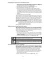
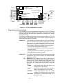
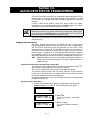
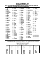
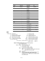
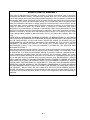
RECOMMENDATIONS FOR PROPER PROTECTION
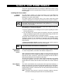
The following recommendations for the location of fire and burglary detection
devices help provide proper coverage for the protected premises.
Recommendations For Smoke And Heat Detectors
With regard to the number and placement of smoke/heat detectors, we subscribe to the
recommendations contained in the National Fire Protection Association's (NFPA) Standard #72 noted
below.
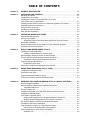
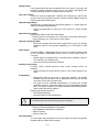
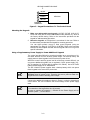
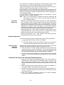
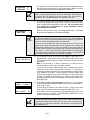
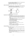
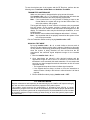
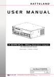
Early warning fire detection is best achieved by the installation of fire detection equipment in all
rooms and areas of the household as follows: For minimum protection a smoke detector should
be installed outside of each separate sleeping area, and on each additional floor of a multi-floor
family living unit, including basements. The installation of smoke detectors in kitchens, attics
(finished or unfinished), or in garages is not normally recommended.
For maximum protection the NFPA recommends that you install heat or smoke detectors in the
living room, dining room, bedroom(s), kitchen, hallway(s), attic, furnace room, utility and storage
rooms, basements and attached garages.
In addition, we recommend the following:
• Install a smoke detector inside every bedroom where a smoker sleeps.
• Install a smoke detector inside every bedroom where someone sleeps with the door partly or
completely closed. Smoke could be blocked by the closed door. Also, an alarm in the hallway
outside may not wake up the sleeper if the door is closed.
• Install a smoke detector inside bedrooms where electrical appliances (such as portable
heaters, air conditioners or humidifiers) are used.
• Install a smoke detector at both ends of a hallway if the hallway is more than 40 feet (12
meters) long.
• Install smoke detectors in any room where an alarm control is located, or in any room where
alarm control connections to an AC source or phone lines are made. If detectors are not so
located, a fire within the room could prevent the control from reporting a fire or an intrusion.
✪
KITCHEN
▲
DINING
✪
✪
✪
BEDROOM BEDROOM
TV ROOM
■
✪
✪
LIVING ROOM
BEDROOM
▲
✪
KITCHEN DINING
■
LIVING ROOM
✪
■
✪
BDRM
BDRM
✪
BEDROOM
✪
▲
■ Smoke Detectors for Minimum Protection
✪ Smoke Detectors for Additional Protection
▲ Heat-Activated Detectors
■
BEDROOM
✪
■
✪
BEDROOM
TO
BR
BEDROOM
■
▲
▲
KTCHN
.
LVNG RM
■
CLOSED
DOOR
GARAGE
BASEMENT
THIS CONTROL COMPLIES WITH NFPA REQUIREMENTS FOR TEMPORAL
PULSE SOUNDING FOR FIRE NOTIFICATION APPLIANCES.
Recommendations For Proper Intrusion Protection
For proper intrusion coverage, sensors should be located at every possible point of entry to a home or
commercial premises. This would include any skylights that may be present, and the upper windows in
a multi-level building.
In addition, we recommend that radio backup be used in a security system so that alarm signals can
still be sent to the alarm monitoring station in the event that the telephone lines are out of order (alarm
signals are normally sent over the phone lines, if connected to an alarm monitoring station).
TABLE OF CONTENTS
Section 1.
GENERAL DESCRIPTION ......................................................................................... 1-1
Section 2.
INSTALLING THE CONTROL .................................................................................. 2-1
Mounting the Cabinet ..................................................................................................... 2-1
Installing the Lock (if used) ............................................................................................ 2-1
Installing the Control's Circuit Board Alone or (if used)
With a 4204, 4219, or 4229 Module................................................................................ 2-1
Installing Control and RF Receiver Circuit Boards Together in the Cabinet................... 2-3
Standard Phone Line Connections ................................................................................. 2-3
Wiring the AC Transformer ............................................................................................. 2-4
Installing the Back-Up Battery ........................................................................................ 2-4
Earth Ground Connections ............................................................................................. 2-4
Section 3.
INSTALLING REMOTE KEYPADS .......................................................................... 3-1
Keypads that May Be Used ............................................................................................ 3-1
Wiring to the Keypads .................................................................................................... 3-1
Wiring Run Chart for Devices Drawing AUX Power From the Control..................... 3-1
Mounting the Keypads .................................................................................................... 3-2
Using A Supplementary Power Supply To Power Additional Keypads........................... 3-2
Preliminary Check-Out Procedure .................................................................................. 3-3
Section 4.
BASIC HARD-WIRED ZONES 5 and 6 .................................................................
Installing the Hard-Wired Zones .....................................................................................
Common Characteristics For Zones 5 and 6 ...........................................................
Wiring Burglary and Panic Devices to Zones 5 and 6 ....................................................
Wiring 4-Wire Smoke/Combustion Detectors on Zones 5 ..............................................
Compatible 4-Wire Smoke/Combustion Detectors...................................................
Programming Hard-Wired Zones....................................................................................
Programming Panic Keys .........................................................................................
Check-Out Procedure for Hard-Wired Zones 5 and 6 ....................................................
Section 5.
WIRED ZONE EXPANSION (4219, 4229) ............................................. 5-1
Installing Zone Expansion Units ..................................................................................... 5-1
Connections and Setup .................................................................................................. 5-1
Programming Wired Expansion Zones ........................................................................... 5-2
Check-Out Procedure for Wired Expansion Zones......................................................... 5-3
Section 6.
WIRELESS (RF) ZONE EXPANSION (5700 & 5800 RF SYSTEMS) ............. 6-1
Wireless Systems Available ........................................................................................... 6-1
Wireless System Operation and Transmitter Supervision .............................................. 6-1
Transmitter Battery Life ............................................................................................ 6-2
Receiver Supervision................................................................................................ ...... 6-2
Installation and Setup of the 4281/5881 Series Wireless Receivers .............................. 6-2
Installing the 5800TM Module......................................................................................... 6-3
5700 Series Transmitter Setup ....................................................................................... 6-3
Setting the DIP Switches on 5700 Series Wireless Transmitters............................. 6-4
Wireless Zone/ID Assignments for 5700 Series Transmitters ................................. 6-4
DIP Switch Tables for 5700 RF System Wireless Devices ............................................. 6-5
Compatible 5700 Series Transmitters ............................................................................ 6-6
Programming the Control For a 5700 Wireless System ................................................. 6-7
Using the House ID Sniffer Mode (5700 Systems) .................................................. 6-7
Zone Programming for 5700 Series Transmitters........................................................... 6-7
Go/NoGo Test .......................................................................................................... 6-9
i
4-1
4-1
4-1
4-1
4-1
4-2
4-2
4-3
4-4
Section 6.
WIRELESS (RF) ZONE EXPANSION (5700 & 5800 RF SYSTEMS), CONT'D
5800 Series Transmitter Setup ..................................................................................... 6-10
5800 Series Transmitter Input Loops ................................................................ ..... 6-10
5800 Series Transmitter Input Types ................................................................ ..... 6-10
Compatible 5800 Series Transmitters .......................................................................... 6-11
Programming the RF Transmitters (5800 RF Systems) ................................................ 6-12
Enrolling 5800 Transmitters Into the System ................................................................ 6-13
Enrolling Through Zone Programming (✱ 56) .......................................................... 6-13
To Either Temporarily or Permanently Remove a Zone From the System
(5800 System) ......................................................................................................... 6-16
Deleting a Transmitter Serial Number From a Zone in ✱ 56 Mode (5800 System) ........ 6-16
Check-out Procedure for Wireless Zones ................................................................ ..... 6-16
Transmitter ID Sniffer Mode (5700 RF Systems Only) ........................................... 6-16
Go/No Go Test Mode (5700 and 5800 RF Systems).............................................. 6-17
Section 7.
RELAY OUTPUT DEVICES ....................................................................................... 7-1
Relay Device Basics ....................................................................................................... 7-1
4204 Relay Modules ....................................................................................................... 7-1
4204 Setup ............................................................................................................... 7-1
Supervision............................................................................................................... 7-1
Programming Options Defined........................................................................................ 7-1
Programming Output Relays........................................................................................... 7-3
Example of Output Relay Programming ................................................................... 7-5
Section 8.
4285 PHONE MODULE ............................................................................................ 8-1
Installing the Phone module............................................................................................ 8-1
General Information .................................................................................................. 8-1
Mounting The Phone module.................................................................................... 8-1
Phone module Wiring ............................................................................................... 8-1
Caller ID Units........................................................................................................... 8-2
Programming The Control For Phone Access ................................................................ 8-4
Checking the Operation of the 4285 Phone module ....................................................... 8-5
Section 9.
EXTERNAL SOUNDERS ............................................................................................ 9-1
Compatible Sounders ................................................................................................ ..... 9-1
Sounder Connections ................................................................................................ ..... 9-2
Programming For External Sounders ............................................................................. 9-2
Testing the Sounder........................................................................................................ 9-2
Section 10.
LONG RANGE RADIO .............................................................................................. 10-1
General Information ................................................................................................ ...... 10-1
Connection .................................................................................................................... 10-1
Programming for Long Range Radio ............................................................................ 10-1
Section 11.
AUDIO ALARM VERIFICATION (AAV) UNIT ..................................................... 11-1
General Information ................................................................................................ ...... 11-1
Wiring Connections ....................................................................................................... 11-1
Programming ............................................................................................................... 11-1
Section 12.
FINAL POWER UP .................................................................................................... 12-1
Earth Ground Connections............................................................................................ 12-1
AC Power-Up ................................................................................................................ 12-1
Connecting the Back-Up Battery ................................................................................... 12-1
Calculating the Battery Size Needed ................................................................ ...... 12-1
Making the Battery Connections ............................................................................ 12-2
Auxiliary Device Current Draw Worksheet .................................................................... 12-2
ii
Section 13.
ALPHA DESCRIPTOR PROGRAMMING ............................................................. 13-1
Assigning Zone Descriptors.......................................................................................... 13-1
Entering Zone Descriptors (in program Menu Mode ✱ 82) ...................................... 13-1
Programming the Descriptors ................................................................................ 13-1
Alternate Method for Programming Zone Descriptors .................................................. 13-3
Adding Custom Words.................................................................................................. 13-4
Alpha Vocabulary List (For Entering Zone Descriptors) ............................................... 13-5
Character (ASCII) Chart ............................................................................................... 13-5
Section 14.
SEQUENTIAL MODE
(For 5800 Series Wireless Transmitters) ......................................................... 14-1
Section 15.
SYSTEM COMMUNICATION ................................................................................. 15-1
Report Code Formats ................................................................................................... 15-1
Table of Contact ID Event Codes........................................................................... 15-3
Communication Programming ...................................................................................... 15-3
Section 16.
TESTING THE SYSTEM .......................................................................................... 16-1
Test Procedure ............................................................................................................. 16-1
To the Installer .............................................................................................................. 16-2
Section 17.
SYSTEM OPERATION ............................................................................................. 17-1
Security Codes ............................................................................................................. 17-1
Installer Code ......................................................................................................... 17-1
Assigning the Master Code .................................................................................... 17-1
Changing the Master Code .................................................................................... 17-1
User Codes ............................................................................................................ 17-1
Duress Code .......................................................................................................... 17-1
Keypad Functions ......................................................................................................... 17-2
General Information................................................................................................ 17-2
Arming Functions ................................................................................................... 17-2
Panic Keys ............................................................................................................. 17-3
4285 Phone module (if used) ................................................................................. 17-3
Relays Outputs (if used)......................................................................................... 17-3
Exit Alarm Displays (if programmed) ...................................................................... 17-3
Trouble Conditions ....................................................................................................... 17-4
General Information................................................................................................ 17-4
"Check" and "Battery" Displays .............................................................................. 17-4
Power Failure ......................................................................................................... 17-4
Other Displays ....................................................................................................... 17-4
Section 18.
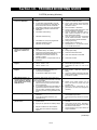
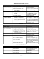
TROUBLESHOOTING GUIDE ................................................................................ 18-1
Contacting Technical Support....................................................................................... 18-3
Section 19.
SPECIFICATIONS & ACCESSORIES .................................................................. 19-1
Specifications ............................................................................................................... 19-1
Accessories (Compatible Devices) .............................................................................. 19-3
Appendix A: REGULATORY AGENCY STATEMENTS................................................ A-1
Appendix B: LIMITATIONS OF THIS ALARM SYSTEM ............................................. B-1
LIMITED WARRANTY ........................................................................ B-2
SUMMARY OF CONNECTIONS DIAGRAM ...................... Inside Back Cover
NOTE: A separate Programming Guide is supplied with this manual.
iii
LIST OF FIGURES
Figure 1.
Installing the Cabinet Lock ........................................................................... 2-1
Figure 2.
Installing The PC Board Alone, or (if used),
With a 4204, 4219, or 4229 Module .............................................................. 2-2
Figure 3.
Installing the PC Board & RF Receiver Together in the Cabinet ................ 2-2
Figure 4.
Standard Telephone Line Connections........................................................ 2-3
Figure 5.
Keypad Connections to the Control Board.................................................. 3-2
Figure 6.
Using a Supplementary Power Supply for Keypads ................................... 3-3
Figure 7.
4-Wire Smoke Detector Connections to Zone 5 .......................................... 4-1
Figure 8.
Wiring Connections, 4219 and 4229 Expanders .......................................... 5-1
Figure 9.
4281, 5881, and 5882 Wireless Receivers (cover removed) ........................ 6-3
Figure 10 . 4204 Connections To Control ....................................................................... 7-1
Figure 11: 4229 Connections to Control........................................................................ 7-2
Figure 12. 4285 Phone module Wiring Connections..................................................... 8-3
Figure 13. Typical Sounder Wiring................................................................................. 9-2
Figure 14. Long Range Radio Connections ................................................................ 10-1
Figure 15. Connection of AAV Unit When Not Using a 4285 Phone module ............. 11-2
Figure 16. Connection of AAV Unit When Also Using a 4285 Phone module............ 12-2
Figure 17. VIA-30PSE Summary of Connections Diagram .................. Inside Back Cover
iv
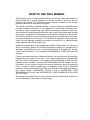
HOW TO USE THIS MANUAL
This manual is written to accommodate both the new and the experienced installer of
Ademco products. A general description of the entire system is located in the first
section of this manual. This includes the various features available and the optional
peripheral devices that the system can support.
This manual is divided into separate sections. A section covering the hardwired zones
provides complete information on the capabilities of each basic hardwired zone,
including its usage, programming, and a checkout procedure. Separate sections are
also provided for each peripheral device that can be used in the system and includes
wiring setup, programming requirements, and a checkout procedure for that device.
The checkout procedures ensure that the specific device is operational in the system
before proceeding to the next section. This “sectional” arrangement is also particularly
useful if you are making an addition to the system at a later time (e.g., adding Wireless
zones, adding a 4285 Phone module, etc.).
Without an understanding of the programming method for this system, you will not be
able to successfully perform the required programming. Before any programming is
attempted, we therefore urge you to read the “Mechanics of Programming” and the
“Data Field Descriptions” in the separate PROGRAMMING GUIDE that has been
supplied.
If you are an experienced user of Ademco products, you may choose to wire and then
program the entire system at one time. If so, refer to “Mechanics of Programming”
and “Data Field Descriptions” in the separate PROGRAMMING GUIDE after the
hardware setup is complete. The separate PROGRAMMING GUIDE contains all of the
information you will need to program the system (including a blank Programming
Form), except for detailed programming for hardwired zones 5 and 6, hardwired
expansion zones, and wireless zones, which are contained in the following sections in
this manual: BASIC HARDWIRED ZONES 5 and 6, HARDWIRED ZONE
EXPANSION (4219, 4229), and WIRELESS (RF) ZONE EXPANSION (5700 & 5800
RF SYSTEMS).
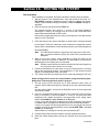
This manual uses various icons to denote critical notes and technical tips to assist you
with the installation of this system (see next page).
v
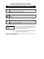
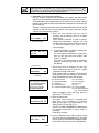
CONVENTIONS USED IN THIS MANUAL
MAIN SECTION TITLES ARE SHOWN IN REVERSE TYPE
UL
These notes include specific information which must be followed if you are
installing this system for a UL Listed application.
These notes include information that you should be aware of before continuing
with the installation, and which, if not observed, could result in operational
difficulties.
This symbol indicates the presence of critical information that, if not observed,
could seriously affect the operation of the system, or could cause damage to the
system. Please read each warning carefully. This symbol also denotes warnings
about physical harm to the installer.
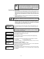
Enter Zn Num.
(00 = Quit)
01
✱00
Many system options are programmed in an interactive menu
mode by responding to Alpha keypad display prompts. These
prompts are shown in a double-line box.
When programming the system, data fields are indicated by a
“star” [ ✱] followed by the data field number.
PRODUCT MODEL NUMBERS: Unless noted otherwise, references to specific model
numbers represent Ademco products.
vi
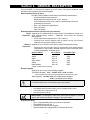
Section 1. GENERAL DESCRIPTION
The VIA-30PSE is a control that supports up to 32 zones, using basic hardwired, wired
expansion, and/or wireless, plus remote keypads.
Basic Hardwired Zones (5 and 6)
Provides 2 basic hardwired zones having the following characteristics:
• 300–500 millisecond response time.
• EOLR supervision supporting N.O. or N.C. sensors.
• Zone 5 supports as many 4-wire smoke or heat detectors as can be
powered from the control.
• Zone 7, 95 and 96 are keypad Panics.
• Zone 8 is Duress.
• Zone 9 is Tamper.
Optional Expansion Zones (30 total, wired and wireless)
Wired Supports up to 8 additional wired zones using a 4219 expansion module, or a
Expansion: 4229 expansion/relay module. Expansion zones have the following
characteristics:
• EOLR supervision supporting N.O. or N.C. sensors.
• 300-500 msec normal response with an option for fast (10–15msec)
response on loop A (first expansion zone).
Wireless Supports up to 30 wireless zones (less if using wired expansion zones).
Expansion: • Requires the use of a 4281 type RF receiver (with 5700 series wireless
transmitters) or 5881 (5882 in Canada) type RF Receiver (with 5800 series
wireless transmitters), as shown below.
Receiver Model
No. of Zones
Transmitter Type
4281L
Up to 4
5700
4281M
Up to 8
5700
4281H
Up to 8
5700
5881L/5882L*
Up to 8
5800
5881M
Up to 16
5800
5881H/5882H*
Up to 30
5800
* 5882L or 5882H used in Canada.
Remote Keypads
Supports up to 4 of any of the following keypads:
Fixed-Word Keypads: 4127*, 4137AD, 6127*, 6128, and 6137.
* These keypads cannot be used if the 4285 Phone module is being used.
Alpha Keypads: 5137AD , 6139 (2-line alphanumeric displays)
6138 (1-line alphanumeric display).
For programming from a keypad, a 5137AD or 6139 2-line Alpha keypad must
be connected (but need not necessarily stay in the system).
Security Codes
•
•
•
One Master code for entire system (user 2). Installer code is user 1.
4 secondary user codes (users 3–6).
One duress code (User 8).
Duress Code: An emergency code which, when used to disarm or arm the
system, will send a silent duress message to the central station .
Keypad Panic Keys
• Up to 3 programmable panic key functions are provided.
• Designated as Zones 95, 96, 7.
• Activated by wired & wireless keypads.
• Reported separately, distinguished by subscriber ID number.
1 –1
Paging Feature
If the paging feature has been programmed for your system, your pager will
respond to certain conditions as they occur in your system, and display code
numbers indicating the type of condition that has occurred.
Quick Arm Feature
“Quick Arm” may be programmed , allowing use of the [#] key in place of the
security code for arming (Quick Arm will not work unless the Master code has
been programmed into the system).
Optional Output Relays
Supports up to 4 relays using one 4204 Relay Module, or 2 relays using one
4229 Zone Expansion/Relay Module.
• Actions programmable to respond to zone activity or manual keypad
entries.
Optional Phone module
Supports the Ademco 4285 VIP Phone Module.
• Provides access to the system via on premises or off-premises phones for
arming, disarming, etc., plus control of relay outputs.
Optional Long Range Radio
• Allows all messages that have been programmed to go to the primary
telephone number to be reported additionally to a 7720 PLUS or 7820
radio.
Alarm Output
Provides a 12VDC, 2 AMP output that can drive the compatible sounders listed
in the EXTERNAL SOUNDERS section (assumes a fully charged battery is
connected) .
• Steady output for Burglary/Panic, or t emporal pulse sounding output for
Fire notification, as required by UL.
• Uses current limiting circuitry for protection.
Auxiliary Power Output
Provides 12VDC, 500mA maximum. Uses current limiting circuitry for
protection.
• Output interrupts for smoke detector reset if 4-wire smoke detectors are
used.
Programming
• Programmed options are stored in electrically erasable, non-volatile
EEROM memory (information can be reprogrammed at any time and will
not be lost in the event of a power loss).
• The system can be uploaded, downloaded, or controlled via an IBM
compatible computer, using either Ademco's V-Link downloading software
(Rev. 4 or higher) or Ademco's Compass Windows downloading software,
and a modem specified by Ademco.
Keypad programming consists of:
• Data field programming.
• Interactive (menu) mode programming.
For programming from a keypad, a 5137AD or 6139 2-line Alpha keypad must
be connected (but need not necessarily stay in the system).
Communication Formats Supported
• Ademco Low Speed (Standard or Expanded).
• Sescoa/Radionics (Standard or Expanded).
• Ademco Express.
• Ademco Contact ID.
Zone Descriptors
You can assign Alpha descriptors to all zones (useful only when using Alpha
keypads and/or the 4285 Phone module).
1 –2
Section 2. INSTALLING THE CONTROL
This section provides instructions for mounting the control cabinet, and
installing the cabinet lock (if used). Also included in this section are instructions
for the following:
• Installing the main PC board (and 4204 Relay Unit, if used).
• Mounting the RF Receiver board (if used) in the cabinet.
• Standard phone line connections.
• Installing the back-up battery in the cabinet.
• Connecting the AC transformer.
• Making earth ground connections.
Mounting the Cabinet
Mount the control cabinet to a sturdy wall using fasteners or anchors (not
supplied), in a clean, dry area which is not readily accessible to the general
public. Four mounting holes are provided at the back of the cabinet.
If an RF Receiver is being used and you intend to mount its PC board within
the cabinet, note the following:
• Do not mount the cabinet on or near metal objects. This will decrease RF
range and/or block RF transmissions from wireless transmitters.
• Do not locate the cabinet in an area of high RF interference (revealed by
frequent or prolonged lighting of the LED in the receiver after it is
operational). Random flicker is OK.
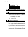
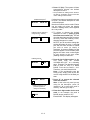
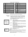
Installing the Lock (if used)
Use an Ademco No. N6277 Cam Lock and No. N6277–1 Push-On Clip
(Retainer Clip).
Note: The cabinet can be closed and secured without a lock by using 2
screws in the cover's edge.
1. Remove the cabinet door. It
RETAINER CLIP
is easily removable for
(NOTE POSITION)
servicing and is easily reinstalled.
2. Remove the lock knockout
from the control cabinet
LOCKED
RETAINER
SLOTS
door. Insert the key into the
RETAINER
CLIP
lock. Position the lock in the
hole making certain that the
latch will make contact with
UNLOCKED
the latch bracket when the
door is closed.
3. Hold the lock steady, and insert the retainer clip into the
CABINET DOOR BOTTOM
retainer slots. Position the
clip as illustrated in order to
Figure 1. Installing the Lock
permit easy removal.
Before installing the cabinet's contents, remove the metal cabinet knock-outs
required for wiring entry. Do not attempt to remove the knockouts after the
circuit board has been installed.
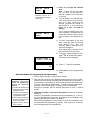
Installing the Control's Circuit Board Alone, or (if used), with a 4204, 4219, or 4229 Relay
Unit
Control's Circuit Board
1.
2.
3.
Hang two long Red mounting clips (provided) on the raised cabinet tabs
(see Detail B in Fig. 2).
Insert the top of the circuit board into the slots at the top of the cabinet.
Make sure that the board rests on the correct row (see Detail A in Fig. 2).
Swing the base of the board into the mounting clips and secure the board
to the cabinet with the accompanying screws (see Detail B in Fig. 2).
2 –1
4204, 4219, or 4229/
Expansion Unit
(if installed in cabinet)
1.
2.
3.
Insert self-tapping screws (provided) in two adjacent raised cabinet tabs.
Leave the heads projecting 1/8".
Hang the unit on the screw heads via two of the slotted holes at the rear of
its housing, as shown in Figure 2.
The expansion unit's cover can be left off if the unit's DIP switch is set with
its position 1 "ON" (to the right) as shown in its instructions. The tampered
cover is necessary for installations outside of the control's cabinet.
CIRCUIT
BOARD
CABINET
DETAIL B
SIDE VIEW OF
LONG MOUNTING CLIPS
CONTROL
CIRCUIT
BOARD
DETAIL A
SIDE VIEW OF
BOARD SUPPORTING SLOTS
NOT
TAMPERED
TAMPERE
DETAIL C
4219/4229
COVER TAMPER
JUMPER
Figure 2. Installing The PC Board in the Cabinet Alone, or (if used), with
a 4204, 4219, or 4229 Module.
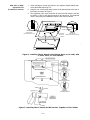
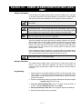
Figure 3. Installing The PC Board And RF Receiver Together In The Cabinet
2 –2
Installing the Control and RF Receiver Circuit Boards Together in the Cabinet
1.
2.
3.
4.
5.
6.
7.
8.
Hang two short (black) mounting clips (provided with receiver) on the
raised cabinet tabs, as shown in Detail B in Figure 3.
Insert the top of the receiver board (removed from its own case as described in its instruc tions) into the slots at the top of the cabinet, as shown
in Detail A in Figure 3. Make sure that the board rests on the correct row of
tabs, as shown.
Swing the base of the board into the mounting clips and secure it to the
cabinet with the accom panying screws (see Detail B in Fig. 3).
Insert the top of the control's board into the slot in the clips and position
two long (red) clips at the lower edge of the board (see Detail C).
Swing this board into place and secure it with two additional screws.
Insert grounding lugs (supplied with the receiver) through the top of the
cabinet into the left-hand terminals of the antenna blocks (at the upper
edge of the receiver board) and secure them to the cabinet top with the
screws provided, as shown in Detail D.
Insert the receiver's antennas through the top of the cabinet, into the
blocks' right-hand terminals, and tighten the screws.
Setup and wiring of the receiver. is contained in the WIRELESS (RF)
ZONE EXPANSION (5700 & 5800 RF SYSTEMS) section.
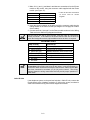
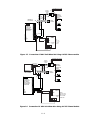
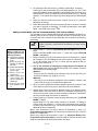
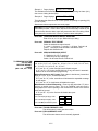
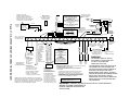
Standard Phone Line Connections
The wiring connections shown here are not applicable if the 4285 Phone
module is used. Refer to the 4285 Phone module section for information
regarding phone line connections, which are different than those shown here.
Incoming
Telco Line
{
{
17
18
19
20
21
➡
INCOMING TELCO LINE
TIP
RING
RED (RING)
GREEN (TIP)
GRAY (RING)
EARTH GROUND
DIRECT
CONNECT
CORD
▲
BROWN (TIP)
▲
TERMINALS
ON CONTROL
➧
▲
▲
Handset
GROUND
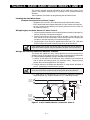
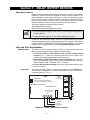
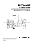
Incoming phone line and handset wiring is connected to the main terminal
block (via a RJ31X jack) as indicated below and shown in Figure 4.
Term. 17: Local Handset (TIP – Brown*).
Term. 18: Local Handset (RING – Gray*).
Term. 19: Incoming Phone Line (TIP – Green*).
Term. 20: Incoming Phone Line (RING – Red*).
* Colors of wires in Direct Connect Cord.
TIP
RJ31X
JACK RING
PREMISES
PHONES
PLUG
Figure 4. Standard Telephone Line Connections
2 –3
Wiring The AC Transformer
No. 1321 Wire the No. 1321 transformer to terminals 1 and 2 on the control board. See
wiring table below for wire gauge to use.
WIRING TABLE
Distance of Transformer
From the Control Panel
Wire Gauge
To Use
Up to 50 feet
# 20
50–100 feet
# 18
100–250 feet
# 16
Wiring to the AC Transformer must not exceed 250 feet using 16 gauge wire.
Do not plug the transformer into the AC outlet until you are instructed to do so
later in the manual.
Installing The Back-Up Battery
Do not attach the connector cable to the battery terminals until you are
instructed to do so later in the manual.
1. Place the 12-volt back-up battery in the control cabinet.
2. Attach Red and Black wires on the battery connector cable to the control
board as follows: †
a. Red to the positive (+) battery tab on the control board (see Summary
of Connections Diagram for location, if necessary).
b. Black to the negative (–) battery tab on the control board.
† These wires may have already been connected to the battery tabs on the control
board. If so, disregard steps a. and b.
DO NOT CONNECT THE WIRES TO THE BATTERY YET!
UL
Use a 4AH battery or larger for UL installations.
Earth Ground Connections
The designated earth ground terminal (21), must be terminated in a good earth
ground for the lightning transient protective devices in this product to be
effective. The following are examples of good earth grounds available at most
installations:
Metal Cold Water Pipe:
Use a non-corrosive metal strap (copper is recommended) firmly secured to
the pipe to which the ground lead is electrically connected and secured.
AC Power Outlet Ground:
Available from 3-prong, 120VAC, power outlets only. To test the integrity of the
ground terminal, use a three-wire circuit tester with neon lamp indicators, such
as the UL-Listed Ideal Model 61–035, or equivalent, available at most electrical
supply stores.
2 –4
Section 3. INSTALLING REMOTE KEYPADS
This section lists the wired keypads that may be used and provides
instructions for wiring and mounting the keypads.
A preliminary check-out procedure is also provided to ensure that the
connected keypads are functioning properly in the system.
Keypads That May Be Used
• Fixed-Word Display: 4127, 4137AD, 6127, 6128, 6137
• Alpha Display: 5137AD, 6138, 6139
• Up to 4 keypads, independent of auxiliary power considerations (you may
need to use an auxiliary power supply if the 500mA aux. output is
exceeded)
If you are going to use a 4285 Phone module, you MUST use addressable
keypads (4137AD, 5137AD, 6128, 6137, 6138, 6139) in the system, but set to
the non-addressable mode (address 31).
Wiring To The Keypads
1. Determine wire gauge by referring to the wiring length/gauge chart below.
For devices (Keypads, RF Receivers, etc.) connected to a single 4-wire
run, determine the current drawn by all units connected to the single wire
run, then refer to the Wiring Run chart to determine the maximum wire
length that can be safely used for each wire size. Current draw for all
devices can be found in the SPECIFICATIONS AND ACCESSORIES
section.
Note: Refer to “Auxiliary Device Current Draw Worksheet” in the FINAL
POWER UP section for current draw for all keypads.
Maximum wire lengths for any device that is homerun to the control can also
be determined from the chart, based on the current draw of that device alone.
Wiring Run Chart For Devices* Drawing Aux Power From The Control (12V+ & 12V–)
TOTAL CURRENT DRAWN BY ALL DEVICES CONNECTED TO A SINGLE WIRE RUN
Wire Size
50mA or less
100mA
300mA
500mA
#22
500 ft (152m)
250 ft (76m)
80 ft (24m)
50 ft (15m)
#20
750 ft (228.6m)
380 ft (116m)
130 ft (39.6m)
80 ft (24m)
#18
1300 ft (396m)
650 ft (198m)
220 ft (67m)
130 ft (39.6m)
#16
1500 ft (457m)
1000 ft (305m)
330 ft (100.5m)
200 ft (70m)
* Includes Keypads, RF Receivers, Relay Units, or 4285 Phone module.
The length of all wire runs must not exceed 1500 feet (457m) when
unshielded quad conductor cable is used (750 feet if shielded cable is used).
This restriction is due to the capacitive effect on the data lines when quad
cable is used.
2.
Run field wiring from the control to the keypads (using standard 4conductor twisted wire cable using the wire gauge determined in step 1).
3.
Connect remote Keypads to terminals 4, 5, 6, and 7 on the control board,
as shown in Figure 5.
3 –1
KEYPAD CONNECTOR CABLE
↓
4
5
6
7
BLACK
RED
GREEN
KEYPADS
YELLOW
CONTROL
TERMINALS
Figure 5. Keypad Connections To The Control Board
Mounting the Keypads
1. Make sure addressable type keypads (4137AD, 5137AD, 6128, 6137,
6138, and 6139) are set to non-addressable mode (address 31), which is
the factory default setting. Refer to the instructions provided with the
keypad for address setting procedure.
2.
Mount the keypads at a height that is convenient for the user. Refer to
the instructions provided with the keypad for mounting procedure.
You can either surface mount or flush mount keypads (using an
appropriate Trim Ring Kit: 5137TRK or 6139TRK). Refer to the mounting
instructions and template included with the keypad and/or trim ring kit for
specific information.
Using a Supplementary Power Supply to Power Additional Keypads
The control provides 500mA for powering keypads (up to a maximum of 4 )
and other devices from the auxiliary power output. The backup battery will
supply power to these keypads in the event that AC power is lost.
When the control’s auxiliary power load for all devices exceeds 500mA, you
can power additional keypads from a regulated, 12VDC power supply (e.g.,
487-12 supplies 12V, 250mA; 488-12 supplies 12V, 500mA). Use a UL Listed,
battery-backed supply for UL installations.
The 487-12/488-12 power supplies have a backup battery which can power
these keypads in the event of AC power loss.
Keypads powered from supplies which do not have a backup battery will not
function when AC power is lost. Therefore, be sure to power at least one
keypad from the Control's auxiliary power output.
Connect the additional keypads as shown in Figure 6, using the keypad wire
colors shown. Be sure to observe the current ratings for the power supply
used.
Make connections directly to the screw terminals as shown in Figure 6. Make
no connection to the keypad blue wire (if present).
Be sure to connect the negative (–) terminal on the Power Supply unit to
terminal 4 (AUX – ) on the control.
3 –2
SUPPLEMENTARY
POWER SUPPLY
CONTROL
TERMINAL STRIP
–
+
TO KEYPAD YEL WIRE
TO KEYPAD GRN WIRE
TO KEYPAD RED WIRE
IMPORTANT:
MAKE THESE
CONNECTIONS
DIRECTLY TO
SCREW TERMINALS
AS SHOWN.
TO KEYPAD BLK WIRE
TO KEYPAD YEL WIRE
TO KEYPAD BLK WIRE
TO KEYPAD GRN WIRE
TO KEYPAD RED WIRE
AUX AUX. DATA DATA
–
+
IN
OUT
4
5
6
7
Figure 6. Using A Supplementary Power Supply For Keypads
Preliminary Check-out Procedure
If you want to check that the system is working before connecting field wiring
from zones and devices, do the following:
1. Temporarily connect a 1000 ohm end-of-line resistor across each of the
basic hard-wire zones 5 and 6, as shown in the Summary of Connections
diagram.
Without actual zone wiring or EOL resistors connected, the keypads in the
system will not display the “Ready” message.
2. Power up the system temporarily by plugging the AC transformer
(previously wired to the control) into a 120VAC outlet.
3. Bus y – S ta ndby (Alpha keypads) or dI (Fixed-word keypads) will be
displayed.
After approximately 1 minute *, the green “READY” LED (or “POWER”
LED on some types of keypads) should light, and the word READY (Fixedword keypads), or DISARMED...READY TO ARM (Alpha keypads) should
be displayed.
* To bypass the 1-minute delay, press # plus 0.
If the “Ready” message is not displayed on any of the keypads in the
system, or a “Not Ready” message is displayed, check the keypad wiring
connections, and make sure each of the 6 basic hard-wired zones has a
1000 ohm resistor connected across its terminals.
4. When you get the proper “Ready” displays on the keypad(s), the system is
functioning properly at this point.
Do not remove the EOL resistors until you are ready to make connections to
the hard-wired zones, to allow for testing later in the manual.
If an OC or OPEN CIRCUIT display is present on the keypad, data from the
control is not reaching the keypad. Check the wiring.
3 –3
3 –4
Section 4. BASIC HARD-WIRED ZONES 5 AND 6
This section provides general information for the hard-wired zones in the
system, plus specific instructions for installing 4-wire smoke/combustion
detectors.
Also included is a procedure for programming the hard-wired zones.
Installing the Hard-Wired Zones
Common Characteristics for Zones 5 and 6
• Response time from 300 –500 milliseconds (400 milliseconds nominal).
• EOLR supervised zones support both open-circuit & closed-circuit devices.
• As many 4-wire smoke detectors as can be powered from Aux Power on
the control (on zone 5).
Wiring Burglary and Panic Devices To Zones 5 and 6
1. Connect sensors/contacts to the hard-wired zone terminals (8 through 16).
See the Summary of Connections diagram .
2. Connect closed circuit devices in series in the high (+) side the loop. The
EOL resistor must be connected in series with the devices, following the
last device. See the Summary of Connections diagram.
3. Connect open circuit devices in parallel across the loop. The 1,000 ohm
EOLR must be connected across the loop wires at the last device.
If the EOLR is not at the end of the loop, the zone will not be properly
supervised, and the system may not respond to an open circuit on the zone.
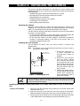
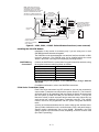
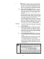
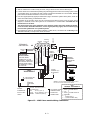
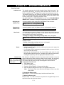
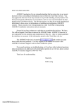
Wiring 4-Wire Smoke/Combustion Detectors on Zone 5
The system will support as many 4-wire detectors as can be powered from
Auxiliary Power on the control on zone 5. Refer to the detector’s instructions
for complete details regarding its proper installation and operation.
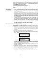
1. Connect 12 volt power for the detectors from Auxiliary Power terminals 4
and 5, (which will interrupt power for fire alarm reset). Observe proper
polarity when connecting detectors. See Figure 7.
2. Connect detectors (including heat detectors, if used) across terminals of
zone 5. All detectors must be wired in parallel.
Remove 1000 ohm EOL resistor if connected across the zone terminals. You
must connect the EOL resistor across the loop wires at the last detector.
3. To meet NFPA 72 requirements, you must use a supervisory module to
supervise power (e.g., System Sensor No. A77-716B Relay module).
+
AUX PWR
OUTPUT
TERMINALS
-
BLK
+
4-WIRE SMOKE
DETECTORS
-
-
•
•
• •
+
-
➔ VIOLET ➔
+
EOL
POWER
SUPERVISION
RELAY
MODULE
A77-716B
•
TO HI SIDE
OF ZONE 5
(TERM 14)
TO LO SIDE
OF ZONE 5
(TERM 15)
•
+
-
HEAT
DETECTOR
HEAT
DETECTOR
Figure 7. 4-wire Smoke Detector Connections (Zone 5).
4 –1
1000
OHMS
EOLR
Compatible System Sensor 4-Wire Smoke/Combustion Detectors
1412
2412
2412TH
A77–716B
2112/24T
4-wire ionization products of combustion detector.
4-wire photoelectric smoke detector.
4-wire photoelectric smoke detector w/135°F (57°C) heat
detector.
EOL relay module (supervisory module for wired 4-wire fire
zone).
Low-profile 4-wire photoelectric smoke detector w/135°F
(57°C) heat detector.
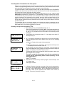
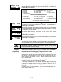
Programming Hard-Wired Zones
1. With at least one 2-line Alpha keypad (5137AD or 6139) connected to the
keypad terminals on the control, power up the system temporarily. If you
had previously connected the AC transformer to the control panel, you
need only plug in the transformer (to 120VAC outlet) to power up the
system.
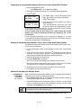
2. Enter the programming mode by keying the following on the Alpha keypad:
INSTALLER code (4 1 1 1) + 8 + 0.
Data fields ✱ 22 RF SYSTEM, and ✱25 OUTPUT RELAY MODULE must be
programmed as required before continuing.
Press ✱ 56. Note that this is an interactive programming mode. You will
use it to program zone numbers, zone types, and alarm report codes for
hard-wired zones (and RF zones).
Note: If you enabled the 5800 wireless system in field ✱22 (a “2” entry),
the first screen prompt will be “Program Tool?... 0 = No 1 = Yes”.
Enter “0” (No). The next prompt will ask you to enter zone number.
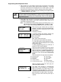
Enter the first zone number that you wish to
Enter Zn Num.
program (or [0][0] to exit zone programming). If
(00 = Quit)
05
you are starting with zone 5, enter and press
[✱] to continue.
Zone Number ↑
If programming another zone, enter the desired
zone number, 06, etc. (zone 02 is shown in the
next display). Press [✱ ] to continue.
Typical summary display
A summary display will appear, showing the
present status of that zone's programming.
Zn ZT – RC
In L
Zn = zone number;
05 03 – 00 HW: –
ZT = zone type;
RC = report code for that zone;
In = input type of zone.
Values displayed are currently programmed
values.
If it is programmed satisfactorily, press [#] to
back up one step and enter the next zone
number, if desired.
If you want to change a zone’s programming,
press [✱ ]. A prompt for Zone Type will appear.
↓ Zone Number
Each zone must be assigned a zone type,
which defines the way in which the system
05 Zone Type
responds to faults in that zone. A detailed
Perimeter
03
explanation of each zone type is provided in
“Response Type Definitions” in the ZONE
↑
Zone Type
RESPONSE TYPE DEFINITIONS section in
the Programming Guide.
Enter the desired zone type code, as listed
next. The example on the left shows zone type
“03”, Perimeter, entered.
3.
4 –2
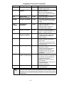
Zone Types
08 = 24 Hr Aux
00 = Zone Not Used
09 = Fire
01 = Entry/Exit #1
10 = Interior w/Delay
02 = Not used
03 = Perimeter
20 = Arm Stay
o 5800
04 = Interior Follower
21 = Arm-Away o RF
05 = Trouble Day/Alarm Night
22 = Disarm
o Systems
06 = 24 Hr Silent
23 = No Alarm
Only
Response
07 = 24 Hr Audible
When the display shows the zone type you
want, press [ ✱] to continue.
You must enter “00” as the zone type for any hard-wired zone that is not
used.
05 Report Code
1st 03 2nd 12
3C
The report code consists of 2 hexadecimal
digits, each in turn consisting of 2 numerical
digits. For example, for a report code of "3C",
enter [0][3] for "3" and [1][2] for "C". Refer to the
SYSTEM COMMUNICATION section f o r
complete information on report codes, if
necessary.
Enter the desired report code and then press [ ✱]
to continue.
Typical summary display
Zn ZT – RC
In L
05 03 – 3C HW: –
Program Alpha?
0 = No 1 = Yes
Enter Zn Num.
(00 = Quit)
0
03
Enter next zone number ↑
Programming
Panic Keys
A summary display will appear, showing the
data for the zone that was just programmed.
If it is programmed satisfactorily, press [✱ ] to
continue.
The next request is to enter Alpha descriptors
for the zones. The entry may be done now
(enter 1), or may be done at a later time using
✱82 interactive mode (enter 0). See the ALPHA
DESCRIPTOR PROGRAMMING section for
specific procedure.
If “0” (no) was entered above, the system will
return to the Enter Zone Number prompt.
Proceed with the programming for the next
zone, i.e., [ ✱] and zone number.
When programming zones, note the following:
The defaults for individual panic keys or panic key pairs are:
Zone 07. ✱ & #, or B: zone type 06 (24-hr silent).
Zone 95. 1 & ✱ , or A: zone type 00 (not used).
Zone 96. 3 & #, or C: zone type 00 (not used).
Panic keys are programmed (or re-programmed) by keying the zone number,
e.g., ✱ 07, ✱95, and ✱ 96, and entering the desired zone type that will provide
the desired panic function for each of these keys, using the list of zone types
below.
06 = 24 Hr Silent
07 = 24 Hr Audible
08 = 24 Hr Aux
09 = Fire
4 –3
When you have programmed all the hard-wired zones and Panic keys
satisfactorily, exit ✱ 56 interactive mode at the Enter Zn Num. prompt by
entering [ 0] [0] as the next zone number.
Then exit the programming mode by keying ✱ 99.
See the special notes below, then proceed to the check-out procedure that
follows.
Special Notes on
Zone
Programming
• In field *56, at the summary line for each zone, the entered values can be
checked. If you wish to change anything, press [#] to move to the previous
entry. Press [#] a number of times to move to earlier entries. Press [✱ ] to
move to later entries again.
• Zone entries can be reviewed by pressing [#][5][6]. Changes cannot be
made here, so this is safer for review. Enter the first zone number to be
viewed and press [#]. To view each zone, press [#] and the zone number
will advance to the next programmed zone. When the end of the list is
reached, press [0][0] to exit. This method of exiting may also be done at any
time during the review.
• To either temporarily or permanently remove a zone from the system, go
into programming mode and press [ ✱][5][6]. Enter the zone number and
press [ ✱]. At the Zone Type prompt, enter [0][0] and [ ✱]. This sets the type
of the zone to Not Used. The next prompt will be "Delete Zone?". "Yes" will
permanently remove the zone from the system while "No" will disable it but
retain all data except the original zone type. You can then go back to this
zone later and put back an active Zone Type to re-enable it.
Check-Out Procedure For Hard-Wired Zones
After installation of all hard-wired devices is completed, the security system
should be checked, as follows.
1. Make certain that all devices and sensors connected to the hard-wired
zones are not in a faulted state. Doors and windows with contacts should
be closed, PIRs should be covered (use a cloth to mask them temporarily if
necessary).
2. Plug in the AC Transformer if you have not already done so..
3. With all hard-wired zones intact, the Alpha keypad connected to the system
should display:
✮✮✮
DI SA RM ED ✮ ✮ ✮
REA DY T O A RM
If the following is displayed,
DI SA RM ED P r e ss ✱
to sh o w fa u lts
press the [ ✱] key to display the faulted zone(s). Restore any faulted zone(s)
as necessary (also make sure that you have connected a 1000 ohm EOL
resistor across the terminals of unused zones).
When the DISARMED ... READY TO ARM message is displayed, you can
proceed to the next step.
4. Fault and then restore every contact or sensor on each zone individually to
ensure that it is being monitored by the system. Each time a zone is faulted,
the keypad should display the number of the faulted zone. When each zone
is restored, the READY TO ARM message should appear again.
5. When you get the proper displays on the keypad(s), the hard-wired zones in
the system are functioning properly.
4 –4
Section 5. WIRED ZONE EXPANSION
This section provides information regarding the use of expansion modules (4219 or 4229) for
expanding the number of wired zones in the system, describes the modules that can be used
and their wiring connections, plus a procedure for programming the wired expansion zones.
Installing Zone Expansion Units
You can add an additional 8 wired expansion EOLR zones to the basic
control's 8 hardwired zones, for a total of 14 wired zones, by using a No. 4219
Wired Expansion Unit, or 4229 Wired Expansion/Relay Unit.
Location
• You can mount an expansion unit within the control
cabinet if space permits. Otherwise, mount the unit
outside the cabinet.
• Units are supervised against removal. Keypads will
display CHECK and zone 09 if a zone expander is
disconnected.
• Units have tamper protection for security when
mounted outside of the cabinet.
• Assign zone numbers 10–17 for the eight wired
expansion loops (designated A to H). You can
program these zones individually (in ✱ 56 interactive
mode, as indicated in “Programming Wired
Expansion Zones” later in this section.
Supervision
Zone Information
Connections
and Set-Up
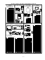
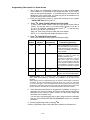
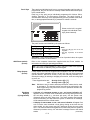
1. Connect the 4219 or 4229 module to the control's keypad terminals (see
diagram below).
2. Set the 4219 or 4229's DIP switch for device address "1" (switch 2
"OFF" and switches 3, 4, 5 "ON"). Switch 1 determines expansion zone A's
response time ("ON" = normal response, "OFF" = fast response). For
location of the DIP switch in the unit, see the diagram below (location of DIP
switch for both units is in the same location).
For additional information, see instructions supplied with the 4219 and
4229.
➞
RELAY
2
➞
EITHER OR BOTH CAN BE USED
RELAY
1
NO C NC
WHT
GRY
VIO
BLK
YEL
ORG
BRN
{
RELAYS
"OFF"
3
4
5
6
TB1
7
9
8
10
11
12
➞
NO
NC
C
GND
NO
NC
C
{
{
RLY
1
2
REED
(TAMPER)
SWITCH
1K
ZONES: A
B
C
D
4
4
3
2
➞
RLY
2
4-PIN CONSOLE PLUG
TAMPER JUMPER POSITION
4229 IN CABINET
(NOT TAMPERED)
4229 REMOTE
(TAMPER PROTECTED)
1
TERMINALS ON
CONTROL PANEL
TB2
➞
}
4229
4229
DIP SWITCH
FOR SETTING ADDRESS
AND ZONE “A” RESPONSE
➞
➞
▲
}
▲
RELAY
CONNECTOR
E
F
G
1
3
2
1
GRN DATA OUT
TO CONTROL
BLK
(–) GROUND
RED
(+) 12V
YEL DATA IN
FROM
CONTROL
TERMINATE EACH
PROGRAMMED ZONE
WITH 1000 OHM (1K)
END-OF-LINE RESISTOR
(EACH ZONE'S MAX.
LOOP RESISTANCE:
300 OHMS + E.O.L.)
H
Figure 8. Wiring Connections, 4219 & 4229 (4229 shown)
5 –1
(TERM 6)
(TERM 4)
(TERM 5)
(TERM 7)
Programming Wired Expansion Zones
1. With at least one 2-line Alpha keypad (6139) connected to the keypad
terminals on the control, power up the system temporarily. If you had
previously connected the AC transformer to the control panel, you need
only plug in the transformer (to 120VAC outlet) to power up the system.
2. Enter the programming mode by keying the following on the Alpha keypad:
Installer code (4 1 1 1) + 8 + 0.
If RF zones, or wired expansion is used, data fields ✱ 22 RF SYSTEM TYPE ,
and ✱ 25 WIRED EXPANSION/RELAY USED must be programmed as
required before continuing (see Programming Form in the separate
Programming Guide.
3.
Press ✱56. Note that this is an interactive programming mode. It is used
to program zone numbers, zone types, and alarm report codes for all
zones that are going to be used.
Note: If you enabled the 5800 wireless system in field ✱ 22 (entry of “2”),
the first screen prompt will be “Program Tool?... 0 = No 1 = Yes”.
Enter “0” (No). The next prompt will ask you to enter zone number.
Enter Zn Num.
(00 = Quit)
10
Zone Number ↑
Zn ZT
RC In L
10 00 – 00 RF: 1
↓ Zone Number
10 Zone Type
Perimeter
03
Zone Type 03 entry shown ↑
Enter the first zone number that you wish to
program (or [0][0] to exit zone programming).
Normally, you will be starting with zone 10 (this
is the default).
Press [✱ ] to continue.
A summary display will appear, showing the
present status of that zone's programming.
Zn = zone number.
ZT = zone type.
RC = report code for that zone.
In = input type of zone (AW for Aux Wired).
L = Loop (not used for wired expansion zones)
Values in the summary display are the currently
programmed values.
To start programming zone 10, press [ ✱ ]. A
prompt for Zone Type will appear.
Each zone must be assigned a zone type, which
defines the way in which the system responds to
faults in that zone. A detailed explanation of
each zone type is provided in “Response Type
Definitions” in the in the separate Programming
Guide.
Enter the desired zone type from the list below.
00 = Zone Not Used
01 = Entry/Exit #1
03 = Perimeter
04 = Interior Follower
05 = Trouble Day/Alarm Night
06 = 24 Hr Silent
07 = 24 Hr Audible
08 = 24 Hr Aux
09 = Fire
10 = Interior w/Delay
23 = No Alarm Response
When the display shows the zone type you
want, press [ ✱] to continue.
10 Report Code
1st 03 2nd 12
3C
5 –2
The report code consists of 2 hexadecimal
digits, each in turn consisting of 2 numerical
digits. For example, for a report code of "3C",
enter [0][3] for "3" and [1][2] for "C". Refer to the
SYSTEM COMMUNICATION section for complete information on report codes, if necessary.
Enter the report code and then press [ ✱ ] to
continue.
At the “INPUT DEVICE” prompt, enter “2” (AUX
Wired) as the input device. The display on the
left will appear.
Press [✱ ] to continue.
10 Input Dev:
LP#
AUX WIRED AW: 01
Typical summary display
Zn ZT
10 03 –
A summary display will appear, showing the
data for the zone that was just programmed.
Note that AW indicates an auxiliary wired (zone
expansion module) zone.
If it is programmed satisfactorily, press [✱ ] to
display the next prompt.
RC In L
03 AW: –
Program Alpha?
0 = No 1 = Yes
Enter Zn Num.
(00 = Quit)
For all zone types, the next request is to enter
Alpha descriptors for the zones. The entry may
be done now (enter 1) or may be done at a later
time using ✱82 interactive menu mode (enter 0).
We recommend that the entry of Alpha
descriptors be done later using ✱82 menu
mode.
See ALPHA DESCRIPTION PROGRAMMING
section for specific procedure.
0
If “0” (No) was entered above, the system will
display a prompt for entry of the next wired
expansion zone number. Proceed with the
programming for the next zone, as indicated
previously.
When all wired expansion zones are
programmed satisfactorily, exit ✱56 mode at the
Enter Zn Num. prompt by pressing: [0] [0] ✱.
11
Enter next zone number ↑
Exit the programming mode by keying ✱99.
Proceed to the check-out procedure that follows.
Check-Out Procedure For Wired Expansion Zones
After you have completed installation of all devices, all wired expansion zones
should be checked as follows:
1. Make certain that all devices and sensors connected to the wired expansion
zones are not in a faulted state. Doors and windows with contacts should be
closed, PIRs should be covered (use a cloth to mask them temporarily if
necessary).
2. With all zones intact (including hard-wired zones), the Alpha keypad
connected to the system should display:
✶✶✶
DI S ARME D ✶ ✶ ✶
RE ADY TO ARM
If the following is displayed,
DI S ARME D P r e s s ✱
to s how fa ul ts
press the [✱ ] key to display the faulted zone(s). Restore any faulted zone(s)
as necessary (also make sure that you have connected a 1000 ohm EOL
resistor across the terminals of unused expansion zones on the 4219 or
4229 module).
When the READY TO ARM message is displayed, you can proceed to the
next step.
(Continued)
5 –3
3. Fault and restore every contact or sensor in each expansion zone
individually to ensure that it is being monitored by the system. Each time a
zone is faulted, the keypad should display the number of the faulted zone
(as programmed by you just previously in ✱56 mode). When each zone is
restored, the READY TO ARM message should appear again.
4. When you get the proper displays on the keypad(s), the wired expansion
zones in the system are functioning properly.
5. Unplug the AC transformer.
If a "CHECK 09" message appears on the display, data from the control is not
being received by the zone expander module. Check your wiring and DIP
switch settings.
5 –4
Section 6. WIRELESS (RF) ZONE EXPANSION
(5700 AND 5800 RF SYSTEMS)
This section provides the following information:
• Wireless systems available.
• Installing the wireless receiver.
• Installing the 5800TM Module.
• Programming for the wireless receiver.
• Setup and installation of the wireless transmitters (5700 or 5800 series).
• Programming the wireless transmitters ( 5700 or 5800 series).
• Checkout procedure for wireless zones (test modes).
UL
Wireless may not be used in UL Commercial Burglary installations.
Wireless Systems Available
The VIA-30PSE supports wireless zones which may be used exclusively, or in
addition to hardwire zones 5 and 6. The system supports two different wireless
systems which have many similarities, but notable differences in the
programming of the transmitters for each system.
The following receivers may be used with this system and each supports the
number of zones shown:
TABLE 1
5700 Series
5800 Series
Receiver
Wireless Zones
Receiver
Wireless Zones
4281L/4281CN-L†
up to 4
up to 8
5881L/5882L†
5881M
4281M/4281CN-M†
up to 8
up to 16
4281H/4281CN-H†
up to 30
5881H/5882H †
up to 30
† 4281 and 5882 type receivers are for use in Canada. See special note below.
In Canada, 5700 systems must use 4281CN series receivers (4281CN-L,
4281CN-M, or 4281CN-H) (with Canadian versions of 5700 type
transmitters). 5800 systems must use 5882 series receivers (5882L or
5882H). Information in this manual relative to the 4281 series of receivers
applies as well to the 4281CN series. Information relative to the 5881 series
of receivers applies as well to the 5882 series. 5881 and 5882 series
receivers can use the same transmitters (5800 type).
Any zone number from 10–63 can be used as a 5700 or 5800 series wireless
zone (do not confuse this with the number of zones that can be used, which is
shown in Table 1 above).
Wireless System Operation and Transmitter Supervision
The receiver responds to status and alarm signals from wireless transmitters
[operating at 345MHz for 5700 series in USA (315MHz in Canada), and 345
MHz for 5800 series (in USA and Canada)] within a nominal range of 200 feet;
the receiver then relays this information to the control.
Except for transmitters that may be carried off-premises (such as the 5700
system's 5701 and 5727, the 5800 system's 5802, 5802CP, 5803, 5804, and
5827, and either system's 5827BD), each transmitter is supervised by a checkin signal that is sent to the receiver at 70–90 minute intervals. If at least one
check-in is not received from each supervised transmitter within a 12-hour
period, the "missing" transmitter number(s) and "CHECK" will be displayed on
the keypad.
6 –1
The supervision for a particular transmitter in the 5800 system may be turned
off by entering it as a "UR" (unsupervised RF) type, as described later.
5800 series transmitters have built-in tamper protection and will cause a
“CHECK” condition to be annunciated if covers are removed.
Each transmitter is also supervised for low battery and will transmit a low
battery signal to its receiver, with the battery having at least 30 days of life remaining. A low battery message and appropriate zone number will appear on
a wired keypad's display.
If a 5727, 5827, or 5827BD wireless keypad has a low battery, it will be
displayed as Zone “00” when it transmits.
Note: After a low or dead battery is replaced, activate the transmitter and
then enter the security code + OFF to clear the system's memory of
the "Low Battery" signal.
Transmitter
Battery Life
• Batteries in the wireless transmitters may last from 4-7 years, depending on
the environment, usage, and the specific wireless device being used.
External factors such as humidity, high or low temperatures, as well as
large swings in temperature may all reduce the actual battery life in a given
installation. The wireless system can identify a true low battery situation,
thus allowing the dealer or user of the system time to arrange a change of
battery and maintain protection for that given point within the system.
• Some transmitters (e.g., 5802, 5802CP, and 5803) contain long-life but nonreplaceable batteries. At the end of their life, the complete unit must be
replaced (and a new serial number entered into the control).
• Button type transmitters (e.g.,. 5802, 5802CP, 5803, 5804) should be
periodically tested by the user for battery life.
Receiver Supervision
The receiver itself is supervised. A tamper report (zone 9) will be generated:
a) If communication with the receiver is interrupted
or
b) If valid RF signals are not received within 12 hours from at least one
supervised wireless transmitter (if any are included in the system)
Wireless System
Installation
Advisories
Disregard the following advisories if the receiver is mounted in the control
cabinet as described in the INSTALLING THE CONTROL section.
1. Place the receiver in a high, centrally located area for best reception. Do
not place receiver on or near metal objects. This will decrease the range
and/or block transmissions. Do not mount receivers or transmitters in an
attic, where extreme temperatures could prevent proper operation.
2. The house IDs must be entered for the receiver (applies only to 5700 RF
system or if using a 5827/5827BD wireless keypad in a 5700 or 5800 RF
system).
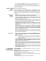
Installation and Setup of the 4281/5881 Wireless Receivers
1. Mount the receiver(s) if not installed previously in the control cabinet, as
indicated in the INSTALLING THE CONTROL section. Receivers can
detect signals from transmitters within a nominal range of 200 feet. Take
this into consideration when determining mounting location outside of the
cabinet.
2. Make sure that the receiver’s DIP switches are set for device address “0”,
as shown in Figure 8 (all switches to the right...OFF).
3.
4.
Connect the receiver's wire harness to the control's keypad terminals (4, 5,
6, and 7). Plug the connector at the other end of the harness into the
receiver (see Figure 9).
Refer to the receiver’s installation instructions for further installation
instructions regarding antenna mounting, etc.
6 –2
ANTENNAS
INSERT IN
RIGHT-HAND
TERMINALS
@@@@@@@@e?@@@@@@@@e?
@@@@@@@@e?@@@@@@@@e?@@@@@@@@
@@@@@@@@
@@
@@h?
@@
@@h?
@@
@@h?
@@
@@h?
@@
@@h?
@@
@@h?
@@
@@
@@
@@
@@
@@
@@
@@
@@
@@
@@
@@
@@
@@
@@
@@
CIRCUIT
BOARD
@@
@@
@@
@@
@@
@@
@@
@@
5882
LOCATION
DIP SWITCH
PLUG
&
SOCKET
}
WIRING
OPENING
KNOCKOUT
AREA FOR
SURFACE
WIRING
{
INTERFERENCE
INDICATOR
LED
@@
@@
@@
@@
@@
@@
@@
@@
?@@
?@@
?@@
?@@
?@@
?@@
?@@@@@@@@
?@@@@@@@@
?@@@@@@@@ ?@@@@@@@@
TO CONTROL’S REMOTE
KEYPAD CONNECTION
POINTS. EACH RECEIVER
MUST BE ON INDIVIDUAL
HOME RUN.
ON
OFF
▲
MOUNTING
HOLES
@@g
@@g
@@g
@@g
@@g
@@g
@@@@@@@@
@@@@@@@@
YELLOW
RED
BLACK
GREEN
▲
NOTE: WHEN CIRCUIT BOARD IS
MOUNTED IN CONTROL’S CABINET,
GROUNDING LUGS (2) PROVIDED
MUST BE INSERTED IN LEFT-HANDTERMINALS OF ANTENNA BLOCKS AND
SECURED TO CABINET (SEE RECEIVER’S AND CONTROLS INSTRUCTIONS)
4
3
2
1
TO RELEASE CIRCUIT
BOARD, REMOVE
SCREWS (2) AND BEND
BACK TABS (S)
Figure 9. 4281, 5881, & 5882 Series Wireless Receivers (cover removed)
Installing the 5800TM Module
Installation of this module is necessary only if you are using one or more
5827BD Wireless Bi-directional keypads.
The 5800TM must be located between one and two feet from the 4281 or 5881
receiver's antennas. The 5800TM must not be installed within the control
cabinet. Mount the unit using its accompanying mounting bracket.
5800TM Wiring
Connections
Connect the 5800TM to the control panel’s keypad connection terminals, using
the supplied connector with flying leads, as follows:
WIRE
RED (+12VDC)
BLACK (Ground)
GREEN (Data to Control)
YELLOW (Data from Control)
BLUE: Not Used
TERMINAL ON CONTROL
Terminal 5
Terminal 4
Terminal 6
Terminal 7
Do not cut any of the jumpers on the 5800TM when using it with the
VIA-30PSE.
For additional information, refer to the 5800TM’s instructions.
5700 Series Transmitter Setup
Each 5700 series transmitter has DIP switches to set both the transmitter's
zone number (Transmitter zone/ID) and the system House ID. The House ID
will be the same for all transmitters and must match the House ID programmed
into the system (in data field ✱ 24) for the wireless receiver. This can be
likened to a family in which everyone has the same last name (House ID), but
each person has a different first name (Transmitter zone/ID). The zone/ID
number must then be programmed into the system using ✱ 56 interactive
mode.
A variety of wireless transmitters can be used to make up the wireless zones.
These include window/door units, smoke detectors, PIRs, and panic buttons.
Zone/ID number assignments can be from 10–63. Remember, the 5700
system supports up to 8 wireless zones, depending on the RF receiver used
(see Table 1 previously).
6 –3
Setting the DIP Switches
on 5700 Series
Transmitters
Set the DIP switches on each 5700 series transmitter to the appropriate
zone/ID number and House ID. Refer to the Compatible 5700 Series
Transmitters table on a following page in this section for zone numbers and
programming information for each particular transmitter. Refer also to DIP
SWITCH TABLES FOR 5700 RF WIRELESS DEVICES later in this section.
The House ID allows the 5700 RF system to identify 5700 transmitters with a
matching House ID. If using a 5700 RF wireless system, the DIP switches on
the transmitters must match the system House ID programmed into the
control (in data field ✱ 24). If using a 5827BD wireless keypad, the House ID
also applies. Other than the 5827 and 5827BD, 5800 series devices do not
communicate by House ID, but by transmitting a unique serial number to the
control. In this case, programming a House ID is not necessary.
Wireless Zone/ID
Assignments for 5700
Series Transmitters
Each wireless zone can be assigned any zone response type, such as
Entry/Exit, Interior Follower, Perimeter, etc. (see the ZONE RESPONSE TYPE
DEFINITIONS section in the separate Programming Guide for a detailed
explanations of each zone type). For 5700 series transmitters, each response
type uses a certain range of zone numbers. Each range of zone/ID numbers is
shown below.
Zone Type
Transmitter Zone/ID #
Entry/Exit Burg ....................... 10 through 47 *
Perimeter Burg....................... 10 through 47 *
Interior Burg ........................... 10 through 47 *
32 through 47 * (5775)
Fire......................................... 48 through 63 *
48 through 55 ** (5706)
24 Hour Panic ........................ 48 through 63 *
(silent or audible) ................... 62 or 63 *** (5701)
Day/Night Burglary ................. 10 through 47 *
24 Hour Auxiliary.................... 10 through 47 *
–––––––––––––––––––––––––––
–––––––––––––––––––––––––––––––––––––––––––––––––––––––––
* Zone/ID numbers 10–63 can be used, but you should note the following in
connection with certain transmitter zone/IDs identified as follows:
** Transmitter IDs 48 through 55 have highest signal priority.
*** Transmitter IDs 62 and 63 are unsupervised to allow removal of the 5701 off
premises — signal priority is lower than that of fire, but higher than burglary.
Notes:
1.
2.
3.
Transmitters set for zone/IDs 48–55 (FIRE) will transmit once every 12
seconds while the zone is faulted. Transmitters set for zone/IDs 56–63 will
transmit once every 3 seconds while faulted. These two ranges of zone/ID
numbers have high signal priority and their frequent transmissions while
faulted ensure re-triggering of the alarm until the cause is removed. Bear
in mind that because of this, transmitter battery life could be shortened.
Transmitters set for an zone/IDs of 32 through 47 will have a 3-minute
lock-out between transmissions. Use this range of zone/ID numbers for
sensors protecting frequently used doors or windows to conserve battery
life.
Refer also to “Compatible 5700 Series Transmitters” on a following page.
6 –4
DIP SWITCH TABLES FOR 5700 RF SYSTEM WIRELESS DEVICES
HOUSE ID
SWITCH SETTING FOR ALL
DEVICES EXCEPT 5716
2
3
4
5
UP
UP
UP
UP
UP
UP
UP
UP
UP
UP
UP
UP
UP
UP
UP
—
—
—
—
—
—
—
—
—
—
—
—
—
—
—
—
UP
UP
UP
UP
UP
UP
UP
—
—
—
—
—
—
—
—
UP
UP
UP
UP
UP
UP
UP
UP
—
—
—
—
—
—
—
—
UP
UP
UP
—
—
—
—
UP
UP
UP
UP
—
—
—
—
UP
UP
UP
UP
—
—
—
—
UP
UP
UP
UP
—
—
—
—
UP
—
—
UP
UP
—
—
UP
UP
—
—
UP
UP
—
—
UP
UP
—
—
UP
UP
—
—
UP
UP
—
—
UP
UP
—
—
—
UP
—
UP
—
UP
—
UP
—
UP
—
UP
—
UP
—
UP
—
UP
—
UP
—
UP
—
UP
—
UP
—
UP
—
UP
—
16
8
4
2
1
SIDE
VIEW (UP)
DIP
UP
HOUSE ID (1 SHOWN)
SIDE
VIEW (UP)
DN
1 2 3 4 5 6
HOUSE ID (1 SHOWN)
5727 KEYPAD
1 2 3 4 5 6
SIDE
VIEW (UP)
7 8
}
DIP
XMTR
ID
DN
32
33
34
35
36
37
38
39
40
41
42
43
44
45
46
47
XMTR ID
(48 SHOWN)
HOUSE ID (1 SHOWN)
1 2 3 4 5
UP
5711/5711WM
DOOR/WINDOW TRANSMITTER
6
UP
UP
UP
UP
—
—
—
—
48
49
50
51
52
53
54
55
SIDE
VIEW
(DN)
DN
DIP SWITCH POSITION
XMTR
ID
XMTR ID
FIXED AT
“00”
IMPORTANT
SET SWITCHES WITH
BATTERY REMOVED
7
UP
UP
—
—
UP
UP
—
—
8
UP
—
UP
—
UP
—
UP
—
TERMINALS
SW4
DIP
SW3
6 5 4 3 2 1
UP
DIP
SW4
SIDE
VIEW (UP)
HOUSE ID (1 SHOWN)
1 2 3 4 5 6
SIDE
VIEW
(DN)
7 8 9 10 11 12
XMTR ID (33 SHOWN)
HOUSE ID (1 SHOWN)
UP
}
}
XMTR ID
POS.1: UP = NORMAL RESPONSE
(33 SHOWN)
DN = FAST RESPONSE
POS. 2: UP = NO COVER TAMPER
DN = COVER TAMPER (use N.C. setting)
XMTR
ID
1
2
3
4
5
6
7
8
9
10
11
12
13
14
15
16
17
18
19
20
21
22
23
24
25
26
27
28
29
30
31
32
BIT
VALUE:
6 5 4 3 2 1
DN
UP
UP
SW3
POS.12: UP = N.O.
— = N.C
(Avoid ID 32-37 with N.O.)
DN
POS. 6: UP = N.O.
DN = N.C.
DIP SWITCH POSITION
6
UP
UP
UP
UP
UP
UP
UP
UP
UP
UP
UP
UP
UP
UP
UP
UP
UP
UP
UP
UP
UP
UP
UP
UP
UP
UP
UP
UP
UP
UP
UP
—
7
UP
UP
UP
UP
UP
UP
UP
UP
UP
UP
UP
UP
UP
UP
UP
—
—
—
—
—
—
—
—
—
—
—
—
—
—
—
—
UP
8
UP
UP
UP
UP
UP
UP
UP
—
—
—
—
—
—
—
—
UP
UP
UP
UP
UP
UP
UP
UP
—
—
—
—
—
—
—
—
UP
9
UP
UP
UP
—
—
—
—
UP
UP
UP
UP
—
—
—
—
UP
UP
UP
UP
—
—
—
—
UP
UP
UP
UP
—
—
—
—
UP
10
UP
—
—
UP
UP
—
—
UP
UP
—
—
UP
UP
—
—
UP
UP
—
—
UP
UP
—
—
UP
UP
—
—
UP
UP
—
—
UP
11
—
UP
—
UP
—
UP
—
UP
—
UP
—
UP
—
UP
—
UP
—
UP
—
UP
—
UP
—
UP
—
UP
—
UP
—
UP
—
UP
32
16
8
4
2
1
XMTR
ID
33
34
35
36
37
38
39
40
41
42
43
44
45
46
47
48
49
50
51
52
53
54
55
56
57
58
59
60
61
62
63
BIT
VALUE
HOUSE
ID
DIP SWITCH POSITION
6
—
—
—
—
—
—
—
—
—
—
—
—
—
—
—
—
—
—
—
—
—
—
—
—
—
—
—
—
—
—
—
7
UP
UP
UP
UP
UP
UP
UP
UP
UP
UP
UP
UP
UP
UP
UP
—
—
—
—
—
—
—
—
—
—
—
—
—
—
—
—
8
UP
UP
UP
UP
UP
UP
UP
—
—
—
—
—
—
—
—
UP
U
UP
UP
UP
UP
UP
UP
—
—
—
—
—
—
—
—
9
UP
UP
UP
—
—
—
—
UP
UP
UP
UP
—
—
—
—
UP
UP
UP
UP
—
—
—
—
UP
UP
UP
UP
—
—
—
—
10
UP
—
—
UP
UP
—
—
UP
UP
—
—
UP
UP
—
—
UP
UP
—
—
UP
UP
—
—
UP
UP
—
—
UP
UP
—
—
11
—
UP
—
UP
—
UP
—
UP
—
UP
—
UP
—
UP
—
UP
—
UP
—
UP
—
UP
—
UP
—
UP
—
UP
—
UP
—
32
16
8
4
2
1
1
2
3
4
5
6
7
8
9
10
11
12
13
14
15
16
17
18
19
20
21
22
23
24
25
26
27
28
29
30
31
BIT
VALUE:
DN
UP = PULSE COUNT
— = INST. MODE
DIP SWITCH POSITION
6
UP
UP
UP
UP
UP
UP
UP
UP
—
—
—
—
—
—
—
—
7
UP
UP
UP
UP
—
—
—
—
UP
UP
UP
UP
—
—
—
—
8
UP
UP
—
—
UP
UP
—
—
UP
UP
—
—
UP
UP
—
—
9
UP
—
UP
—
UP
—
UP
—
UP
—
UP
—
UP
—
UP
—
5716 DOOR/WINDOW TRANSMITTER
DIP
2
XMTR ID
(32 SHOWN)
UP
TERMINAL
BLOCK
1
7 8 9 10
UP
POS.6 UP= XMTR ID 62
DN= XMTR ID 63
DIP
DIP
MIRROR
DIP
DIP
1 2 3 4 5 6
5715
UNIVERSAL TRANSMITTER
5775 PIR
DETECTOR/TRANSMITTER
}
1
1
2
3
4
5
6
7
8
9
10
11
12
13
14
15
16
17
18
19
20
21
22
23
24
25
26
27
28
29
30
31
5706/5707 SMOKE
DETECTORTRANSMITTER
HOUSE ID (1 SHOWN)
DIP SWITCH POSITION
DEVICE
ID
BIT
VALUE:
5701 PANIC TRANSMITTER
DIP SWITCH POSITION
5
—
UP
—
UP
—
UP
—
UP
—
UP
—
UP
—
UP
—
UP
—
UP
—
UP
—
UP
—
UP
——
UP
—
UP
—
UP
—
4
UP
—
—
UP
UP
—
—
UP
UP
—
—
UP
UP
—
—
UP
UP
—
—
UP
UP
—
—
UP
UP
—
—
UP
UP
—
—
3
UP
UP
UP
—
—
—
—
UP
UP
UP
UP
—
—
—
—
UP
UP
UP
UP
—
—
—
—
UP
UP
UP
UP
—
—
—
—
2
UP
UP
UP
UP
UP
UP
UP
—
—
—
—
—
—
—
—
UP
UP
UP
UP
UP
UP
UP
UP
—
—
—
—
—
—
—
—
1
UP
UP
UP
UP
UP
UP
UP
UP
UP
UP
UP
UP
UP
UP
UP
—
—
—
—
—
—
—
—
—
—
—
—
—
—
—
—
1
2
4
8
16
TRANSMITTER
ID
1
2
3
4
5
6
7
8
9
10
11
12
13
14
15
16
17
18
19
20
21
22
23
24
25
26
27
28
29
30
31
32
33
34
35
36
37
38
39
40
41
42
43
44
45
46
47
48
49
50
51
52
53
54
55
56
57
58
59
60
61
62
63
BIT
VALUE:
DIP SWITCH POSITION
6
—
UP
—
UP
—
UP
—
UP
—
UP
—
UP
—
UP
—
UP
—
UP
—
UP
—
UP
—
UP
—
UP
—
UP
—
UP
—
UP
—
UP
—
UP
—
UP
—
UP
—
UP
—
UP
—
UP
—
UP
—
UP
—
UP
—
UP
—
UP
—
UP
—
UP
—
UP
—
5
UP
—
—
UP
UP
—
—
UP
UP
—
—
UP
UP
—
—
UP
UP
—
—
UP
UP
—
—
UP
UP
—
—
UP
UP
—
—
UP
UP
—
—
UP
UP
—
—
UP
UP
—
—
UP
UP
—
—
UP
UP
—
—
UP
UP
—
—
UP
UP
—
—
UP
UP
—
—
4
UP
UP
UP
—
—
—
—
UP
UP
UP
UP
—
—
—
—
UP
UP
UP
UP
—
—
—
—
UP
UP
UP
UP
—
—
—
—
UP
UP
UP
UP
—
—
—
—
UP
UP
UP
UP
—
—
—
—
UP
UP
UP
UP
—
—
—
—
UP
UP
UP
UP
—
—
—
—
3
UP
UP
UP
UP
UP
UP
UP
—
—
—
—
—
—
—
—
UP
UP
UP
UP
UP
UP
UP
UP
—
—
—
—
—
—
—
—
UP
UP
UP
UP
UP
UP
UP
UP
—
—
—
—
—
—
—
—
UP
UP
UP
UP
UP
UP
UP
UP
—
—
—
—
—
—
—
—
2
UP
UP
UP
UP
UP
UP
UP
UP
UP
UP
UP
UP
UP
UP
UP
—
—
—
—
—
—
—
—
—
—
—
—
—
—
—
—
UP
UP
UP
UP
UP
UP
UP
UP
UP
UP
UP
UP
UP
UP
UP
UP
—
—
—
—
—
—
—
—
—
—
—
—
—
—
—
—
1
UP
UP
UP
UP
UP
UP
UP
UP
UP
UP
UP
UP
UP
UP
UP
UP
UP
UP
UP
UP
UP
UP
UP
UP
UP
UP
UP
UP
UP
UP
UP
—
—
—
—
—
—
—
—
—
—
—
—
—
—
—
—
—
—
—
—
—
—
—
—
—
—
—
—
—
—
—
—
1
2
4
8
16
32
For 5700 series transmitters not shown in this table, refer to the instructions accompanying each transmitter.
6 –5
Compatible 5700 Series Transmitters
Model
5701
Product
Panic Transmitter
5706
Photoelectric Smoke
Detector
48–55
5711
10–63
5715WH
Slimline Door/
Window Transmitter
Universal Transmitter
5716
5716WM
Door/Window
Transmitter
10–63
5742
Audio Discriminator
10–63
5743
Dual Technology
Glassbreak Detector
10–63
5775
PIR Detector
32–47
5727
Wireless Keypad
5827BD
5799
UL
Zone/ID #
62 or 63
10–63
House ID
Wireless Keypad
House ID
(usable in a 5700 System)
Magnets
Description
• Programmable for either silent or
audible 24-hour alarm.
• One-piece smoke detector with
built-in transmitter.
• Built-in UL Listed 85dB piezo
electric alarm sounder and audible
low battery warning.
• Can be used with any closed or
open circuit sensor.
• DIP switch selectable for fast response, and open or closed sensor
usage.
• Has a tamper protected cover.
• Can be used with any open or
closed circuit sensor.
• Features a built-in reed switch.
• 5716WM includes magnet.
• For use in unoccupied areas to
detect the sound of shattering glass
when a window is broken.
• Detects the sound and shock of
breaking glass and requires the
presence of both to initiate an
alarm condition.
• Dual element passive infrared
detector with built-in selectable
pulse count.
Note: There is a 3-minute lock-out
between fault transmissions to con
serve battery life.
• Can be used to turn the burglary
protection on and off.
• Features the same built-in panic
functions as wired keypads.
• Identified as zone "00" (on wired
keypads) when it transmits with a
low battery.
• Requires use of 5800TM Module.
• RF House ID must be programmed
in field ✱24, and the wireless keypad set to the same ID.
• Operates the system similarly to
wired keypads
• Can indicate system status via its 3
LEDs and sounder.
• Includes 3 panic keys.
• Package of 8 magnets for use with
5716 transmitters
The 5711, 5715, and 5716 do not supervise their loop wiring for shorts.
Therefore, for UL Household Burglary installations, the loop wiring may not
exceed 3 feet.
6 –6
Programming the Control For a 5700 Wireless System
1. With at least one two-line Alpha keypad wired and set to address 31
(default), power up the system temporarily by plugging the AC transformer
(previously wired to the control) into a 120VAC outlet.
2. Enter data field programming mode: Installer Code + 8 + 0.
3 Set data field ✱ 22 (RF SYSTEM TYPE) to “1” (5700)
4. Enter the House ID (01–31) in data field ✱ 24. (RF HOUSE ID CODE)
The House ID entered in this field will identify 5700 series transmitters in a
5700 RF system (all 5700 type transmitters are set for the same House ID).
If a 5827BD wireless keypad is to be used in a 5700 RF system, the same
House ID code entered in this field must also set on the 5827BD wireless
keypad(s).
5. Exit the programing mode by keying ✱ 99.
The DIP switches in each 5700 series transmitter that is going to be used in the
system must be set to the appropriate zone/ID number and House ID. Refer to
“Setting the DIP Switches On 5700 Series Transmitters” and “Wireless Zone/ID
Assignments for 5700 Series Transmitters” on a previous page, if necessary.
The system House ID must have been programmed in data field ✱ 24, and the
DIP switches on all transmitters set for the same ID. If using a 5827BD wireless
keypad, the House ID also applies.
Note: The 5827BD is keypad programmable; the 5727 wireless keypad is
programmed via its DIP switches. Refer to the instructions supplied
with the 5827BD and 5727 for details.
Batteries should be installed in all transmitters.
Using the House ID Sniffer Mode (5700 Systems)
4281 series RF receivers respond only to 5700 transmitters (and 5827BD
wireless keypads) set to the same House ID (01–31) programmed into the
control panel. This prevents system interference from transmitters in other
nearby systems. Using the House ID Sniffer Mode will make sure you have not
chosen a House ID that is in use in a nearby system.
1. Enter your Installer Code + # + 2 .
2. The receiver will now "sniff" out any House IDs in the area and display
them. Keep the receiver in this mode for about 2 hours to give a good
indication of the House IDs being used. Be sure you have used a House
ID that is not displayed .
3. To exit the Sniffer Mode, simply enter your Installer Code + OFF.
Since the Sniffer Mode effectively disables wireless point reception, Sniffer
Mode cannot be entered while the system is armed.
Do not permanently mount the transmitters yet; a Go/No Go test (described
later) must be performed after programming is completed to make sure
reception of each transmitter's signal at the proposed mounting location is
adequate.
Zone Programming For 5700 Transmitters
Before proceeding, each of the 5700 transmitters in the system should have
been assigned a unique Zone/ID number via its DIP switches, and this
information marked on the back of the transmitter. “Wireless Zone/ID
Assignments for 5700 Series Transmitters” on a previous page provides
information concerning the assignment of Zone/ID numbers to transmitters.
1. With a 2-line Alpha keypad connected to the keypad terminals, power up
the system temporarily. If you had previously connected the AC transformer
to the control panel, you need only plug the transformer in (to 120VAC
outlet) to power up the system.
2. Enter the programming mode by keying: Installer Code + 8 + 0.
6 –7
Data field ✱22 RF SYSTEM TYPE, must have been programmed for a 5700
RF system (“1”). Also, the House ID should have been entered in field ✱24,
and all 5700 transmitters set to the same House ID.
4. Press ✱ 56. (Zone Programming Mode)
Use this mode to program zone numbers, zone types, and alarm report
codes for all 5700 wireless zones that are going to be used in the system.
5700 transmitters are programmed into the system one at a time, starting
with the lowest Zone/ID number that has been assigned to it previously via
its DIP switches.
Example: If the first transmitter to be programmed has been set via its DIP
switches to Zone/ID 20, you will program zone types, and alarm report
codes for that transmitter in zone 20.
5. Enter the zone number that you wish to
program. As an example, zone 20 is shown
entered here.
Zone numbers between 10 and 63 can be
assigned to transmitters. However, the total
number of wireless zones that can be used is 8
for 5700 RF systems (see Table 1 on a
previous page).
En te r Zn Nu m .
( 0 0 = Q u it)
20
Zone 20 entered ↑
Zn ZT – RC I n : L
20 00 – – – : –
6.
A summary display will appear, showing the
status of that zone's program.
If it is programmed satisfactorily, press [#] to
back up one step and enter another zone
number, if desired.
If the zone is not programmed, or you want to
change it, press [✱ ]. A prompt for Zone Type
will appear.
↓ Zone Number
2 0 Zo n e T ype
P e r im e te r
03
Entry for Zone Type
03 shown
A detailed explanation of
each zone type is provided
in the ZONE RESPONSE
TYPE DEFINITIONS
section in the separate
Programming Guide.
7. Each zone must be assigned a zone type,
which defines the way in which the system
responds to faults in that zone.
Enter the zone type (or change it, if necessary).
Zone types that you can assign are listed below.
Enter the desired zone type code as listed.
00 = Zone Not Used
01 = Entry/Exit Burglary
03 = Perimeter
04 = Interior Follower
05 = Trouble Day/Alarm Night
06 = 24 Hr Silent
07 = 24 Hr Audible
08 = 24 Hr Aux
09 = Fire
10 = Interior w/Delay
23 = No Alarm Response
(e.g., relay activation)
When the display shows the zone type you
want, press [ ✱] to continue.
2 0 Re po r t Co de
1 st 0 3 2 n d 1 2 3 C
8. Enter the report code.
The report code consists of 2 hexadecimal
digits, each in turn consisting of 2 numerical
digits. For example, for a report code of "3C",
enter [0][3] for "3" and [1][2] for "C".
See the SYSTEM COMMUNICATIONS section
for complete information on report codes, if
necessary.
Press [✱ ] to continue.
9. For the hardwired zones (HW), and the zones
for a 5700 system's transmitters (RF), the Input
Device types are automatically assigned (Panic,
Duress, and Tamper inputs are not applicable).
2 0 I n pu t De vic e
RF T r a n s.
RF :
6 –8
10. Mark the zone number on the transmitter.
11. After the transmitter has been entered into the
system, press [✱ ] to continue.
Typical summary display
Zn ZT – RC In: L
20 03 – 3C RF: –
P r o g r a m A lph a ?
0 = No 1 = Ye s 0
En te r Zn Nu m .
( 0 0 = Q u it)
21
A summary of the programmed values for the
selected zone will now be displayed
If all is okay, press [ ✱] for the next display.
Alpha descriptors for the zones can be done
now, or may be done at a later time using ✱ 82
interactive mode (enter “0”).
Refer to ALPHA DESCRIPTOR PROGRAMMING
section for performing this procedure in the ✱ 82
interactive menu mode.
If “0” (no) was entered in response to the
P r o g r a m A lph a ? question, a prompt will
then be displayed for entry of the number for the
next wireless zone to be programmed.
12. Proceed with the programming of the next
wireless zone, starting at step 5 again.
13. To exit field ✱ 56 when completed, key [0 ][0] at
the “Enter Zone Number” prompt.
14.Exit the programming mode by keying
Special Notes on Zone
Programming (5700 RF
Systems)
Go/No Go Test
✱99.
• In field *56, at the summary line for each zone, the entered values can be
checked. If you wish to change anything, press [#] to move to the previous
entry. Press [#] a number of times to move to earlier entries. Press [✱ ] to
move to later entries again.
• Zone entries can be reviewed by pressing [#][5][6]. Changes cannot be
made here, so this is safer for review. Enter the first zone number to be
viewed and press [#]. To view each zone, press [#] and the zone number
will advance to the next programmed zone. When the end of the list is
reached, press [0][0] to exit. This method of exiting may also be done at any
time during the review.
• To either temporarily or permanently remove a zone from the system, go
into programming mode and press [ ✱][5][6]. Enter the zone number and
press [ ✱]. At the Zone Type prompt, enter [0][0] and [ ✱]. This sets the type
of the zone to Not Used. The next prompt will be "Delete Zone?". "Yes" will
permanently remove the zone from the system, while "No" will disable it but
retain all data except the original zone type. You can then go back to this
zone later and put back an active Zone Type to re-enable it.
Before mounting transmitters permanently, conduct Go/No Go tests to verify
adequate signal strength and reorient or relocate transmitters if necessary.
During this mode, wireless receiver gain is reduced by 50%. Testing in this
mode assists in determining good mounting locations for the transmitters and
verifies that the RF transmission has sufficient signal amplitude margin for the
installed system.
1. Enter the Installer Code + # + 4
2. Once transmitters are placed in their desired locations and the approximate
length of wire to be run to sensors is connected to the transmitter's screw
terminals, fault each transmitter. Do not conduct this test with your hand
wrapped around the transmitter as this will cause inaccurate results.
• The keypad will beep three times to indicate signal reception.
• If the keypad does not beep, re-orient or move the transmitter to another
location. Usually a few inches in either direction is all that is required.
6 –9
3. Mount the transmitter according to the instructions provided with the
transmitter.
4. Exit the GO/NO GO test mode by entering Installer Code + (OFF).
You should now proceed to “Check-Out Procedure for Wireless Zones” at
the end of this section.
5800 Series Transmitter Setup
General
5800 series transmitters have built-in serial numbers that must be enrolled in
Information
the system using the ✱ 56 or ✱ 83 interactive mode, or input to the control via
the downloader. 5800 series transmitters (except 5827 described separately)
do not have DIP switches.
5800 Series
Transmitter Input
Loops
UL
Each transmitter's zone number is programmed into the system in ✱56 mode.
Some transmitters, such as the 5816 and 5817, can support more than one
"zone" (referred to as loops or inputs). On the 5816 for example, the wire connection terminal block is loop 1, the reed contact is loop 2. Each loop must be
assigned a different zone number and entered separately.
For button transmitters (wireless "keys"), such as the 5804, you must assign a
unique zone number to each individual button used on the transmitter. Each
button on the transmitter also has a pre-designated loop or input number,
which is displayed when entered.
Refer to 5800 Series Transmitter Input Loop Identification in the separate
Programming Guide manual
The 5816, and 5817 do not supervise their loop wiring for shorts Therefore,
for UL Household Burglary installations, the loop wiring may not exceed 3 ft.
Programming an RF House ID (01–31) in field ✱ 24 is necessary only if
using 5827 or 5827BD wireless keypads. An RF House ID is not necessary
for other 5800 series transmitters and the entry should be left at “00” (default)
in those cases.
The 5827 wireless keypad reports low battery status as zone "00."
5800 Series
Transmitter Input
Types
All of the transmitters described have one or more unique factory assigned
loop inputs. Each of the inputs requires its own programming zone (e.g., a
5803's three button inputs require three programming zones).
5800 Transmitters can be entered into the system as one of the following input
device types:
Input Device Type
Description
"RF"
(Supervised RF)
Sends periodic check-in signals, as well as fault,
restore, and low battery signals. The transmitter
must remain within the receiver's range.
"UR"
(Unsupervised RF)
Sends all the signals that the "RF" type does,
but the control does not supervise the check-in
signals. The transmitter may therefore be
carried off-premises.
"BR"
(Unsupervised Button
RF)
These send only fault signals. They do not send
low battery signals until they are activated. The
transmitter may be carried off-premises.
Do not install batteries in wireless transmitters until ready to use, as will be
indicated under Programming the RF Transmitters (5800 RF Systems later
in this section. Though it is not critical to remove batteries after entering into
the system, it is recommended in order to avoid interference while entering
additional transmitters into the system.
6 –10
Compatible 5800 Series Transmitters
Enter As Input
Device Type
Description
Model
Product
5801
Wireless Panic
Transmitter
UR or RF
5802
Pendant
(Personal Emergency
Transmitter)
BR Only
• Has four pushbuttons, each with a
unique input (loop) code.
• Programmable responses (e.g.,
Panic, Arm–Stay, Arm–Away,
Disarm, etc.
• Has single pushbutton.
• Usually programmed for response
type of 24-Hr Audible or 24-Hr Silent
(other zone responses are possible).
• Contains a non-replaceable battery.
At the end of the battery's life, the
entire unit must be replaced.
5802CP
Belt Clip
(Personal Emergency)
BR Only
Same as 5802.
5802MN
Miniature
(Personal Emergency
Transmitter)
UR or RF
• Has single pushbutton.
• Usually programmed for a response
type of 24-Hr. Audible or 24-Hr.
Silent (other zone responses are
possible).
5804
Wireless Key
Transmitter
BR Only
5806
5807
Wireless Photoelectric
Smoke Detectors
RF
• Has four pushbuttons, each with a
unique input (loop) code.
• Programmable responses (e.g.,
Arm–Stay, Arm–Away, Disarm, etc.).
• One-piece smoke detectors with a
built in transmitter.
5808
Wireless Photoelectric
Smoke Detector
RF
• One-piece smoke detectors with a
built in transmitter.
• Has built-in thermal circuitry to
detect temperatures above 135°F,
and tamper switch on base.
5816
Door/Window
Transmitter:
RF
• Has two unique input (loop) codes:
one for a wired closed circuit
contact loop; the other for a built-in
reed switch (used in conjunction
with a magnet).
5816
TEMP
Low Temperature
Sensor
RF
• Transmits a fault condition when
temperature drops below 45 °F.
5817
Multi-Point
Universal Transmitter
RF
• Has three unique input (loop)
codes: one for a "Primary" contact
loop with programmable options;
the others for two "Auxiliary" closed
circuit contact loops.
UL
The 5816 and 5817 do not supervise their loop wiring for shorts. Therefore, for
UL Household Burglary installations, the loop wiring may not exceed 3 feet.
(Continued)
6 –11
Compatible 5800 Series Transmitters (Continued)
Enter As Input
Device Type
Description
Model
Product
5819
Shock Processor
Transmitter
RF
• Connects to externally mounted
inertia-type shock detector (not
supplied).
• Has built-in tampered cover switch.
• Has 3 unique input (loop) codes:
Loop 1: Terminals for a wired, N.C.
sensor loop.
Loop 2: For a closed circuit contact
loop using the built-in reed switch in
conjunction with a magnet.
Loop 3: Terminals for a wired,
closed circuit contact loop.
5827
Wireless Keypad
House ID
• Can be used to turn the burglary
protection on and off.
• Features the same built-in panic
functions as wired keypads.
• The keypad is identified as zone
"00" on wired keypads when it
transmits with a low battery.
5827BD
Wireless Two-Way
Keypad
(used with 5800TM)
House ID
5850
(GBD)
Glass Break Detector
RF
• Operates the system similarly to
wired keypads.
• Can indicate system status via its 3
LEDs and sounder.
• Includes 3 panic keys.
• House ID must be set.
• Requires 5800TM Transmitter
Module.
• Requires both sound and shock of
breaking glass to cause alarm to be
transmitted.
5890
PIR Detector
RF
5899
Magnets
• Dual element passive infrared
detector/transmitter with selectable
pulse count.
Note : There is a 3-minute lock-out
between fault transmissions to
conserve battery life.
Package of 4 magnets for use with
5816 and 5817 transmitters.
Programming the RF Transmitters (5800 RF Systems)
1. With at least one 2-line Alpha keypad connected to the keypad terminals,
power up the system temporarily. If you had previously connected the AC
transformer to the control panel, you need only plug the transformer in (to
120VAC outlet) to power up the system.
2. Enter the programming mode by keying: Installer Code + 8 + 0.
Data field ✱22 RF SYSTEM TYPE, must have been programmed for a 5800
RF system before continuing (“2” entered in that field).
3.
✱24.
RF HOUSE ID CODE
The House ID identifies a 5827 or 5827BD Wireless keypad if it is used
(enter 01–31). The wireless keypads should be set to the same ID. If no
wireless keypad is to be used, leave as “00”.
6 –12
Enrolling 5800 Transmitters Into The System
There are two methods that may be used to enroll transmitters. The first method is performed
in ✱56 zone programming mode (which is contained in this section) and describes how to enroll
each transmitter into the system as you are entering the zone information.
The second method is called "sequential mode" and uses ✱ 83 (described in the SEQUENTIAL
MODE section later in this manual. This section describes how to enroll all the transmitters into
the system after all zone information has been entered.
As an option, the zone programming and sequential modes allow you to use a 5803 or 5804
button-type transmitter as a "program tool." The advantage of using a program tool is that it
tells the control that you are about to enroll a transmitter into the system. You can move to the
physical location of the transmitter to be enrolled, press the upper left-hand button of the
program tool, and then trip the intended transmitter (see step 10 for operation). This helps to
prevent random signals from being accepted into the system until you are ready to enroll the
intended transmitter.
The transmitter that you use as the program tool can also be used as a transmitter in the
system. If you plan to use an existing transmitter, it must first be enrolled into the system as its
associated zones. You may then program it as the tool.
Enrolling Through Zone Programming (✱ 56)
1. Enter Programming mode [Installer Code] + 8 + 0.
Enter Zone Programming by pressing ✱56. If the system has been set
up to use 5800 series RF, and a program tool has been entered, skip
to step 4. If no program tool has been entered, the following prompt
will appear:
2.
If a program tool is being used, enter "1." If not using a tool, enter "0"
Program Tool?
and skip to Step 4.
0 = No, 1 = Yes 0
00 Input S/N:
L
A X X X–X X X X
00 Input S/N:
A123-4567
3.
If "1" is entered, the system will prompt for the unit’s serial number.
Enter the program tool’s serial number using one of the following
methods:
a) Enter the 7-digit serial number for the transmitter
or
b) Press any button on the transmitter. The keypad should beep twice
and display the serial number of the tool.
In this example, the serial number is A123-4567. Once enrolled, the
upper left-hand button of the program tool can be pressed to ready the
system for enrolling a transmitter into the system.
Pressing the [#] key on the keypad will cause the system to back up to
the “Program Tool ?” prompt.
The serial number for the program tool will only remain in the
system until the programming mode is exited. (Entering ✱97 will
not delete the tool.)
Press [✱ ] to continue.
4.
Enter the zone number that you wish to program. As an example, zone
10 is shown here.
L
3
En te r Zn Nu m .
( 0 0 = Q u it)
10
Press [✱ ] to continue.
Zone 10 entered ↑
ZN ZT – RC I n : L
1 0 0 0 – 0 0 RF : 1
5.
A display will appear, showing a summary of that zone's programming.
If the zone is not programmed, the display will appear as shown here. If
checking a zone's programming, and it is programmed satisfactorily,
press [#] to back up one step and enter another zone number, if
desired. Otherwise, press [ ✱] to continue.
6 –13
↓ Zone Number
1 0 Zo n e T ype
P e r im e te r
03
6.
00 = Zone Not Used
08 = 24 Hr Aux
01 = Entry/Exit #1, Burglary
09 = Fire
02 = Not Used
10 = Interior w/Delay
03 = Perimeter
20 = Arm–Stay*
04 = Interior Follower
21 = Arm–Away*
05 = Trouble Day/Alarm Night
22 = Disarm*
06 = 24 Hr Silent
23 = No Alarm Response
07 = 24 Hr Audible
(EX: Relay activation)
* These are special zone types used with 5800 series wireless pushbutton
units which will result in arming the system in the STAY or AWAY mode, or
disarming of the system, depending on the selection made. A button
programmed for these functions will report the zone number of the button as
the user number that armed/disarmed to the central station.
Entry for Zone Type 03
shown
1 0 Re po r t Co de
1 st 0 3 2 n d 1 2 3 C
10 Input Dev: LP #
Rf Trans. RF: 1
10 Input Dev: LP#
RF Trans. RF: 1
10 Learn S/N?
0 = No, 1 = Yes
0
10 Input S/N:
L
A X X X–X X X X
Each zone must be assigned a zone type, which defines the way in
which the system responds to faults in that zone. Enter the zone type
desired (or change it, if necessary). Available zone types are:
7.
8.
Press [✱ ] to continue.
Enter the report code. The report code consists of 2 hexadecimal digits,
each in turn consisting of 2 numerical digits. For example, for a report
code of "3C", enter [0][3] for "3" and [1][2] for "C."
(Refer to the SYSTEM COMMUNICATION section for more information
about report codes and report code formats.)
Press [✱ ] to continue.
Enter the transmitter input device type as follows:
3 = RF (supervised RF transmitter)
4 = UR (unsupervised RF transmitter)
5 = BR (button type RF transmitter - unsupervised)
(Refer to the separate Programming Guide for input types.)
Press [✱ ] to continue.
9.
The cursor should now be flashing above the loop number. The default
is "1." To accept this, press [ ✱]. If a different loop number is being used
on this transmitter, enter the loop number (1–4) and press [ ✱ ] to
continue (see the loop designations for various transmitters in the
separate Programming Guide). The loop number must be entered
here, whether using Zone Programming or Sequential Mode to
"enroll" transmitters.
10. If the transmitter’s serial number has not been previously “enrolled,” you
may enter the enrollment mode now by either entering "1" (Yes) or by
pressing the upper left-hand button of the “program tool”. If using the
program tool, move to the physical location of the transmitter to be
enrolled before pressing the button. A single short beep will verify that
the button has been pressed. The system will respond to the first serial
number transmitted after the [ ✱] key on the keypad or the button of the
program tool is pressed.
Enter "0" (No) if you wish to enroll the transmitter later, using the
SEQUENTIAL MODE described in Section 14.
If "0" (No) is entered, go to step 13 (skip steps 11 and 12).
11. This prompt is displayed if "1" (Yes) is entered in response to the "Learn
S/N?" prompt. The serial number may be enrolled by one of two methods:
a) Enter the 7-digit serial number printed on the transmitter using a
Alpha keypad, or
b) Activate the transmitter by faulting or restoring the input you wish to
use for that zone (e.g., press a button, open or close a door, etc.).
6 –14
10 Input S/N:
A002-4064
The system will enroll the serial number of the first transmitter heard,
add the loop number entered to this serial number, display the serial
and loop numbers, and cause the keypad to beep twice.
L
1
If the serial and loop number combination is already present in the
system, a single long beep will be heard from the keypad. If this happens,
the system will not display the serial number, but will wait for a
transmission from another transmitter or transmitter loop input.
12. The system will then enter a confirmation mode so that the operation
of the actual programmed input can be confirmed. Activate the loop
input or button that corresponds to this zone. We recommend that
you confirm the programming of every transmitter before
proceeding to the next zone.
10 Confirmed
A022– 4064
1
When the system sees activity on the appropriate input, it will beep
three times and display the confirmation message.
At any time during this step, you may press the [ ✱] key on the keypad or
the upper left-hand button of the program tool if you are satisfied with the
serial and loop number combination that has been enrolled, regardless of
whether or not the enrolled input has been "confirmed."
If the incorrect transmitter has been enrolled, press the # key on the
keypad or the upper right-hand button of the program tool to delete the
serial number and return to the "Learn S/N" prompt. A single long beep will
be heard from the keypad to verify pressing of the upper right-hand button.
Then, press "1" (Yes) or press the upper left-hand button of the program
tool (a single short beep will verify the system is ready for enrolling) and
re-activate the proper transmitter or transmitter loop input.
ZN ZT – RC IN: L
10 03 – 00 RF: 1 s
Program Alpha?
0 = NO 1 = YES 0
En te r Zn Nu m .
( 0 0 = Q UI T )
11
13. The summary screen for the zone will appear. Note that an "s"
indicates that a serial number has, in fact, been enrolled. The cursor
will be flashing above the loop number. Press [✱ ] to accept the zone
information.
Note: If you entered “0” in step 10 previously, you will not get an
indication that the serial number has been enrolled.
If you want to delete the serial number, enter "0" and press [ ✱]. The
system will then prompt, "Delete S/N?" Press the "1" (Yes) key to
complete the delete sequence. This process deletes the serial number
only, not the loop number. The assumption is that the proper loop
number was programmed, but the wrong serial or loop number was
enrolled. To change the loop number, you must go back through zone
programming for that zone and manually enter the loop number over
the existing one.
14. If you want to program alpha descriptors now, enter "1" (Yes). See the
ALPHA DESCRIPTOR PROGRAMMING section for more information.
If not, enter "0" (No).
This will bring you back to the “Enter Zn Num.” prompt for the next
zone . When all zones have been programmed, enter “00” to quit.
If you plan to enroll serial numbers in the sequential mode, enter “00”
to quit, then go to Section 14: SEQUENTIAL MODE later in this
manual to enroll the serial numbers.
When you have finished programming all zones (including all serial
numbers), test each zone using the system's TEST mode. Do not use the
Transmitter ID Sniffer mode for this, as it will only check for transmission
of one zone on a particular transmitter, and NOT the zones assigned to
each additional loop.
6 –15
Temporarily Or Permanently Removing A Zone From The System (5800 System)
1. Enter the programming mode:
Key Installer Code + 8 + 0 and press [✱ ][5][6].
2. Enter the zone number and press [ ✱]. A summary display will appear.
3. Press [✱ ] again.
2 0 Zo n e T ype
No t Use d
00
4. The “Zone Type ” prompt will appear. Enter
[0][0]. This sets the zone type to “Not Used”.
Press [✱ ] to continue.
5. The next prompt will ask whether you want to
delete the zone.
"Yes" will permanently remove the zone from
the system, while a "No" will disable it but retain
all data except the original zone type. You can then go back to this zone later
and put back an active zone type to re-enable it.
A serial number that has been entered for a 5800 system will not be
deleted if the zone is temporarily disabled by answering “No” to the
prompt above.
2 0 De le te Zo n e ?
1 = Ye s
0 = No
If only the physical transmitter is to be removed or changed (i.e., its serial
number deleted, as when replacing a unit that has a non-removable battery), it
can be done in ✱ 56 Mode, as indicated next.
Deleting a Transmitter Serial Number From a Zone in ✱56 Mode (5800 System)
The abbreviated procedure below can be used to delete a serial number from
a zone, using the ✱56 Mode.
1. In the programming mode, press [✱ ][5][6] to enter Zone Programming
mode.
2. Then enter the zone number, and press [ ✱] repeatedly until the cursor is
under the RF Input Loop (L) position. This is the specific input (loop) or
button on the transmitter that has been entered for that zone.
3. Enter a [0] at this point, then press [ ✱].
4. A prompt "Delete S/N?" will appear.
Enter "Yes" to delete the existing serial number from the system.
Note that the other programmed values for that zone will not be deleted.
This will allow you to re-instate a new transmitter in its place.
5. A display for the next zone number will appear. To exit, enter “00".
6. Press ✱ 99 to exit the programming mode.
Check-Out Procedure for Wireless Zones
Transmitter ID
Sniffer Mode
(5700/5800
RF Systems)
When all transmitters have been installed, use the Transmitter Sniffer Mode to
test that they have all been properly programmed.
1. Enter Installer Code + # + 3. The keypad will display all zone numbers of
wireless units programmed into the system.
2. Fault each wireless zone, causing each device to transmit. As the system
receives a signal from each of the transmitters, the zone number of that
transmitter will disappear from the display.
If a 5700 transmitter is not dipswitched correctly, or if a 5800 transmitter is
not enrolled, its zone number will not turn off.
3. To exit the Transmitter Sniffer mode, enter the Installer Code + (OFF).
(Continued)
6 –16
Go/No Go Test
(5700/5800
RF Systems)
Before mounting transmitters permanently, conduct Go/No Go tests to verify
adequate signal strength and reorient or relocate transmitters if necessary.
During this mode, wireless receiver gain is reduced by 50%. Testing in this
mode assists in determining good mounting locations for the transmitters and
verifies that the RF transmission has sufficient signal amplitude margin for the
installed system.
1. Enter the Installer Code + # + 4
2. Once transmitters are placed in their desired locations and the approximate
length of wire to be run to sensors is connected to the transmitter's screw
terminals, fault each transmitter. Do not conduct this test with your hand
wrapped around the transmitter as this will cause inaccurate results.
• The keypad will beep three times to indicate signal reception.
• If the keypad does not beep, re-orient or move the transmitter to another
location. Usually a few inches in either direction is all that is required.
3. Mount the transmitter according to the instructions provided with the
transmitter.
4. Exit the GO/NO GO test mode by entering Installer Code + (OFF).
6 –17
6 –18
Section 7. RELAY OUTPUT DEVICES
Relay Device Basics
Relays are programmable switches that can be used to perform many different
functions. They can be used to turn lights on and off, control sounders, or for
status indications. In this system, each relay must be programmed as to how
to act (ACTION), when to activate (START), and when to deactivate (STOP).
Each of these is described below, and in the programming procedure for ✱80
and ✱81 interactive modes that are provided at the end of this section.
The control supports the following relay modules:
4204 Relay Module (4 relays).
4229 Zone Expander/Relay Module (2 relays).
1. The 4204 and 4229 relays provide Form C (normally open and normally
closed) contacts.
2. A 4204 cannot be used if a 4219 or 4229 is already being used.
In ✱80 and ✱81 interactive modes, a series of keypad prompts will request
entries for programming of the Relay outputs used in the system. Refer also to
“OUTPUT RELAYS WORKSHEET FOR FIELDS ✱ 80 AND ✱ 81” in the blank
programming form provided in the separate Programming Guide manual.
4204 and 4229 Relay Modules
4204
DIP SWITCH
FOR SETTING DEVICE ADDRESS
AND ENABLING/DISABLING TAMPER
RELAY 4
TYPICAL
(SHOWN "OFF")
RELAY
8
7
6
5
NC
NO
RELAY
C
1
NC
NO
TB1
13
14
15
16
YEL
BLK
GRN
RED
DATA IN
FROM CONTROL
(–) GROUND
DATA OUT
TO CONTROL
(+) 12V
Figure 10. 4204 Connections to Control
7 –1
C
NO
C
RELAY
2
EITHER OR BOTH
CAN BE USED
NO
NC
COVER TAMPER (REED) SWITCH
4-PIN CONSOLE PLUG
NC
4
3
C
3
4204
9 10 11 12
The 4204 and 4229 modules are supervised against removal. CHECK and
zone 09 will be displayed if a module is disconnected from the control’s
keypad terminals (4, 5, 6, & 7).
2
Supervision
The 4204 unit can be mounted either remotely or in the control panel. The
following steps should be taken to properly set up the 4204:
1. Connect the 4204 or 4229 module to the control's remote keypad
terminals (4–7), using the connector supplied with the module. Use
standard 4-conductor twisted cable for long wiring runs.
2. Set the 4204 or 4229's DIP switch for a device address of "1" (switch 2
"OFF" and switches 3, 4, and 5 "ON"). Switch 1 determines the unit's cover
tamper response ("ON" = disabled, "OFF" = enabled).
3. Connect the desired field wiring to the unit's relay contact terminals. See
Figures 10 and 11.
1
4204/4229 Setup
TB2
➞
RELAY
2
➞
{
RELAYS
"OFF"
1
2
3
4
5
6
TB1
7
9
8
10
11
12
➞
{
{
NO
NC
C
GND
NO
NC
C
WHT
GRY
VIO
BLK
YEL
ORG
BRN
TAMPER JUMPER POSITION
4229 IN CABINET
(NOT TAMPERED)
4229 REMOTE
(TAMPER PROTECTED)
REED
(TAMPER)
SWITCH
➞
RLY
1
TB2
4-PIN CONSOLE PLUG
1K
ZONES: A
B
C
D
4
➞
}
TERMINALS ON
CONTROL PANEL
➞
➞
RELAY
1
NO C NC
RLY
2
4229
4229
DIP SWITCH
FOR SETTING ADDRESS
AND ZONE “A” RESPONSE
EITHER OR BOTH CAN BE USED
▲
}
▲
RELAY
CONNECTOR
E
F
G
4
3
2
3
1
1
2
GRN DATA OUT
TO CONTROL
BLK
(–) GROUND
RED
(+) 12V
YEL DATA IN
FROM
CONTROL
(TERM 6)
(TERM 4)
(TERM 5)
(TERM 7)
TERMINATE EACH
PROGRAMMED ZONE
WITH 1000 OHM (1K)
END-OF-LINE RESISTOR
(EACH ZONE'S MAX.
LOOP RESISTANCE:
300 OHMS + E.O.L.)
H
Figure 11. 4229 Connections to Control
Programming Options Defined
The following will help you understand the programming of OUTPUT RELAYS
when using ✱80 and ✱81 interactive menu modes. The options used to start
and stop relays are described below, followed by the actual screen prompts
and available entries.
The letter(s) in parentheses after each function described below, such as (A)
after ACTION, are those that appear in the various summary displays of
programmed data during programming.
ACTION (A)
The "ACTION" of the relay is how the relay will respond
when it is activated by the "START" programming. You may
want the relay to activate momentarily, to pulse on and off
continuously, or to remain activated until some other event
occurs to stop it. There are four different choices of actions:
• ACTIVATE for 2 SECONDS and then reset.
• ACTIVATE and REMAIN ACTIVATED until stopped by
some other event.
• PULSE ON and OFF until stopped by some other event.
• NOT USED when the relay is not used.
START (STT)
The "START" programming determines when and under what
conditions the relay will be activated. The following START
options are available :
A) 1. EVENT (EV) is the condition (Alarm, Fault, Trouble) that must
occur to a zone or group of zones (zone list) in order to
activate the relay. These conditions apply only when a zone
list is used. The different choices for "EVENT" are listed
below and in the “Programming Output Relays” section that
follows.
• ALARM
Relay action begins upon any alarm in an
assigned zone in the zone list.
• FAULT
Relay action begins upon any opening or
short in an assigned zone in the zone list.
• TROUBLE
Relay action begins upon any trouble
condition in an assigned zone in the zone list.
• NOT USED Relay action is not dependent upon one of
the above events.
7 –2
2.
ZONE LIST (ZL) is a group of zones to which the “EVENT”
applies in order to activate a particular relay. Note that there
are a total of 3 zone lists that can be programmed in field
✱81 mode; when the selected EVENT (Alarm, Fault or
Trouble) occurs in any zone in the selected “Start” ZONE
LIST (1, 2, or 3), activation of the selected relay will START.
B) 1. ZONE TYPE/SYSTEM OPERATION (ZT). If a System
Operation, such as “DISARMING” or “ANY FIRE ALARM,” is
to activate the relay, the appropriate choice would also be
entered under the “ZONE TYPE” option. “ZONE TYPE” is
used independently of the “EVENT/ZONE LIST”
combination.
If a specific "ZONE TYPE" is chosen, any zone of that response type going into alarm, trouble, or fault will cause the
relay to activate as selected in "ACTION.” If the same “ZONE
TYPE” is also chosen for the STOP programming, any zone
of that type that restores will de-activate the relay.
If a "SYSTEM OPERATION" is chosen (e.g., End of Exit
Time), that operation will cause the relay to activate as
selected in "ACTION.” The different choices for "ZONE
TYPE" and "SYSTEM OPERATION" are listed in
“Programming Output Relays” later in this section, and in the
Programming Form in the separate Programming Guide.
STOP (STP):
The "STOP" programming determines when and under what
conditions the relay will be de-activated. The following
options are available:
A)
1. RESTORE ZONE LIST (ZL). If a "ZONE LIST" is used as
the “Stop” event, the relay will de-activate when all the
zones in that list restore from a previous fault, trouble, or
alarm condition. This will occur regardless of what is
programmed to "START" the relay; therefore, a "RESTORE
ZONE LIST" would normally only be used when a "ZONE
LIST" is used to start the relay.
B)
1. ZONE TYPE/SYSTEM OPERATION (ZT). Instead of using
a "RESTORE ZONE LIST", a specific zone (response) type
or system operation action can be selected to de-activate
the relay.
If a specific "ZONE TYPE" is chosen, any zone of that
response type that restores from a previous alarm, trouble,
or fault condition will cause the relay to de-activate.
If a "SYSTEM OPERATION" is chosen, that operation will
cause the relay to de-activate. The different choices for
"ZONE TYPE" and "SYSTEM OPERATION" are listed in
“Programming Relays” later in this section, and in the
Programming Form.
If relay outputs are used, two keypad entries available to the
user are included among the system operation choices (34
and 35) that may be programmed. They can manually activate
or de-activate the relay(s) for starting or stopping some action,
such as turning lights on or off, etc.
These entries are: Security Code + [#] + [7]
and Security Code + [#] + [8]
Note: Whichever entry is used to start/stop the action
cannot also be used to stop/start it. The opposite action must
either be performed by the other keypad entry or by some
other event or operation offered in the programming section.
7 –3
If a relay is energized before a 4-wire smoke detector is
reset, the relay will be stopped by the interruption of Aux.
Power that resets the smoke detector. If this is not desired,
the power to the relay unit should be supplied from another
12V power source (e.g., the same source that is powering external equipment through the relay contacts).
Programming Output Relays
1. With at least one 2-line Alpha keypad (5137AD or 6139) connected to the
keypad terminals on the control, power up the system temporarily. If you
had previously connected the AC transformer to the control panel, you
need only plug in the transformer (to 120VAC outlet) to power up the
system.
2. Enter the programming mode by keying the following on the Alpha keypad:
INSTALLER code (4 1 1 1) + 8 + 0.
Field ✱25 OUTPUT MODULE must have been programmed for a 4204 module
(enter “3”).
3
Press ✱ 80. Note that this is an interactive menu programming mode. It is
used to program all output relays used in the system (4204 Relay
modules). Refer to the Programming Form worksheet in the separate
PROGRAMMING GUIDE for ✱ 80 Interactive Mode.
Output Relay Displays
Enter Relay No.
(00 = Quit)
01
Upon pressing ✱80, this screen will appear. Enter the Relay Number 01, 02,
03, or 04 for a 4204 (or 00 to end these entries). Press the [✱ ] key to
continue.
The [✱ ] key is used to accept an entry and advance to the next prompt. The
[#] key is used to revert back to the last question to check or change an
entry. Press [ ✱] to go forward again.
02 A EV ZL ZT
STT 0 0 0 00
02 A EV ZL ZT
STP – – 0 00
02 Relay Action
No Response
This screen displays a summary of the current Relay STOP programming.
Press the [ ✱] key to continue.
Enter the desired relay action as listed below. Press the [ ✱] key to continue.
0 = No response
2 = Close and Stay Closed
1 = Close for 2 seconds 3 = Continuous Pulse on & off ( 1 sec ON, 1 sec OFF)
0
Enter the event to START the relay:
0 = Not used; 2 = Fault; 1 = Alarm; 3 = Trouble
A zone list must be used in conjunction with an event. If a zone type/system
operation is to be used instead of an event, enter 0.
Press the [ ✱] key to continue.
Zn List
0
If a zone list will be used to START the relay action, enter the zone list number
(to be programmed in field ✱81): 1, 2, or 3. If not used, enter 0. Press the [ ✱]
key to continue.
02 Start Event
Not Used
02 Start:
No List
0
This screen displays a summary of the current Relay START programming
(for this example, relay 02 has been selected).
Press the [ ✱] key to continue.
7 –4
02 Start: Zn Typ
Not Used
00
If a zone type or system operation will be used to START the relay action,
enter the appropriate two-digit code (see table that follows). If not, enter 00.
Press the [ ✱] key to continue.
00 = Not Used
01 = Entry/Exit
03 = Perimeter
04 = Interior Follower
CHOICES FOR ZONE TYPES
05 = Trouble Day/Alarm Night 08 = 24 Hr Aux
06 = 24 Hr Silent
09 = Fire
07 = 24 Hr Audible
10 = Interior w/Delay
CHOICES FOR SYSTEM OPERATION
20 = Arming–Stay
33 = Any Burglary Alarm
39 = Any Fire Alarm
21 = Arming–Away
34 = Code + # + 7 Key Entry 40 = Bypassing
22 = Disarming (Code + OFF) 35 = Code + # + 8 Key Entry 41 = AC Power Failure
31 = End of Exit Time
36 = At Bell Timeout**
42 = System Batt. Low
32 = Start of Entry Time
38 = Chime
58 = Duress
**Or at Disarming, whichever occurs earlier.
02 Stop:
No List
Zn List
0
If a zone list will be used to STOP, or restore, the relay action, enter the zone list
(ZL) number 1, 2, or 3 (to be programmed in ✱ 81 mode). If not used, enter 0.
Press the [ ✱] key to continue.
02 Stop:
Not Used
Zn Typ
00
If a zone type or system operation will be used to STOP the relay action, enter
the appropriate two digit code (see the "ZT" choices listed above). If not, enter
00. Press the [✱ ] key to continue.
02
A EV ZL ZT
STT 0 0 0 00
02 A EV ZL ZT
STP – – 0 00
This screen again displays a summary of the current relay START
programming.
Press the [ ✱] key to continue.
This screen again displays a summary of the current relay STOP programming.
Press the [ ✱] key to continue.
The display then returns again to the first screen so that the next relay number
to be programmed can be entered, or enter [0][0] to end relay programming.
Previously entered data can be reviewed by pressing [#] [8] [0]. After the
relay number is chosen, press [✱ ] to go to the next screens. This is a review
mode only, and data cannot be changed.
Example of
Output Relay
Programming
A lamp is to be turned on when any one of 3 specific zones are faulted or
when any 24-hour auxiliary zone is disturbed. We want to turn off the
lamp manually without affecting the arming status of the system.
In field *80 we choose Output Relay 01 and program the Action (A) to be "2"
(Close and stay closed). The Event we are looking for to start the relay action
is a fault, so we will program "2" in (EV). We will use Zone List 1 for the 3
specific zones, so will program "1" in (ZL), (and will program these 3 zones in
field *81's Zone List 1).
The second condition for turning on the indicator is triggering a 24 hour aux.
zone (Zone Type 08), so we will program (ZT) as "08".
To stop relay action and turn off the indicator, we do not want to use a restore
of any zone, so we will program a "0" for the " Restore of" Zone List (ZL). To
choose a manual entry of User Code + [#] + [7] to turn it off, we will program
(ZT) as "34".
If no other relay is to be programmed, go to field *81 and program the 3
specific zones in Zone List 1.
7 –5
Press ✱ 81. (Zone Lists for Output Relays). This interactive mode is applicable
only if you have programmed ✱80 mode.
Refer to the Programming Form worksheet for ✱81 Mode.
Zone List Displays ↓
01
Upon keying ✱81, this screen will appear. Enter the Zone List Number 01, 02,
or 03 to program (or 00 to end these entries). Press the [✱ ] key to advance.
In the following displays, zone list 01 has been selected for programming.
01 Enter Zn Num.
(00 = Quit)
00
Enter each zone number to add to the zone list by first entering the zone
number, then the [✱ ] key (example, 01 ✱, 02 ✱, 03 ✱). After all zones desired
are entered, press 00 to advance.
01 Del Zn List?
0 = No 1 = Yes
To delete the zone list, enter 1 (Yes). All zones in the zone list will be deleted
automatically. and programming will return to the first screen.
To save the zone list, enter 0 (No) to advance.
Zone List No.
(00 = Quit)
0
01 Delete Zone?
0 = No 1 = Yes 0
01 Zn to Delete?
(00 = Quit)
00
To delete a zone or zones in a zone list enter 1 (Yes) to advance.
Enter each zone to be deleted from the list, followed by the [ ✱] key. After all
zones to be deleted are entered, enter 00 to return to the first screen so that
another list can be programmed, if desired.
Notes:
• Any list may include any or all of the system's zone numbers.
• A zone list can be assigned to more than one output relay.
• If you only want to review what has been programmed previously, enter
[#][8][1]. The review can be advanced by using the [ ✱] key. When finished,
enter [0][0] ✱ to quit. No programmed values can be changed in this mode.
When programming in ✱ 80 and ✱81 interactive modes is completed, exit
the programming mode by keying ✱ 99.
7 –6
Section 8. 4285 PHONE MODULE
This section provides instructions for mounting the 4285 Phone module, wiring
the Phone module and for programming the system for phone access via the
Phone module.
Installing the Phone module
General
The 4285 Phone module is an add-on accessory for the VIA-30PSE that
Information
permits access to the security system via a Touch-tone phone (either on
premises or by a call-in when away).
The Phone module can announce many of the same words that would
normally be displayed on an Alpha keypad under the same system conditions.
When using the 4285 Phone module, addressable keypads must be used in
the system, but set to the non-addressable mode (address 31), i.e., do not
use a 4127 or 6127 keypad.
When properly connected, the 4285 Phone module will enable the user to do
the following via a Touch-tone telephone:
a. Receive synthesized voice messages over the phone regarding the status
of the security system.
b. Arm and disarm the security system and perform most other commands
using the telephone keypad, with voice annunciation being provided over
the phone as confirmation after a command is entered.
The phone used for phone access must have Touch-tone capability, though
Touch-tone service is not necessary (if premises uses PULSE dialing,
switchable phones must be set for Touch-tone temporarily before attempting
phone access).
A Phone Access User's Guide for phone access to the security system is
provided with the Phone module for the user of the system.
UL
Mounting The
4285 Phone
module
The Phone module is not Listed for UL installation use..
The Phone module may be mounted in the control cabinet if space is available
or, if this is not possible, on the side of the cabinet or adjacent to it.
When mounting the Module outside the cabinet, use the screw holes at its rear
which will permit it to be mounted horizontally or vertically (2-faced adhesive
tape may be used, if preferred). Wires can be brought out from the side or
back (a round breakout is also available on the back).
Affix the Phone module’s connections label (supplied separately) to the inside
of the Phone module's cover if the cover is used. If you have installed the
module within the cabinet, affix the label to the inside of the control cabinet's
door.
Phone Module
Wiring
The 4285 is wired between the control panel and the premises handset(s). It
listens for touch tones on the phone line and reports them to the control panel.
During on-premises phone access, it powers the premises phones; during offpremises phone access, it seizes the line from the premises phones and any
answering machines.
Note: The phone lines must be in service for the phone module to function,
even when accessing the system from an on-premises phone.
8 –1
1. Make 12V (+) and (–) and data in and data out connections from the Phone
module to the control, using the connector cable supplied with the Phone
module (see Figure 12).
Color Lead
Terminal On Control *
GREEN
DATA IN (terminal 6)
BLACK
AUX – (terminal 4)
RED
AUX + (terminal 5)
YELLOW
DATA OUT (terminal 7)
* These are the same connections
as those used for remote
keypads .
2. Insert the keyed connector at the other end of the connector cable into the
mating header on the Phone module (see diagram on next page for location
of the header).
3. Connect terminals 1 through 5 on the Phone module as shown in the Wiring
Table and in the 4285 wiring diagram that follows.
Use an RJ31X jack with a direct-connect cord and make all connections
exactly as shown. If the leads on the direct-connect cord are too short to
reach their assigned terminals, splice additional wires to them, as required.
4285 WIRING TABLE
4285 Terminal
Connects to:
1:
2:
3:
4:
5:
6:
7:
Terminal (17) on control.
Terminal (18) on control.
BROWN lead from direct-connect cord.
GRAY lead from direct-connect cord.
Earth ground terminal (21) on control.
Phone In (Tip)
Phone In (Ring)
Phone Out (Tip)
Phone Out (Ring)
Ground
Not Used
Not Used
If no touch tones are produced following access to the security system from
on-premises (this problem may arise in rare cases), it may be necessary to
reverse the wires connected to terminals 3 and 4 on the Phone module and
the wires connected to terminals (17) & (18) on the control. The wiring
diagram shows the wiring connections that will provide proper operation in
most cases.
Caller ID Units
If the telephone system on the premises includes a Caller ID unit, connect the
ID unit directly to the “Handset” terminals (17 &18) on the control, as shown in
4285 Phone module Wiring Connections diagram that follows.
8 –2
4285 WIRING NOTES:
1. Wire the 4285 Phone module exactly as shown, using a direct-connect cord and RJ31X jack.
2. If Touch-tones are not heard when pressing keys following phone access to the security system via an
on-premises phone, try reversing the pair of wires connected to terminals 3 & 4 on the 4285, and the
pair of wires connected to terminals 17 & 18 on the control.
3. If an error signal (fast busy signal) is heard when trying to access the system via the phone, check for
correct line seizure wiring, as described in note 4.
4. Connection to the incoming Telco line via a RJ31X jack and direct-connect cord, as shown in this
diagram, is essential, even if the system is not connected to a central station. The 4285 will not
function if this is not done.
The house phone lines (gray and brown wires) must be wired to the Phone module terminals,
not to the control terminals. Otherwise, an error signal (fast busy signal ) will occur when trying
to access the system from an on-premises phone.
5. If the telephone system on the premises includes a Caller ID unit, connect the ID unit directly to the
“Handset” terminals (17 & 18) on the control, as shown.
@@@@@@@@e?@@@@@@@@e?@@@@@@@@?e@@@@@@@@e?@@@@@@@@?e@@@@@@@@e?@@@@@@@@?e@@@@@@@@e?@@@@@@@@?e@@@@@@@@e?@@@@@@@@?e@@@@@@@@e?@@@@@@@@?e@@@@@@@@e?@@@@@@@@?e@@@@@@@@e?@@@@@@@@?e@@@@@@@@e?@@@@@@@@?e@@@@@@@@e?@@@@@@@@?e@@@@@@@@e?@@@@@@@@?e@@@@@@@@e?@@@@@@@@?e@@@@@@@@e?@@@@@@@@?e@@@@@@@@e?@@@@@@@@?e@@@@@@@@e?@@@@@@@@?e@@@@@@@@e?@@@@@@@@?e@@@@@@@@e?@@@@@@@@?e@@@@@@@@e?@@@@@@@@?e@@@@@@@@e?@@@@@@@@?e@@@@@@@@e?@@@@@@@@?e@@@@@@@@e?@@@@@@@@?e@@@@@@@@e?@@@@@@@@?e@@@@@@@@e?@@@@@@@@?e@@@@@@@@e?@@@@@@@@?e@@@@@@@@e?@@@@@@@@?e@@@@@@@@e?@@@@@@@@?e@@@@@@@@e?@@@@@@@@?e@@@@@@@@e?@@@@@@@@?e@@@@@@@@e?@@@@@@@@?e@@@@@@@@e?@@@@@@@@?e@@@@@@@@e?@@@@@@@@?e@@@@@@@@e?@@@@@@@@?e@@@@@@@@e?@@@@@@@@?e
@@@@@@@@e?@@@@@@@@e?@@@@@@@@?e@@@@@@@@e?@@@@@@@@?e@@@@@@@@e?@@@@@@@@?e@@@@@@@@e?@@@@@@@@?e@@@@@@@@e?@@@@@@@@?e@@@@@@@@e?@@@@@@@@?e@@@@@@@@e?@@@@@@@@?e@@@@@@@@e?@@@@@@@@?e@@@@@@@@e?@@@@@@@@?e@@@@@@@@e?@@@@@@@@?e@@@@@@@@e?@@@@@@@@?e@@@@@@@@e?@@@@@@@@?e@@@@@@@@e?@@@@@@@@?e@@@@@@@@e?@@@@@@@@?e@@@@@@@@e?@@@@@@@@?e@@@@@@@@e?@@@@@@@@?e@@@@@@@@e?@@@@@@@@?e@@@@@@@@e?@@@@@@@@?e@@@@@@@@e?@@@@@@@@?e@@@@@@@@e?@@@@@@@@?e@@@@@@@@e?@@@@@@@@?e@@@@@@@@e?@@@@@@@@?e@@@@@@@@e?@@@@@@@@?e@@@@@@@@e?@@@@@@@@?e@@@@@@@@e?@@@@@@@@?e@@@@@@@@e?@@@@@@@@?e@@@@@@@@e?@@@@@@@@?e@@@@@@@@e?@@@@@@@@?e@@@@@@@@e?@@@@@@@@?e@@@@@@@@e?@@@@@@@@?e@@@@@@@@e?@@@@@@@@?e@@@@@@@@e?@@@@@@@@?e@@@@@@@@e?@@@@@@@@?e@@@@@@@@
@@@@@@@@
@@h?
@@
@@h?
@@
@@h?
@@
@@h?
@@
@@h?
@@
@@h?
@@
@@
@@
@@
@@
@@
@@
@@
@@
@@
@@
@@
@@
@@
@@
@@
@@
@@
@@
@@
@@
@@
@@
@@
@@
@@
@@
@@
@@
@@
@@
@@
@@
@@
@@
@@
@@
@@
@@
@@
@@
@@
@@
@@
@@
@@
@@
@@
@@
@@
@@
@@
@@
@@
@@
@@
@@
@@
@@
@@
@@
@@
@@
@@
@@
{
{
@@
@@
@@
@@
@@
@@
@@
@@
@@
@@
@@
@@
@@
@@
@@
@@
@@
@@
@@
@@
@@
@@
@@
@@
@@
@@
@@
@@
@@
@@
@@
@@
@@
@@
@@
@@
@@
@@
@@
@@
@@
@@
@@
@@
@@
@@
@@
@@
@@
@@
@@
@@
@@
@@
@@
@@
@@
@@
@@
@@
@@
@@
@@
@@
@@
@@
@@
@@
@@
@@
@@
@@
@@
@@
@@
@@
@@
@@
@@
@@
@@
@@
@@
@@
@@
@@
@@
@@
@@
@@
@@
@@
@@
@@
@@
@@
@@
@@
@@
@@
@@
@@
@@
@@
@@
@@
@@
@@
@@
@@
@@
@@
@@
@@
@@
@@
@@
@@
@@
@@
@@
@@
@@
@@
@@
@@
@@
@@
@@
@@
@@
@@
@@
@@
@@
@@
@@
@@
@@
@@
@@
@@
@@
@@
@@
@@
@@
@@
@@
@@
@@
@@
@@
@@
@@
@@
@@
@@
@@
@@
@@
@@
@@
@@
@@
@@
@@
@@
@@
@@
@@
@@
@@
@@
@@
@@
@@
@@
@@
@@
@@
@@
@@
@@
@@
@@
@@
@@
@@
@@
@@
@@
@@
@@
@@
@@
@@
@@
@@
@@
@@
@@
@@
@@
@@
@@
@@
@@
@@
@@
@@
@@
@@
@@
@@
@@
@@
@@
@@
@@
@@
@@
@@
@@
@@
@@
@@
@@
@@
@@
@@
@@
@@
@@
@@
@@
@@
@@
@@
@@
@@
@@
@@
@@
@@
@@
@@
@@
@@
@@
@@
@@
@@
@@
@@
@@
@@
@@
@@
@@
@@
@@
@@
@@
EARTH GROUND (COLD WATER PIPE)
TIP
RING
INCOMING TELCO LINE
RED (RING)
GREEN (TIP)
DIRECT
CONNECT
CORD
➧
TIP
RJ31X
JACK RING
▲
BROWN (T)
PLUG
GRAY (R)
MUST CONNECT TO 2
ON 4285
(RING)
21
20
19
1 2345 6 7
1
MUST CONNECT TO
ON 4285
(TIP)
18
▲
17
PREMISES
ANSWERING
MACHINE AND
PHONES
ANSWERING
MACHINE
*
TO GND
TERMINAL (21)
ON CONTROL
▲
*
NOT INSTALLER
ADJUSTABLE
*NOTE: IF THE TELEPHONE HAS BUILT-IN CALLER ID,
THE CALLER ID FUNCTION MAY NOT WORK.
KEYED
HEADER
@@@@@@@@e?
@@@@@@@@e?@@@@@@@@?e@@@@@@@@e?@@@@@@@@?e@@@@@@@@e?@@@@@@@@?e@@@@@@@@e?@@@@@@@@?e@@@@@@@@e?@@@@@@@@?e@@@@@@@@e?@@@@@@@@?e@@@@@@@@e?@@@@@@@@?e@@@@@@@@e?@@@@@@@@?e@@@@@@@@e?@@@@@@@@?e@@@@@@@@e?@@@@@@@@?e@@@@@@@@e?@@@@@@@@?e@@@@@@@@e?@@@@@@@@?e@@@@@@@@e?@@@@@@@@?e@@@@@@@@e?@@@@@@@@?e@@@@@@@@e?
@@@@@@@@e?
@@@@@@@@e?@@@@@@@@?e@@@@@@@@e?@@@@@@@@?e@@@@@@@@e?@@@@@@@@?e@@@@@@@@e?@@@@@@@@?e@@@@@@@@e?@@@@@@@@?e@@@@@@@@e?@@@@@@@@?e@@@@@@@@e?@@@@@@@@?e@@@@@@@@e?@@@@@@@@?e@@@@@@@@e?@@@@@@@@?e@@@@@@@@e?@@@@@@@@?e@@@@@@@@e?@@@@@@@@?e@@@@@@@@e?@@@@@@@@?e@@@@@@@@e?@@@@@@@@?e@@@@@@@@e?@@@@@@@@?e@@@@@@@@e?@@@@@@@@
@@@@@@@@
@@h?
@@
@@h?
@@
@@h?
@@
@@h?
@@
@@h?
@@
@@h?
@@
➡
▲
@@
@@
@@
@@
@@
@@
@@
@@
▲
➡
4285
VOICE MODULE
▲
@@
@@
@@
@@
@@
@@
@@
@@
@@
@@
@@
@@
@@
@@
@@
@@
@@g
?@@
@@g
?@@
@@g
?@@
@@g
?@@
@@g
?@@
@@g
?@@
@@@@@@@@
@@@@@@@@ ?@@@@@@@@?e@@@@@@@@e?@@@@@@@@?e@@@@@@@@e?@@@@@@@@?e@@@@@@@@e?@@@@@@@@?e@@@@@@@@e?@@@@@@@@?e@@@@@@@@e?@@@@@@@@?e@@@@@@@@e?@@@@@@@@?e@@@@@@@@e?@@@@@@@@?e@@@@@@@@e?@@@@@@@@?e@@@@@@@@e?@@@@@@@@?e@@@@@@@@e?@@@@@@@@?e@@@@@@@@e?@@@@@@@@?e@@@@@@@@e?@@@@@@@@?e@@@@@@@@e?@@@@@@@@?e@@@@@@@@e?@@@@@@@@?e@@@@@@@@e?@@@@@@@@?e@@@@@@@@e?@@@@@@@@?e@@@@@@@@e?@@@@@@@@?e@@@@@@@@e?@@@@@@@@?e@@@@@@@@e?@@@@@@@@?e@@@@@@@@e?@@@@@@@@?e@@@@@@@@e?@@@@@@@@?e@@@@@@@@e?@@@@@@@@?e@@@@@@@@e?@@@@@@@@?e@@@@@@@@e?@@@@@@@@?e@@@@@@@@e?@@@@@@@@?e@@@@@@@@e?@@@@@@@@?e@@@@@@@@e?@@@@@@@@?e@@@@@@@@e?@@@@@@@@?e@@@@@@@@e?@@@@@@@@?e@@@@@@@@e?@@@@@@@@?e@@@@@@@@e?@@@@@@@@?e@@@@@@@@e?@@@@@@@@?e@@@@@@@@
?@@@@@@@@?e@@@@@@@@e?@@@@@@@@?e@@@@@@@@e?@@@@@@@@?e@@@@@@@@e?@@@@@@@@?e@@@@@@@@e?@@@@@@@@?e@@@@@@@@e?@@@@@@@@?e@@@@@@@@e?@@@@@@@@?e@@@@@@@@e?@@@@@@@@?e@@@@@@@@e?@@@@@@@@?e@@@@@@@@e?@@@@@@@@?e@@@@@@@@e?@@@@@@@@?e@@@@@@@@e?@@@@@@@@?e@@@@@@@@e?@@@@@@@@?e@@@@@@@@e?@@@@@@@@?e@@@@@@@@e?@@@@@@@@?e@@@@@@@@e?@@@@@@@@?e@@@@@@@@e?@@@@@@@@?e@@@@@@@@e?@@@@@@@@?e@@@@@@@@e?@@@@@@@@?e@@@@@@@@e?@@@@@@@@?e@@@@@@@@e?@@@@@@@@?e@@@@@@@@e?@@@@@@@@?e@@@@@@@@e?@@@@@@@@?e@@@@@@@@e?@@@@@@@@?e@@@@@@@@e?@@@@@@@@?e@@@@@@@@e?@@@@@@@@?e@@@@@@@@e?@@@@@@@@?e@@@@@@@@e?@@@@@@@@?e@@@@@@@@e?@@@@@@@@?e@@@@@@@@e?@@@@@@@@?e@@@@@@@@e?@@@@@@@@?e@@@@@@@@e?@@@@@@@@?e@@@@@@@@e?@@@@@@@@?e@@@@@@@@ ?@@@@@@@@
?@@@@@@@@
IMPORTANT NOTE
FOR EXISTING
INSTALLATIONS:
EXISTING WIRES
CONNECTED TO THE
"HANDSET" TERMINALS
ON CONTROL MUST BE
MOVED FROM THERE
TO TERMINALS 3 AND 4
ON THE 4285.
CONNECTOR
WITH FLYING
LEADS
@@
@@
@@
@@
@@
@@
@@
@@
@@
@@
@@
@@
@@
@@
@@
@@
CALLER ID
UNIT
UNUSED
@@
@@
@@
@@
@@
@@
@@
@@
▲
TERMINALS
ON CONTROL
GROUND
Handset
Incoming
Telco Line
@@
@@
@@
@@
@@
@@
@@
@@
IMPORTANT
IF THE PANEL IS NOT CONNECTED TO
A PROPER EARTH GROUND, YOU MAY
GET FALSE LINE CUT INDICATINS (IF
TELEPHONE LINE MONITOR HAS BEEN
PROGRAMMED).
YELLOW: TO DATA OUT (term. 7)
NO CONNECTION
RED:
TO AUX (+) (term. 5)
BLACK: TO AUX. GROUND (–) (term. 4)
GREEN:
TO DATA IN (term. 6)
@@
@@
@@
@@
@@
@@
@@
@@
@@
@@
@@
@@
@@
@@
@@
@@
@@
@@
@@
@@
@@
@@
@@
@@
@@
@@
@@
@@
@@
@@
@@
@@
@@
@@
@@
@@
@@
@@
@@
@@
@@
@@
@@
@@
@@
@@
@@
@@
@@
@@
@@
@@
@@
@@
@@
@@
@@
@@
@@
@@
@@
@@
@@
@@
4285
TERMINAL ASSIGNMENTS
1 - TIP
PHONE INPUT
TO CONTROL PANEL 2 - RING
TERMINALS USED
3 - TIP
PHONE OUTPUT
FOR KEYPAD
4 - RING
CONNECTIONS
5 - GROUND
6AUDIO OUT 1
7(FOR FUTURE USE)
@@
@@
@@
@@
@@
@@
@@
@@
}
}
@@
@@
@@
@@
@@
@@
@@
@@
@@
@@
@@
@@
@@
@@
@@
@@
@@
@@
@@
@@
@@
@@
@@
@@
@@
@@
@@
@@
@@
@@
@@
@@
@@
@@
@@
@@
@@
@@
@@
@@
@@
@@
@@
@@
@@
@@
@@
@@
@@
@@
@@
@@
@@
@@
@@
@@
@@
@@
@@
@@
@@
@@
@@
@@
@@
@@
@@
@@
@@
@@
@@
@@
@@
@@
@@
@@
@@
@@
@@
@@
@@
@@
@@
@@
@@
@@
@@
@@
@@
@@
@@
@@
@@
@@
@@
@@
@@
@@
@@
@@
@@
@@
@@
@@
@@
@@
@@
@@
@@
@@
@@
@@
@@
@@
@@
@@
@@
@@
@@
@@
@@
@@
@@
@@
@@
@@
@@
@@
@@
@@
@@
@@
@@
@@
@@
@@
@@
@@
@@
@@
@@
@@
@@
@@
@@
@@
@@
@@
@@
@@
@@
@@
@@
@@
@@
@@
@@
@@
@@
@@
@@
@@
@@
@@
@@
@@
@@
@@
@@
@@
@@
@@
@@
@@
@@
@@
@@
@@
@@
@@
@@
@@
@@
@@
@@
@@
@@
@@
@@
@@
@@
@@
@@
@@
@@
@@
@@
@@
@@
@@
@@
@@
@@
@@
@@
@@
@@
@@
}
@@
@@
@@
@@
@@
@@
@@
@@
@@
@@
@@
@@
@@
@@
@@
@@
@@
@@
@@
@@
@@
@@
@@
@@
@@
@@
@@
@@
@@
@@
@@
@@
@@
@@
@@
@@
@@
@@
@@
@@
@@g
?@@
@@g
?@@
@@g
?@@
@@g
?@@
@@g
?@@
@@g
?@@
@@@@@@@@ ?@@@@@@@@?e@@@@@@@@e?@@@@@@@@?e@@@@@@@@e?@@@@@@@@?e@@@@@@@@e?@@@@@@@@?e@@@@@@@@e?@@@@@@@@?e@@@@@@@@e?@@@@@@@@?e@@@@@@@@e?@@@@@@@@?e@@@@@@@@e?@@@@@@@@?e@@@@@@@@e?@@@@@@@@?e@@@@@@@@e?@@@@@@@@?e@@@@@@@@e?@@@@@@@@?e@@@@@@@@e?@@@@@@@@?e@@@@@@@@e?@@@@@@@@?e@@@@@@@@e?@@@@@@@@?e@@@@@@@@e?@@@@@@@@ ?@@@@@@@@
@@@@@@@@ ?@@@@@@@@?e@@@@@@@@e?@@@@@@@@?e@@@@@@@@e?@@@@@@@@?e@@@@@@@@e?@@@@@@@@?e@@@@@@@@e?@@@@@@@@?e@@@@@@@@e?@@@@@@@@?e@@@@@@@@e?@@@@@@@@?e@@@@@@@@e?@@@@@@@@?e@@@@@@@@e?@@@@@@@@?e@@@@@@@@e?@@@@@@@@?e@@@@@@@@e?@@@@@@@@?e@@@@@@@@e?@@@@@@@@?e@@@@@@@@e?@@@@@@@@?e@@@@@@@@e?@@@@@@@@?e@@@@@@@@e?@@@@@@@@ ?@@@@@@@@
Figure 12. 4285 Phone module Wiring Connections
8 –3
Programming The Control For Phone Access
1.
2.
3.
4.
With at least one addressable keypad (but set to the non-addressable
mode, address 31) connected to the keypad terminals on the control,
power up the system temporarily. If you had previously connected the AC
transformer to the control panel, you need only plug in the transformer (to
120VAC outlet) to power up the system.
Enter the programming mode by keying the following on the keypad:
INSTALLER code (4 1 1 1) + 8 + 0.
Press ✱ 26. VOICE (PHONE) MODULE ACCESS CODE.
If using a 4285 Phone module, enter the 2-digit phone access code as
follows: For first digit, enter 1–9; for second digit, enter # +11 for "✱ ", or
# +12 for "#". Example: if desired access code is 7 ✱ , 7 is the first entry,
and # + 11 (for ✱ ) is the second entry.
Enter “00” if not using a Phone module (this is the default).
NOTE: a “0” in either digit will disable the phone module.
Press ✱95. RING DETECTION COUNT .
Refer to the chart below and program this field accordingly.
Voice
Module
Answering
Machine
Downloading
Field ✱ 95 Programming
Yes
No
No
Set for value other than “0” (1–14).
This will enable the control panel to
answer the phone call. Otherwise,
it will not be possible to access the
Phone module.
Yes
Yes
No
Set for a value higher than the
number of rings for which the
answering machine is set.
Example: if the machine is set for 4
rings, use a value of 5 or higher.
This is recommended so that the
Phone module can still be accessed
if the answering machine is turned
off and does not answer the phone
call.
Yes
No
Yes
Set for value other than “0” (1–14).
Yes
Yes
Yes
Enter “15” to bypass the answering
machine. See Important Note below.
Important Note: If “15” is entered in field ✱95 to bypass an answering machine,
and a 4285 Phone Module is included in the installation, you should note the
following:
When calling in from an off-premises phone (to receive a status report or execute a
command), the user should make the initial call, allow 1 to 3 rings only, and hang
up. Then call in again – the Phone Module will now seize the line, and 2 long tones
will be heard, followed by the usual voice prompt for the 2-digit phone access code.
If this procedure is not followed, Phone Module operation will not be possible.
5.
Zone descriptors should also be programmed, regardless of the type of
keypads in use. If this is not done, the Phone module will not annunciate a
description of the zone(s) in alarm, trouble, etc. (the Phone module will
annunciate zone numbers only).
You can enter zone descriptors now or later using interactive mode ✱82.
See the ALPHA DESCRIPTOR PROGRAMMING section for a detailed
procedure.
6. Exit the programming mode by entering ✱99.
Perform a preliminary check of the 4285 Phone module, as indicated next.
8 –4
Checking the Operation of the 4285 Phone module
To Check Phone Module Operation From an On-Premises Phone
1. Pick up phone and enter the programmed 2-digit phone code (entered in
field ✱ 26, VOICE (PHONE) MODULE ACCESS CODE). Annunciation of a
system status report should automatically start. See the User’s Guide
accompanying the Phone module for detailed information regarding the
nature of the status report, if necessary.
2. During any pause in the status report, or immediately following it, key the
following via the keypad on the phone:
INSTALLER Code (4111), then press key 1 (OFF).
3. A ”beep” should be heard on the phone and from a wired keypad, and the
words DISARMED...READY TO ARM or DISARMED...NOT READY TO ARM *
should be heard, indicating that the command was entered successfully.
* DISARMED...NOT READY TO ARM would indicate an open zone.
4. Hang up the phone.
To Check Phone Module Operation From an Off-Premises Phone:
1. Have someone dial the premises phone number, using a Touch-tone
phone.
• If the phone system does not include an answering machine, 2 long
tones will be heard in the caller’s phone, followed by a voice prompt
"HELLO, ENTER PHONE CODE NOW" . The caller should then enter the
programmed 2-digit phone code (entered in field ✱26, VOICE (PHONE)
MODULE ACCESS CODE).
• If the premises phone system includes an answering machine, the 2digit phone code should be entered during a pause at the beginning of,
or during, the outgoing answering machine message.
2. When the 2-digit phone code is entered, the caller will hear a voice prompt
asking for entry of the 4-digit system code (" ENTER SYSTEM CODE NOW ").
3. The caller should then enter the INSTALLER code (4111). As a safety
feature, there is a 3-try limit in which to enter each code (phone code and
system code), after which time the call-in will be aborted. Also, if no keys
are pressed for a period of 20 seconds, the call-in will be aborted.
4. Annunciation of a system status report will start if both codes were entered
correctly.
5 During any pause in the status report, or immediately following it, the caller
should key the following via the keypad on the phone:
INSTALLER Code (4111), then 1 (OFF).
6. A ”beep” should be heard (and from a wired keypad on the premises), and
the words DISARMED...READY TO ARM or DISARMED...NOT READY TO
ARM* should be heard on the caller’s phone, indicating that the command
was entered successfully.
* DISARMED...NOT READY TO ARM would indicate an open zone.
7. At this point, the caller can hang up the phone.
8. Verify with the caller that there was successful access to the system and
that the appropriate annunciations were heard over the phone.
8 –5
8 –6
Section 9. EXTERNAL SOUNDERS
This section provides a list of compatible sounders, connection information for
an external sounder and programming procedures for those options that affect
the operation of external sounders.
Compatible Sounders
Ademco AB-12M 10”
Motorized Bell & Box
Ademco 1011BE12M
10” Motorized Bell &
Box
Ademco 702
Outdoor Siren
Ademco 719
2-Channel Siren
Ademco 747
Indoor Siren
Motor bell & box. UL Grade A. 100mA current
draw.
Motor bell & box. UL Listed. 100mA current draw.
Self-contained 6–12 volt siren (driver built-in) and
weatherproof for outdoor use. Can be wired for
either a steady or warble sound. 117dB @ 10
feet. 1500mA current draw.
Self-contained 6–12-volt siren (driver built in).
Steady or warble sound. 109dB @ 10 feet.
550mA current draw.
Self-contained 6–15 volt siren (driver built-in) for
indoor wall mount. 747F available for flush
mounting. 105dB @ 10 feet. 400mA current draw.
Ademco 747UL
Indoor Siren
Self-contained 6–15 volt siren (driver built-in) for
indoor wall mount. UL Listed. 85dB @ 10 feet.
320mA current draw.
Ademco 744
6 jumper-selected sound outputs. Rated at 119dB
with use of an 8-ohm 30 watt speaker. 1.3 amps
Siren Driver
current draw.
Ademco 745X3*
12 volt voice siren driver with English, Spanish
Voice Siren Driver
and French voice messages. Separate messages
for Fire and Burglary. Use with 8-ohm speaker.
UL Listed. 1100mA current draw.
Ademco 705–820,
20-watt, 8-ohm indoor or outdoor speaker.
5-inch Round Speaker
Requires a driver.
Ademco 713 Speaker
40-watt, 8-ohm, indoor/outdoor speaker. Requires
a driver.
System Sensor PA400B Indoor piezo sounder (red or beige), rated at 90
(beige)/PA400R (red)
dB @ 10 feet.
Indoor Piezo Sounder
* Requires special power wiring, using additional components.
UL
Non-UL
Installations
• Use only UL Listed sounding devices for UL installations.
• The total current drawn from the alarm output and the auxiliary power
output, combined, cannot exceed 600mA. In addition, the sounding device
must be a UL Listed audible signal appliance rated to operate in a 10.2-13.8
VDC voltage range, and must be mounted indoors. Example: Wheelock
Signals Inc. siren model 34T-12 (provides 85dB[A] for NFPA 74 & Standard
985).
The total current drawn from the alarm output terminals cannot exceed 2
amps. The back-up battery must be installed since this current is supplied by
that battery.
Going beyond the limits indicated (2 amps) will overload the power supply, or
may cause the electronic circuit protecting the sounder output to trip.
9– 1
This control complies with NFPA requirements for temporal pulse
sounding of fire notification appliances.
Temporal pulse sounding for a fire alarm consists of the following:
3 pulses – pause – 3 pulses – pause – 3 pulses. . . repeated.
Sounder Connections
The VIA-30PSE provides a 12 VDC output which can power external alarm
sounders (bells or sirens, see compatible sounders listed previously). This
output will activate a sounder when an alarm occurs.
Make connections to alarm output terminals 3 (+) and 4 (–). See Figure 13.
CONTROL BOARD
3
No. 702
SIREN
+
+
ALARM
OUTPUT
–
4
–
Figure 13. Typical Sounder Wiring
Programming for External Sounders
1. With at least one 2-line Alpha keypad (5137AD or 6139) connected to the
keypad terminals on the control, power up the system temporarily. If you
had previously connected the AC transformer to the control panel, you
need only plug in the transformer (to 120VAC outlet) to power up the
system.
2. Enter the programming mode by keying the following on the Alpha keypad:
INSTALLER code (4 1 1 1) + 8 + 0.
3. Press ✱ 28. Single Alarm Sounding per Zone/Armed Period .
Enter “1” for yes, “0” for no (default).
4. Press ✱ 29. Fire Sounder Timeout.
Enter “1” for no timeout, “0” for timeout (default).
5. Press ✱ 30. Alarm Bell Timeout.
Enter 0 for no timeout, 1 for 4 min (default), 2 for 8 min, 3 for 12 min,
4 for 16 min.
6. Press ✱ 51. Confirmation of Arming Ding.
Enter “0” for no (default), “1” for yes, “2” for yes, but with RF arming only.
7. Exit the programming mode by entering ✱99.
Testing the Sounder
After installation of the sounder is completed, the Security System should be
carefully tested, as follows.
1. Connect the battery wires from the control board to the battery, observing
correct polarity.
2. Enter the INSTALLER code (4 1 1 1) and press the TEST key on the wired
keypad.
The external sounder should sound for 1 second if the sounder is good and
proper connections have been made. Note that if the backup battery is
discharged, the sounder will not turn on.
3. To turn off the test mode, enter the INSTALLER code (4 1 1 1) and press
the OFF key.
9– 2
Section 10. LONG RANGE RADIO
General Information
Check availability of Model 7720PLUS or 7820 long range radio.
If output to long range radio is selected, all messages that are programmed to
go to the primary telephone line receiver will also be sent to the 7720PLUS or
7820 long range radio. These messages will be in Contact ID format (not
affected by entry in field ✱ 46).
The data line is supervised, as well as certain functions in the radio. If
communication is lost or a trouble develops, a message will be attempted to be
sent via both radio and telephone to the central station.
For complete information, see the manual that accompanies the radio.
Wiring Connections
Connect the data in/data out terminals and voltage input terminals of the Long
Range Radio to the control's keypad connection points, terminals 4, 5, 6, and 7
as shown below.
4
5
6
7
BLACK
RED
GREEN
7720 PLUS/7820
LONG RANGE RADIO
YELLOW
CONTROL
TERMINALS
Figure 14. Long Range Radio Connections
Programming for Long Range Radio
1. With at least one keypad connected to the keypad terminals on the control,
power up the system temporarily. If you had previously connected the AC
transformer to the control panel, you need only plug in the transformer (to
120VAC outlet) to power up the system.
2. Enter the programming mode by keying the following on the Alpha keypad:
INSTALLER code (4 1 1 1) + 8 + 0.
Press ✱ 27 OUTPUT TO LONG RANGE RADIO
Enter 1 when using a Long Range Radio; enter 0 if not (default is 0).
If yes is selected, any dialer report programmed to report to the PRIMARY
phone number (in field ✱47) will be sent, as well, via long range radio. All
dialer and long range radio reports will be in Contact ID format (regardless
of the selection made in field ✱ 46).
Full Trouble and Restore messages are sent.
5. Program the long range radio for device address “3” on the keypad lines.
6. Exit the programming mode by keying ✱99.
3.
10 – 1
10 – 2
Section 11. AUDIO ALARM VERIFICATION (AAV)
UNIT
General Information
An Audio Alarm Verification (AAV) module, such as the Eagle 1241, is an addon accessory that permits voice dialog between an operator at a central station
and a person at the alarm installation, for the purpose of alarm verification.
Alarm reports must be programmed for the primary phone number to enable
this feature.
AAV should not be used when Paging or Alarm Reports are being sent to a
Secondary number. If this is done, the call to the Secondary number by the
communicator after the alarm report will prevent the AAV from taking control
of the telephone line, and the AAV “Listen in” session cannot take place.
UL
The AAV option cannot be used in UL installations.
After all messages have been sent during a reporting session to the primary
phone number, the control will trigger the AAV if at least one of the messages
was an alarm report. If Contact ID format is selected for the primary phone
number, the control will send a "listen-in to follow" message (event code 606),
which signals the 685 receiver at the central station to hold the phone
connection for 1 minute.
Once the digital message is “kissed off”, the control will give up the phone line
to the AAV module, without breaking connection with the central station. At this
time, all sirens and all continuous keypad sounds will be shut off.
You must connect a 4204 relay module when using an AAV unit. Do not use
relay output number 1 for any other usage.
Wiring Connections
The method used to trigger AAV is via the use of a 4204 relay module, as
shown in the AAV connection diagrams that follow (one diagram for
connections when a 4285 Phone module is used, the other when the 4285 is
not used).
Programming
1.
With at least one 2-line Alpha keypad (5137AD or 6139) connected, power
up the system. If you had previously connected the AC transformer to the
control panel, you need only plug in the transformer (to 120VAC outlet) to
power up the system.
2.
Enter the programming mode by keying the following on the Alpha keypad:
Installer code (4 1 1 1) + 8 + 0.
3.
Press ✱ 91. OPTION SELECTION. Enter “4” for AAV monitoring. Enter “0”
for none. For UL installations, enter “0” (no AAV).
4.
Relay programming in field ✱80: Do not program anything for Relay #1.
5. Exit the programming mode by keying
11 – 1
✱99.
19
20
TIP
RING
ANSWERING
MACHINE AND
PHONES
▲
PLUG
ANSWERING
MACHINE
21
EARTH
GROUND
(RING)
(TIP)
18
RED (RING)
GRAY (RING)
GREEN
(TIP)
BROWN (TIP)
MODEL EAGLE
SECURITY
1241
REFER TO
AAV MODULE
INSTRUCTIONS
FOR CONNECTIONS TO AUDIO
SPEAKERS AND
MICROPHONE
1 2 3 4 5 6 7 8 9 10 11 12 13 14 15 16
▲
17
▲
ON
➡
TIP
RJ31X
➧ JACK RING PREMISES
▲
TERMINALS
ON CONTROL
INCOMING TELCO LINE
▲
DIRECT
CONNECT
CORD
INPUT TRIGGER
RING
TIP
GND
13 V+
14
15 GND
16
4204
MODULE
RELAY 1, SHOWN
“OFF”
NOTE:
DO NOT USE
RELAY 1 FOR
ANY OTHER
PURPOSE.
NO NC C
1
2 3
TIP
RING
Figure 15. Connection Of AAV Unit When Not Using A 4285 Phone module
18
19
RED (RING)
GREEN (TIP)
(TIP)
4 5 6 7 8 9 10 11 12 13 14 15 16
MODEL EAGLE
SECURITY
1241
REFER TO
AAV MODULE
INSTRUCTIONS
FOR CONNECTIONS TO AUDIO
SPEAKERS AND
MICROPHONE
3
▲
1 2
ON
17
20
▲
ANSWERING
MACHINE AND
PHONES
PLUG
ANSWERING
MACHINE
21
▲
TERMINALS ➡
ON CONTROL
TIP
RING PREMISES
➧ RJ31X
JACK
EARTH
GROUND
(RING)
1 2 3 4
GRAY (RING)
BROWN (TIP)
▲
4285
▲
DIRECT
CONNECT
CORD
INCOMING TELCO LINE
RING
TIP
13 V+
14
15 GND
16
GND
+VDC
4204
MODULE
NOTE:
DO NOT USE
RELAY 1 FOR
RELAY 1, SHOWN
ANY OTHER
“OFF”
PURPOSE.
NO NC C
1
2 3
Figure 16. Connection Of AAV Unit When Also Using A 4285 Phone Module
11 – 2
Section 12. FINAL POWER UP
In previous sections, you made temporary power connections for the purpose
of programming and testing. This section provides information about final
power-up procedures and battery size calculations.
Earth Ground Connections
The designated earth ground terminal (21) must be terminated in a good earth
ground for the lightning transient protective devices in this product to be
effective. See the INSTALLING THE CONTROL section earlier in this manual.
AC Power-Up
1.
Plug the 1321/TF2 transformer into a 24-hour, uninterrupted 120VAC
outlet.
2. Following power-up, AC, dI (disabled), or System Busy (Alpha keypads) or
NOT READY (fixed-word keypads) will be displayed. Also the green
"READY" LED* on the keypad(s) should light.
* Some keypads are equipped with a "POWER" LED in place of a "READY" LED.
After approximately 1 minute, the initial displays will revert to
DISARMED...READY TO ARM for Alpha keypads, or READY for Fixedword keypads (if there are no faulted zones). This 1-minute delay allows
PIRs, etc. to stabilize.
To bypass this delay, press: [#] + [0].
Note: If you do not get the “Ready” displays described above, refer to
“Trouble Conditions” in the SYSTEM OPERATION section, and also
to the TROUBLESHOOTING GUIDE section.
Connecting The Back-Up Battery
In the event of an AC power loss, the Control panel is supported by a back-up,
rechargeable gel cell battery. The minimum battery size recommended is the
No. 467 (12V, 4AH) battery. See “Calculating Battery Size Needed” below. The
battery is installed in the control cabinet.
The standby battery connection is automatically checked every 3 minutes
(CSFM requirement). In addition, entry into the test mode will cause a battery
test to be initiated. If there is no battery or a low battery, a low battery mes sage
is displayed and, if so programmed, will be reported to the central station.
Calculating the
Battery Size
Needed
Determine the total device current draw after filling in the AUXILIARY DEVICE
CURRENT DRAW WORKSHEET on the next page. To this figure add the
100mA that is drawn by the control panel itself. Then, to determine the battery
size needed, use the following formula:
Total Current Drawn* x Number of hours standby wanted = Battery Ampere/Hours.
* Convert mA figure to decimal Amps (see example).
Example:
If total auxiliary device current drawn is 450mA, add 100mA for the control
panel, for a total of 550mA (0.55 amps); if 24-hour standby is wanted, the
calculation will be:
0.55mA x 24 hours = 13.2 Ampere/Hour battery needed.
In this example, two 7 Amp/Hr batteries (connected in parallel) must be used.
Making the
Battery
Connections
1.
Use the battery standby formula (shown on previous page) to select the
appropriate battery for the installation.
Remember, when calculating the battery size needed, you must add the
100mA drawn by the control itself to the total Auxiliary current draw in the
worksheet that follows.
12 – 1
Do not connect the battery until all devices have been wired to the control.
2.
Attach the Red and Black wires on the battery connector cable as follows:
a) Red to the positive (+) battery tab on the control board.*
b) Black to the negative (–) battery tab on the control board.*
* This not required if wires are already connected to the battery tabs on the control.
3.
Attach the Red and Black wires at the other end of the battery connector
cable to the battery, as follows:
a) Red to the positive (+) terminal on the battery.
b) Black to the negative (–) terminal on the battery.
AUXILIARY DEVICE CURRENT DRAW WORKSHEET
DEVICE
CURRENT
4127 Keypad
20mA
4137AD Keypad
60mA
5137AD/ADR Keypad
90mA
6127 Keypad
20mA
6128 Keypad
30mA
6137 Keypad
85mA
6138 Keypad
100mA
6139/6139R Keypad
100mA
4281/5881/5882 Type RF Receiver
35mA
4204 Relay Unit
15/180mA ‡
4219 Zone Expander Module
35mA
4229 Zone Expander/Relay Module
35/100mA‡
4285 Phone module
160mA
Long Range Radio
# UNITS
TOTAL CURRENT
(device mA x # of units)
Depends on type
of Radio used (see
its instructions).
*
*
*
*
TOTAL =
(Current available from Aux. terminals = 500mA max.) **
* If using hard-wire devices such as PIRs, refer to the specifications for that particular unit's current
draw, and include on worksheet.
‡ Figures are for relays OFF/relays ON.
** In UL installations, maximum current draw from the Auxiliary Output and the Alarm Output combined
must not exceed 600mA.
12 – 2
Section 13.
ALPHA DESCRIPTOR PROGRAMMING
This section provides instructions for programming Alpha descriptors This is
recommended for systems using Alpha keypads, and necessary if a 4285
Phone module is used. Alpha descriptors cannot be displayed on fixed-word
keypads.
If using a 4285 Phone module, select from those words in the Alpha
Vocabulary list (on a following page) shown in boldface type. The Phone
module will not provide annunciation of the other words.
If a 4285 Phone module is added to an existing VIA-30PSE system, the Alpha
descriptors presently in the system should be re-programmed, selecting from
those words shown in boldface type in the Alpha Vocabulary list. The Phone
module will not provide annunciation of any other words.
The ALPHA VOCABULARY LIST and CHARACTER CHART will be found on
a following page.
Assigning Zone Descriptors
The Alpha Keypad used with the VIA-30PSE can have a user-friendly
English language descriptor/location of all protection zones, keypad panics,
and RF receiver supervision faults programmed into the system. Each
descriptor can be composed of a combination of words (up to a maximum of
3) selected from a vocabulary of words stored in memory (see the list on a
following page). In addition, up to 5 installer-defined words can be added to
those already in memory. Thus, when an alarm or trouble occurs in a zone, an
appropriate descriptor for that zone's location will be displayed at the keypad.
Note: Alpha Descriptor entry can be done locally at the Alpha Keypad or remotely using Downloading software. The Alpha keypad procedure is
described below.
Entering Zone Descriptors (program menu mode ✱82)
The descriptor can be entered when the zone is being defined in field ✱ 56.
Alternatively, zone descriptors can be entered in field ✱ 82.
There are two methods that can be used to enter Alpha descriptors.
The easiest method requires that you simply enter the 3-digit reference
number for the desired word(s). The 3-digit number for each word is provided
in the Alpha Vocabulary list (on a following page).
An alternate method allows you to pick the desired words by scrolling through
the Alpha Vocabulary list.
Programming the Descriptors
1. With the system powered up, enter the programming mode by keying:
Installer code (4 1 1 1) + 8 + 0. The following display will appear:
Installer Co de
20
P r o g r a m A lph a ?
0 = No , 1 = Ye s 0 0
2. Press ✱ 82.
The “Program Alpha ?” prompt will
appear.
Cu sto m Wo r ds ?
0 = No , 1 = Ye s 0 0
3. Press “1” (Yes).
The “Custom Words” prompt will
appear.
13 – 1
4. Press “0” (No).* The system will then
automatically display the default
descriptor for zone 1.
* The procedure for adding custom words to
the built-in vocabulary will be found later
under “Adding Custom Words”.
Default Descriptor ↓
✱ ZN 0 1
ZO NE 0 1
Flashing Cursor (system is
ready for entry of word).
↓
✱ ZN 0 1
A
Flashing Cursor↓
✱ ZN 0 1
✱ ZN 0 1
B A CK
BA CK
A
↑Flashing Cursor if “6” is
pressed (system is
ready for next word).
✱ ZN 0 1
BA CK
D OOR
↑ Flashing Cursor
13 – 2
If a descriptor was not entered previously
for zone 1, the default descriptor for zone
1 will be displayed.
Note that no entries can be made. Entries
can be made only when the display
contains a flashing cursor, which signifies
the “entry mode”.
5. To delete or change the default
descriptor for zone 1, press [ ✱] plus
the same zone number (01). This will
clear that descriptor and gain access to
the entry mode with flashing cursor,
allowing changes to be made.
NOTE: If you do not wish to change the
existing descriptor for zone 1, enter [✱]
plus the next zone number for which
you wish to enter (or check) a
descriptor. A summary display for that
zone will appear. You must then press
[✱] plus the same zone number again
to gain access to the entry mode
(flashing cursor) for that zone.
6. Press # plus 3-digit number for the
first word from the “ALPHA
VOCABULARY LIST” on a following
page. Example: The descriptor that we
wish to enter for zone 1 is BACK
DOOR. From the list, BACK = 013.
Therefore, you would enter # 0 1 3.
Note: If you accidentally enter the
wrong word, simply press # plus the
correct 3-digit number for the word you
want.
7. Press “6” to accept the selected
word and continue.
Note: If this is the only word you are
using for the descriptor, press “8”
instead of “ 6” to save that word in
memory, and then go to step 11.
8. Enter the 3-digit number for the next
word. In our example, the word is
DOOR, whose number is “057”.
Enter # 0 5 7. This display will appear:
✱ ZN 0 1
DO O R
BA CK
A
↑
Flashing Cursor if “6” is
pressed (system ready for
next word).
✱ ZN 0 1
9. Press “6” to accept the selected
word.
Note: If these are the only words
you are using for the descriptor,
press “8” instead of “6” to save them
in memory.
10. The two words in our example have
now been entered. Note, however,
that up to three words may be
entered (provided the number of
characters will fit on the screen).
Press “8” to save all words in
memory.
The “A” with the flashing cursor over
it will disappear, indicating that the
word(s) are stored in memory for that
zone, as shown in the display at the
left.
BA CK
DO O R
P r o g r a m A lph a ?
0 = No , 1 = Ye s 0 0
11. To enter a descriptor for the next
zone, press [ ✱ ] plus the desired
zone number (e.g., ✱02. The
summary display following step 4
previously will appear.
Now repeat steps 6 through 10 for
the descriptor for the next zone.
12. To exit the Alpha descriptor mode,
press “✱ 00” at the summary display.
This prompt will be displayed.
13. Press “0”. This will be displayed.
A lph a P g m
82
14. Press ✱ 99 to exit the programming
mode.
Alternate Method For Programming Zone Descriptors
1. Perform steps 1 through 5 of the previous method.
When entering the Zone
Descriptors using this
method, the keypad keys
perform the following
functions:
[3] Scrolls both alphabet and
actual words in ascending
alphabetical order.
[1] Scrolls both alphabet and
actual words in descending alphabetical order.
[6] Selects between alpha bet
and actual word list; also
used to save words.
[8] Stores the zone description in memory.
2.
Note that the first letter of the alphabet appears after the zone number,
and that the zone number is automatically included with the description. If
there already is a description for the zone, the description will appear (with
no cursor, since this is a display mode). To enter or change a description,
press [✱ ] + Zone Number again. A flashing cursor will now appear.
Assume, for example, that the desired description for zone 1 is BACK
DOOR.
3.
Select the first letter of the desired description (note that "A" is already
displayed).
Press key [3] repeatedly to advance through the alphabet (e.g., to "B"), or
key [1] to go backward. Then press [6] to display the first available word
beginning with the desired letter (e.g., BABY).
Next, press [3] repeatedly to move forward, or [1] to move backward, until
the desired word is displayed (e.g., BACK). Then press [6] to accept the
word and toggle back to the alphabet list.
13 – 3
4.
For selection of the next word (e.g., DOOR), repeat step 3, as follows:
Press key [3] until the first letter of the next word appears (e.g., "D"). Then
press [6] to display the first available word beginning with that letter (e.g.
DAUGHTERS). Press [3] repeatedly until the desired word (e.g., DOOR)
appears. To accept the word, press [6], which toggles back to the alphabet
list.
5.
When all desired words have been entered, press [8] to store the
description in memory.
6.
Enter ✱NN, where NN is the next zone that you want to review or for which
you want to program a descriptor. To modify the descriptor, enter ✱ NN
again. To exit this mode, press “✱ 00”.
Adding Custom Words (will not be annunciated by 4285 Phone module)
You can add up to five installer-defined words can be added to the built-in vocabulary. Each of the five "words" can actually consist of a "word string" of one
or more words, but no more than ten characters can be used for each word or
word string.
Custom words must begin with an alphabetic character. If a
number or symbol is used as the first character, the word will not
be saved.
When adding Custom
Words in steps 3–6, the
keypad keys perform the
following functions:
[3] Advances through the
alphabet in ascending
order.
[1] Moves through the
alphabet in descending order.
[6] Selects desired letter;
moves cursor one
space to right.
[4] Moves cursor one
space to left.
[7] Inserts a space at the
cursor location, erasing any character located there.
[8] Saves the new word
in the system's memory.
1.
Perform steps 1, 2, and 3 of Programming the Descriptors on a previous
page.
Select CUSTOM WORD mode (enter “1”) when the prompt CUSTOM
WORD ? is displayed.
2.
Enter the number ([1]–[5]) of the custom word or word string to be created
(for example, if you are creating the first custom word or word-string, enter
[1], for the second , enter [2], etc.). A cursor will now appear at the beginning of the second line.
3.
One of two methods of entering the custom word's characters can
now be used (refer to the CHARACTER (ASCI) LIST of letters, numbers,
and symbols on a following page):
Method 1:
Press the [#] key, followed by the two-digit entry for the first letter you
would like to display (e.g., [6][5] for "A"), or...
Method 2:
Use the [3] key to advance through the list of symbols, numbers, and
letters. Use the [1] key to move back through the list.
4.
When you have reached the desired character, press [6] to select it. The
cursor will then move to the right, in position for the next character.
5.
Repeat steps 3 and 4 to create the desired word(s). Note that the [4] key
can be used to move the cursor to the left, if necessary, and that key [7]
can be used to enter a blank (or erase an existing character). Remember,
no word or word-string can exceed 10 characters.
6.
Press the [8] key to save the custom word(s) and return to the "CUSTOM
WORD ?" display.
Repeat steps 2–5 for other custom words to be entered. To change a
custom word, just overwrite it. If no more are to be entered now, press [0]
to return to the Descriptor entry. The custom word(s) will be automatically
added to the built-in vocabulary.
When zone descriptors are being entered as described in step 6 of
Programming the Descriptors, the custom word numbers are 250 to 254 for
words 1 to 5 respectively.
When being entered as described in step 3 in Alternate Method For
Programming Zone Descriptors, each word will be found at the end of the
group of words that begin with the same letter as it does.
13 – 4
ALPHA VOCABULARY LIST
(For Entering Zone Descriptors)
NOTE : Some rarely-used words appearing in previously published lists have been deleted from
the list below. Use only this list for selecting zone descriptors.
000
• 001
• 002
004
005
• 006
• 007
• 009
010
•
•
•
•
•
•
•
012
013
014
016
017
018
019
020
• 021
• 022
023
025
• 026
•
•
•
•
028
029
030
031
033
034
035
036
037
038
040
046
047
• 048
049
• 050
051
• 052
• 053
054
055
Note:
(Word Space)
A
AIR
ALARM
ALLEY
AMBUSH
AREA
APARTMENT
ATTIC
AUDIO
B
BABY
BACK
BAR
BASEMENT
BATHROOM
BED
BEDROOM
BELL
BLOWER
BOILER
BOTTOM
BREAK
BUILDING
C
CABINET
CALL
CAMERA
CAR
CASH
CCTV
CEILING
CELLAR
CENTRAL
CIRCUIT
CLOSED
COMPUTER
CONTACT
D
DAUGHTERS
DELAYED
DEN
DESK
DETECTOR
DINING
DISCRIMINATOR
DISPLAY
• 057
• 059
• 060
061
• 062
• 064
• 065
066
067
068
• 069
• 071
072
• 073
075
• 076
• 077
• 079
• 080
081
082
• 083
084
• 085
• 089
• 090
091
• 092
093
094
• 095
• 096
098
099
100
• 101
102
103
104
• 105
DOOR
DOWN
DOWNSTAIRS
DRAWER
DRIVEWAY
DUCT
E
EAST
ELECTRIC
EMERGENCY
ENTRY
EQUIPMENT
EXIT
EXTERIOR
F
FACTORY
FAMILY
FATHERS
FENCE
FIRE
FLOOR
FLOW
FOIL
FOYER
FREEZER
FRONT
G
GARAGE
GAS
GATE
GLASS
GUEST
GUN
H
HALL
HEAT
HOLDUP
HOUSE
INFRARED
INSIDE
INTERIOR
INTRUSION
J
JEWELRY
K
KITCHEN
• 106
• 107
108
• 109
• 110
111
• 113
• 114
115
116
117
• 118
• 119
121
122
• 123
• 125
126
128
129
• 130
• 131
132
• 134
135
• 136
• 138
139
• 140
142
•
•
•
•
143
144
145
146
147
148
150
151
152
153
155
• 156
L
LAUNDRY
LEFT
LEVEL
LIBRARY
LIGHT
LINE
LIVING
LOADING
LOCK
LOOP
LOW
LOWER
M
MACHINE
MAIDS
MAIN
MASTER
MEDICAL
MEDICINE
MONEY
MONITOR
MOTHERS
MOTION
MOTOR
N
NORTH
NURSERY
O
OFFICE
OPEN
OPENING
OUTSIDE
OVERHEAD
P
PAINTING
PANIC
PASSIVE
PATIO
PERIMETER
PHONE
POINT
POLICE
POOL
POWER
R
RADIO
REAR
155
• 156
157
159
160
• 161
• 162
163
•
•
•
•
•
•
•
•
•
164
165
166
167
168
169
170
171
173
174
175
176
178
179
180
182
184
185
186
190
191
192
193
194
196
197
• 199
200
• 201
202
•
•
•
•
205
206
207
208
R
RADIO
REAR
RECREATION
REFRIGERATION
RF
RIGHT
ROOM
ROOF
S
SAFE
SCREEN
SENSOR
SERVICE
SHED
SHOCK
SHOP
SHORT
SIDE
SKYLIGHT
SLIDING
SMOKE
SONS
SOUTH
SPRINKLER
STATION
STORE
STORAGE
STORY
SUPERVISED
SUPERVISION
SWIMMING
SWITCH
T
TAMPER
TELCO
TELEPHONE
TEMPERATURE
THERMOSTAT
TOOL
TRANSMITTER
U
UP
UPPER
UPSTAIRS
UTILITY
209
210
212
213
214
• 216
• 217
• 219
220
222
223
•
•
•
•
•
•
•
•
•
•
•
•
•
•
•
•
•
•
•
•
224
225
226
227
228
229
230
231
232
233
234
235
236
237
238
239
240
241
242
243
244
V
VALVE
VAULT
VOLTAGE
W
WALL
WAREHOUSE
WEST
WINDOW
WING
WIRELESS
X
XMITTER
Y
YARD
Z
ZONE (No.)
ZONE
0
1
1ST
2
2ND
3
3RD
4
4TH
5
5TH
6
6TH
7
7TH
8
8TH
9
9TH
250
Custom Word #1
251
Custom Word #2
252
Custom Word #3
253
Custom Word #4
254
Custom Word #5
Bulleted ( •) words in boldface type are those that are also available for use by the 4285 Phone Module. If using a
Phone module, and words other than these are selected for Alpha descriptors, the module will not provide
annunciation of those words.
CHARACTER (ASCII) CHART
(For Adding Custom Words)
32 (space)
33 !
34 "
35 #
36 $
37 %
38 &
39 '
40 (
41 )
42
43
44
45
46
47
48
49
50
51
*
+
,
–
.
/
0
1
2
3
52
53
54
55
56
57
58
59
60
61
4
5
6
7
8
9
:
;
<
=
62
63
64
65
66
67
68
69
70
71
13 – 5
>
?
@
A
B
C
D
E
F
G
73
74
75
76
77
78
772
9
80
81
I
J
K
L
M
N
H
O
P
Q
82
83
84
85
86
87
88
89
90
R
S
T
U
V
W
Y
Z
13 –6
Section 14. SEQUENTIAL MODE
(for 5800 Series Wireless Transmitters)
(Use this mode only after all other zone information has
been programmed, including transmitter loop numbers).
There are two methods of enrolling – you can enroll each transmitter into the system as you are
entering the zone information in field ✱ 56 (the procedure will be found in the WIRELESS (RF) ZONE
EXPANSION section), or you can enroll all the transmitters in ✱83 menu mode after all other zone
information has been entered in field ✱ 56.
The enrollment method in ✱ 83 is called "sequential mode" and is described in this section.
As an option, the new enrollment mode allows you to use a 5804 button-type transmitter as a
"program tool." The advantage of using a program tool is that it tells the control that you are about to
enroll a transmitter into the system. You can move to the physical location of the transmitter to be
enrolled, press the upper left-hand button of the program tool, and then trip the intended transmitter
(see step 10 for operation). This helps to prevent random signals from being accepted into the system
until you are ready to enroll the intended transmitter. The transmitter that you use as the program tool
can also be used as a transmitter in the system. If you plan to use an existing transmitter, it must first
be enrolled into the system as its associated zones. You may then program it as the tool.
A Alpha keypad is required for the following procedures.
To enroll transmitters sequentially, after all other zone information has
been programmed, do the following:
1. Enter Programming mode [Installer Code] + 8 + 0 on a Alpha keypad.
Enter the Serial Number Sequential mode by pressing ✱ 83. The
following prompt will be displayed.
2. If using a program tool, enter "1." If not using a tool, enter "0." If a tool
Program Tool?
has already been programmed, this prompt will not appear. If either
0 = No, 1 = Yes 0
not using a tool or one has already been programmed, skip to step 4.
00 Input S/N:
Ax x x-x x x x
L
00 Input S/N:
A123-4567
L
3
En te r Zn Nu m .
( 0 0 = Q u it)
10
Zone Number Entered ↑
3.
If "1" is entered, the system will prompt for the transmitter’s serial
number. Enter the program tool’s serial number using one of the
following methods:
a) Enter the 7-digit serial number printed on the transmitter
or
b) Press any button on the transmitter. The keypad should beep
twice and display the serial number of the tool.
In this example, the serial number is A123-4567. Once enrolled, the
upper left-hand button of the program tool can be pressed to ready the
system for enrolling a transmitter into the system.
The serial number for the program tool will only remain in the
system until the programming mode is exited. (Entering ✱97 will
not delete the tool.)
Press [✱ ] to continue.
Note that pressing the [#] key on the keypad will cause the system to
back up to the "Program Tool ?" prompt.
4.
Enter the first zone number to be enrolled (e.g., zone 10).
Press [✱ ] to continue.
The system will, starting with this zone number, search for the first
transmitter which has all of the following attributes pre-programmed in
Zone Programming:
a) An input type of RF, UR, or BR programmed
b) A loop number programmed
c) No serial number programmed
If the first zone number entered does not have one or more of the above
attributes, the system will search its database for the first zone that does
and will display it on the next screen.
14 –1
10 Input S/N:
Axxx xxxx
L
5.
This prompt is displayed when the system has found the next zone
which needs to be enrolled.
The system will respond to the first serial number transmitted. A serial
number may be enrolled by one of two methods:
a) Enter the 7 digit serial number printed on the transmitter
or
b) Activate the transmitter by faulting or restoring the input you wish to
use for that zone (e.g., press a button, open or close a door, etc.).
If you do not wish to enroll the zone displayed, press the [#] key on the
keypad or the upper right-hand button on the program tool (a long beep
will be heard to verify). The following prompt will appear:
10 Learn S/N?
0 = No, 1 = Yes
0
To learn now, enter "1" (Yes). If "0" (No) is entered, the following prompt
will appear if a program tool has already been programmed:
En te r Zn Nu m .
( 0 0 = Q u it)
12
Zone Number Entered ↑
Enter the next zone number to be enrolled (e.g., zone 12). The system
will search for that zone and will display the prompt shown in the
beginning of step 5. If you wish to exit the Sequential mode completely,
enter 00 and press [✱ ].
10 Input S/N:
A 022-4064
Serial # ↑
L
3
The system will enroll the serial number of the first transmitter heard, add
the loop number entered to this serial number, display the serial and loop
numbers, and cause the keypad to beep twice.
Loop # ↑
If the serial and loop number combination is already present in the
system, a single long beep will be heard from the keypad. If this happens,
the system will not display the serial number, but will wait for a
transmission from another transmitter or transmitter loop input.
6.
10 Confirmed
A022-4064
3
The system will then enter a confirmation mode so that the operation
of the actual programmed input can be confirmed. Activate the loop
input or button that corresponds to this zone. We recommend that
you confirm the programming of every transmitter before
proceeding to the next zone.
When the system sees activity on the appropriate input, it will beep
three times and display the confirmation message. Press [ ✱] or the
upper left-hand button of the program tool when you are ready to enroll
the next transmitter.
At any time during this step, you may press the [ ✱] key on the keypad or
the upper left-hand button of the program tool if you are satisfied with the
serial and loop number combination that has been enrolled, regardless of
whether or not the enrolled input has been "confirmed." This will ready
the system to enroll the next transmitter.
If the incorrect transmitter has been enrolled, press the [#] key on the
keypad or the upper right-hand button of the program tool to delete the
serial number and return to the "LEARN S/N?" prompt. A single long
beep will be heard from the keypad to verify pressing of the upper righthand button. Then, press "1" (Yes) or press the upper left-hand button of
the program tool (a single short beep will verify the system is ready for
enrolling) and re-activate the proper transmitter or transmitter loop input.
14 –2
7.
The system will search for the next zone that does not have a serial
number associated with it. If one is found, the prompt in step 5, along
with the appropriate zone number, will be displayed. Follow steps 5
and 6 for the remaining wireless zones.
If you are enrolling transmitters which have already been physically
installed, move to the location of the transmitter to be enrolled before
pressing the upper left-hand button of the program tool. Press the button
and then immediately activate the transmitter to be enrolled. This will
minimize the possibility of the system accepting a random transmission
instead of one from the intended transmitter.
En te r Zn Nu m .
( 0 0 = Q u it)
15
8.
After all wireless zones have been displayed, whether enrolled or not,
the "Enter Zn Num." prompt will appear.
Enter "00" to exit the Sequential mode and return to the data field
programming mode.
When you have finished programming all zones, test each using the
system's TEST mode (see TESTING THE SYSTEM section).
Do not use the Transmitter ID Sniffer mode for testing, as it will only
check for transmission of one zone on a particular transmitter, and
NOT the zones assigned to each additional loop.
14 –3
14 –4
Section 15. SYSTEM COMMUNICATION
This section provides an explanation of formats this system accommodates for
reporting alarms and other system conditions to the central station. The
process of a successful transmission consists of both the method of
communication between the control panel and the central station receiver and
the actual way the information is sent and displayed at the central station.
Report Code Formats
When the panel calls the central station receiver, it waits to hear a
“handshake” frequency from the receiver to confirm that the receiver is on-line
and ready to receive its message. Once the panel hears the handshake it is
programmed to listen for, it sends its message. The panel then waits for a
“kissoff” frequency from the receiver acknowledging that the message was
received and understood.
If the handshake frequency is not given or is not understood by the panel, the
panel will not send its message. Once the handshake frequency is received
and understood by the panel, the panel will send its message. If there is an
error in the transmission (the receiver does not receive a “valid” message), the
kissoff frequency will not be given by the central station receiver.
The panel will make a total of eight attempts to the primary telephone number
and eight attempts to the secondary telephone number (if programmed) to get
a valid message through. If the panel is not successful after its numerous
attempts, the keypad will display “Communication Failure” (Alpha keypad) or
“FC” (Fixed-word keypad).
The following chart defines the three sets of (handshake/kissoff) frequencies
that the panel supports and the different formats that can be sent for each.
FORMAT
HANDSHAKE
TRANSMITS DATA
KISSOFF
TRANSMIT TIME
Low Speed
3+1
4+1
4+2
1400Hz
1900Hz (10PPS)
1400Hz
Under 15 secs.
(Standard report)
Sescoa/Rad 2300Hz
3+1
4+1
4+2
1800Hz (20PPS)
2300Hz
Under 10 secs.
(Standard report)
Express
4+2
1400–2300Hz
DTMF (10 cps)
1400Hz
Under 3 secs.
Contact ID
1400–2300Hz
DTMF (10 cps)
1400Hz
Under 3 secs.
The following describes each format in greater detail.
3+1 and 4+1 Standard Formats
Comprise a 3- (or 4-) digit subscriber number and a single digit
report code (e.g. Alarm, Trouble, Restore, Open, Close, etc.).
3+1 and 4+1 Expanded Formats
Comprise a 3- (or 4-) digit subscriber number, and a two-digit report code. The first digit is displayed on the first line, followed by
a second line where the first digit is repeated 3 (or 4) times and
followed by the second digit. This is the “expanded” digit.
4+2 Format
Comprises a 4-digit subscriber number and 2-digit report code.
Ademco Contact ID
Reporting Format
Comprises a 4-digit subscriber number, 1-digit event qualifier
("new" or "restore"), 3-digit event code, and 3-digit zone number,
user number, or system status number (see the following page).
15 –1
Report
3+1/4+1
Standard
3+1/4+1
Expanded
Alarm
SSS(S) A
Trouble
SSS(S) T
Bypass
SSS(S) B
AC Loss
SSS(S) E
SSS(S) A
AAA(A) Z
SSS(S) T
TTT(T) t
SSS(S) B
BBB(B) b
SSS(S) E
EEE(E) A C
Low Batt
SSS(S) L
SSS(S) L
LLL(L) L B
SSSS LL B
Open
SSS(S) O
SSSS OU
Close
SSS(S) C
Test
SSS(S) G
Restore
Alarm
AC Restore
SSS(S) R
SSS(S) O
OOO(O) U
SSS(S) C
CCC(C) U
SSS(S) G
GGG(G)g
SSS(S) R
RRR(R) Z
SSS(S) R A
RARARA(RA)A c
LoBat Res.
SSS(S) R L
Trouble Res.
SSS(S) R T
Bypass Res.
SSS(S) R B
SSS(S) R A
4+2
SSSS AZ
SSSS Tt
SSSS Bb
SSSS EA C
SSSS CU
SSSS Gg
SSSS RZ
SSSSR A Ac
SSS(S) R L
RLRLRL(RL)L B
SSS(S) R T
RTRTRT (R T)t
SSSS RLLB
SSS(S) R B
RBRBRB (R B)b
SSSS RBb
SSSS RTt
Where:
Where:
SSS or SSSS =
A=
Z=
Tt =
Bb =
EA C =
LL B =
O=
Subscriber ID
Alarm Code–1st digit
Typically Zone Number*–2nd digit
Trouble Code (1st & 2nd digits)
Bypass Code (1st & 2nd digits)
AC Loss Code (1st & 2nd digits)
Low Battery Code(1st & 2nd digits)
Open Code–1st Digit
*Zone numbers for:
C=
U=
Gg =
R=
RTt =
R Bb =
R AAC =
R LLB =
[✱] & [#], or [B] = 99
Close Code–1st Digit
User Number (in hex)
Test Code (1st & 2nd digits)
Restore Code (Alarm)
Restore Code (Trbl)1st & 2nd digits
Restore Code (Byps)1st & 2nd digits
Restore Code (AC)1st & 2nd digits
Restore Code (Bat)1st & 2nd digits
[1] + [✱], or [A] = 95
[3] + [#], or [C] = 96
Duress = 8
Tamper = 9
Ademco Contact ID Reporting takes the following format:
CCCC Q EEE GG ZZZ
where: CCCC = Customer (subscriber) ID
Q = Event qualifier, where:
E = new event , and R = restore
EEE = Event code (3 hexadecimal digits)
Note: For a complete list of event codes, refer to the
central office receiver manual.
GG = Always 00.
ZZZ = Zone/contact ID number reporting the alarm, or user
number for open/close reports. System status
messages (AC Loss, Walk Test, etc.) contain zeroes
in the ZZZ loca tion.
15 –2
TABLE OF CONTACT ID EVENT CODES
Code
110
121
122
123
131
132
134
135
150
301
302
333
353
373
Definition
Code Definition
Fire Alarm
374
Exit Error Alarm
Duress
380
Trouble (Global)
Alarm, 24-hour Silent
383
RF Sensor Tamper
Alarm, 24-hour Audible Panic
384
RF Sensor Low Battery
Alarm, Perimeter, Burg.
401
O/C by User
Alarm, Interior, Burg.
406
Cancel by User
Alarm, Entry/Exit, Burg.
407
Remote Arm/Disarm (Download)
Alarm, Day/Night, Burg.
408
Quick Arm AWAY/MAX
Alarm, 24 Hour Auxiliary
441
Armed STAY/INSTANT, Quick Arm
STAY/INSTANT
AC Power
570
Bypass
Low System Battery/Battery Test Fail
601
Test, Manually Triggered
Expansion Module Fail
602
Periodic Test
Long Range Radio Trouble
606
AAV to follow
Fire Loop Trouble
Communication Programming
Introduction
This section provides instructions for programming those fields that affect
communications between the control and the central station.
Programming
Procedure
Fields ✱40, ✱ 41, ✱ 42:
Enter up to the number
of digits shown. Do not
fill unused spaces.
Enter 0–9,
# + 11 for ‘ ✱’
# + 12 for ‘#’
# + 13 for a pause
(2 secs)
Field ✱43 is also
used as the Long
Range Radio
Subscriber Account
Number
1. With at least one Alpha keypad (5137AD or 6139) connected to the
system, power up the system. If necessary, refer to the FINAL
POWER UP section for the power-up procedure. If you had previously
connected the AC transformer to the control panel, you need only plug
in the transformer (to 120VAC outlet) to power up the system.
2. Enter the programming mode by keying the following on the Alpha
keypad: Installer code (4 1 1 1) + 8 + 0.
Press ✱ 40
PABX ACCESS CODE
Enter up to 4 digits if PABX is needed to access an outside line.
If fewer than 4 digits are needed to be entered, exit by pressing
[✱] and next field number (e.g., 41). To clear entries from field,
press ✱ 40✱ .
Press ✱ 41
PRIMARY PHONE No .
Enter up to 12 digits. If fewer than 12 digits entered, exit by
pressing [ ✱] and next field number (e.g., 42). To clear entries
from field, press ✱41✱.
Press ✱42
SECONDARY PHONE No.
Enter up to 12 digits. If fewer than 12 digits entered, exit by
pressing [ ✱] and next field number (e.g., 43). To clear entries
from field, press ✱42✱. If using the Paging feature, enter the
pager number as the secondary phone number.
Press ✱ 43 SUBSCRIBER ACCOUNT. No.
Central Station Account Number).
Enter 0–9; # + 11 for B; # + 12 for C; # + 13 for D; # + 14 for E; # + 15 for F
(default).
Enter ✱ as the fourth digit if a 3-digit account number (for 3+1 dialer reporting
format) is used. Enter 0 as the first digit of a 4-digit account number for Nos.
0000–0999. End field by pressing ✱ (and press next field).
See the blank Programming Form in the separate Programming Guide for
examples of Account No. entries.
15 –3
Press
✱ 45
Press ✱46
Press
1=
2=
3=
4=
5=
* Can only be used if
Primary reporting format
is Ademco Contact ID.
If reporting to Pager,
choose from 6, 7, 8, or 9,
as desired.
6=
7=
8=
9=
✱ 47
PHONE SYSTEM SELECT Enter 1 digit (default = 0)
If Central Station Receiver is not on WATS line:
0 = Pulse Dial, 1 = Tone Dial.
If Central Station Receiver is on WATS line:
2 = Pulse Dial, 3 = Tone Dial.
REPORT FORMAT, PRIMARY/SECONDARY
Determines which format is to be used to report to the central
station.
0 = 3+1; 4+1 ADEMCO Lo Speed Standard (this is the default)
1 = 3+1; 4+1 Radionics Standard
2 = 4+2 ADEMCO Lo Speed Standard
3 = 4+2 Radionics Standard
6 = 4+2 ADEMCO Express
7 = ADEMCO Contact ID Reporting
8 = 3+1; 4+1 ADEMCO Lo Speed Expanded
9 = 3+1; 4+1 Radionics Expanded
(Enter ✱ as the 4th digit of ✱ 43 if 3+1 dialer reporting is to be
used.)
Note: The maximum number of alarm and alarm restore reports
during one armed period is determined by field ✱92.
SPLIT/DUAL REPORTING
Enter 0 to disable (Backup report only). This is the default.
TO PRIMARY PHONE No.
Alarms, Restore, Cancel
All except Open/Close, Test
Alarms, Restore, Cancel
All except Open/Close, Test
All reports
TO SECONDARY PHONE No.
Other Reports
Open/Close, Test
All reports
All reports
All reports
TO PRIMARY PHONE #
TO PAGING NUMBER *
All reports except Open/Close
All reports
All reports
All reports except Open/Close
Alarms, Open/Close, Troubles
Alarms, Troubles
Alarms, Open/Close, Troubles
Alarms, Open/Close for User
Nos. 5–25 ‡, Troubles
‡ Will report only Users 5–8. If using wireless button-type devices, the zone
number of the arm or disarm button (10–25) will be sent as the user number.
Entries 6 through 9 will send a report to a pager (in addition to the selected
primary phone number), but you must enter the pager number as the
secondary phone number in field ✱42.
A 10-digit code is sent to the pager which will take the following format:
† 4-digit Subscriber No. → SSSS–EEE–NNN
(as entered in field ✱43)
↑
← 3-digit User or Zone No.
3-Digit Event Code, as follows:
911 = Alarm (NNN = Zone No.)
001 = Open, System disarmed (NNN = User No.)
002 = Close, System armed ( NNN = User No.)
811 = Trouble ( NNN = Zone No.)
† The first digit of the Subscriber No. entered in field ✱ 43 must be 1–9 (DO NOT
USE “0”); the last 3 digits can be 0–9. Failure to observe this requirement may
interfere with paging services.
15–4
Example 1. Pager displays: 1 2 3 4 – 9 1 1 – 0 0 4 This indicates that Subscriber No. 1234’s system is reporting an Alarm (911),
due to zone 4 being faulted (004).
Example 2. Pager displays: 1 2 3 4 – 0 0 1 – 0 0 5
This indicates that Subscriber No. 1234’s system is reporting an opening (001)
by User 5 (005).
Note that no restore reports are sent to the pager.
Important: Do not use AAV when Paging or Alarm Reports are being sent to
a Secondary number. If this is done, the call to the Secondary number by the
communicator after the alarm report will prevent the AAV from taking control
of the phone line, and the AAV “Listen in” session cannot take place.
TO PROGRAM SYSTEM
STATUS AND
RESTORE REPORT
CODES
(✱60 – ✱ 68, ✱70 – ✱ 75)
Press ✱48
15-SECOND DIALER DELAY, BURGLARY
Enter 0 for no, or 1 for yes. Default is 0 (no delay).
Press ✱49
PERIODIC TEST REPORT
Select the desired test report interval.
0 = none; 1 = 24 hours; 2 = weekly; 3 = 30 days. Default is 0
(none). Test Report Code entered in field ✱ 64 is sent.
Reports with Subscriber No.
Press ✱50
SESCOA/RADIONICS SELECT
0 = Radionics (0–9, B–F reporting)
1 = SESCOA (0–9 only reporting)
Select 0 for all other formats. Default is 0.
With a 3+1 or 4+1 Standard Format: Enter a code in the first digit box:
1–9, 0, B, C, D, E, or F. Enter "# + 10" for 0, "# + 11" for B, "# + 12" for C,
"# + 13" for D, "# + 14" for E, "# + 15" for F.
A "0" (not "# + 10") in the first digit box will disable a report.
A "0" ( not "# + 10") in the second digit box (if any) will result in automatic
advance to the next field when programming.
With an Expanded or 4+2 Format: Enter codes in both boxes (1st and 2nd
digits) for 1–9, 0, or B–F, as described above.
A "0" (not "# + 10") in the second box will eliminate the expanded message
for that report.
A "0" (not "# + 10") in both boxes will disable the report.
With Ademco Contact ID Reporting: Enter any digit (other than "0") in the
first box, to enable zone to report This is an "enabling" code only and is
disregarded in the actual reporting to the central office. Entries in the second
boxes will be ignored.
A "0" (not "# + 10") in the first box will disable the report.
Examples:
For Code 3 (Single Digit), enter:
3
0
For Code 32 (Two Digits), enter:
3
2
# + 11
2
For Code B2 (Hexadecimal) enter:
Press ✱ 60 TROUBLE REPORT CODE
This will be sent if a zone goes into trouble.
Press ✱ 61 BYPASS REPORT CODE
This will be sent when a zone is manually bypassed.
15–5
Press ✱ 62 AC LOSS REPORT CODE
Reports with Subscriber No. Timing of this report is random with
up to a 48-minute delay. The Restore report has a random delay
of up to about 12 minutes. If AC restores before the report goes
out, there is no AC restore report.
✱
Press 63 LOW BAT REPORT CODE
This will be sent when a low battery condition exists in the
system’s standby battery (connection to the standby battery is
checked every 3 minutes (CSFM requirement)).
Press ✱64 TEST REPORT CODE
This is sent periodically to test that the communicator and phone
lines are operational (frequency of report is selected in field ✱ 51).
Press ✱65
OPEN/EXIT ALARM REPORT CODE, 1st DIGITS
Open Report Code : To enable, enter a code (or 0 to disable) in
the left-hand box.
For expanded or 4+2 reporting, 2nd digit = User #.
Exit Alarm Report Code: To enable, enter a code (or 0 to
disable) in the right-hand box. If enabled, any alarm from an
exit or interior zone occurring within two minutes after the
end of the exit delay will send a special message indicating exit
alarm to the central station, and a zone indication and "Exit
Alarm" or "EA" is displayed on the keypad.
If an exit or interior zone contains a fault as the exit delay
ends, the local bell and keypad sound continuously.
a) If the subscriber then disarms the system before the ensuing
ENTRY delay ends, no message is transmitted to the central
station, but a zone indication and "Canceled Alarm" or "CA" is
displayed on the keypad.
b) If the system is not disarmed before that entry delay ends , a
special message indicating Exit Alarm is sent to the central
station and a zone indication and "Exit Alarm" or "EA" is displayed
on the keypad.
For expanded or 4+2 reporting , a 2nd digit is sent, and is the
same as the 2nd digit of the zone alarm report code programmed
in field ✱56.
For Contact ID reporting, Event code 374 and the zone number is
sent.
There is no restore message for an Exit Alarm report.
Press ✱66
ARM AWAY/STAY REPORT CODES
This option allows for independent programming of AWAY and
STAY reports . 2nd digit of Report is User No., if expanded or 4+2
reporting is selected.
RF XMTR. LOW BATTERY REPORT CODE
This is sent in the event that a wireless transmitter low battery
condition exists.
CANCEL REPORT CODE
This is sent upon disarming of the system after an alarm condition
was reported.
ALARM RESTORE REPORT CODE, 1st DIGIT
This is sent when the zone that caused an alarm is restored to its
non-faulted condition. 2nd digit is automatically sent as the 2nd
digit of the zone alarm report code programmed in field ✱56, if
expanded or 4+2 reporting is selected.
TROUBLE RESTORE REPORT CODE
This is sent when a trouble in a zone is restored.
BYPASS RESTORE REPORT CODE
This is sent when a zone that has been bypassed is un-bypassed.
15–6
Press ✱67
Press ✱68
Press ✱70
Press ✱71
Press ✱72
Press ✱73 AC RESTORE REPORT CODE
This is sent when AC power has been restored after an AC power
outage.
Press ✱74 LOW BAT RESTORE REPORT CODE
This is sent when a system low battery condition is restored to
normal.
Press ✱75 RF XMTR. LOW BATTERY RESTORE CODE
This is sent when a transmitter that previously sent in a low battery
message has sent a message indicating it no longer has a low
battery condition.
Press ✱92 NUMBER OF REPORTS IN ARMED PERIOD
This option can be used to limit the number of messages (alarm &
alarm restore reports) sent to the central station in an armed
period. “0” limits reports to a total of 10; “1” allows an unlimited
number of reports.
Press ✱94 DOWNLOAD PHONE NUMBER
Enter up to 12 digits;
0–9, # + 11 for “✱ ”, # + 12 for “#”, # + 13 for a pause. Do not fill
unused spaces. End field by entering “✱ ”. To clear entries, press
✱94✱ .
✱
Press 95 RING DETECTION COUNT FOR DOWNLOADING
Refer to the chart below and program this field accordingly.
Voice
Module
Answering
Machine
Downloading
Field ✱ 95 Programming
Yes
No
No
Set for value other than “0” (1–14). This
will enable the control panel to answer
the phone call. Otherwise, it will not be
possible to access the module.
Yes
Yes
No
Set for a value higher than the number of
rings for which the answering machine is
set. Example: if machine is set for 4
rings, use value 5 or higher. This is
recommended so that the Phone module
can still be accessed if the answering
machine is turned off and does not
answer the phone call.
Yes
No
Yes
Set for value other than “0” (1–14).
Yes
Yes
Yes
“15” to bypass answering machine.
No
No
No
Enter “0”
No
Yes
No
Enter “0”
No
No
Yes
Enter 1–14
No
Yes
Yes
Enter 15. See Imortant Note below.
Important Note: If “15” is entered in field ✱95 to bypass an answering machine, and a
4285 Phone Module is included in the installation, you should note the following:
When calling in from an off-premises phone (to receive a status report or execute a
command), the user should make the initial call, allow 1 to 3 rings only, and hang up.
Then call in again – the Phone Module will now seize the line, and 2 long tones will
heard, followed by the usual voice prompt for the 2-digit phone access code. If this
procedure is not followed, Phone Module operation will not be possible.
✱96
INITIALIZE DOWNLOAD ID AND SUBSCRIBER ACCT. No. FOR
DOWNLOADING (No data entry required)
This completes the communication programming.
Exit the programming mode by keying ✱ 99.
Refer to the TESTING THE SYSTEM section to check system operation.
15–7
Section 16. TESTING THE SYSTEM
Test Procedure
After installation is completed, the System should be carefully tested, as follows:
1. With the System in the disarmed state, check that all zones are intact. If a
NOT READY message is displayed, press the [✱] key to display the faulted
zone(s). Restore faulted zone(s) if necessary, so that the READY message is
displayed.
2. Enter the security code and press the TEST key.
The external sounder will sound for 1 second. If the backup battery is
discharged or missing, the sounder may not turn on and a LOW BATTERY
report will be transmitted with a TEST report.
Note that the keypad will beep once every 40 seconds as a reminder that the
system is in the Test Mode.
3,
Fault and restore every sensor individually to assure that it is being monitored
by the system. Each time a protection zone is faulted, the keypad will sound 3
beeps, and the identification of each faulted protection zone should appear on
the keypad display.
Note: For 5800 wireless systems, triggering a zone set to Arm–Away, Arm–
Stay, or Disarm will take the system out of the TEST mode and cause
that action.
4. Walk in front of any interior motion detectors (if used) and listen for the
required sound as movement is detected. The identification of the detector
should appear on the display when it is activated.
Note: Wireless motion detectors (Passive Infrared units) will send signals out
only if they have been inactive for 3 minutes.
5. Follow the manufacturer's instructions to test all smoke detectors, to ensure
that all are functioning properly. The identification of each detector should
appear on the display when each is activated.
6 Turn off the test mode by entering the security code and pressing the OFF key.
Alarm messages will be sent to the Central Station during the following tests.
Notify them in advance that tests will be in progress.
7.
Arm the system (STAY) and fault one or more perimeter zones. After 15
seconds, silence alarm sounder(s) by entering the security code and pressing
OFF.
Arm the system AWAY, and check the Entry/Exit zones for the programmed
exit and entry delays.
8. Check the keypad-initiated alarms that are in the system by using the Panic
keys (or key pairs on some keypads). If a key (or key pair) has been
programmed for audible emergency, the keypad will emit a steady alarm
sound, and ALARM and zone number will be displayed.
If a key (or key pair) has been programmed for silent emergency, there will be
no audible alarms or displays, but a report will be sent to the Central Station.
If a key (or key pair) has been programmed for Fire, the keypad and external
sounder will emit an interrupted alarm sound, and ALARM, FIRE, and zone
number will be displayed.
Silence alarms by entering the security code and pressing OFF.
9. If Output Relay Units have been installed, test their programmed action.
10. Notify the Central Station when all tests are finished, and verify results with
them.
(Continued)
16 –1
To test the wireless part of the system and the RF Receiver, perform the two
following tests: Transmitter Sniffer Mode and Go/NoGo Test Mode .
TRANSMITTER SNIFFER MODE
Make sure the system is disarmed before trying to enter this mode.
Key Installer code + # + 3. This initiates a procedure that will check that
all 5700 series transmitters have been properly programmed.
Note: If the communicator is in the process of sending a report to the
Central Station, the system will not go into the Sniffer mode. If so,
wait a few minutes, and try again.
The keypad will display all zone numbers of wireless units programmed
into the system. As the system receives a signal from each of the
transmitters, the zone number of that transmitter will disappear from the
display. The transmitter codes may be checked upon installation, or in an
installed system.
All the wireless zone numbers should disappear after about 1-1/2 hours.
Note: Any transmitter that is not properly entered into the system will not
turn off its zone number.
Exit the Transmitter Sniffer mode by keying Installer code + OFF.
GO/NO GO TEST MODE
By keying Installer code + # + 4 , a mode similar to the test mode is
entered, but the wireless receiver gain is reduced. Checking in this mode
not only assists in determining good mounting locations for the transmitters
when the system is being installed, but also verifies that the RF
transmission has sufficient signal amplitude margin for the installed
system.
1. Enter the Installer Code + # + 4
2. Once transmitters are placed in their desired locations and the
approximate length of wire to be run to sensors is connected to the
transmitter's screw terminals, fault each transmitter. Do not conduct this
test with your hand wrapped around the transmitter as this will cause
inaccurate results.
• The keypad will beep three times to indicate signal reception.
• If the keypad does not beep, re-orient or move the transmitter to
another location. Usually a few inches in either direction is all that is
required.
3. Exit the G0/NoGo mode by keying Installer code + OFF.
TO THE INSTALLER
Regular maintenance and inspection (at least annually) by the installer and frequent testing by
the user are vital to continuous satisfactory operation of any alarm system.
The installer should assume the responsibility of developing and offering a regular
maintenance program to the user as well as acquainting the user with the proper operation and
limitations of the alarm system and its component parts. Recommendations must be included
for a specific program of frequent testing (at least weekly) to insure the system's proper operation at all times.
16 –2
Section 17. SYSTEM OPERATION
Security Codes
Installer Code
Assigning the
Master Code
The installer programs the 4-digit Installer Code initially as part of the
programming procedure. The factory default Installer code is "4-1-1-1", but
may be changed in field ✱ 20. Note: The Installer Code is defined as User #1.
The Installer code is the only code that can allow re-entry into programming
mode. In normal operation mode, only the Master code can be used to enter
the User codes (refer to Assigning the Master Code).
See MECHANICS OF PROGRAMMING section in the PROGRAMMING
GUIDE manual for details on exiting the programming mode via ✱98 or ✱99.
In normal operation mode, assign the 4-digit Master Code as follows:
Installer Code + 8 + 2 + 4-digit Master Code
Note: The Master Code is defined as User #2.
Changing the
Master Code
User Codes
In normal operation mode, the Master code can be changed by entering:
Master Code + 8 + 2 + New Master Code + New Master Code again
In normal operation mode, the Master security code can be used to assign up
to 4 secondary 4-digit security codes. It can also be used to remove secondary codes from the system (individually).
To assign (or change) a Secondary security code, enter (via keypad) :
Master Code + [CODE key] + User # (3–6) + desired 4-digit Secondary Code
The system will emit a single beep when each secondary code has been successfully entered.
To delete a Secondary security code, enter (via keypad) :
Master Code + [CODE key] + User # (3–6)
Notes:
• All Master and Secondary security codes permit access to the system for
arming, disarming, etc.
• If a secondary code is inadvertently repeated for different users, the lower
user number will take priority.
• Opening and closing reports are sent for the Master code as No. 02, with
the appropriate subscriber number. Secondary user codes are sent as Nos.
3 through 6 respectively, with the appropriate subscriber number.
Duress Code
This feature is intended for use when you are forced to disarm or arm the
system under threat. When used, the system will act normally, but can silently
notify the central station of your situation, if that service has been provided.
The Duress code may be any 4-digit code assigned to User Number 8.
To program a Duress code:
1. Enter Master Code.
2. Press the CODE [8] key.
3. Press the [8] key again (8 = Duress code User No.).
4. Enter the desired 4-digit Duress Code. The keypad will beep once.
Note: The Duress code must differ from the Master Code or any other
User’s Code.
Important: This code is
useful only when the
system is connected to a
central station.
To change the Duress code:
Repeat steps 1, 2, and 3, and then step 4 with the new Duress Code.
To delete the Duress code:
Perform steps 1, 2, and 3, and then stop. When the keypad beeps once it
signifies that the code has been deleted.
17 –1
Keypad Functions
General
Information
Note that if you enabled QUICK ARM (field ✱21), the [#] key can be pressed
instead of entering the security code, for any of the arming procedures (Away,
Stay, Instant, Maximum, etc.). The security code is always required, however,
when disarming the system.
NOTE: The “Quick Arm” feature will function only if the Master Code has been
programmed (see Assigning the Master Code on the previous page).
The keypad allows the user to arm and disarm the system, and perform other
system functions, such as bypassing zones, and display zone descriptors.
Zone and system conditions (alarm, trouble, bypass) are displayed in the
Display Window.
When an alarm occurs, keypad sounding and external sounding will occur, and
the zone(s) in alarm will be displayed on the keypad. Pressing any key will
silence the keypad sounder for 10 seconds. Disarming the system will silence
both keypad and external sounders. When the system is disarmed, any zones
that were in an alarm condition during the armed period will be displayed
(memory of alarm). To clear this display, simply repeat the disarm sequence
(enter the security code and press the OFF key) again.
The keypads also feature chime annunciation, and 3 panic key pairs, or
individual panic keys (depending on keypad type – see Panic Keys on next
page), for silent, audible, fire or personal emergency alarms. These keys can
notify the central station of an alarm condition, if that service is connected.
Arming Functions
The following is a brief list of system commands. For detailed information
concerning system functions, refer to the User's Manual.
Disarmed, Not Ready ...........
Before arming, the system must be in the
READY condition (all zones must be intact). If
the "NOT READY" message appears, press the
READY [✱ ] key to display faulted zones.
Arming Away ........................ Enter code + AWAY [2].
Arming Stay .......................... Enter code + STAY [3].
Arming Instant ...................... Enter code + INSTANT [7].
Arming Maximum ................. Enter code + MAXIMUM [4].
Quick Arming ....................... Simply press [#] key in place of code, then press
(if enabled) .........................AWAY, STAY, INSTANT, or MAXIMUM to arm
system as desired. Note that the [#] key cannot
be used in place of code when disarming the
system.
Disarming ............................. Enter code + OFF [1].
Bypassing Zones ................. Enter code + BYPASS [6] + zone number(s).
Forced (Quick) Bypass ........ To automatically bypass all faulted zones, use
(if enabled) ........................ the "Quick Bypass" method:
Enter code + BYPASS, then wait for all open
zones to be displayed. Arm when display
indicates “Bypass” and “Ready to Arm”.
Chime Mode .......................... Enter code + CHIME [9].
To turn chime off, enter code + CHIME again.
Arming
Mode
AWAY
STAY
INSTANT
MAXIMUM
SUMMARY OF ARMING MODES
Features for Each Arming Mode
Exit
Entry
Perimeter
Delay
Delay
Armed
Yes
Yes
Yes
Yes
Yes
Yes
Yes
No
Yes
Yes
No
Yes
17 –2
Interior
Armed
Yes
No
No
Yes
Panic Keys
There are three individual panic keys or, on some keypads, panic key pairs. If
programmed, they can be used to manually initiate alarms and send a report
to the central station.
Each key (or key pair) can be individually programmed for 24-hour Silent,
Audible, Personal or Fire Emergency responses. The panic function is
activated when both keys of the appropriate key pair are pressed at the same
time, or the appropriate lettered key is pressed for at least 2 seconds.
ARMED
READY
A
OFF
1
2
3
B
MAX
TEST
BYPASS
4
5
6
C
INSTANT
CODE
CHIME
7
8
9
D
READY
0
#
A
B
C
D
*
AWAY
STAY
Shown on the left is a typical
keypad with individual Panic
keys (shown lettered).
PANIC
The panic functions are identified by the system as follows:
Keys
Displayed as Zone
[A], or [1] & [ ✱]
95
[B], or [✱ ] & [#]
7
[C], or [3] & [#]
96
Notes:
• Keys [A], [B], [C] are not on all
keypads.
• Key [D], if present, is not active
here.
Important: For the Silent Panic functions to be of practical value, the system
must be connected to a central station.
4285 Phone module
(if used)
Refer to the separate instructions supplied with the Phone module for
information concerning its operating procedures.
Note: The Phone module cannot be used to add user codes in this system.
User codes must be added by using a wired keypad.
Relay Outputs
(if used)
If relay outputs are used, two keypad entries available to the user are included
among the system operation choices (34 and 35) that may be programmed
(see the RELAY OUTPUTS section). They can manually activate or deactivate the relay(s) for starting or stopping some action, such as turning lights
on or off, etc.
These keypad entries are:
Security Code + [#] + [7]
and Security Code + [#] + [8]
Note: Whichever entry is used to start/stop the action cannot also be used
to stop/start it. The opposite action must either be performed by the
other keypad entry or by some other event or operation offered in the
programming section.
Exit Alarm
Displays
(if programmed)
• A display of "CANCELED ALARM" or "CA" and a zone indication will
appear if an exit or interior zone contained a fault during closing at the time
the exit delay ended (e.g., exit door left open), but the system was
disarmed during the entry delay time. The alarm sounder and keypad
sound continuously, but stop when the system is disarmed. No message
will be transmitted to the central station.
• A display of "EXIT ALARM" or "EA" and a zone indication will appear if an
exit or interior zone contained a fault during closing at the time the exit
delay ended, but the system was NOT disarmed during the entry delay
time. The alarm sounder and keypad sound continuously until the system is
disarmed (or timeout occurs). An "exit alarm" message is sent to the central
station.
(Continued)
17 –3
• The " EXIT ALARM " display, etc. will also result if an alarm from an exit or
interior zone occurs within two minutes after the end of an exit delay.
In any of the previous cases, use a second OFF sequence (code plus OFF
key) to clear the display.
Trouble Conditions (See Troubleshooting Guide also)
General
Information
The word "CHECK" on the keypad's display, accompanied by a rapid
"beeping" at the keypad, indicates that there is a trouble condition in the
system. The audible warning sound can be silenced by pressing any key.
Instruct users to call for service immediately upon seeing any of the following
messages.
"Check" and
"Battery"
Displays
• A display of " CHECK " and one or more zone numbers indicates that a
problem exists with the displayed zone(s) and requires attention.
• A display of “CHECK ” and 09 indicates that communication between control
and a zone expander or wireless receiver is interrupted. Check the wiring
and DIP switch settings on the units.
• If there are wireless sensors in the system, the CHECK condition may
also be caused by some change in the environment that prevents the
receiver from receiving signals from a particular sensor.
• A display of "BAT" (Fixed-word keypads) or “SYSTEM LO BAT” (Alpha
keypads) with no zone number indicates that the system's main standby
battery is weak.
• A display of "BAT" (Fixed-word keypads) or “LO BAT” (Alpha keypads)
with a zone number and a once per minute "beeping" at the keypad
indicates that a low battery condition exists in the wireless sensor displayed
(zone "00" indicates a wireless keypad). If the battery is not replaced within
30 days, a CHECK display may occur.
Note: Some wireless sensors contain a non-replaceable long-life battery
which requires replacement of the entire unit at the end of battery life
(e.g., Nos. 5802, 5802CP, 5803).
Power Failure
• If there is no keypad display at all, and the POWER indicator (if
present) is not lit, operating power for the system has stopped and the
system is inoperative.
Note: The control panel will power up in its previous state (armed or
disarmed) after a complete power failure, but will not retain any
memory of bypasses.
• If the message " AC LOSS " (Alpha keypads) or "NO AC " (Fixed-word
keypads) is displayed, and the POWER indicator (if present) is off, the
keypad is operating on battery power only.
Note: There is a random delay up to 48 minutes before the system will
report an AC failure to the central station. The keypad response is about 6
seconds. The restore report has a random delay of up to 12 minutes (if the
AC failure report was sent).
• If the battery standby capacity is used up during a prolonged AC
power outage, the control's auxiliary power will shut down to minimize
deep discharge of the battery.
Other Displays
(Fixed Word displays
are in parentheses)
Busy-Standby (dI ). If this remains displayed for more than 1 minute, the
system is disabled.
Modem Comm (CC) The system is in communication with the central station
for change of function or status verification.
Comm. Failure (FC) A communication failure has occurred.
Open Circuit (OC) The keypad is not receiving signals from the control and
sees an open circuit.
Long Rng Trbl (bF) Back-up LRR communication failure.
17 –4
Section 18. TROUBLESHOOTING GUIDE
SYSTEM (including Wireless)
SYMPTOM
1. Transmitter signal not
received at 4281/5881.
2. Transmitter zone number
appears during Go/NoGo
test mode , but does not
clear.
POSSIBLE CAUSE
REMEDY
1a. Transmitter or 4281/5881 not properly powered.
1b. If Transmitter is 5827/5827BD , house ID
code not set in field ✱24, or transmitter not
set to same house code set in that field.
1c. Transmitter located too for from 4281/5881.
1d. Metal shielding between transmitter and
4281/5881.
1e. Transmitter malfunctioning.
1a
1f.
1f.
4281/5881 malfunctioning.
1b.
1c.
1d.
1e.
Check or change transmitter's bat tery.
Check the control's AC power.
Check code switches inside transmit ter.
Must match with RF House Code programmed in control.
Move transmitter or 4281/5881.
Check for large metal obstructions, then
relocate transmitter if necessary.
Verify by activating 4281/5881 with another, similar transmitter. If O.K. now,
return defective transmitter.
Verify by making sure other transmit ters
cannot activate 4281/5881. If defective,
replace and return original 4281/5881.
Verify programming.
Set DIP switch for address “0”.
Set field ✱22 to “1” for 4281 RF receiver,
or “2” for 5881 RF receiver
1g. Transmitter No. (zone) not programmed.
1h. 4281/5881 address incorrect.
1i. Field ✱22 not set properly.
1g.
1h.
1i.
2a. Transmitter zone type (ZT) is set to 00 (Not
Used).
2b. Transmitter battery not installed.
2c. 5700 System transmitter's DIP switch not set
properly (house ID and transmitter ID).
2d. 5800 System transmitter serial No. not
entered in system.
2e. With 5700 System, no response at all to any
transmitter.
2a. Set ZT to a valid active zone type in field
* 56.
2b. Install proper battery.
2c. Check and set the DIP switch.
2d.
Enter unit’s serial No. in field ✱56.
2e. Check 4281 receiver.
3. Low Battery message on
keypad.
3a. "Bat" or “System Lo Bat” (no zone Nos.)
3b. "Bat" or “Lo Bat” + "00".
3c. "Bat" or “Lo Bat” + "nn".
3a. System battery is low or missing.
3b. Remote RF keypad battery is low.
3c. Transmitter for zone “nn” has a low
battery.
4. Periodic beep(s) from
keypad.
4a. System is in TEST mode.
4b. A wireless transmitter low battery has
occurred and is displayed.
4c. A supervision CHECK has occurred.
4a. Enter "Code" + OFF to exit TEST mode.
4b. Enter "Code" + OFF and replace the
battery.
4c. Check the wireless transmitter indicated.
Restore communication to the RF receiver
to cancel the condition.
5. With 5800 RF System, no
response to a transmitter in
normal operation, although
zone number clears during
Go/NoGo mode.
Put control in TEST mode. If zone does not respond, try operating the tamper switch or another
input to the transmitter.
5a. If another input causes the zone to be displayed, the wrong loop input was entered
when programming.
5b. If no response at all from this transmitter, this
physical transmitter has not been entered
into the system. Go/NoGo display is being
cleared by another unit programmed for this
zone.
6. Nuisance or phantom alarm.
6a. Sensors not properly installed, wired, or
monitored.
6b. Universal transmitter (5715/5817 ) pro grammed wrong.
6a. Check installation to see if in accordance
with established procedure.
6b. Check programming switches on transmitter.
7. Intrusion alarm for no apparent reason.
7a. Protected door or window opened while
system armed.
7b. Improper user operation of exit/entry delays.
7a. Check with all occupants of protected
premises.
7b. Check setting of entry delay . Exit delay is
15 seconds longer than the entry delay
time. Remind user of same.
7c. Check all openings for proper switch and
magnet orientation.
7c.
Magnets located too far from switches,
and/or doors and windows not properly
aligned.
5a. Delete input's serial number (not the
zone), and enter the proper loop input
(see field * 56).
5b. Determine which transmitter is programmed for this zone and reprogram as
necessary.
(Continued)
18 –1
TROUBLESHOOTING GUIDE (continued)
SYMPTOM
7. Intrusion alarm for no apparent reason. (continued)
POSSIBLE CAUSE
REMEDY
7d. Magnetic contacts improperly connected or
wire broken.
7d. Check wiring connections. Be sure wires
are properly stripped and are tightly
fastened to screw terminals.
7e. Entry door programmed as “Instant”
7e. Check and revise programming. Reprogram transmitter number.
7f.
7f
Loose fitting door or window being rattled
by wind or vibrations.
8. Repeated low battery signal.
8a. Transmitter located where temperature
drops below 32°F.
8b. Poor quality or unspecified battery in
transmitter.
9. Local bell and keypad sound
continuously after arming.
9.
8c.
Transmitter malfunctioning.
Exit or interior zone contained a fault at end
of Exit Delay (e.g., Exit door left open).
The "Exit Alarm" display, etc. will also
result if an alarm from an exit or interior
zone occurs within two minutes after the
end of an exit delay. →
Mount magnet closer to magnet.
8a. Change location. Use magnetic contacts to
protect opening.
8b. Check battery. Use only batteries specified
in the instructions (does not apply to
transmitters with non-replaceable
batteries).
8c. Replace faulty transmitter.
9a. If system disarmed before ensuing entry
time runs out, "CA" or "Canceled Alarm"
will be displayed. Sounding will stop.
9b. If system not disarmed before entry time
ends, "EA" or "Exit Alarm" will be displayed
and Exit Alarm message will be sent to
central station. Sounding will continue until
system is disarmed or timeout occurs.
Clear display by entering code + OFF a second
time. Avoid fault when re-arming.
CONTROL
SYMPTOM
POSSIBLE CAUSE
REMEDY
1. "POWER" light off or
“NO AC” displayed
1a. Interrupted AC power supply.
1a. Check transformer connection and power
line circuit breaker.
2. Digital communicator message not being received.
2a.
2b.
2c.
2d.
Control in TEST mode.
Telephone connection not secure.
Digital communicator malfunctioning
Telephone number in program needs prefix
or access code.
2e. Telephone call to central monitoring station
requires operator assistance.
2a.
2b.
2c.
2d.
3. Does not arm properly.
3a. READY light not on.
3a. Check for faulted zone(s) by pressing [ ✱] ;
make faulted zone(s) intact, or use
Bypass arming, if desired.
4. VIA-30PSE doesn't respond to
keystrokes on keypad.
4a. "CC" or "MODEM COMM" displayed.
4a. System is in communication with downloader at central station. Wait until download session is finished.
4b. System has just been powered and is in
its one minute initialization. To bypass
this time, press '#' + '0'.
4c. More zones have been programmed than
the zone expansion modules can handle.
Delete some zones or use a higher
capability RF receiver.
4d. Keypads must be set for address 31 (nonaddressable mode).
4b. "d1" or "System Busy" displayed.
4c.
"E4" or "E8" displayed.
4d. Keypad address setting incorrect.
Remove from TEST mode.
Check all connections.
Check with a different VIA-30PSE.
Program prefix or access code into the
control
2e. System cannot work in this situation.
SMO KE DET ECT O R
SYMPTOM
1. Detector alarms, no apparent
reason.
POSSIBLE CAUSE
1a. Dust, dirt in sensing chamber.
1b. Improper location.
2. Detector's siren sounds.
1c. Unit malfunctioning.
2a. Unit not receiving required power.
2b. Unit malfunctioning.
18 –2
REMEDY
1a. Clean unit's sensing chamber with vacuum
cleaner per unit's instructions.
1b. See unit's instructions for locations to
avoid. Relocate as necessary.
1c. Replace detector.
2a. Check for proper installation of battery. Try
new battery.
2b. Replace detector.
CONTACTING TECHNICAL SUPPORT
PLEASE,
Before you call Technical Support, be sure you:
• READ THE INSTRUCTIONS!
• Check all wiring connections.
• Determine that the power supply and/or backup battery are supplying proper voltages.
• Verify your programming information where applicable.
• Note the proper model number of this product, and the version level (NXXXX number on
large circuit module in center of control board) along with any documentation that came
with the product.
• Note your ADEMCO customer number and/or company name.
Having this information handy will make it easier for us to serve you quickly and effectively.
You may contact Technical Support via Toll-Free FAX. Please include your return FAX number. You
will receive a reply within 24 hours. You may also contact Technical Support via modem to ATLIS–
BBS, Technical Support's Electronic Bulletin Board System. Replies are posted within 24 hours.
East Coast Technical Support: 1–800–645–7492 (8 a.m.–6 p.m. E.S.T.)
West Coast Technical Support: 1–800–458–9469 (8 a.m.–5 p.m. P.S.T.)
Technical Support FAX Number: 1–800–447–5086
ATLIS–BBS Electronic Bulletin Board System: 1–516–496–3980
(1200 – 9600 Baud, 8 Data Bits, 1 Start/Stop Bit, No Parity)
ATLIS FAX – Automated Fax Retrieval System: 1–800–573–0153
1–516–921–6704/Ext. 1667
ADEMCO World Wide Web Page: HTTP//: WWW. ADEMCO. COM
INTERNET E-Mail Address: Ademco_Tech_SPRT @ Ademco–165 . Ademco . com
18 –3
18 –4
Section 19. SPECIFICATIONS & ACCESSORIES
Specifications
VIA-30PSE
SECURITY CONTROL
1. Physical:
12-1/2" W x 14-1/2" H x 3" D (318mm x 368mm x 76mm).
2. Electrical:
VOLTAGE INPUT: 16.5VAC from plug-in 25VA transformer, Ademco No.
1321/TF2 (in U.S.A.).
RECHARGEABLE BACK-UP BATTERY: 12VDC, 4AH (Gel type).
Charging Voltage: 13.8VDC.
ALARM SOUNDER: 12V, 2.0 Amp output can drive 12V BELLS or can
drive one or two 702 (series connected) self-contained 20-watt sirens. Do
not connect two 702s in parallel.
AUXILIARY POWER OUTPUT: 12VDC, 500mA max. Interrupts for 4-wire
smoke detector reset.
Note: For UL installations, Alarm Sounder plus Auxiliary Power currents
should not exceed 600mA total.
STANDBY TIME: (see Table in the FINAL POWER UP section)
FUSE: Battery (3A) No. 90–12.
3. Communication:
FORMATS SUPPORTED:
Ademco Express,
10 characters/sec, DTMF (Touch-Tone) Data Tones, 1400/2300Hz ACK,
1400Hz KISSOFF.
Ademco Contact ID Reporting,
10 characters/sec., DTMF (Touch-Tone) Data Tones, 1400/2300Hz ACK,
1400Hz KISSOFF.
Ademco Low Speed, 10 pulses/sec, 1900Hz Data Tone,
1400Hz ACK/KISSOFF.
Radionics/SESCOA, 20 pulses/sec, 1800Hz Data Tone, 2300Hz.
ACK/KISSOFF. Can report 0–9, B–F.
Line Seize: Double Pole.
Ringer Equivalence: 0.7B.
FCC Registration No.: AC 398U–68192–AL–E.
4. Maximum Zone Resistance: Zones 5 and 6 = 300 ohms excluding
EOLR.
5. Zone Response:
4127
REMOTE KEYPAD
1. Physical:
2. Electrical:
Zones 5 and 6: 300–500 msec.
5-5/8" W x 4-11/16" H x 7/8" D (143mm x 119mm x 22mm).
Voltage Input: 12VDC, Current Drain: 20mA.
3. Interface Wiring: To control panel's keypad connection points.
RED:
12VDC input (+) aux power.
GREEN: Data Out to Control.
YELLOW: Data In from Control.
BLACK:
Ground.
4137AD & 5137AD
REMOTE KEYPADS
1. Physical:
2. Electrical:
8-2/5" W x 4-3/4" H x 1-1/10" D (213mm x 121mm x 28mm).
Voltage Input: 12VDC.
Current Drain: 60mA (4137AD).
90mA(5137AD).
3. Interface Wiring: Same as 4127.
19 –1
6127
REMOTE KEYPAD
1. Physical:
5-3/4" W x 4-3/4" H x 1" D (146mm x 121mm x 26mm).
2. Electrical:
Voltage Input: 12VDC; Current Drain: 20mA.
3. Interface Wiring: Same as 4127.
6128
REMOTE KEYPAD
1. Physical:
5-3/4" W x 4-3/4" H x 1" D (146mm x 121mm x 26mm).
2. Electrical:
Voltage Input: 12VDC; Current Drain: 30mA.
3. Interface Wiring: Same as 4127.
6137
REMOTE KEYPAD
1. Physical:
6-1/4" W x 4-3/4" H x 1" D (159mm x 121mm x 26mm).
2. Electrical:
Voltage Input: 12VDC; Current Drain: 85mA.
3. Interface Wiring: Same as 4127.
6138 & 6139
REMOTE KEYPADS
1. Physical:
6-1/4" W x 4-3/4" H x 1" D (159mm x 121mm x 26mm).
2. Electrical:
Voltage Input: 12VDC; Current Drain: 100mA.
3. Interface Wiring: Same as 4127.
4281L, 4281M, 4281H
RF RECEIVERS
(5700 System)
and
5881L, 5881M, 5881H
RF RECEIVERS
(5800 System)
5800TM
TRANSMITTER
MODULE
used with 5827BD
Wireless 2-Way Keypad
1. Physical:
7-3/8" (188mm) W x 4-3/8" (112mm) H x 1-7/16" (37mm) D.
Note: 10-7/8" (277mm) H with antenna.
2. Electrical:
Voltage Input: 12VDC; Current Drain: 35mA.
3. Interface Wiring: Same as 4127.
4. Range: 200ft (60m) nominal indoors from wireless transmitters (the
actual range to be determined with system in TEST mode).
5. Zones: (With the Ademco VIA-30PSE)
4281L: accepts up to 4 transmitters.
4281M or 4281H: accepts up to 8 transmitters.
5881L: accepts up to 8 transmitters.
5881M/5881H: accepts up to 30 transmitters.
1. Physical:
2-1/4" W x 4-1/8" H x 7/8" D (57mm x 105mm x 22mm).
2. Electrical:
Voltage Input: 12VDC; Current Drain: 20mA.
3. Interface Wiring: Same as 4127.
4219
WIRED EXPANSION
MODULE
1. Physical:
6-1/2" W x 4-1/4" H x 1-1/4" D (169mm x 108mm x 32mm)
2. Electrical: Voltage Input: 12VDC; Current Drain: 35mA
3. Interface Wiring: Same as 4127.
4229
WIRED EXPANSION/
RELAY MODULE
1. Physical:
2. Electrical:
4204
RELAY MODULE
1. Physical:
2. Electrical:
6-1/2" W x 4-1/4" H x 1-1/4" D (169mm x 108mm x 32mm)
Voltage Input: 12VDC; Current Drain: 35mA (Relays off)
100mA (Relays on)
3. Two Output Relays: SPDT Contacts. Rating: 2A max at 28VDC/AC.
6-1/2" W x 4-1/4" H x 1-1/4" D (169mm x 108mm x 32mm).
Voltage Input: 12VDC; Current Drain: 15mA (Relays off).
180mA (Relays on).
3. Interface Wiring: Same as 4127.
4. Four Output Relays: SPDT Contacts. Rating: 2A max at 28VDC/AC.
19 –2
4285
PHONE MODULE
7720PLUS/7820
1. Physical:
6-1/2" W x 4-1/4" H x 1-1/4" D (169mm x 108mm x 32mm).
2. Electrical:
Voltage Input: 12VDC; Current Drain: 160mA.
3. Device Address: Permanently set to address 4.
4. Interface Wiring: See 4285 PHONE MODULE section.
5. Telephone Line Connections: See 4285 PHONE MODULE section.
1. Physical: 8-1/2" W x 9-1/2" H x 1-3/4" D (216mm x 242mm x 45mm).
2. Electrical: Voltage Input: 12VDC; Current Drain: 150mA.
3. Device Address: Set to address 3.
4. Interface Wiring: Same as 4127 above.
Accessories (Compatible Devices)
No. 1321
No. 1321CN
16.5VAC, 25VA Plug-In Transformer (in U.S.A.)
16.5VAC, 25VA Plug-In Transformer (in Canada)
Sounders
Ademco AB-12M 10”
Motorized Bell & Box
Motor bell & box. UL Grade A. 100mA current
draw.
Ademco 1011BE12M 10”
Motorized Bell & Box
Motor bell & box. UL Listed. 100mA current
draw.
Ademco 702 Outdoor
Siren
Self-contained 6–12 volt siren (driver built-in)
and weatherproof for outdoor use. Can be wired
for either a steady or warble sound. 117dB @ 10
feet. 1500mA current draw.
Ademco 719
2-Channel Siren
Self-contained 6–12-volt siren (driver built in).
Steady or warble sound. 109dB @ 10 feet.
550mA current draw.
Ademco 747
Indoor Siren
Self-contained 6–15 volt siren (driver built-in) for
indoor wall mount. 747F available for flush
mounting. 105dB @ 10 feet. 400mA current
draw.
Ademco 747UL
Indoor Siren
Self-contained 6–15 volt siren (driver built-in) for
indoor wall mount. UL Listed. 85dB @ 10 feet.
320mA current draw.
Ademco 744
6 jumper-selected sound outputs. Rated at
119dB with use of an 8-ohm 30 watt speaker.
1.3 amps current draw.
Siren Driver
Ademco 745X3*
Voice Siren Driver
12 volt voice siren driver with English, Spanish
and French voice messages. Separate
messages for Fire and Burglary. Use with 8ohm speaker. UL Listed. 1100mA current draw.
Ademco 705–820,
5-inch Round Speaker
20-watt, 8-ohm indoor or outdoor speaker.
Requires a driver.
Ademco 713 Speaker
40-watt, 8-ohm, indoor/outdoor speaker.
Requires a driver.
System Sensor PA400B
(beige)/PA400R (red)
Indoor Piezo Sounder
Indoor piezo sounder (red or beige), rated at 90
dB @ 10 feet.
* Requires special power wiring connections.
19 –3
Compatible 4-Wire
Smoke/Combustion
Detectors
System Sensor Models
1412
4-wire ionization products of combustion detector.
2412
4-wire photoelectric smoke detector.
2412TH
4-wire photoelectric smoke detector w/135º F (57º C) heat
detector.
A77–716B
EOL relay module (supervisory module for wired 4-wire fire
zone).
2112/24T
Low-profile 4-wire photoelectric smoke detector w/135º F
(57º C) heat detector.
19 –4
APPENDIX A:
REGULATORY AGENCY STATEMENTS
FEDERAL COMMUNICATIONS COMMISSION (FCC) Part 15 STATEMENT
This equipment has been tested to FCC requirements and has been found acceptable for use. The FCC requires the
following statement for your information:
This equipment generates and uses radio frequency energy and if not installed and used properly, that is, in strict
accordance with the manufacturer's instructions, may cause interference to radio and television reception. It has been
type tested and found to comply with the limits for a Class B computing device in accordance with the specifications in
Part 15 of FCC Rules, which are designed to provide reasonable protection against such interference in a residential
installation. However, there is no guarantee that interference will not occur in a particular in stallation. If this equipment
does cause interference to radio or television reception, which can be determined by turning the equipment off and on,
the user is encouraged to try to correct the interference by one or more of the following measures:
• If using an indoor antenna, have a quality outdoor antenna installed.
• Reorient the receiving antenna until interference is reduced or eliminated.
• Move the radio or television receiver away from the receiver/control.
• Move the antenna leads away from any wire runs to the receiver/control.
• Plug the receiver/control into a different outlet so that it and the radio or television receiver are on different branch
circuits.
If necessary, the user should consult the dealer or an experienced radio/television technician for additional
suggestions. The user or installer may find the following booklet prepared by the Federal Communications Commission
helpful: "Interference Handbook"
This booklet is available from the U.S. Government Printing Office, Washington, DC 20402.
The user shall not make any changes or modifications to the equipment unless authorized by the Installation
Instructions or User's Manual. Unauthorized changes or modifications could void the user's authority to operate the
equipment.
FEDERAL COMMUNICATIONS COMMISSION (FCC) Part 68 STATEMENT
This equipment complies with Part 68 of the FCC rules. On the front cover of this equipment is a label that contains,
among other information, the FCC registration number and ringer equivalence number (REN) for this equipment. If
requested, this in formation must be provided to the telephone company.
This equipment uses the following jacks: An RJ31X is used to connect this equipment to the telephone network.
The REN is used to determine the quantity of devices which may be connected to the telephone line. Excessive RENs
on the telephone line may result in the devices not ringing in response to an incoming call. In most, but not all areas,
the sum of the RENs should not exceed five (5.0). To be certain of the number of devices that may be connected to the
line, as determined by the total RENs, contact the telephone company to determine the maximum REN for the calling
area.
If this equipment causes harm to the telephone network, the telephone company will notify you in advance that
temporary dis continuance of service may be required. If advance notice is not practical, the telephone company will
notify the customer as soon as possible. Also, you will be advised of your right to file a complaint with the FCC if you
believe necessary.
The telephone company may make changes in its facilities, equipment, operations, or procedures that could affect the
operation of the equipment. If this happens, the telephone company will provide advance notice in order for you to
make the neces sary modifications in order to maintain uninterrupted service.
If trouble is experienced with this equipment, please contact the manufacturer for repair and warranty information. If the
trou ble is causing harm to the telephone network, the telephone company may request you remove the equipment from
the net work until the problem is resolved.
There are no user serviceable components in this product, and all necessary repairs must be made by the
manufacturer. Other repair methods may invalidate the FCC registration on this product.
This equipment cannot be used on telephone company-provided coin service. Connection to Party Line Service is
subject to state tariffs.
This equipment is hearing-aid compatible.
When programming or making test calls to an emergency number, briefly explain to the dispatcher the reason for the
call. Perform such activities in the off-peak hours; such as early morning or late evening.
A –1
UL NOTICES
1. This is a "Grade A" residential system.
2. The 4285 Phone module and 7720PLUS or 7820 Long Range Radios have not been UL
tested and cannot, therefore, be used in a UL installation.
3. The Entry Delay (field ✱38) cannot be greater than 45 seconds for UL installations.
4. The maximum number of reports per armed period (field ✱ 92) must be unlimited (set to 1)
for UL installations.
5. Periodic testing (field ✱49) must be at least every 24 hours (set to 1) for UL installations.
6. Alarm Sounder plus Auxiliary Power currents must not exceed 600mA total for UL
installations.
7. Downloading is not permissible for UL installations.
CALIFORNIA STATE FIRE MARSHAL (CSFM)
24 HOUR BATTERY BACK-UP REQUIREMENTS
The California State Fire Marshal has published new regulations which require that all residential fire alarm
control panels installed after June 30, 1993 must be provided with a back-up battery which has sufficient
capacity to operate the panel and its attached peripheral devices for 24 hours in the intended standby
condition, followed by at least 4 minutes in the intended fire alarm signaling condition.
This control panel can meet these requirements without using a supplementary power supply, provided that
the panel's auxiliary power and bell output currents are limited as indicated below.
OUTPUT LIMITATIONS TO MEET CSFM 24 HOUR BATTERY BACK-UP REQUIREMENTS
FOR UL LISTED RESIDENTIAL FIRE INSTALLATIONS
OUTPUT CURRENT LIMITATIONS
OUTPUT CURRENT
TOTAL
600mA maximum total
of
auxiliary power
plus bell output currents.
‡Note:
MAXIMUM
AUXILIARY CURRENT
BATTERY INFORMATION
BATTERY CAPACITY
TO USE (Amp/Hrs)
4AH
7AH
8AH
14AH
45mA
160mA
200mA
425mA
RECOMMENDED BATTERY
(Yuasa Model No.)
NP4-12
NP7-12
NP4-12 (two) ‡
NP7-12 (two) ‡
Use two batteries, connected in parallel. Obtain an Ademco No. 4100EOLR Resistor Kit. A dual battery
harness is provided with the kit. The kit also contains EOL resistors with spade lug/heat shrink tubing
construction which has been approved by UL and CSFM for fire zone usage. Both batteries will fit inside the
panel's cabinet.
A –2
CANADIAN DEPARTMENT OF COMMUNICATIONS
(DOC) STATEMENT
NOTICE
The Canadian Department of Communications label identifies certified equipment. This certification means that the
equipment meets certain telecommunications network protective, operational and safety requirements. The
Department does not guarantee the equipment will operate to the user's satisfaction.
Before installing this equipment, users should ensure that it is permissible to be connected to the facilities of the
local telecommunications company. The equipment must also be installed using an acceptable method of
connection. In some cases, the company's inside wiring associated with a single line individual service may be
extended by means of certified connector assembly (telephone extension cord). The customer should be aware that
compliance with the above conditions may not prevent degradation of service in some situations.
Repairs to certified equipment should be made by an authorized Canadian maintenance facility designated by the
supplier. Any repairs or alterations made by the user to this equipment, or equipment malfunctions, may give the
telecommunications company cause to request the user to disconnect the equipment.
Users should ensure for their own protection that the electrical ground connections of the power utility, telephone
lines and internal metallic water pipe system, if present, are connected together. This precaution may be particularly
important in rural areas.
Caution: User should not attempt to make such connections themselves, but should contact the appropriate
electric inspection authority, or electrician, as appropriate.
The Load Number (LN) assigned to each terminal device denotes the percentage of the total load to be connected
to a telephone loop which is used by the device, to prevent overloading. The termination on a loop may consist of
any combination of devices subject only to the require ment that the total of the Load Numbers of all the devices
does not exceed 100.
AVIS
L'étiquette du ministère des Communications du Canada identifie le matériel homologué. Cette étiquette certifie
que le matériel est conforme à certaines normes de protection, d'exploitation et de sécurité des réseaux de
télécommunications. Le ministère n'assure toutefois pas que le matériel fonctionnera à la satisfaction de l'utilisateur.
Avant d'installer ce matériel, l'utilisateur doit s'assurer qu'il est permis de le raccorder aux installations de
l'entreprise locale de télécommuni cations. Le matériel doit également être installé en suivant une méthode acceptée
de raccordement. Dans certains cas, les fils intérieurs de l'en treprise utilisés pour un service individuel à la ligne
unique peuvent être prolongés au moyen d'un dispositif homologué de raccordement (cordon prolongateur
téléphonique interne). L'abonne ne doit pas oublier qu'il est possible que la conformité aux conditions énoncées cidessus n'em pèche pas la dégradation du service dans certaines situations. Actuellement, les entreprises de
télécommunications ne permettent pas que l'on raccorde leur matériel aux prises d'abonnés, sauf dans les cas
precis prévus par les tarifs particuliers de ces entreprises.
Les réparations du matériel homologué doivent être effectuées pas un centre d'entretien canadien autorisé désigné
par le fournisseur. La compagnie de télécommunications peut demander à l'utilisateur de débrancher un appareil à
la suite de réparations ou de modifications effec tuées par l'utilisateur ou à cause de mauvais fonctionnement.
Pour sa propre protection, l'utilisateur doit s'assurer que tous les fils de mise en terre de la source d'énergie
électrique, des lignes téléphoniques de réseau de conduites d'eau, s'il y en a, soient raccordés ensemble. Cette
précaution est particulièrement importante dans les régions rurales.
Avertissement: L'utilisateur ne doit pas tenter de faire ces raccordements lui-même; il doit avoir recours à un
service d'inspection des in stallations électriques, ou à un électricien, selon le cas.
L'indice de charge (IC) assigné à chaque dispositif terminal pour éviter toute surcharge indique le pourcentage de la
charge totale qui peut être raccordé à un circuit téléphonique bouclé utilisé par ce dispositif. La terminaison du
circuit bouclé peut être constituée de n'importe quelle combinaison de dispositifs, pourvu que la somme des indices
de charge de l'ensemble des dispositifs ne dépasse pas 100.
A –3
A –4
APPENDIX B:
WARNING!
THE LIMITATIONS OF THIS ALARM SYSTEM
While this System is an advanced design security system, it does not offer guaranteed protection against
burglary, fire or other emergency. Any alarm system, whether commercial or residential, is subject to compromise
or failure to warn for a variety of rea sons. For example:
• Intrusion detectors (e.g., passive infrared detectors), smoke detectors, and many other sensing devices will
not work without power. Battery-operated devices will not work without batteries, with dead batteries, or if the
batteries are not put in properly. Devices powered solely by AC will not work if their AC power supply is cut off
for any reason, however briefly.
• Signals sent by wireless transmitters may be blocked or reflected by metal before they reach the alarm
receiver. Even if the signal path has been recently checked during a weekly test, blockage can occur if a metal
object is moved into the path.
• A user may not be able to reach a panic or emergency button quickly enough.
• While smoke detectors have played a key role in reducing residential fire deaths in the United States, they
may not activate or provide early warning for a variety of reasons in as many as 35% of all fires, according to
data published by the Federal Emergency Management Agency. Some of the reasons smoke detectors used
in conjunction with this System may not work are as follows. Smoke detectors may have been improperly
installed and positioned. Smoke detectors may not sense fires that start where smoke cannot reach the
detectors, such as in chimneys, in walls, or roofs, or on the other side of closed doors. Smoke detectors also
may not sense a fire on another level of a residence or building. A second floor detector, for ex ample, may not
sense a first floor or basement fire. Finally, smoke detectors have sensing limitations. No smoke detec tor can
sense every kind of fire every time. In general, detectors may not always warn about fires caused by
carelessness and safety hazards like smoking in bed, violent explosions, escaping gas, improper storage of
flammable materials, over loaded electrical circuits, children playing with matches, or arson. Depending on the
nature of the fire and/or location of the smoke detectors, the detector, even if it operates as anticipated, may
not provide sufficient warning to allow all occupants to escape in time to prevent injury or death.
• Passive Infrared Motion Detectors can only detect intrusion within the designed ranges as diagrammed in their
installation manual. Passive Infrared Detectors do not provide volumetric area protection. They do create
multiple beams of protection, and intrusion can only be detected in unobstructed areas covered by those
beams. They cannot detect motion or intrusion that takes place behind walls, ceilings, floors, closed doors,
glass partitions, glass doors, or windows. Mechanical tampering, masking, painting or spraying of any
material on the mirrors, windows or any part of the optical system can reduce their detection ability. Passive
Infrared Detectors sense changes in temperature; however, as the ambient temperature of the protected area
approaches the temperature range of 90° to 105°F (32° to 40°C), the detection performance can decrease.
• Alarm warning devices such as sirens, bells or horns may not alert people or wake up sleepers if they are
located on the other side of closed or partly open doors. If warning devices are located on a different level of
the residence from the bedrooms, then they are less likely to waken or alert people inside the bedrooms. Even
persons who are awake may not hear the warn ing if the alarm is muffled by noise from a stereo, radio, air
conditioner or other appliance, or by passing traffic. Fi nally, alarm warning devices, however loud, may not
warn hearing-impaired people.
• Telephone lines needed to transmit alarm signals from a premises to a central monitoring station may be out
of service or temporarily out of service. Telephone lines are also subject to compromise by sophisticated
intruders.
• Even if the system responds to the emergency as intended, however, occupants may have insuffi cient time to
protect them selves from the emergency situation. In the case of a monitored alarm sys tem, authorities may
not respond appropriately.
• This equipment, like other electrical devices, is subject to component failure. Even though this equipment is
designed to last as long as 20 years, the electronic components could fail at any time.
The most common cause of an alarm system not functioning when an intrusion or fire occurs is inade quate
maintenance. This alarm system should be tested weekly to make sure all sensors and transmitters are working
properly. The security keypad (and remote keypad) should be tested as well.
Wireless transmitters (used in some systems) are designed to provide long battery life under normal operating
conditions. Longevity of batteries may be as much as 4 to 7 years, depending on the environment, usage, and the
specific wireless device being used. External factors such as humidity, high or low temperatures, as well as large
swings in temperature, may all reduce the actual battery life in a given installation. This wireless system,
however, can identify a true low battery situation, thus allowing time to ar range a change of battery to maintain
protection for that given point within the system.
Installing an alarm system may make the owner eligible for a lower insurance rate, but an alarm system is not a
substitute for insurance. Homeowners, property owners and renters should continue to act prudently in protecting
themselves and continue to insure their lives and property.
We continue to develop new and improved protection devices. Users of alarm systems owe it to themselves and
their loved ones to learn about these developments.
B –1
ADEMCO LIMITED WARRANTY
Alarm Device Manufacturing Company, a Division of Pittway Corporation, and its divisions,
subsidiaries and affiliates ("Seller"), 165 Eileen Way, Syosset, New York 11791, warrants its products
to be in conformance with its own plans and specifications and to be free from defects in materials and
workmanship under normal use and service for 24 months from the date stamp control on the product
or, for products not having an Ademco date stamp, for 12 months from date of original purchase
unless the installation instructions or catalog sets forth a shorter period, in which case the shorter
period shall apply. Seller's obligation shall be limited to repairing or replacing, at its option, free of
charge for materials or labor, any product which is proved not in compliance with Seller's
specifications or proves defective in materials or workmanship under normal use and service. Seller
shall have no obligation under this Limited Warranty or otherwise if the product is altered or improperly
repaired or serviced by anyone other than Ademco factory service. For warranty service, return
product transportation prepaid, to Ademco Factory Service, 165 Eileen Way, Syosset, New York
11791.
THERE ARE NO WARRANTIES, EXPRESS OR IMPLIED, OF MERCHANTABILITY, OR FITNESS
FOR A PARTICULAR PURPOSE OR OTHERWISE, WHICH EXTEND BEYOND THE DESCRIPTION
ON THE FACE HEREOF. IN NO CASE SHALL SELLER BE LIABLE TO ANYONE FOR ANY
CONSEQUENTIAL OR INCIDENTAL DAMAGES FOR BREACH OF THIS OR ANY OTHER
WARRANTY, EXPRESS OR IMPLIED, OR UPON ANY OTHER BASIS OF LIABILITY
WHATSOEVER, EVEN IF THE LOSS OR DAMAGE IS CAUSED BY THE SELLER'S OWN
NEGLIGENCE OR FAULT.
Seller does not represent that the products it sells may not be compromised or circumvented; that the
products will prevent any personal injury or property loss by burglary, robbery, fire or otherwise; or that
the products will in all cases provide adequate warning or protection. Customer understands that a
properly installed and maintained alarm may only reduce the risk of a burglary, robbery, fire or other
events occurring without providing an alarm, but it is not insurance or a guarantee that such will not
occur or that there will be no personal injury or property loss as a result. CONSEQUENTLY, SELLER
SHALL HAVE NO LIABILITY FOR ANY PERSONAL INJURY, PROPERTY DAMAGE OR OTHER
LOSS BASED ON A CLAIM THE PRODUCT FAILED TO GIVE WARNING. HOWEVER, IF SELLER
IS HELD LIABLE, WHETHER DIRECTLY OR INDIRECTLY, FOR ANY LOSS OR DAMAGE ARISING
UNDER THIS LIMITED WARRANTY OR OTHERWISE, REGARDLESS OF CAUSE OR ORIGIN,
SELLER'S MAXIMUM LIABILITY SHALL NOT IN ANY CASE EXCEED THE PURCHASE PRICE OF
THE PRODUCT, WHICH SHALL BE THE COMPLETE AND EXCLUSIVE REMEDY AGAINST
SELLER. This warranty replaces any previous warranties and is the only warranty made by Seller on
this product. No increase or alteration, written or verbal, of the obligations of this Limited Warranty is
authorized.
B –2
CONNECTOR TABS
BLK
RED
GRN
YEL
–
+
6
NOTE:
KEYPAD
CURRENT
MUST BE
INCLUDED
IN AUX.
CURRENT
DRAIN
CALCULATIONS
FOR COMPLETE
INFORMATION,
SEE INSTRUCTIONS
PLUG-IN
TRANSFORMER
16.5VAC, 25VA
(e.g. ADEMCO
No. 1321.
USE No. 1321CN
IN CANADA)
STEADY FOR BURGLARY/PANIC,
PULSING FOR FIRE (e.g. USE
ADEMCO No. 740 SOUNDER,
No.702 OR 719 SIREN, OR 12V BELL)
CONNECTION OF THE FIRE ALARM SIGNAL TO A FIRE ALARM
HEADQUARTERS OR A CENTRAL STATION SHALL BE PERMITTED
ONLY WITH THE PERMISSION OF THE LOCAL AUTHORITY HAVING
JURISDICTION. THE BURGLAR ALARM SIGNAL SHALL NOT BE
CONNECTED TO A POLICE EMERGENCY NUMBER.
9
10
11
12
13
A DIVISION OF PITTWAY CORPORATION
165 Eileen Way, Syosset, New York 11791
Copyright© 1997 PITTWAY CORPORATION
•
VIOLET
•
1000
OHMS
EOLR •
EOL
POWER
SUPERVISION
RELAY
MODULE
A77-716B
EARTH
GROUND
TERMINAL
*IF PROGRAMMED FOR FIRE
14
OPTIONAL:
No. 5800TM
TRANSMITTER MODULE
(20mA)
(for No. 5827BD
Wireless Bidirectional Keypad)
AND/OR
No. 4285 VOICE MODULE
(160mA)
AND/OR
No. 7720ECP
LONG RANGE RADIO
MAY ALSO BE CONNECTED.
SEE INSTRUCTIONS ACCOMPANYING THOSE DEVICES.
MULTIPLE KEYPADS MAY BE
USED, BUT USE MAX. OF 220 FT.
OF #22 WIRE OR 550 FT. OF #18.
-
TO LO SIDE OF SELECTED ZONE
15
16
17
18
20
RING
(RED)
DOC LOAD NO.: 3
1000
OHMS
EOLR
1000
OHMS
EOLR
THIS DEVICE COMPLIES WITH PART 15 OF FCC RULES.
OPERATION IS SUBJECT TO THE FOLLOWING TWO
CONDITIONS: (1) THIS DEVICE MAY NOT CAUSE HARMFUL
INTERFERENCE, AND (2) THIS DEVICE MUST ACCEPT ANY
INTERFERENCE RECEIVED, INCLUDING INTERFERENCE
THAT MAY CAUSE UNDESIRED OPERATION.
21
LOCATED AT
LOWER RIGHT
OF CIRCUIT
BOARD
INCOMING
PHONE
LINE
TELEPHONE WIRING
(VIA RJ31X* JACK DIRECT
CONNECT CORD)
*IN CANADA, CA38A JACK
• MAXIMUM LOOP RESISTANCE: (EACH ZONE) 300 OHMS (PLUS EOLR)
• RESPONSE, ZONES 5, 6: 300-500MSEC
• ZONE 5 CAN BE PROGRAMMED FOR USE AS A FIRE ZONE.
SEE DIAGRAM.
COMPLIES WITH FCC RULES, PART 68
FCC REGISTRATION NO. AC398U-68192-AL-E
RINGER EQUIVALENCE: 0.7B.
19
TIP
RING
TIP
(BROWN) (GRAY) (GREEN)
HANDSET
AFTER PROGRAMMING,
THE SYSTEM CAN USE:
No. 4127(20mA), 4137AD (60mA),
5137AD (90mA), 6127 (20mA),
6128 (30mA), 6137 (85mA),
6138 (100mA), OR 6139 (100mA).
•
SET RECEIVER’S
DIP SWITCH FOR
DEVICE ADDRESS TO HI SIDE OF SELECTED ZONE
OF “0”.
+
See receiver’s
HEAT
TO
ZONE
ZONES
2–75*
*
instructions.
DETECTOR
NOT USED
(ZONES 1-4 NOT PRESENT)
REMOTE KEYPADS
SYSTEM MUST BE
PROGRAMMED WITH A
No. 5137AD OR 6139. IT NEED
NOT REMAIN IN SYSTEM.
ALARM DEVICE MANUFACTURING CO.
N8372V1 4/97
▲
REMOTE
KEYPAD
+ –
ALARM OUTPUT
10.5-13.8VDC, 2A MAX.
(600mA MAX FOR UL USAGE,
INCLUDING AUX. POWER)
8
+ RED
BLK –
}
}
AUX. POWER
OUTPUT
10.5-13.8VDC
500mA MAX.
INTERRUPTS
FOR FIRE
ALARM RESET
TO 110VAC
UNSWITCHED
OUTLET (24HR)
7
YELLOW: DATA OUT TO KEYPAD
5
BLK
RED
GRN
YEL
}
4
GREEN: DATA IN FROM KEYPAD
3
RED: KEYPAD PWR (+)
2
BLACK: KEYPAD GROUND (–) RETURN
1
▲
USE UL LISTED LIMITED
ENERGY CABLE FOR
ALL CONNECTIONS
AND/OR
ADEMCO 4281 or 5881 Type
RF RECEIVER
WIRELESS ZONES
4281L: UP TO 4
4281M/5881L: UP TO 8
5881M: UP TO 16
4281/5881H: UP TO 30
4
HI
–
LO
+
5
-
4-WIRE SMOKE
OR COMBUSTION
DETECTOR
ZONE 6
RED
+
+
LO
BATTERY
12V, 4AH
(e.g. ADEMCO
No. 467)
OR 12V, 1.2AH
}
Figure 17. VIA-30PSE SUMMARY OF CONNECTIONS DIAGRAM
CHARGING
VOLTAGE
13.8VDC
BLACK
AUX PWR
OUTPUT
TERMS
HI
3A
–
+
BLK
RED
GRN
YEL
SET UNIT’S DIP SWITCH
FOR DEVICE ADDRESS
OF “1”.
See unit’s instructions.
ADEMCO No. 4219
WIRED EXPANSION MODULE
(8 ADD'L EOLR WIRED ZONES)
-ORADEMCO No. 4229
WIRED EXPANSION/RELAY MODULE
(8 ADD'L EOLR WIRED ZONES PLUS 2
OUTPUT RELAYS)
-ORADEMCO No. 4204 RELAY MODULE
(4 OUTPUT RELAYS)
ZONE 5
BATTERY FUSE
(e.g. ADEMCO No. 90-12)
FOR REPLACEMENT
USE SAME VALUE
OPTIONAL
FOR UP TO 30 ADDITIONAL ZONES
(ONE FROM EITHER OR BOTH GROUPS)
GEL LEAD ACID TYPE.
DO NOT USE GATES BATTERY.
BATTERY NORMALLY NEED NOT BE
REPLACED FOR AT LEAST 3 YRS.
BATTERY CAPACITY FOR EMERGENCY
STANDBY USE AT LEAST 4 HOURS.
EARTH
GROUND
SEE INSTRUCTIONS
FOR
PROPER GROUNDING
WARNING:
TO PREVENT RISK OF SHOCK,
DISCONNECT TELEPHONE LINE
AT TELCO JACK BEFORE
SERVICING THIS UNIT.
THIS EQUIPMENT SHOULD BE INSTALLED IN
ACCORDANCE WITH THE NATIONAL FIRE
PROTECTION ASSOCIATION'S STANDARD 74
(NATIONAL FIRE PROTECTION ASSOC.,
BATTERYMARCH PARK, QUINCY, MA 02269).
PRINTED INFORMATION DESCRIBING PROPER
INSTALLATION, OPERATION, TESTING,
MAINTENANCE, EVACUATION PLANNING AND
REPAIR SERVICE IS TO BE PROVIDED WITH
THIS EQUIPMENT.
WARNING: OWNER'S INSTRUCTION NOTICE NOT TO BE REMOVED.
WEEKLY TESTING IS REQUIRED TO
VIA-30PSE
ENSURE PROPER OPERATION OF
SUMMARY OF CONNECTIONS
THIS SYSTEM.
ALARM D E VIC E MANUFAC TURING C O .
A DIVISION OF PITTWAY CORPORATION
165 Eileen Way, Syosset, New York 11791
Copyright © 1997 PITTWAY CORPORATION
N7225V2 4/97