1
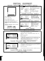
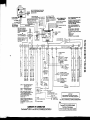
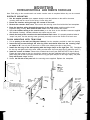
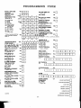
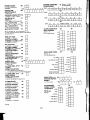
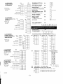
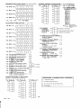
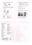
rl
NationaI
Guardian
*
Controlink 3010
SECURITY SYSTEM
INSTALLATION INSTRUCTIONS
N5718 9/11/91
TRADITIONAL
CONTROL/COD IUNICATOR WITH SEPARATE CONSOLE(S)
l
l
l
l
l
l
O
CAN USE WITH 3010,3010-1, OR
3010-2 CONTROL (4 wires)
FIXED WORD, ENGLISH LANGUAGE/
ZONE No., BACKLIT LCD DISPLAY
BUILT-IN SOUNDER
PANIC ALARM
LOW CURRENT DRAIN (20mA)
PULL-OUT ZONE ID DRAWER
4127
ECONOMY (Fixed Word) CONSOLE
.
METAL CABINET
CAN USE WITH 3010,3010-l, OR
3010-2 CONTROL (4 wires)
SAME DISPLAY AS, AND
FUNCTIONALLY SlMlLAR TO,
4127, BUT WITH ENHANCED
STYLING AND BACKLIT KEYS
SURFACE OR FLUSH MOUNTING
l
BUILT-IN ALARM RELAY
BUILT -IN DIALER BOARD
l
L
4137
PLUG-IN POWER PACK INCLUDED
STANDARD (Fixed Word) CONSOLE
9 WIRED ZONES, EXPANDABLE FOR UP TO 64
ZONE POLLING LOOP AND/OR WIRELESS
OPERATION BY ADDING 4152LMB PLUG-IN LOOP
MODULE
CAN USE WITH 3010, OR 3010-2
CONTROL (4 wires)
l
l
REQUIRES AT LEAST ONE CONSOLE (ECONOMY,
STANDARD, OR ALPHA)
Controlink 3010
CONTROL PANEL
l
SlMlLAR TO 4137, BUT WITH
PROGRAMMABLE, ALPHANUMERIC 2 LINE ENGLISH
LANGUAGE. BACKLIT LCD
DISPLAY
SELF-HELP FEATURE
5137
(Ademco No. 4140XM)
ALPHA CONSOLE
SELF-CONTAINED
CONTROL/COMMUNICATOR/CONSOLES
.
.
SELF-CONTAINED (RESEMBLES 4137 STANDARD CONSOLE)
CAN BE SURFACE OR FLUSH MOUNTED
FIXED WORD, ENGLISH LANGUAGE/ZONE NUMBER, BACKLIT LCD
DISPLAY
BUILT-IN 86dB SOUNDER
BACKLIT KEYPAD
.
.
.
ACCOMMODATES PLUG-IN DIALER BOARD (4171XM OR 4171XT-XM)
9 WIRED ZONES, EXPANDABLE FOR UP TO 64 ZONE POLLING LOOP
AND/OR WIRELESS OPERATION BY ADDING 4171XT-XM DIALER
BOARD AND 4152LMB LOOP MODULE
CAN ADD REMOTE CONSOLE(S), ECONOMY OR STANDARD
Controlink 3010-1 FIXED WORD CONSOLE/CONTROL
(Ademco No. 4130XM)
SIMILAR TO 3010-l CONSOLE/CONTROL, BUT HAS PROGRAMMABLE,
ALPHANUMERIC 2 LINE ENGLISH LANGUAGE, BACKLIT LCD DISPLAY
(RESEMBLES 5137 ALPHA CONSOLE)
SELF-HELP FEATURE
CAN ADD REMOTE CONSOLE(S), ECONOMY, STANDARD, OR ALPHA
Controlink 3010-2 ALPHA CONSOLE/CONTROL
(Ademco No. 5130XM)
2
w
l
l
SLIMLINE DESIGN
MAGNET AND BUILT-IN REED SWITCH
(5711 WM ONLY)
l
SELECTABLE FOR OPEN CIRCUIT
l
SELECTABLE FOR FAST RESPONSE
l
USES 9V BATTERY
l
WITH INSTRUCTlONS
5711WM or 5711
DOOR/WINDOW
4280 IDENTIFIES UP TO 63 WIRELESS TRANSMITTERS
PLUS A WIRELESS KEYPAD (5727)
4280-8 IDENTIFIES UP TO 8 WIRELESS TRANSMlTTERS
PLUS A WIRELESS KEYPAD (5727)
200 FT NOMINAL INDOOR RANGE
BUILT IN GO/NO-GO SIGNAL STRENGTH TEST
(PATENTED)
USE 2 PER SYSTEM
2 WIRE CONNECTlON TO CONTROL
2 SNIFFER MODES, FOR HOUSE ID AND TRANSMITTER
ID CHECKS
WlTH lNSTRUCTlONS
l
l
l
l
PULSE COUNT OPTION
3 MINUTE LOCKOUT BETWEEN
TRANSMISSIONS, TO CONSERVE
BATTERY
USES 9V BATTERY
WlTH INSTRUCTlONS
5775
PASSIVE INFRARED
DETECTOR/TRANSMITTER
4 2 8 0 o r 4280-8
WIRELESS RECEIVER (USE 2)
P
n
-
1 BUILT-IN PANIC (24HR,
SILENT OR AUDIBLE)
- TRANSMISSION
VERIFICATlON LED
5727
WIRELESS KEYPAD
*
l
TRANSMITTER
24 HR, SILENT OR
AUDIBLE
* NORMAL OR FAST
RESPONSE
* OPEN OR CLOSED
ClRCUlT
* TAMPERED COVER
b WHlTE OR BROWN
SINGLE BUTTON
OPERATION
5701
PANIC
TRANSMITTER
L
5715WH/BR
UNIVERSAL
TRANSMITTER
* BUILT-IN ALARM
SOUNDER
BUILT-IN AUDIBLE
LOW-BATTERY
WARNING
ONE PIECE DESIGN
9 WlTH INSTRUCTIONS
5706
PHOTOELECTRIC
SMOKE DETECTOR/
TRANSMITTER
l
l
WIRED ZONES (up to 9) can be used with the system. See the Technical Reference Manual for complete
information.
POLLING LOOP DEVICES can be used, up to the system’s total capacity of 64 zones. See the
Technical Reference Manual for complete information.
3
To expand the system for use of wlreless devices and/or a P-wire polling loop, a 4147XT-XM
Dialer Board, and a 4152LMB Loop Module must be Installed In the control, as shown below.
(The 4171XT-XM Is factory Installed In the C o n t r o l i n k 3010 Control Panel.)
4171XT-XM DIALER BOARD INSTALLATION
Remove the Console/Control’s back cover and discard. Insert three small standoffs (supplied) into the three holes
on the Control board (marked A, B and C on the diagram) pressing each until they “snap” into place. Insert the 13-pin
male-to-male adapter (supplied) into the interface socket pin holes on the underside of the Dialer board as shown.
Guide the adapter pins into the pin holes on the Control board, while aligning the standoffs with their respective
holes in the Dialer board. Be sure the adapter pins are properly entering the Control board holes, and press down
until the pins are fully seated and the standoffs “snap” into place.
4152LMB LOOP MODULE INSTALLATION
Note the 8 square-shaped connector pins on the dialer board. Position the 4152LMB board over that board so
that these pins engage the mating sockets (header) on the underside of the 4152LMB. Press the 4152LMB
down until the pins are fully seated. Secure the 4152LMB by means of 3 screws (supplied).
Wires from the 4280/4280-8 receivers are connected to Terminals 1 and 2 on the 4152LMB (as are wires from a
4208 zone expander and remote point modules, if used...see the Technical Reference Manual for full
information).
INSTALLING DIALER BOARD
INSTALLING LOOP MODULE
4
Two 5711WM
DOOR/WINDOW TRANSMITTERS
5775
PASSIVE INFRARED
DETECTOR/TRANSMITTER
/
TWO WIRELESS RECEIVERS
(4286 for up to 63 transmitters, or
4280-8 for up to 8 transmitters)
4137
STANDARD
CONSOLE
Controlink 3010
CONTROL PANEL
(Ademco No. 4140XM)
BASIC 3 ZONE SYSTEM
RECEIVER #1
RECEIVER #2
SUGGESTED EQUIPMENT LOCATIONS
CONTROL PANEL: The best location is usually near the incoming phone block and
close to an AC outlet (probably in the basement or on the first
floor).
CONSOLE/CONTROL
OR REMOTE CONSOLE:
A location that is convenient to the user during entry and exit
should be used.
WIRELESS RECEIVERS: Locate the two receivers to provide redundant coverage, as
described in the instructions that accompany the receivers.
Central, high locations within the premises, either on the first or
second floor, are recommended (not the basement, in large
installations). Do not locate near any large metal object. Do
locate at least 10 feet away from the control, from each other,
and from any remote consoles.
Permissible wlrlng runs (2 wire) per receiver:
up to 2400 ft using #16 gauge
up to 1500 ft using #18 gauge
up to 950 ft using #20 gauge
up to 650 ft using #22 gauge
TRANSMITTERS:
The indoor range in most residential buildings is approximately
200 feet. Keep at least 4 inches away from any large metal
object and do not locate any transmitter inside of a metal
enclosure.
N o t e : Before permanently mounting the transmitters in their
proposed locations, use the Go/No Go (Signal
Strength) Test described on page 17 herein, (and in
the instructions with the receivers), to verify that the
locations will be suitable for transmissions to the
receivers.
6
czxm~RE/~ONUR~R~
AND
WEMIBUE
@rixmlG0RE~
Note: Field wiring to the console/control and remote consoles must be completed before they can be mounted.
SURFACE MOUNTING
1. Use the template provlded (on a separate sheet) to mark the positions on the wall for the screw
2.
3.
4.
5.
6.
mounting holes and the cut-out for the wiring. Cut the wiring hole.
Route the interface wiring through the cut-out In the wall.
Remove the console’s back cover. First remove the securing screw from behind the front nameplate.
Pass the Interface wlrlng through the opening In the back cover and through the 4143
Expansion Ring (if used), then mount the back cover to the wall surface with screws.
Splice the Interface wlrlng to the console wlres (or to the wires on the interface connector supplied
with Standard Consoles). Insulated solderless wire splices may be used.
Attach the body of the console to the wall-mounted back cover. It is properly attached when it
“snaps” into place. Use the securing screw (previously removed) to secure the console to its back cover.
FLUSH MOUNTING WITH TRIM RING
1. Cut an opening In the wall (see Diagram A below). Use the template provided to mark the opening.
2. Insert the four screws through the trim ring holes and thread them Into the securing clips
as shown In “B”. Use only two or three turns of each screw, allowing the clips to hang freely.
3 . Install the trlm ring In the wall openlng with the hlnge clasps to the rlght (see “D”). Straighten
the trim ring and tighten each clip’s screw, making sure that each clip moves down into its guide track (see “C”).
4. Install the console as follows: Remove the console’s back cover (see SURFACE MTG. Step 3 above).
Engage the hinge clasps on the trim ring with the notches in the back (right-hand side) of the console’s front
panel. Swing the left side of the panel toward the trim ring (the panel will pivot on the hinge clasps), and press
firmly until the panel “snaps” closed.
5. Secure the left side of the panel with the securing screw supplied. Replace the nameplate.
METAL
SECURING
CLIP
FOR CLARITY.
ONLY ONE
CLIP SHOWN
IN THIS
ILLUSTRATION
1
! ; ;_,
STUDS
HINGE CLASPS
(MUST BE ON
II
No. 6 x 1 112”
SCREWS 14)
TRIM RING
(INSTALLED IN WALL,
8
I1
POWER-UP PROCEDURE
1. Wire the 1350 (1360) DC POWER PACK first (before the battery), making sure polarity is correct and
the terminal strip (or harness) is connected to the control as shown in the Summary of Connections diagram.
Do not plug in the power pack or connect the battery at this time!
2. Connect all auxiliary devices, such as consoles, PIRs, etc.
3 . Ground Connectlons: In order for the protective devices in this product to be effective, the designated
earth ground Lead or Terminal must be terminated in a good earth ground. The following are examples of
good earth grounds available at most installations:
Metal Cold Water Pipe: Use a non-corrosive metal strap firmly secured to the pipe to which the
ground lead is electrically connected and secured.
AC Power Outlet Ground: Available from 3-prong, 125VAC power outlets only. To test the integrity
of the ground terminal, use a three-wire circuit tester with neon lamp indicators, such as the UL Listed Ideal
Model 61-035, or equivalent, available at most electrical supply stores.
3. Plug the 1350 (1360) Into an AC outlet. Check that the Auxiliary Voltage measures between 13.5
and 14.0VDC. If under 13.5V, too much current is being drawn from the control. See the SPECIFICATIONS
section of the Technical Reference Manual for the current draw of each device.
4. Connect the battery as shown in the Summary of Connections diagram. Do not connect the battery if
Auxiliary Voltage is below 13.5V, as this will prevent the battery from being fully charged.
PROGRAMMING THE SYSTEM
1 . ENTER THE PROGRAMMING MODE in either of these two ways:
A. lmmediately (within 30 seconds) after powerlng up the system, depress the keypad’s
[*] and [#] keys at the same time.
or
B. With power previously applied, enter the INSTALLER CODE + [8] + [0] + [0].
Note: The INSTALLER CODE is initially “4140” for the 3010 (or “4130” for the 3010-1, or “5130” for
the 3010-2), but may subsequently be changed (via programming field *00...see page 11).
2. INITIALIZE THE CONTROL TO ONE OF THE PROGRAMMING DEFAULTS
The system is shipped with a set of pre-programmed values that are designed to meet the needs of many
installations. These can be changed by the installer to suit specific needs if desired. Alternatively, one of four
sets of pre-programmed communication default values can be loaded by the installer, each set designed for a
specific communication format. These too can be changed to suit the needs of a particular installation.
Changes to these pre-programmed values can be programmed directly from the keypad, or remotely from a
computer terminal using DOWNLOADING. See the Technical Reference Manual for instructions.
Load one of the default programming sets by using the following chart. (Note: One of these sets
must be entered before any other field entries are made.) A complete list of the default values can be found in
the Technical Reference Manual.
9
3. PROGRAMMING PROCEDURE
The control has two sets of programming fields. One set contains the fields indicated by *00 through *90 on the
Programming Form. The other contains the fields indicated by 1*00 through 1*49 on the Programming Form.
The *00-*90 Set is accessible as soon as the control enters the programmlng mode. FixedWord consoles will simply display the field address. Alpha consoles will display: PROGRAM MODE and a
hyphen will be displayed in front of subsequently entered field addresses.
To program a field within this set, enter: [*] + Address (00-90). For example: [*] + [3] + [3] when
assigning the Primary Phone Number. Then make the required entry. The console will beep when a field has
been completely programmed and will automatically display the next data field in numerical order.
To view a field, enter: [#] + Address. For example: [#] + [3] + [3] to view the Primary Phone Number. The
field’s entries will be displayed, but no changes to these entries can be made.
To switch to the 1*00-*1*49 Set, enter: [*] + [9] + [4]. The word CHECK will be displayed at FixedWord consoles if this set has been accessed. Alpha consoles will display: ALT PROGRAM MODE and a “1” will
be displayed in front of subsequently entered field addresses.
To program a field within this set, enter: [*] + Only the last two dlglts of the Field Address. For
example: [*] + [1] + [9] for field 1*19. Then make the required entry.
To vlew a field, enter: [#] + only the last two dlglts of the Field Address. For example: [#] + [1] + [9]
for field 1 *19.
To return to the *00-*90 Set, if desired, enter: [*] + [9] + [9], noting that the word CHECK
disappears from the display (or ALT PROGRAM MODE changes to PROGRAM MODE).
For Alpha consoles and controls, English language descriptions of the zones and a custom installer
message (which appears when the system is ready to arm) can be programmed. Refer to the Technical
Reference Manual for details.
4. TO EXIT THE PROGRAM MODE enter: [*] + [9] + [9] ONCE (if exiting from the *00-*90 Set) or TWICE
(if exiting from the 1*00-1*49 Set).
If necessary, the PROGRAM MODE may be re-entered by entering: INSTALLER CODE + [8] + [0] + [O].
Note: Re-entry to PROGRAM MODE via the installer code can be prevented by entering: [*] + [9] + [8]
when exiting (preceded by an entry of: [*] + [9] + [9] if exiting from the 1’00-1’49 Set). Then
PROGRAM MODE can only be re-accessed by depressing the [*] and [#] keys at the same time,
within 30 seconds after power-up.
10
10
GO/NO GO (SIGNAL STRENGTH) TEST
Use this test to help determine the best location for each wireless transmitter before mounting it permanently in
place. During the test, the receivers’ sensitivity is reduced by half, thus assuring strong reception of signals during
normal operation of the system.
1. Place the system in the Test Mode (enter: SECURITY CODE + [5]) and remove both
receivers’ covers.
2 . Place transmitters temporarlly In thelr proposed locatlons. If wire is to be run from any transmitter,
temporarily connect an equivalent length of wire to its screw terminals.
3 . Trip each transmitter, one at a time. A successful test will result in both receivers “hearing” the
transmitter. This will be indicated by the console beeping three times and displaying the transmitter ID. Only
one beep lndlcates that only the “first” receiver heard the transmitter and two beeps Indicate that only
the “second” receiver heard the transmitter. If necessary, reorient or relocate the transmltter to
obtain a successful test (sometimes moving only a few inches will be necessary). Note: Do not conduct
these tests with your hand wrapped around the transmitter.
4. To exlt thls mode replace the receivers' covers and enter: SECURITY CODE + [OFF].
AFTER THE INSTALLATION IS COMPLETE,
THE SECURITY SYSTEM SHOULD BE THOROUGHLY TESTED, AS FOLLOWS:
USING TEST MODE
1. Wlth the system In the disarmed state, check that all zones are Intact. If “NOT READY” (FixedWord consoles) or “DISARMED-Press [*] to show faults” (Alpha consoles) is displayed, press the [*] key to
show the descriptors of the faulted zone(s). Restore any faulted zones so that “READY” (Fixed-Word
consoles) or “*‘**DISARMED**** READY TO ARM” (Alpha consoles) is displayed.
2 . Place the system In the Test Mode (enter: SECURITY CODE + [5]). The external sounder, if
used, should sound for 3 seconds and then turn off. The system is operating on the back-up battery only at
this time.
Notes: A. The system will not enter the Test mode if the battery voltage is too low, if the battery is not
connected, or if any communication messages are waiting to be transmitted.
B . As a reminder that the system is in the Test mode, the Console will sound a single beep at
15-second intervals if no protection zones are violated.
C . In the Test mode, no alarm reports will be sent to the central station. Also, the external
sounder, if used, will not be activated.
3 . Activate each sensor, one at a time. Each action should produce three beeps from the Console
and the descriptor for the protection zone should appear on the Console display while activated.
Notes: A. Open and close each protected door and window in turn.
B. Walk in front of any interior motion detectors. Note that wireless PlRs have a 3 minute lockout
between transmissions to conserve battery life.
C. For smoke detectors, follow the test procedure provided by the manufacturer, to ensure that
all detectors are operational and are functioning properly. Note that a 2-wire smoke detector
display will not clear until the Test Mode is exited.
4 . To exit the Test Mode, enter: SECURITY CODE + [OFF].
17
ARMED SYSTEM TEST
IMPORTANT! A message will be sent to the central statlon during the followlng tests. Notify
them In advance that a test will be In progress.
Note : A display of “COMM. FAILURE” (Alpha consoles) or “FC” (Fixed-Word consoles) indicates a failure to
communicate (no Kissoff by the receiver at the central station after the maximum number of transmission
attempts is tried).
1 . Arm the system and fault one or more zones. Silence alarm sounder(s) each time by entering:
SECURITY CODE + [OFF]. Check that Entry/Exit delay zones provide the assigned delay times.
2. Check the keypad-lnltlated alarms, if programmed in field *05, by pressing the Panic keys ([*] and [#],
[1] and [*] and/or [3] and [#]. If the system has been programmed for audible emergency, the console will emit
a loud, steady alarm sound. The word “ALARM” and a descriptor “99” will be displayed for [*] and [#] (or.“95"
for [1] and [*], or “96” for [3] and [#]). Silence the alarm by entering: SECURITY CODE + [OFF]. If the system
has been programmed for silent panic, there will be no audible alarms or displays; however, a report will be
sent to the central station.
3. Notlfy the central statlon when all tests are finished and verlfy results with them.
IMPORTANT!: In the spaces provided in the User’s Manual, record the Entry and Exit Delav times, and
those functions that have been programmed into the available pairs of Panic keys ([*] and [#],
[1] and [*], [3] and [#]).
1. Fully explain the operatlon of the system to the user by going over each of its functions as well as
the User’s Manual supplied.
2. In particular, explain the operatlon of each zone (entry/exit, perimeter, interior, fire, etc.). Be sure
the user understands how to operate any emergency feature(s) programmed into the system.
3. Make sure the user understands the Importance of testlng the system at least weekly,
following the procedure provided in the User’s Manual.
TO THE INSTALLER
Regular maintenance and inspection (at least annually) by the installer and frequent testing by the user are vital to continuous
satisfactory operation of any alarm system.
The installer should assume the responsibility of developing and offering a regular maintenance program to the user, as well as
acquainting the user with the proper operation and limitations of the alarm system and its component parts. Recommendations
must be included for a specific program of frequent testing (at least weekly) to insure the system’s operation at all times.
18