1
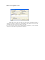
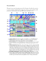
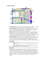
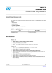
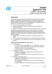
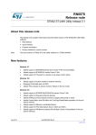
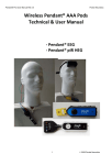
Operating User Manual for the
Deymed Brainfeedback 3 System
This manual is designed to explain the features and function of the Deymed
Brainfeedback 3 software. The following user’s manual will guide you
through the functions and applications of the various software features.
Deymed reserves the right to make changes or updates to this manual at any
time.
©
2005 Deymed Diagnostic Inc. All rights reserved. This manual and the software
described herein, in whole or in part, may not be reproduced or translated without prior
written approval.
User Instructions for Deymed
Brainfeedback 3
Brainfeedback 3 ver. 11.02.XXX
Brainfeedback 3 screen:
1.
2.
3.
1. Add or Edit patient’s card button: New Patient button: Opens the “Work with
Patient’s Data” dialogue box for a blank patient. Edit Patient’s Card button: Opens
the “Work with Patient’s Data” dialogue box for the currently selected patient. See the
New Patient Card section below.
2. Patients List: Shows the current patients in the system sorted alphabetically
ascending by surname.
3. Patient Recording List: Shows the recordings available in the system for the
currently selected patient.
Edit / create patient’s cart:
When adding a new patient, click the “new patient” button, the minimum amount of
information required is a surname and a patient ID number. Only numbers can be used for the
patient ID. The system will not allow duplicate patient ID’s.
If you select an existing patient, and press the Edit Patient’s Card button, you may edit all the
information in this window except the Patient’s ID number.
Session results:
This panel enables operator to view the results of the so far sessions with a
selected patient and their printing.
2.
1.
3.
1. Recording list: To view the session results for the selected patient: First find the line
with the desired session. If the line is not visible, scroll down the patient list using the
up and down arrows on the right-hand side of the list or shift the sliding bar between
the arrows. Next, click on the desired session line. The respective results will appear in
the right-hand half of the panel.
2. Results of the selected sessions: Shows the electrode selected, the level of micro
volts, preset goals for each band, the length of each round and the score.
3. Print results: To print the results of the patient’s session, first select the session to be
printed and then click on the Print Results button. The printer setting dialog box will
appear. If necessary, select the Windows printer. The preview of the result report will
appear on the screen. Using the buttons at the top of the screen, you can change the
size of the report in three stages or skip between individual pages in the event the
report is multi-page. To print the results, click the printer symbol. To cancel the print
preview, click the Exit button.
Neurofeedback:
This panel represents the primary part of the Program. It enables the operator
to select a training method and the games to be used, to set the training round
parameters and to monitor the rough EEG and its individual scales.
8.
9.
10. 11.
12. 13. 14.
15.
1.
2.
16.
3.
17.
4.
5.
18.
6.
19.
7.
1. Selected channel: Select the raw signal you would like to see in the EEG diagram
2. EEG diagram: Displays the raw EEG signal. When this display turns blue, the
patient is meeting or has met the requirements for reward and inhibit.
3. Protocol Selector: To use a Standard protocol, select it from the list. To use a custom
protocol, select the custom toggle button, then select the pre-prepared protocol to be
used.
4. Site/Bandwidth Info Panel: The positive and negative electrodes and the bandwidth
for that particular scale window are listed here. i.e. EEG1(C3) – Ref: Theta. It is very
important to verify that the correct electrode channel and bandwidth are being used for
each treatment. This information can be adjusted in the training setup for custom
protocols, but is fixed for the standard protocols. For the standard protocols, the only
change available is the Electrode Channel being used, changeable by choosing from
the drop down menu as above in the Site Selector section of this list.
5. Recording control buttons: Controls for starting, pausing, and stopping a recording
6. The new games roll-down menu selection and old 2D games list: Select the desired
3D game from the drop down menu. If using the old 2D games, they may be selected
from the drop down menu in the bottom right hand corner. If using a dual monitor
setup, the games will appear on the 2nd monitor. To configure dual monitor settings,
right click on the desktop of the main computer and select “properties.” Select the tab
marked “settings.” If the 2nd monitor is connected to the computer, the display will
show a “1” and a “2.” Click on the “2” and select “Extend my Windows desktop onto
this monitor.” Set the “screen resolution” to 1024x768 pixels. Click “apply” and
close the box.
7. Setting the parameters of the game training round: Select the amount of rounds,
round length and delay level. A high number for “delay level” will allow the patient
to score points very easily and a low setting will be more accurate. The default setting
for “delay level” is a good balance between accuracy and ease of scoring.
8. Exit Button: Used to exit the program and shut down the BFB Headbox
9. Session Info: Displays the time that has passed in the current game round and the
round number
10. EEG diagram parameters: set the sensitivity, low and high pass filters for the EEG
diagram
11. Spectrum: Displays all the amplitudes for the selected electrode for the frequencies
from 1 – 50Hz
12. Paper Speed: Set the speed of the graph on the EEG diagram
13. Auto goals: During or before the training you can set the thresholds for the user
manually or you can use the auto goals. These are set in the “training setup” tab
described in the next section.
14. Record EEG: Select this option before you start recording to save the raw EEG
recording to a file for later review in Neuroguide or Deymed TruScan Explorer. The
record is saved on the records folder on the primary hard drive.
15. Impedance meter: gives a continuous real-time output of the state of the connection
to the patient’s head.
The meter reads in KiloOhms (kΩ), and is color coded for easy reading.
The color coding is as follows:
<5 kOhm
impedance)
5 kOhm to 10 kOhm
11 kOhm to 30 kOhm
>30 kOhm
disconnected
Blue
High quality connection (very low
Green Good connection
Yellow Poor connection
Red
Unusable connection or electrode
16. Scale Windows: There are 6 scale windows, each one assigned to a separate
bandwidth (either standard or custom). The window consists of a real-time graph of
Amplitude versus Time for that particular bandwidth, a threshold slider bar, a
Site/Bandwidth info panel, and an average readout. The graph will be grey when the
amplitude is below the slider and colored when above.
17. Average Readout: There are two average readouts separated by a slash. The leftmost
is a short period average showing the state over the last second. The rightmost is the
running average for the entire session.
18. Y-Axis Scale Selector: Select the maximum micro voltage for this scale window
19. Adjusted target [µ
µV]: Set the threshold for each band. For the band that you want to
reward, set the threshold below the average readout in microvolts. For the band/s that
you want to inhibit, set the threshold above the average readout in microvolts. The
most common settings are to reward SMR and to inhibit Theta and Beta2.
Training Setup:
5.
1.
6.
2.
3.
7.
4.
1. Custom Protocols: To create a new custom training, click “new training.” A pop up
window will appear. Enter a name for the new training and click “ok.”
2. List of Created Protocols: After creating a new training, the name automatically
appears in the list. Select a training from the list and either modify it using “scales
setup” or delete the training with the button “delete training.”
3. Scales setup: Select the band, the electrode you would like to assign to that band,
game parameter (reward or inhibit) for that band, and the color the graph should be
displayed in. If you would like to train coherence, instead of selecting an electrode,
select coherence. When training coherence, you need 5 electrodes (1 reference on each
ear, 1 ground anywhere and 2 active electrodes for the sides you will train)
4. Artifact Rejection: Press this button if you would like the program to reject artifacts
in a recording. When this is selected, the round will be extended by the time that
artifacts were present. For example, if the patient’s recording has one minute of
artifacts and it would normally be a five minute round, the total round time will then
be six minutes.
5. Global bands
• Standard bands: If desired, select a different frequency range for a given
band
• Custom bands: If you want to create a custom band(5 characters long),
rewrite the name and select a frequency range
6. Main Sound: Set the sound the game produces when the patient meets the training
requirements
7. Autogoals: These displayed numbers are for the auto threshold setup and it is a
percentage of the current average read out. So for example if you are obtaining 10uV
as an average and the auto goals are set to 100% the threshold will be adjusted to
10uV. If you set it to 80% than the threshold will be at 8uV and patient will be above
threshold for reward. If you set it to 120% for inhibit and you have reading of 10uV,
the threshold will be set to 12uV and the patient will be below the threshold for
inhibit.
Notes:
This panel serves for writing notes for the selected patient.
Headbox BFB2-4ch:
The Diagnostics panel serves for monitoring the device status, for testing the device
and/or for identifying possible defects.
To use the new 3D games it is necessary to enter a valid Game code, click on Submit
button and then restart the application.