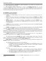
1
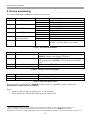
Asteroid
The channels bank for Asterisk/CallWeaver
User’s manual
Version 2.1
22.03.2010
Asteroid user’s manual
© PARABEL, ltd
ALL RIGHTS RESERVED
ASTEROID USER’S MANUAL
PARABEL LIMITED
P.O. BOX 126
NOVOSIBIRSK-90
RUSSIAN FEDERATION
Web:
http://parabel-labs.com
Email:
[email protected]
Phone/Fax: +7-383-2138707
2
Asteroid user’s manual
Attention! It is not recommended to use this product on physical lines
without lightning protectors.
3
Asteroid user’s manual
Table of contents
1. Introduction...............................................................................................................................................5
1.1 TDMoE module internals ...................................................................................................................7
1.2 The Ethernet connection notes............................................................................................................8
2. Technical characteristics...........................................................................................................................9
2.1. General parameters ............................................................................................................................9
2.2. E1 parameters ....................................................................................................................................9
2.3. Ethernet parameters ...........................................................................................................................9
2.4. FXS and FXO ports parameters.........................................................................................................9
2.5. Console port parameters (RS232)....................................................................................................10
3. Bank installation .....................................................................................................................................11
3.1. Sockets, indicators, switches............................................................................................................11
3.2. Sockets description ..........................................................................................................................11
4. Device configuration...............................................................................................................................13
4.1. Connecting console..........................................................................................................................13
4.2. The main configuration menu..........................................................................................................13
4.3. General settings................................................................................................................................13
4.4. E1 port settings ................................................................................................................................14
4.5. FXS/FXO ports settings...................................................................................................................14
4.6. Saving and restoring parameters......................................................................................................15
4.7. Testing and diagnostic tools ............................................................................................................15
5. Device monitoring ..................................................................................................................................16
6. Attaching to PBX/Asterisk .....................................................................................................................17
6.1 Introduction.......................................................................................................................................17
6.2 Configuring DAHDI for Asteroid attaching .....................................................................................17
6.3 DAHDI synchronization ...................................................................................................................18
6.3.1 Synchronizing DAHDI – Asteroid is master .............................................................................19
6.3.1 Synchronizing DAHDI – Asteroid is slave................................................................................20
6.4 DAHDI/dahdi_dynamic statistics .....................................................................................................20
6.5 Step by step configuration ................................................................................................................21
6.6 Attaching Asteroid with help of E1 port...........................................................................................23
6.7 Patches for DAHDI...........................................................................................................................23
7. Point to point connection ........................................................................................................................25
7.1. Variant of Ethernet connection ........................................................................................................25
7.2. Variant of E1 connection .................................................................................................................25
8. Hardware echo canceller.........................................................................................................................26
9. Updating firmware ..................................................................................................................................27
10. Asteroid delivery...................................................................................................................................27
Appendix А. Application schemes .............................................................................................................28
Corporate PBX with VOIP connection...................................................................................................28
Appendix B. Example of system.conf file ..................................................................................................29
Appendix C. Asteroid + DAHDI – steps to check.....................................................................................30
4
Asteroid user’s manual
1. Introduction
The channel bank is a 19’’, 1U height unit. It consists of four 8 port FXS or FXO modules.
Asteroid can be used for attaching up to 30 telephone clients to the traditional PBX or to any
DAHDI-compatible PBX like the Asterisk/CallWeaver. It can be connected to the traditional PBX with
the help of E1 interface. Connection with Asterisk can be made through Ethernet port, using TDMoE
protocol. In both cases the channel bank realizes Loop Start signalization, subset of CAS family
signalizations. Moreover, Point to point mode can be provided if Asterisk server is not used.
Further in the text we assume Asterisk and CallWeaver to be equivalent.
Figure 1. Internal Asteroid architecture
Consider internal architecture of the bank in detail (Figure 1).
Internal modules of Asteroid are interconnected by several buses: a control bus, a signaling bus,
data bus. The control bus is used for initialization and monitoring of modules. The signaling bus is used
for transportation of telephone signalization between FXO/FXS modules and framers. The data bus is
used for voice transmission and synchronization.
The E1 or TDMoE framers provide interfaces for Asteroid attaching to PBX or Asterisk. In the
receive direction framer processes digital data, arriving from PBX or Asterisk. It synthesizes voice and
signaling streams on buses. In the transmit direction framer forms the digital stream to be sent to the
PBX or Asterisk.
Synchronization obtained by the framer is used for syncing all Asteriod modules. If Asteroid is
slave relative to the Ethernet port, TDMoE framer adjust its frequency to the packets rate, using phase
locked loop technique.
Signalization from data and signaling buses follows to FXS/FXO modules. In correspondence
with this information, modules set up the telephone ports states and decode the A/m law encoded data
stream. In the reverse direction, these modules process the analog lines modifications and encode the
voice to data stream.
FXS modules can recognize the hook off state, the pulse dialing. They form the ring signal. FXO
modules can recognize the ring signal from PBX and dial number. The tone dialing is passed through
without processing.
5
Asteroid user’s manual
Microcontroller is used for setting parameters, displaying the status information and firmware
loading.
Consider Asteroid and Asterisk interaction over Ethernet. Asteroid transmits TDMoE packets
through Ethernet. Packets received by the server go to the DAHDI driver. If necessary, it cancels the
echo and passes the voice and signalization to Asterisk. Processing these data, Asterisk functions like a
traditional PBX or VOIP. In the reverse direction, DAHDI driver receives voice and signalization from
Asterisk, packs them to TDMoE packets and transmits the packets to Ethernet.
To sum up, Asteroid delivers voice and signalization between FXS/FXO and Ethernet (E1) ports,
not touching the signalization logic itself. The signaling logic is processed by Asterisk or by any other
PBX connected to Asteroid.
The four 8-channel FXS/FXO cards provide 32 telephone ports, but only 30 ports are available.
The reason is the structure of E1 frame. E1 stream uses channel intervals 0 and 16 for frame signaling
and ABCD bits (encoded state of telephone lines). The corresponded ports 0 and 16 can’t be used.
It is worth mentioning that, while using Ethernet connection, the channel bank can be hot
replaced without Asterisk server restarting. If Asterisk server is reserved by the second server, both of
them can use common pull of Asteroid banks. This reduces the total system cost.
Asteroid order codes (*):
Item
Asteroid-0L4S
Asteroid-4L0S
Asteroid-1L3S
Asteroid-0L4S-EC
Asteroid-4L0S-EC
Asteroid-1L3S-EC
Asteroid-0L4S-E1
Asteroid-4L0S-E1
Asteroid-1L3S-E1
FXS ports
FXO ports
E1
30
0
22
30
0
22
30
0
22
0
30
8
0
30
8
0
30
8
+
+
+
Table 1. Order codes
* In all variants Ethernet port is present.
6
HW echo
canceller
+
+
+
-
Asteroid user’s manual
1.1 TDMoE module internals
For converting TDM bus to packets, data is collected in one of two DB buffers (see ”Figure 2.
TDMoE module structure”). The data from other previously filled buffer is passed to Ethernet using
TDMoE format. One Ethernet packet contains 8 TDM frames. The corresponded packet rate is 1 kHz.
FRAclk
E1txClk
Ethernet
Rx
Ring buffer
(RB)
TDM
bus
Ethernet
Ethernet
Tx
Double buffer
(DB)
Figure 2. TDMoE module structure
For reverse conversion, TDMoE packets are collected in the ring buffer RB with volume of 8
packets (8* 30 * 8 bits). The structure of the buffer is shown on “Figure 3. Ring buffer”. The PntW
pointer marks the following free buffer for writing and incremented by one when the new packet is
received.
In the same time the data is extracted from the ring buffer and passed to the TDM bus. The PntR
pointer marks the following packet for reading and incremented by one after current buffer transmitting
to the TDM bus.
PntW
7
5
PntR
7
0
6
4
PntW
1
6
2
5
4
3
PntW
7
0
1
6
2
5
3
PntR
0
1
4
2
3
PntR
Figure 3. Ring buffer
For PntW to work perfectly, it should pass ahead PntR by half of RB buffer volume. But in
reality, the average rate of Ethernet packets differs from the TDM packets rate. The last one is defined by
the internal frequency E1txClk.
If PntR pointer reaches PntW+1 value, PntR is incremented by 3. As a result, two packets (one
E1 multiframe) will be lost. This occasion is named a skip and is displayed in error counter
SkipErr=SkipErr+1.
If PntR pointer reaches PntW-1 value, PntR is decremented by 2. As a result, two packets (one
E1 multiframe) will be transmitted twice. This occasion is named a slip and is displayed in error counter
SlipErr=SlipErr+1.
The slip (skip) rate is defined by the difference between the packets reception rate and TDM bus
transmit frequency E1txClk. For example, if the difference is 15 ppm, the slip rate is equal to one per
7
Asteroid user’s manual
minute. This slip will be detected as a click in sound channel. If the channel is occupied by a fax or a
modem, the lost of data portion may occur. Effective speed of connection will be lower.
To eliminate slips Asterisk should be synchronized to Asteroid.
The second possibility to eliminate slips is to enable PLL regulator FRAclk. In this case Е11 port
should have ‘clock=internal’ setting. The regulator is controlled by ring buffer pointers. If PntW and
PntR difference is equal to 4, E1txClk is equal to the internal quartz frequency divided by 12 (24576/12 =
2048 kHz). When the difference has other values, the E1txClk period is shortened or extended once per
millisecond by value 40 ns * VCO. The configuration parameter VCO2 can be defined by user as 0 (no
regulation), 1 (regulation with frequency difference less than 40 ppm) or 2 (regulation with frequency
difference less than 80 ppm).
If VCO=1, the jitter (at 125 hz) of the transmit stream is equal to 0.08UI, if VCO=2, then jitter
equals 0.16UI. Both values satisfy ITU recommendation G.823.
The VCO parameter has one more diagnostic application. If VCO=80, the statistic field SkipErr
will display the maximal period between Ethernel packets in microseconds. When Asterisk is first time
started or there are problems with bank synchronization, it is recommended to measure this period. If the
period is more than 1500, the jitter of Ethernet packets is large. This can be caused by software
components, incompatible with real time applications like Asterisk (for example, X11). Also large jitter
can cause the slip or skip errors increment.
As a rule, in synchronized systems one of devices is the clock master.
Example. Let us have two banks of channels (Asteroid_1, Asteroid_2) and Asterisk server.
Asteroid_1 should be configured as clock=internal, VCO=0, TDM over Ethernet. Asterisk should be
synchronized from the TDMoE stream of Asteroid_1. The second bank Asteroid_2 should be configured
as clock=internal, VCO=2, TDM over Ethernet. Asteroid_2 will be leaded by Asteroid_1.
1.2 The Ethernet connection notes
The TDMoE protocol is realized on Ethernet MAC level. On this reason, routers are not allowed
between Asteroid and server. Switches and hubs can be used for connection only.
There are high demands to QoS discipline – packets delay jitter must be less than 1.5 ms.
In practice it is necessary to use the separate port Ethernet in the server, which can be connected
to several channel banks. The other network traffic is undesired in this segment. The number of nodes in
the 100 Mbit network is restricted by 20. But the real number of banks attached to the server is defined
by performance of the server.
1
2
In the mode ‘TDM Over Ethernet’ TDM bus takes role of internal E1 port.
See 4.3. General settings
8
Asteroid user’s manual
2. Technical characteristics
2.1. General parameters
Parameter
Dimentions
Weight
Power consumption
Ambient temperatures
Storage and transportation temperatures
Humidity
Power voltage (AC socket)
Value
430x250x45 mm
3 kg
50 wt
+5°С to +45°С
-40°С to +70°С
Less then 80%
220V +- 20%
2.2. E1 parameters
Parameter
Connector type
Cable type
Nominal pulse voltage
Data transmission speed
Coding
Signal attenuation, not more
Corresponding standard
Pulse form
Phase jitter
Frame structure
Value
RJ45, 8 pins
Symmetrical twisted pair, 120 ohm
3 V +- 10%
2048 kbit/s +- 50 ppm
AMI/HDB3
-40 db
ITU G.703, G.704, G.706, G.732, G.823
Rec. G.703
Rec. G.823
Rec. G.704
2.3. Ethernet parameters
Parameter
Connector type
Cable type
Data transmission speed, mbit/s
Corresponding standard
Work modes
Value
RJ45, 8 pins
Symmetrical twisted pair (UTP)
100
IEEE 802.3
Duplex, Half duplex, Auto negotiation
2.4. FXS and FXO ports parameters
Coding
PCM A-law (ITU-T G.711)
PCM µ-law (PUB-43801)
Nominal signal level
Nominal line impedance
Echoed signal (300..3400 Hz), FXS
Echoed signal (300..3400 Hz), FXO
Gain-frequency variation (respectively to 1 kHz)
in range 300..3400 Hz
Noise level
Loop current (FXS)
Ring voltage (FXS)
0 dBm +- 0.5 dB
600 Ohm
Less than -20 dB
Less than -12 dB
+- 1 dB
Less than -47 dBm
20 mA
100 V (peak-to-peak), 25 Hz
9
Asteroid user’s manual
2.5. Console port parameters (RS232)
Parameter
Work mode
Data speed, kbit/s
Flow control
Electrical signals parameters
Value
Asynchronous, 8N1
38400
No
Rec. ITU V.28
10
Asteroid user’s manual
3. Bank installation
3.1. Sockets, indicators, switches
There are the following features on the face panel (left to right):
• 4 FXS/FXO modules, J1-J4
• Reset switch
• Alarm led, red light - alarm
• 6-pin console socket RJ-11
• 8-pin Ethernet socket RJ-45
• Ethernet link led
• Ethernet Activity led
• 8-pin E1 socket RJ-45
Figure 4. Face panel
There are the following features on the back panel (left to right):
• Power socket (AC, 220V)
• Fuse
• Power switch
• Fan
• Grounding contact
Figure 5. Back panel
3.2. Sockets description
Pin
1
2
3
4
5
6
7
8
Net
RX+
RXTX+
TX+
Ground
Table 2. E1 pinout
11
Asteroid user’s manual
Pin
1
2
3
4
5
6
7
8
Net
TX+
TXRX+
RX-
Table 3. Ethernet pinout
Net
Line 0, tip3
Line 0, ring
Line 1, tip
Line 1, ring
Line 2, tip
Line 2, ring
Line 3, tip
Line 3, ring
Line 4, tip
Line 4, ring
Line 5, tip
Line 5, ring
Line 6, tip
Line 6, ring
Line 7, tip
Line 7, ring
Ground 4
Ground
Pin
1
14
2
15
3
16
4
17
5
18
6
19
7
20
8
21
13
25
Table 4. J1-J4 pinout (FXS/FXO modules)
Warning! Do not use the port 0 of jacks J1 and J3 (FXS/FXO lines 0 and 16).
See “4.5. FXS/FXO ports settings” for the details.
Pin
1
2
3
4
5
6
Net
RXD
TXD
GND
GND
Direction
Out
In
Table 5. Console pinout
3
4
J1 pinout is presented. For J2 line numeration is started from line 8, for J3 – from line 16, for J4 – from line 24.
Protecting ground.
12
Asteroid user’s manual
4. Device configuration
4.1. Connecting console
The console port is connected to COM port of compute with the help of the converting cable RJ11 ÅÆ DB-9. The terminal program should be started on the computer with parameters 38400, 8b, 1s,
np, flow control=off.
4.2. The main configuration menu
After the power is on (or reset) Asteroid prints the main menu to the console and waits for a
command. To configure the channel bank, user should walk through the hierarchical menu system and
choose the necessary parameters. After parameters modification, settings should be saved in non-volatile
memory. There is the dedicated menu point for this.
Screen is separated into two parts.
In the upper part the following information is displayed:
• Software release
• Firmware release
• The major settings and lines status
In the lower part of the screen the current menu is printed (see “Figure 6. The main menu”).
Asteroid monitor, v0.30 19/11/2007, Updates: http://parabel.ru/
Firmware: Asteroid{0xB}, Revision: 0x3, Temperature(C): 27
E1/A Cfg: Line code=HDB3, Clock=Internal, CRC4=On
Slots {0: ALaw,FXS 1: ALaw,FXO 2: ALaw,FXS 3: ALaw,FXS}
E1/A status: LOS=Off, LOF=Off, LOM=Off, LOC=Off, RAIS=Off, FrErr=0/0
TDMoE {status : SkipEr=0, SlipEr=0, RxNuEr=0 <> mac: 005555555500}
1 3 5 7 9 1 3 5 7 9 1 3 5 7 9 1
FXO/FXS state:
BBBBBBB........................
1.
2.
3.
8.
9.
Configuration >>
Status >>
Test >>
Start bootloader
Reset
Figure 6. The main menu
To choose menu points, use number 0-9. Other keys are ignored.
For exit to the upper menu level, press 0.
4.3. General settings
Configuration/Common/VCO – setting PLL parameters.
VCO = 0 – no frequency regulation
VCO = 1 – frequency regulation with +-40 ppm limit.
13
Asteroid user’s manual
VCO = 2 – frequency regulation with +-80 ppm limit
VCO = 80 – diagnostic mode: SkipErr field will display maximal interval between Ethernet packets in
microseconds.
PLL nominal frequency 2048000 Hz
PLL works only with TDMoE stream, and if “Configuration/E1/Clock source = Internal”.
Configuration/Common/MAC – setting Ethernet MAC address. User can arbitrarily choose MAC
address. Nevertheless all TDMoE devices in one network must have unique address.
Configuration/Common/EC – turn on or turn off hardware echo canceller. This option of models with
embedded echo canceller.
Configuration/Common/E1 – turn on or turn off E1 port for connection with server. In the same time
only one port can be used for connection (Ethernet or E1).
Configuration/Common/DST MAC – destination address. If this field equal 0, the address is detected
automatically. In this case the channel bank responds to packets of the first connected server. If this field
not empty, the packets are transmitted and received only from defined address. DST MAC field should
be defined for point to point connections.
4.4. E1 port settings
Configuration/E1/Line code – E1 line code (AMI or HDB3).
Configuration/E1/Clock source – E1 master (Internal) or E1 slave (Line) choosing.
Configuration/E1/CRC4 – turn on or turn off CRC4 generation
4.5. FXS/FXO ports settings
FXS = Foreign Exchange Subscriber = the ring and loop current generating port
FXO = Foreign Exchange Office = telephone line port
Slot
Socket
Slot 0 J1
Slot 1 J2
Slot 2 J3
Slot 3 J4
Port numbers
E1 projection (Channels starts with 0)
0
1-7
8-15
16
17-23
24-31
absent
1-7
8-15
absent
17-23
24-31
TDMoE projection
(channels starts with 1)
absent
1-7
8-15
absent
16-22
23-30
Table 6. FXS/FXO ports projection to E1/TDMoE
As shown in the table, FXO/FXO port isn’t used. The reason is that the E1 uses timeslot 0 for framing,
and timeslot 16 for ABCD signaling.
Configuration/Slots/Slot N – display module type (FXS or FXO), for corresponding socket J1-J4.
Configuration/Coding law/Slot N – coding law for corresponding module (А-law or µ-law).
14
Asteroid user’s manual
4.6. Saving and restoring parameters
Configuration/Factory – restoring factory settings (the current settings will be lost)
Configuration/Restore – loading settings from flash memory
Configuration/Save – saving current settings to flash memory
4.7. Testing and diagnostic tools
Test/E1/Lloop – turn on internal loopback on E1 port (see “Figure 7. Lloop mode”).
E1
Tx
Rx
Figure 7. Lloop mode
Test/E1/Rloop – turn on remote loopback on the E1 port (see “Figure 8. Rloop mode”).
E1
Tx
Rx
Figure 8. Rloop mode
Test/E1/TAOS – transmit E1 alarm signal (all “1”)
Test/E1/Freq – measure E1 receive carrier relative to internal oscillator
Test/Port/Port #N – choosing FXS/FXO port for tests. Port 0 must be set after tests.
Test/Port/Line ring – Turn on ring (for FXS modules).
Test/Port/Line hook – Hook on (off) (for FXO modules).
Test/Port/E1 tx hook – send to the E1 or Ethernet(TDMoE) ports the hook on (off) signaling.
15
Asteroid user’s manual
5. Device monitoring
The status information is displayed in heap of screen menu.
Field
LOS
Transcript
Lost Of Signal
LOF
Lost Of Frame5
LOM
Lost Of Multiframe
LOC
Lost Of CRC4
RAIS
Remote Alarm
Indication Signal
Frame Errors
FrErr
Values
On
Off
On
Off
On
Off
On
Off
On
Off
XX/YYYY
Comment
No E1 carrier
E1 carrier is present, no alarm
No E1 framing
E1 framing is present (G.704 frames)
No CAS multiframe
CAS multiframe is present
Bad CRC4 framing
CRC4 framing ok
No E1 frame at peer side
E1 frame ok at peer side
XX – 8 bits frame errors counter
YYYY – 16 bits CRC4 errors counter
Table 7. E1 status information
Field
SkipErr
Transcript
Skipped errors
SlipErr
Slipped errors
RxNuErr
mac
Received Numeration Errors
MAC address
Comment
The number of TDMoE packets (the average rate of
TDMoE is higher than internal TDM rate)
The number of doubled TDMoE packets
(the average rate of TDMoE is below than internal TDM
rate)6
The number of TDMoE sequence mismatches
The (Ethernet)MAC address of Asteroid
Table 8. TDMoE status information
Field
B
R
Transcript
Busy
Ringing
Comment
Hook off on the FXS port
Ring from FXO port
Table 9. FXS/FXO ports status
The general device status and E1 (TDMoE) stream presence is signalized by relay contacts (see
Ошибка! Источник ссылки не найден.).
Notes:
1. Status is refreshed after pressing the key on the keyboard
2. Error counters are cleared after choosing menu /Status/Clear
5
When using Ethernet port, LOS/LOF fields are corresponded to TDMoE stream, converted to the internal E1.
SkipErr or SlipErr counters are incremented because of erroneous clock source for DAHDI and Asteroid.
Simultaneous increment of SlipErr and SkipErr points to the high Ethernet loading or incorrect interrupts processing in PC.
6
16
Asteroid user’s manual
6. Attaching to PBX/Asterisk
6.1 Introduction
As was said earlier, Asteroid is a bank of channels and can be connected to the PBX by E1 port,
or to Asterisk by Ethernet port.
Consider PBX and Asterisk settings in the following pages.
Asteroid can be attached to the Asterisk by E1 link too, but this is a variation of the first case.
It is worth to note that we mean DAHDI version 2.2.1 with patches of Parabel company, see [
http://parabel.ru/download/ ]. See “6.7 Patches for DAHDI” chapter for details.
6.2 Configuring DAHDI for Asteroid attaching
Physical connection between Asteroid and Asterisk server is performed by Ethernet link with the
help of TDMoE protocol. On the kernel level, Asterisk and telephone equipment is interacted through
DAHDI driver. For example, TDMoE support is realized in the dahdi_dynamic and
dahdi_dynamic_eth modules, parts of DAHDI package.
Figure 9. Internal DAHDI architecture
The Asteroid device corresponds Dynamic SPAN – the timeslots range, described by the
keyword dynamic in the system.conf file. Unlike SPAN, Dynamic SPAN is dynamically registered,
after starting dahdi_cfg utility. SPAN is registered after loading device driver. The dynamic field
describes connection with Asteroid and data packaging order to TDMoE packets. Parameters are
separated by commas. The example of dynamic field is shown in Appendix B.
The first parameter of dynamic field is the name of network interface, which should be used for
connection with Asteroid.
The second parameter defines MAC (Ethernet) address of Asteroid device. This address must be
the same as defined in console menu. If the server is connected to several Asteroid devices, each of them
must have a separate MAC address and a separate dynamic field.
The third parameter defines the number of channel intervals provided by Asteroid. Note that
anytime the same number of voice channels is transmitted between Asterisk server and Asteroid. This
number is 30, even if some channels are not used for telephony. The value of the third field also defines
the format of signaling bits in TDMoE packets.
The forth parameter defines the device priority as a synchronizing source for dahdi_dynamic
driver.
17
Asteroid user’s manual
Note that timeslots in Asterisk have global enumeration. For example, two Asteroid devices
correspond to channels 1-30 and 31-60.
The previously defined configuration is stored in /etc/dahdi/system.conf file. To write
configuration dahdi_cfg program is used. After receiving settings, DAHDI starts data transmitting to
Asteroid using MAC address, defined in the configuration. After receiving data stream from the server,
Asteroid starts transmitting in the opposite direction.
6.3 DAHDI synchronization
The following basic terms are used:
• Adapter - is a board, installed in PCI slot, for PC connection with several data streams (E1,
FXO/FXS)
• SPAN – is the range of timeslots, corresponding to the given data port in DAHDI driver. SPAN
is created by the driver of hardware device. SPAN is configured in the file system.conf by string
‘span=’.
• Dynamic SPAN – is the range of timeslots, corresponding to the given TDMoE device.
Dynamic SPAN is created dynamically by dahdi_cfg utility and configured by ‘dynamic=’ string
in system.conf file.
DAHDI driver has two functions – it provides data and synchronization for Asterisk. Asterisk
needs synchronization mainly for conferences.
DAHDI synchronization is one of the most important moments for the successful Asterisk
installation. The true DAHDI configuration means choosing the main and reserve clock sources.
In DAHDI driver the voice is processed as streams, not as packets. This circumstance defines the
importance of synchronization tuning. For example, if two streams are not synchronized, the data passed
between them will be lost. It is not acceptable for faxes and modems especially. The speed of errors
depends on frequency mismatch for the given data streams.
DAHDI synchronization for a given channel is not very important in one case – if the channel is
included in the network device (see ‘nethdlc’ string in the system.conf).
For correct data processing DAHDI driver needs a reliable primary clock source. The clock
source is a hardware device. It can be a (dynamic) SPAN or an internal PC timer. In the latter case the
timer is presented as a virtual SPAN, produced by dahdi_dummy driver.
dahdi_dummy7 driver functions as a virtual hardware card (SPAN), submitting 0 channels to the
DAHDI, using PC timer for synchronization.
The algorithm of choosing clock source is the following.
1. Each SPAN configuration (for example, adding SPAN, removing SPAN) produces a new
arbitrage. The first registered SPAN without errors and with a valued number of timeslots
is assigned as a new master.
2. In other cases dahdi_dummy (PC Timer) SPAN is assigned as master.
Note that.
1. The timing field in the string ‘span=…’ has no influence on master arbitrage. This field is
a recommendation for the adapter driver how to configure the adapter synchronization.
2. The hardware adapters with SPANs have higher priority than dahdi_dynamic devices.
3. The dahdi_dynamic devices can be clock masters or clock slaves.
7
Following DAHDI v.2.2.1, timer will be embeeded in DAHDI, so dahdi_dummy module will be excluded from the
package.
18
Asteroid user’s manual
Now consider the TDMoE devices synchronization. These devices are serviced by
dahdi_dynamic and dahdi_dynamic_eth drivers. The dahdi_dynamic driver has a separate
synchronization system.
The algorithm of choosing data synchronization for dahdi_dynamic is the following.
1. Just after loading, the DAHDI driver is the source of synchronization for
dahdi_dynamic. In other words, at first it is synchronized from SPANs (adapters) or
dahdi_dummy (PC Timer).
2. After creation of the dynamic SPAN device, the new clock master is searched. The active
dynamic SPAN device (without Alarm signal) with the smallest priority (not equal to 0)
becomes the new clock master for dahdi_dynamic. Also, only this device can be clock
master for the DAHDI driver.
3. If step 2 device can not be found, DAHDI becomes the clock master.
The dahdi_dynamic transmits data to the Ethernet channel using internal data clocks. To start data
exchange with the Asteroid, the start condition must exist (step 1 of algorithm).
The timing settings of TDMoE devices are described in the “timing” field of “dynamic=” string,
in the system.conf configuration file. The smaller digit is equal to the higher priority. The 0 value means
don’t use the device as a synchronization source of dahdi_dynamic. In this case TDMoE device must
adjust its internal clocks to the incoming TDMoE packets.
If the timing configuration is incorrect, the packets can be lost (SkipErr) or repeated (SlipErr). To
avoid these errors, the general rule should be followed – timing master should be connected with slave.
6.3.1 Synchronizing DAHDI – Asteroid is master
Consider configuration when Asteroid is master. In system.conf file the channel bank should be
described by the string:
dynamic=eth,eth1/00:55:55:55:55:00,30,1
It corresponds to TDMoE device, attached to the Ethernet port eth1 with the address
“00:55:55:55:55:00”.
Asteroid itself should be configured:
Configuration/Common/MAC = 00:55:55:55:55:00
Configuration/Common/E1 = Off
Configuration/E1/Clock source = Internal
Configuration/Common/VCO = 0
After starting and configuring DAHDI, dahdi_dynamic does not receive packets from Asteroid,
because Asteroid does not know the server address. The device status is RED ALARM. On this reason
just after start DAHDI is synchronized from dahdi_dummy (PC Timer) and dahdi_dynamic is
synchronized from DAHDI.
After receiving synchronization, dahdi_dynamic starts transmitting data to Asteroid. Then, after
receiving addressed packets, Asteroid starts packets transmitting back to the server. After receiving
Asteroid response, dahdi_dynamic chooses the bank as a clock source. The device status becomes OK.
dahdi_dynamic becomes clock source for DAHDI.
As a result, both dahdi_dynamic and DAHDI are synchronized from Asteroid.
19
Asteroid user’s manual
6.3.1 Synchronizing DAHDI – Asteroid is slave
Consider configuration when asteroid is slave. In the system.conf file the channel bank should be
described by the string:
dynamic=eth,eth1/00:55:55:55:55:00,30,0
It corresponds to TDMoE device, attached to the Ethernet port eth1 with the address
“00:55:55:55:55:00”.
Asteroid itself should be configured:
Configuration/Common/MAC = 00:55:55:55:55:00
Configuration/Common/E1 = Off
Configuration/E1/Clock source = Internal
Configuration/Common/VCO = 1 or 2
After starting and configuring DAHDI, dahdi_dynamic does not receive packets from Asteroid, because
Asteroid does not know the server address. The device status is RED ALARM. On this reason just after
start DAHDI is synchronized from dahdi_dummy (PC Timer) and dahdi_dynamic is synchronized
from DAHDI.
After receiving synchronization, dahdi_dynamic starts transmitting data to Asteroid. Then, on receiving
addressed packets, Asteroid starts packets transmitting back to the server. The device status becomes OK.
As a result, DAHDI and dahdi_dynamic are synchronized from dahdi_dummy (PC Timer) or any
other SPAN.
In the above example, Asteroid adjusts its internal clocks to TDMoE packets rate with the help of PLL
technique. If the difference between internal clock and packet rate is too large, slip/skip errors will be
incremented.
6.4 DAHDI/dahdi_dynamic statistics
The statistics of DAHDI driver is shown in /proc/dahdi/x files, were x is the number of SPAN.
•
•
(MASTER) means that SPAN is clock source for DAHDI
ClockSource means that SPAN is clock source for other channels in adapter
The statistics of dahdi_dynamic driver is shown in /proc/dahdi/dahdi_dynamic_stats file.
•
•
•
•
•
taskletrun, taskletsched, taskletexec – are tasklet counters (software irqs)
txerrors – is a counter of missed tasklets. The increments of this counter indicate the high system
load or glued Ethernet packets
slip – is a repeated packets counter. The counter is incremented if the transmit TDMoE packets
rate is higher than the receive TDMoE rate.
skip – is a missed packets counter. The counter is incremented if the transmit TDMoE packets
rate is lower than the receive TDMoE rate.
rxnuerr – is a counter of the packets numeration errors. Each loss of Ethernet packet causes
increment of this counter.
The values of these counters are not mandatory 0. The synchronization is not correctly configured
only if these counters are incremented.
20
Asteroid user’s manual
6.5 Step by step configuration
For attaching Asteroid to Asterisk via Ethernet port, it is necessary to do the following:
1. Connect
Asteroid
to
21
Asterisk
server
(See
Asteroid user’s manual
3. Bank installation). Be sure that Link Led is light up.
2. Configure Asteroid, save configuration (See 4. Device configuration).
3. Configure DAHDI and Asterisk
Consider Asteroid configuration in detail. First, assign MAC address for the Asteroid. The
address should be unique. Then set TDMoE mode (Configuration/Common/E1 = Off), select
synchronization mode (Configuration/E1/Clock source and Configuration/Common/VCO), choose
codecs law (Configuration/Coding law/Slot N = А-law / µ-law). The law, selected in the Asteroid
configuration must match zatptel configuration in system.conf file.
Consider DAHDI configuration. We should inform the DAHDI driver about some parameters,
for example, MAC address of Asteroid, number of channels (30 any case), priority (see 6.3 DAHDI
synchronization).
The
example
of
DAHDI
configuration
can
be
found
in
“
22
Asteroid user’s manual
Appendix B. Example of system.conf file”. In this configuration it is supposed that Asteroid is directly
attached to the eth1 interface. Asteroid has the address “00:55:55:55:55:00”, all ports use A-law, ports 815 – FXO with Loop Start signaling, ports 23-30 – FXS with Loop Start signaling, time zone is France.
Also, Asteroid is slave device relative to DAHDI. It means that for a given configuration, Asteroid
should be configured with parameters Clock source=Internal, VCO=1 or 2.
After above steps DAHDI parameters can be passed to the driver with the help of dahdi_cfg
command. dahdi_tool utility can show the state of all devices. If TDMoE device is in RED ALARM
status, it means that no packets were received from this device. A possible reason can be unmatched
addresses in the DAHDI and Asteroid configurations. The second possible reason is incorrect
master/slave configuration in DAHDI (see 6.3 DAHDI synchronization).
To make sure of absence of lost packets, inspect Asteroid’s monitor, reset statistics and refresh
screen several times. The error counters should not increment.
Remind again about the FXO/FXS ports translation to the TDMoE channels. FXS/FXO ports (115, 17-31) correspond to TDMoE channels (1-15, 16-30). So, ports 0 and 16 are not available.
The data flow from DAHDI to Asterisk is configured in /etc/asterisk/chan_dahdi.conf file. It is a
general rule in Asterisk to select the FXS/FXO signalization type as in peer side. For example,
Asteroid’s FXO port should have the fxs_ls type.
callerid="From PSTN"
echocancel=yes
;rxgain=3.0
;txgain=6.0
signalling=fxs_ls
context=call_from_pstn
channel=8-15
In the above example of chan_dahdi.conf Asterisk will process calls from channels 8-15 with
FXS Loop Start configuration, with echo cancel off. The calls will be processed in the call_from_pstn
context.
In the reverse direction settings are configured in the extensions.conf file. “Dial(DAHDI/2)”
macros make call to the channel 2.
6.6 Attaching Asteroid with help of E1 port
With the help of E1 port, Asteroid can be connected to the PBX or Asterisk. In E1 stream
Asteroid uses Loop Start signalization – a variation of CAS signalization family (Channel Associated
Signaling).
Asteroid should be configured for E1 mode (see 4. Device configuration). Also, FXS/FXO modes
should be configured, A/u law, master/slave and so on.
Then, PBX should be configured to support Loop Start. FXO/FXS modes should be selected for
the corresponding ports.
6.7 Patches for DAHDI
The download page (http://www.parabel-labs.com/download/) contains patched version of
DAHDI, recommended for smooth work with TDMoE devices. These patches are not mandatory, if you
have installed only one TDMoE device. So, you can use standard DAHDI package for one Asteroid
device.
23
Asteroid user’s manual
24
Asteroid user’s manual
7. Point to point connection
Asteroid can be used as stand-alone device, without connection to the external Asterisk server or
PBX. The pair of devices can connect remote FXS or FXO ports. For point-to-point connections the
Asteroids with complement configuration should be used. FXS slot on one side should correspond to
FXO slot on other side. In this case Asteroid provides signaling transparency. For example, hook off at
FXS side leads to hook off at FXO side. In opposite direction, ring detect at FXO side leads to ring
generation at FXS side. Except this, both Asteroids must be configured as “master-slave”.
7.1. Variant of Ethernet connection
Network infrastructure should provide packets delay not more than 4-6 ms. So, point-to-point
connection can be used only in LAN or optical links. The following parameters should be configured:
Configuration/Common/E1 = Off
MAC address of one Asteroid should correspond DST MAC of opposite Asteroid. DST MAC and
MAC fields should not be 0.
Configuration/Common/MAC
Configuration/Common/DST MAC
One Asteroid should be slave:
Configuration/E1/Clock source = Internal
Configuration/Common/VCO = 1 или 2
The peer Asteroid should be master:
Configuration/E1/Clock source = Internal
Configuration/Common/VCO = 0
7.2. Variant of E1 connection
The following parameters should be configured:
Configuration/Common/E1 = On
One Asteroid should be slave:
Configuration/E1/Clock source = Line
The peer Asteroid should be master:
Configuration/E1/Clock source = Internal
25
Asteroid user’s manual
8. Hardware echo canceller
The echo canceller module (EC) eliminates reflected signal, produced by FXS/FXO ports (see
Figure).
Echo canceller module
FXO/FXS
port
Adaptive
filter
TDMoE
Network
+
The echo is produced by two reasons. The first is not ideal analogue line. The second is significant signal
delay from one subscriber to other (more than 30 ms). EC eliminates reflected signal from direction “line
-> network”. The signal “network -> line” is unchanged. So, remote (network) subscriber is not hear its
own reflected signal.
EC module has characteristics:
• Linear echo components suppressed better than -30..-40 db
• Echo tail is 256 ms
• Automatic modem and fax detection
EC module should be configured in correspondence with 4.3.
Asteroid with embedded hardware echo canceller notably reduce server computation expense. The
software echo cancellers in Asterisk should be stopped. The following parameters should be changed in
the file /etc/asterisk/chan_dahdi.conf:
echocancel=no
echocancelwhenbridged=no
echotraining=no
26
Asteroid user’s manual
9. Updating firmware
To update firmware:
1. determine your device modification (the upper string of the monitor screen)
2. download the correspondent firmware and programmer software
3. attach console cable and reload the device, wait for 5 seconds
4. on the host PC use command flashrs232 -i /dev/ttyS0 -w -f asteroid.bin to upload the new
firmware
5. check the firmware release. For example, in the heap of the monitor screen, the following string
should be displayed: Firmware: Asteroid {0xB}, Revision: XXX
6. if the previous strep is successful, the device is updated with a new firmware and is ready for
work
10. Asteroid delivery
The device is shipped with the following accessories:
• Asteroid – 1
• Console cable (RJ11-DB9) – 1
• CD disk with documentation – 1
27
Asteroid user’s manual
Appendix А. Application schemes
Corporate PBX with VOIP connection
In this scheme the office can be connected to the IP telephony provider or corporate VOIP network. The
advantages of VOIP can be exploited. The following dial plan can be supposed. Local consumers make
international calls. Asterisk software analyzes these calls and forwards them to VOIP provider. Legacy
calls are forwarded to PSTN network.
28
Asteroid user’s manual
Appendix B. Example of system.conf file
# Next come the dynamic span definitions, in the form:
# Where <driver> is the name of the driver (e.g. eth), <address> is the
# driver specific address (like a MAC for eth), <numchans> is the number
# of channels, and <timing> is a timing priority, like for a normal span.
# use "0" to not use this as a timing source, or prioritize them as
# primary, secondard, etc. Note that you MUST have a REAL DAHDI device
# if you are not using external timing.
#
# Creating dynamic SPAN rules:
# address is {ethernet device}/{ELF2-AE mac address}
# Set numchans == 31 to inband configure ELF2-AE to work in CCS mode.
# Set numchans == 30 to inband configure ELF2-AE/Asteroid to work in CAS mode.
# Creating dynamic SPAN on eth1 for ELF2-AE with mac 00:55:55:55:55:00
# in CAS mode with timing priority == 1.
dynamic=eth,eth1/00:55:55:55:55:00,30,1
# Setting ALAW for timeslots 1-30
alaw=1-30
# Setting the OSLEC Echo Canceller
echocanceller=oslec,1-30
# Setting loopstart FXO signaling (peer is FXS) on channels 8-15,
# loopstart FXS signaling (peer is FXO) on channels 23-30.
fxsls=8-15
fxols=23-30
# Setting correct zone info (tone info)
loadzone=ru
defaultzone=ru
29
Asteroid user’s manual
Appendix C. Asteroid + DAHDI – steps to check
1. Attach Asteroid to PC server. See “
30
Asteroid user’s manual
2.
3.
4.
5.
3. Bank installation”.
The Link LED should light up.
Configure the device. See “4. Device configuration”
Prepare and load DAHDI configuration (dahdi_cfg with system.conf )
Start dahdi_tool utility (SPAN should have OK status).
Refresh Asteroid screen (Space button) Counters SlipErr, SkipErr, RxNuErr, FrErr should not increment.
If SPAN has RED alarm status:
1. Check, that MAC address in the Asteroid match with system.conf
2. Check Ethernet cable.
If SPAN has OK status, the following step is Asterisk configuration.
31