1
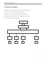
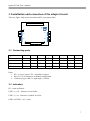
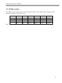
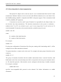
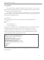
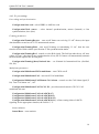
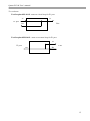
Multi-Channel interface boards
Quasar-8PCI-PC104
Quasar-4PCI-PC104
User’s manual
Version 1.0
11.11.2014
Novosibirsk 2007-2014
Quasar-PC104 User’s manual
Developer and manufacturer: Parabel Ltd.
630090, Novosibirsk-90, P.O.Box 126
http://www.parabel.ru
Email: [email protected]
Phone/Fax: +7-383-2138707
2
Quasar-PC104 User’s manual
Attention! It is not recommended to use this product on physical lines
without lightning protectors and going outside one building.
3
Quasar-PC104 User’s manual
Contents
1. INTRODUCTION ........................................................................................................... 5
2. DESIGN OF THE ADAPTER .......................................................................................... 6
3. INSTALLATION AND CONNECTION OF THE ADAPTER BOARD ............................ 7
3.1. Connecting ports........................................................................................................................................................ 7
3.1. Indication ................................................................................................................................................................... 7
3.2. PC104+ switch ........................................................................................................................................................... 8
4. SOFTWARE ................................................................................................................... 9
4.1. Introduction ............................................................................................................................................................... 9
4.3. Driver installation.................................................................................................................................................... 10
4.4. Configuration of E1 ports ....................................................................................................................................... 11
4.5. Select timeslots for data transmission .................................................................................................................... 12
4.6. ecfg utility ................................................................................................................................................................. 13
5. ADAPTER TECHNICAL SPECIFICATIONS ............................................................... 16
6. DELIVERY SET ........................................................................................................... 16
7. USEFUL LINKS ............................................................................................................ 16
4
Quasar-PC104 User’s manual
1. Introduction
Quasar interface board (hereinafter referred to as adapter) is intended for connection of E1
interfaces to the servers running under Asterisk soft PBX. The adapter is configured as a computer
board of PC104+ format. The adapter is controlled by a special driver developed for the Linux OS.
The Quasar adapter possesses the following features:
•
Quantity of E1 channels used: 4 or 8
•
Total access embedded hardware timeslots switcher with 256x256 channels matrix
•
DMA mode for data transfer to PC without CPU
•
Automatic selection of the synchronization channel
•
Autmatic E1 sensitivity adjustment of the receiver (up to -40dB) for 0 port
•
PCI 3V or 5V
Adapter hardware versions are given in the following table.
Quasar-8PCI-PC104
Quasar-4PCI-PC104
Quasar-8PCI-PC104-5
Quasar-4PCI-PC104-5
8 E1 ports
4 E1 ports
8 E1 ports, extended temperature
4 E1 порта, extended temperature
5
Quasar-PC104 User’s manual
2. Design of the adapter
The adapter consists of the following functional units (see the figure below):
LIU & Framer – G.703 transceiver chip and G704 framer
TDM switch – E1 timeslots cross connector (256x256 timeslots)
DMA controller enables data transfer between the adapter and PCI bus
PCI bridge – bridge chip for PCI/PCIe bus
PCI
Bridge
DMA controller
TDM switch
LIU &
Framer
E1
LIU &
Framer
E1
LIU &
Framer
E1
LIU &
Framer
E1
6
Quasar-PC104 User’s manual
3. Installation and connection of the adapter board
There are figure with sockets locations and E1 ports pinout table.
X6
X9
A0
A1
D1
X2
X3
X1
X4
X7
3.1. Connecting ports
Signal\Port
TX+
Port 1
X1.1
Port 2
X1.7
Port 3
X2.1
Port 4
X2.7
Port 5
X3.1
Port 6
X3.7
Port 7
X4.1
Port 8
X4.7
TXRX+
X1.2
X1.3
X1.8
X1.9
X2.2
X2.3
X2.8
X2.9
X3.2
X3.3
X3.8
X3.9
X4.2
X4.3
X4.8
X4.9
RX-
X1.4
X1.10
X2.4
X2.10
X3.4
X3.10
X4.4
X4.10
Notes.
1. RX – receiver (input), TX – transmitter (output)
2. Ports 5,6,7,8 are absent for 4-channel configuration
3. Connectors type is IDC-10 right angle, 2.54 mm.
3.1. Indication
D1 – mode indicators
LED 1,2 = off - firmware is not loaded
LED 1,2 = on – firmware is loaded, no driver
LED1=on LED2 = off – ready
7
Quasar-PC104 User’s manual
3.2. PC104+ switch
The adapter can be located in one of four positions in the PC-104+ address space. Jumpers A0, A1
define PCI signals to be used for work.
Slot
A1
1
On
2
Off
3
On
4
Off
Note. On – jumper installed.
A0
On
On
Off
Off
CLK
CLK0
CLK1
CLK2
CLK3
REQ
REQ0
REQ1
REQ2
REQ3
GNT
GNT0
GNT1
GNT2
GNT3
IDSEL
IDSEL0
IDSEL1
IDSEL2
IDSEL3
8
Quasar-PC104 User’s manual
4. Software
4.1. Introduction
The adapter operation depends on the following software components:
1. DAHDI package (earlier - Zaptel). This component provides low-level procedures with
telephone equipment. Supply of the DAHDI package with the adapter is not obligatory, so
the download from the public Internet resources is acceptable (see “Useful links” at the end
of the Manual). The compatibility with the original DAHDI package is guaranteed, no
patches needed.
2. Quasar.ko driver. It is a logical part of the DAHDI package. This component provides
adapter specific functions. The driver is supplied in the source code presentation. The driver
must be compiled before loading into a system. The corresponding software should be
available on the server to do it.
3. The /etc/dahdi/system.conf configuration file. Parameters of the E1 ports and selected
timeslots are specified in the file. The file is modified by a user with the help of any text
editor installed in the system. Configuration file syntax is out of scope of this document.
Nevertheless, the commands relative to the adapter configuration are presented here.
4. The dahdi_cfg configuration utility. The utility based on the configuration file transmits
some parameters to the driver. After any changes in the configuration file, the utility should
be restarted.
9
Quasar-PC104 User’s manual
4.2. System requirements
Before the driver installation the following software must be installed in the system:
•
binutils, make and gcc compiler
•
Kernel header files
•
DAHDI package in source codes
Learn DAHDI and Asterisk documentation before installation and operation of the driver.
4.3. Driver installation
The driver is packed in the /Quasar/driver/quasar-x.x.x.tar.bz2 tar archive located on the CD
included into the delivery set. Drivers of the 3.0.0 version and later work with the DAHDI package.
As every version has its own requirements for driver installation, a user should strictly follow the
instructions of README file packed in the same archive.
The final step of the driver compilation is loading quasar.ko module on a system. Before
loading it in the system, please ensure the adapter is successfully recognized by the Linux PCI
subsystem. To check it, run the lspci utility. After utility start the list of PCI devices will appear on
the screen. The following device must be in the list:
Network controller: Altera Corporation Device
If the system recognizes the adapter, then the driver will be successfully loaded. The list of the
loaded modules (lsmod utility) confirms the successful load. The quasar module must be presented
in the list. The module as well reports on successful load in the /var/log/messages log.
10
Quasar-PC104 User’s manual
4.4. Configuration of E1 ports
E1 ports of the adapter are described in the /etc/dahdi/system.conf configuration file. The span
key word defines parameters of the given port.
span = <span_num>,<timing>,<LBO>,< framing>,<coding>[,crc4]
where
span_num – E1 port number (from 1 to the maximum port number in the board)
timing – should the port be used as a synchronization source
0 – port is E1 master
1 and more – E1 slave port. The port is among the adapter synchronizing sources.
The greater the number, the less the port priority is.
LBO – ignored parameter, set 0.
Framing – telephony signaling, acceptable values are ccs, cas.
Coding – line coding, acceptable values are ami or hdb3
Crc4 – allow crc4 verification and generation (an optional parameter)
11
Quasar-PC104 User’s manual
4.5. Select timeslots for data transmission
The Quasar-E1 adapter can be used not only for voice-communication link, but for E1 data
transmission. Both the functions can be exercised with different channels, but on one board. Note,
the DAHDI package should be compiled with HDLC subsystem support. This is determined with
CONFIG_DAHDI_NET parameter.
31 timeslots are used for each E1 port (Timeslot 0 is responsible for the frame format, it is
not involved into data transmission). The timeslots enumeration in the system is continuous –
numbers from T1 to T31 are referred to port 1, port 2 covers range from 32 to 62, and so on. To
switch demanded E1 timeslots to the network interface, nethdlc keyword is used:
nethdlc=<S>-<E>
where
S – number of the initial timeslot,
E – number of the final timeslot
For example.
nethdlc=2-13
For the given configuration 12 timeslots of the first port, starting with 2 and ending with 13, will be
configured as one data transmission channel.
To register timeslots, a comma can be also used. For example, the same group of timeslots can be
written as:
nethdlc=2,3-13
The group of timeslots described with the nethdlc enumeration forms a network interface with
hdlc0 name in the Linux network subsystem. hdlc1 corresponds to the next given command, and so
on. The data link protocol of this interface can be configured with the help of sethdlc command.
For example, command
sethdlc hdlc0 cisco
specifies cisco-compatible hdlc protocol on the channel. For further information see sethdlc
documents.
12
Quasar-PC104 User’s manual
4.6. ecfg utility
The ecfg utility allows adjustment of parameters of the E1 interfaces. It can be used as a
simple E1 analyzer. The ecfg program can be used for configuration of some parameters which are
not subject to the DAHDI configuration utilities.
The utility uses a /dev/quasar special file for interfacing the driver. The prevous paramters
adjusted by DAHDI are easily overridden with the utility. The utility runs independently and does
not update data in the DAHDI structures.
4.6.1. Main menu
The ecfg utility is launched in the Linux command string with the following parameters:
# ecfg -b M –i N
Where,
M – board number [0,1, …]
N – E1 port number, 0 or 1
E1 parameters are configured by means of modifying the parameters in hierarchical menus. When
configuration completed, the settings can be kept in a file. Configuration is saved in the
/etc/ecfg/quasarM_N.cfg file, where M and N – numbers of the board and port. When ecfg is
launched, the main menu will be displayed on the screen containing information on software
version, board and port numbers, status of the given E1 port.
Quasar monitor v.1.14 26/08/2008 Updates: http://parabel.ru/
PMC/chan=0/0, conf. file="/etc/emcfg/quasarm0_0.cfg"
HW/FW/REV version=10/10/e, driver verision=2.0.3
Line status: LOS=On , AIS=Off
Frame status: LOF=On , Sa4..8=00000, RAIS=Off
CAS Multiframe: CAS LOM=Off, XYXX=0000
CRC4 Multiframe: CRC4 err=Off, LOC=On , E bit=On
Err counters: HDB3=0, FAS=0, CRC4=0
ABCD status: 00000000 00000000 00000000 00000000
1. Configuration >>
2. Status >>
3. Test >>
0. Quit
Press 1-9 keys to select submenu, or press 0 to exit the submenu. Other keys can be used to refresh
status information.
13
Quasar-PC104 User’s manual
4.6.2. E1 port settings
Line coding and synchronization
Configuration/Line code - select HDB3 or AMI line code
Configuration/Clock source – select internal synchronization, master (Internal) or line
synchronization, slave (line)
Framing parameters
Configuration/Framing/Receive – turn on/off framer on receiving. If “off” chosen, the input
data should be treated as raw G.703 unstructured stream.
Configuration/Framing/Xmit - turn on/off framing on transmitting. If “on”, then the zero
timeslot will be filled with the specification G.704 synchronization marks.
Configuration/Framing/RAI - control over the RAI signal. The field can take the on, off, auto
values. If “auto”, then basic frame synchronization is lost, the E1 framer will automatically transmit
the RAI alarm signal to the far-end point.
Configuration/Framing/(Inter)National bits – set National & International bits (Sa4-Sa8,
Si0, Si1)
Multiframe parameters
Configuration/Multiframe/CRC4 multiframe – turn CRC4 on/off
Configuration/Multiframe/CAS – turn on/off CAS multiframe
Configuration/Multiframe/CAS/Remote CAS Alarm – control over the CAS alarm signal (Y
bit). Turn CAS alarm “on”, “off”
Configuration/Multiframe/CAS/X1, X2, X3 – provides manual control of X1-X3 CAS
multiframe bit state
Configuration/Multiframe/CAS/ts16 ABCD(1-7)
Configuration/Multiframe/CAS/ts16 ABCD(8-15)
Configuration/Multiframe/CAS/ts16 ABCD(16-23)
Configuration/Multiframe/CAS/ts16 ABCD(24-31) – allows setting 4 bits of ABCD
signaling for the appropriate timeslot, the field is 0 .. F.
Status submenu
Status/Reset – reset statistics
14
Quasar-PC104 User’s manual
Test submenu
Test/Loopback/LLOOP - turns on a local loop for E1 port
Tx
Tx
E1 port
Line
Rx
Test/Loopback/RLOOP – turns on a remote loop for E1 port
Tx
E1 port
Line
Rx
Rx
15
Quasar-PC104 User’s manual
5. Adapter technical specifications
Parameter
Connector type
Cable type
Nominal pulse voltage
Data transmission rate
Coding
Signal attenuation, no more than
Conformance to standards
Pulse form
Range of phase jitter
Frame structure
Control
Dimensions
Ambient conditions, normal
Ambient conditions, extended
Description
IDC right angle, 10 pins
symmetrical twisted pair, 120 ohm
3 V +- 10%
2048 kbit/s +- 50 ppm
AMI/HDB3
-40 db for port 1, -6 db for ports 2..8
ITU-T G.703, G.704, G.706, G.732, G.823
ITU G.703
ITU G.823
ITU G.704
PCI 3v or 5v
90 x 96 x 23 mm
T from +5 to +50° С
T from -40 to +70° С
6. Delivery set
• Adapter board
• CD with driver and user’s manual
• Guarantee card
• Package box, dimensions: 26x17x3 cm
Weight is less than 0.5 kg.
7. Useful links
http://www.asterisk.org/downloads
16
Versions.
1.0 – based on 1.4.1 Quasar-E1