1
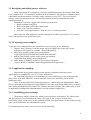
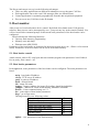
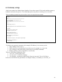
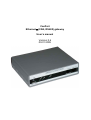
CanPort
EthernetÙ(CAN, RS485) gateway
User’s manual
Version 0.6
09.01.2005
© PARABEL, ltd
ALL RIGHTS RESERVED
CANPORT GATEWAY USER’S MANUAL
RELEASE 0.6, SEPTEMBER 2005
PARABEL LIMITED
P.O. BOX 126
NOVOSIBIRSK-90
RUSSIAN FEDERATION
Web: www.parabel-labs.com
Email: [email protected]
Phone: +7-383 2138707
Fax: +7-913 9139603
2
CONTENTS
1. Introduction..................................................................................................................................4
2. Hardware description...................................................................................................................5
2.1. CPU module..........................................................................................................................5
2.2. Network interfaces................................................................................................................5
3. Software.......................................................................................................................................5
3.1 Developing embedded gateway software ..............................................................................6
3.1.1 Preparing cross-compiler ................................................................................................6
3.1.2 Application compiling ....................................................................................................6
3.1.3 Assembling gateway image ............................................................................................6
3.1.4 NFS file system usage ....................................................................................................7
3.2 Using CAN gateway server ...................................................................................................7
5. Boot monitor................................................................................................................................8
5.1. Boot loader console ..............................................................................................................8
5.2. Boot loader parameters .........................................................................................................8
5.3. Boot loader service commands .............................................................................................9
5.4. Upgrading CAN gateway firmware......................................................................................9
6. Gateway setup............................................................................................................................10
7. Gateway delivery .......................................................................................................................11
8. Package ......................................................................................................................................11
Appendix 1. Technical data ...........................................................................................................12
Appendix 2. Sockets pinout...........................................................................................................13
Appendix 3. CAN bus monitor application ...................................................................................14
Appendix 4. SDK directories description......................................................................................15
3
1. Introduction
The field buses, like CAN or PROFIBUS are wide used in the industrial control systems.
Office PC with appropriate interface card is often used as bus controller in such systems. It is
convenient solution, which is not quite optimal:
1. There are difficulties in the geographical separation of terminals and controllers (CAN
cable length is not more than 1000 m)
2. PC has high power consumption
3. There are many unreliable elements of mechanics in PC (hard drive, fan)
4. The large dimensions of PC box
5. The cost of PC with interface card is relatively high
6. The narrow ambient temperatures range
7. Problems with access of multiple users to one CAN line
The offered device (CanPort) is gateway between telemetric buses (CAN, RS485) and data
transmission networks (Ethernet, RS232). GPRS modem can be used for data connection as well.
GPRS connectivity can significantly speed up the target system installation in conditions of poor
telecom infrastructure.
Gateway is powered by FreeScale RISC processor MPC852 with approximately 48 MIPS.
There are 32 megabytes of SDRAM memory and 4 megabytes of flash with the data compression
capability. Linux with kernel 2.4 is used as embedded operating system.
There are two alternative application schemes of the gateway. The first is remote CAN
interface. The second is programmable logical controller (PLC).
In the first case gateway acts as TCP server and retransmits packets between IP net and
CAN line. Client is any workstation in the IP net. Client software resides in the workstation and
connects to the server with help of CAN library. Library shadows the client – server exchange
complexity from user. So, application software works with library calls like with local CAN
interface.
Some times it is not practical to transport all data from sensors. It is more convenient to
process sensors information in the CAN gateway. There is possibility to develop C and C++
programs for the embedded gateway system. Some known SCADA systems can be easily adopted
for gateway, for example EPICS (see http://www.aps.anl.gov/epics/).
CanPort gateway is completed with:
• developer SDK (with cross compiler GCC 3.2, pthread, …)
• Client library for Linux, Windows
• Portable CAN monitor software, which can be used for debugging CAN exchange and
messages transmission
4
The offered application scheme:
2. Hardware description
2.1. CPU module
Gateway is powered by FreeScale RISC processor MPC852 with approximately 48 MIPS.
There are 32 megabytes of SDRAM memory and 4 megabytes of flash with the data compression
capability.
2.2. Network interfaces
Ethernet interface is used for local area network attaching and it has RJ45 socket on the rear
gateway panel. RS232 port can be used for low speed data transmission, for example with help of
GPRS modem, dial-up modem or DSL.
Sensors network can be attached to two CAN interfaces (CAN version 2.0b) and one RS485
port. CAN ports are serviced by SJA1000 controllers with data rate up to 1 Mbit/s.
3. Software
Embedded software of CanPort is based on Linux kernel 2.4.x and set of utilities. The two
variants of gateway usage are following:
1. Software platform and programmable logical controller
The application programs are loaded and activated in the gateway. CAN ports can be
accessed through CAN interface driver by means of /dev/canXX special devices.
2. Gateway between CAN lines and data transmission networks. In this variant the device
function like remote CAN interface.
Note: RS485 and RS232 interfaces are not supported in the current software release of CanPort.
There are following features of the CanPort embedded software:
• Linux 2.4
• CAN server
• CAN driver (read, write, select, ioctl)
• Telnet server and client
• FTP server
• PPP daemon
• Rdate (time synchronization with help of NTP protocol)
5
3.1 Developing embedded gateway software
Linux (x86) based PC workstation is used for embedded programs developing. SDK with
cross-compiler GCC 3.2.2 should be installed on the workstation. The gateway is completed with
embedded Linux kernel and set of utilities, made with help of cross GCC. The set of internal
utilities is based on busybox project. All internal programs should be compiled with math
emulation turned on.
Embedded CAN driver supports the following system calls:
1. Read (read data from FIFO)
2. Write (write data to FIFO for transmission)
3. Select (wait CAN line readiness)
4. ioctl (set CAN chip parameters - filter for receive, bit timing, status)
Driver interacts with application software through /dev/canXX special files. User can also
read CAN statistics in the /procfs filesystem.
3.1.1 Preparing cross-compiler
To prepare cross compilation on the workstation it is necessary to do the following:
1. Unpack ‘linux’ directory from file cangw-x86-cross-sdkXX.tgz to any place on the
workstation file system (as example - /home/sdk/ppc860/).
2. Add path to compiler to the system environment
”export PATH=$PATH:$PPC860_BASE/linux/tools/bin/”
3. Add PPC860_BASE variable to the system environment
”export PPC860_BASE=/home/sdk/ppc860”
4. Add CROSS_COMPILE variable to the system environment
“export CROSS_COMPILE=/home/sdk/ppc860/tools/bin/ppc-linux-“
3.1.2 Application compiling
Applications are programs running on the gateway embedded operating system.
Applications are compiled by cross GCC on the workstation.
For compiling programs it is recommended to create subdirectory in the /linux/apps and
place source texts here. Makefile, created with GNU make rules, should be placed in this
subdirectory also.
There are helpful files in the linux/apps directory – Makeconfig and Makemodules. Both
files are intended for including to the main Makefile (see linux/apps/sample/Makefile for example),
and contain path definitions for header files, libraries and other auxiliary files. Makeconfig is used
in applications building rules. Makemodules is used in module building rules.
3.1.3 Assembling gateway image
The gateway image is binary file, which is prepared on the workstation. The Linux kernel
and file system tree are included to the image. The copy of file system is located in the
linux/initrd_cangw subdirectory on the workstation SDK. User applications, created in the previous
stage, can be included to the embedded file system.
To assembly gateway image it is necessary to do the following:
6
1. Create file system image with help of mkramdisk script. The command line parameter of
this script is file system location in the workstation directory (i.e. linux/initrd_cangw).
2. Create boot image of gateway (file system + Linux kernel) with help of mkbootimage.
After preparing gateway boot image, it should be loaded to the device memory and
programmed to flash memory. The detailed instructions about flash programming are given in the
5.4.
Important! For successful booting Linux command line should be defined as:
“root=/dev/ram rw ramdisk_size=5000 init=/sbin/flash”
Command line is edited in the boot monitor parameters.
Warnings:
Scripts mkramdisk and mkbootimage should be executed with root access rights.
It is necessary to create /tftpboot directory on the workstation and to give access for tftp
server for it.
If application is frequently recompiled, it is practical to use NFS file system as root and only
load kernel to the gateway.
3.1.4 NFS file system usage
NFS usage can simplify application development (without reloading new image). The
command string of the boot monitor should contain:
“root=/dev/nfs rw nfsroot=192.168.1.1:/home/sdk/ppc860/linux/initrd
ip=192.168.1.2:192.168.1.1::255.255.255.0::eth0:off”,
where,
192.168.1.1 – NFS server address, 192.168.1.2 – IP gateway address.
This command string is analyzed by gateway software while system starting. The gateway root file
system is taken from the remote server – workstation with Linux. It is necessary to export NFS
directory on the workstation. To do this, add the following string
“/home/sdk/ppc860/linux/initrd_cangw 192.168.1.2(rw,no_root_squash,sync)”
to the file /etc/exports on the workstation. Then restart NFS server.
3.2 Using CAN gateway server
Application software can be developed on the remote host. One of the following platforms
can be used for this:
• Linux, x86
• Linux, PPC
• Windows, x86 (Using MSVC 6.0 & GCC)
Access to the CAN lines is accomplished through cangw-X.X.tar.bz2 library, included to SDK. The
library program interface is described in html format. The library connects to embedded TCP server
can4lgw, working in the gateway. The server redirects packets from IP network to CAN and vice
versa. The interface protocol between library and server is based on TCP and hidden from user. On
this reason handling remote CAN line is equivalent to handling local CAN adapter.
The library is written on C (without C++), use one thread, but can be used in the multi-threaded
applications. Library functions have timeout parameter and are not lock application for a long time.
The CAN monitor application (see code sources in SDK) is example of program, which exploit
remote CAN interface with help of gangw library. Monitor display ingress and egress CAN
packets, this is useful for debugging. The cangw library can be ported on any OS, supporting
Berkley sockets and POSIX threads.
7
The library and cangw server gives the following advantages:
• There are many applications on different workstations can use the same CAN line
• Each application can set the own CAN messages filter (to offload IP net)
• Control application is separated geographically from the data acquisition equipment
• Easy access to any CAN lines in the IP domain
5. Boot monitor
After power on, boot loader takes device control. By default, boot loader starts CAN gateway
software. Boot process can be interrupted by user – just press any key in the console window. You
will see boot loader command prompt. In this mode some parameters of the boot loader can be
configured.
Boot loader has the following functions:
• Gateway flash memory programming
• Memory tests and dump
• Ethernet tests (ARP, PING)
Parameters of the boot loader are structured in the menu system (press <h>, <Enter> to list current
menu). Parameters of the boot loader can be saved in the flash memory.
5.1. Boot loader console
Attach console cable to PC serial port and start terminal program with parameters: baud 38400, 8
bit, no parity, flow control = off.
5.2. Boot loader parameters
In the opt menu, some parameters of the boot loader can be configured. The main parameters are
listed:
myip - boot loader IP address
servip - TFTP server IP address
gwip - в gateway IP address
mask - network mask
file - image file name
loadptr – memory address for image file loading, should be 0x200000
jumpptr – address for Linux kernel starting, should be 0x200000
bootstr – Linux command string, see 5.3.
list – print values of boot loader parameters
flags – go to flags menu
The flags must be set to following values:
verbose mode
off
standalone tftp server
on
enable auto load after startup
on
enable auto jump after startup
on
enable auto fflash after startup
off
copy vxstr to ram
off
watchdog timer
off
update – save parameters in the flash memory
8
5.3. Boot loader service commands
pings – go to ICMP echo server mode. You can ping CAN gateway from other network station.
bootp – execute BOOTP request
arp – resolve server IP address (send ARP request)
mdump – dump memory region
mfill – fill memory region
mtest – testing memory region
fflash – flash memory programming (file, myip, servip, mask, gwip must be configured first).
Other commands are intended for factory testing.
5.4. Upgrading CAN gateway firmware
To write the new software release:
• Start TFTP server program on PC and enable read access to some folder in the PC filesystem.
• Copy to this folder image.bin file with CanPort software image
• Attach console and Ethernet cables to CanPort
• Start terminal program on PC and set com port parameters: 34800, 8 bit, 1 stop, no parity.
• Restart CanPort (reboot command).
• Stop boot process (press any key in the terminal). After that, device is in the boot loader mode.
• If needed, change boot loader IP address and net mask (opt menu of boot loader).
• Programming starts with fflash command:
boot> fflash<CR>
9
6. Gateway setup
After boot monitor has finished kernel loading, Linux takes control. The kernel initializes gateway
hardware and starts init process. The following system setup flows according /etc/rc.sh script.
This screenshot presents boot process after /etc/rc.sh script has been started.
#!/bin/sh
echo " "
echo "*************************************"
echo "CAN gateway linux image Ver. 1.05"
cat /etc/image.date
echo "*************************************"
echo " "
/sbin/ifconfig lo 127.0.0.1
/sbin/ifconfig eth0 192.168.3.160 netmask 255.255.255.0
>/etc/mtab
# mount /proc so "reboot" works
/bin/mount -t proc proc /proc
echo "Loading CAN driver..."
insmod /lib/modules/2.4.22/Can.o
echo "Configuring CAN interfaces..."
/etc/cansetup
/usr/sbin/xinetd -stayalive -reuse -pidfile /tmp/xinetd.pid
echo "Starting CAN gateway..."
/usr/bin/can4lgw
To change some gateway parameter (for example, IP address), it is necessary to do:
1. Stop can4lgw server (ctrl-c)
2. Edit script /etc/rc.sh with help of text editor joe (for example, joe /etc/rc.sh)
3. Save settings to the flash memory with usage of writeflash command
4. Reboot gateway (reboot command or reset switch).
There are following configuration files:
1. /etc/rc.sh – system setup script
2. /etc/can.conf – CAN driver settings
3. /etc/cansetup – parameters path scenario from /etc/can.conf file to CAN driver
In the can.conf file the only parameters are changed: Baud_N, AccMask_N, AccCode_N.
10
7. Gateway delivery
Multiplexer is shipped with the following accessories:
• Gateway – 1
• Console cable (RJ11-DB9) – 1
• CD disk with documentation – 1
The following accessories can be shipped separately:
• Power source AC 220V
8. Package
Multiplexer is packaged to the carton box with dimensions 26x21x6.5 cm.
11
Appendix 1. Technical data
CPU
PowerPC 50 MHz RISC
Memory
32 Mbytes SDRAM
Flash
4 Mbytes Flash with compression
OS
Linux 2.4
Console
RS232, 34800, 8 bit, 1s, np
Net
interfaces
Ethernet 10/100, RJ45
CAN0
Can 2.0b, Isolated, D-SUB-9m
CAN1
Can 2.0b, Isolated, D-SUB-9m
RS485
Isolated, RJ45
RS232
D-SUB-9m, DTE
Ambient
temperature
0-60 °С
Dimensions
140x110x40 mm
Power
External power source, 220v ± 20%, 5w
12
Appendix 2. Sockets pinout
Ethernet (X2)
Pin Net
1 TX+
2 TX3 RX+
4
5
6 RX7
8
Console(X1)
Pin Net
Direction
1
RXD input
2
TXD output
3
GND
4
GND
5
6
CAN (X6 – CAN0, X7 – CAN1)
pin net
1 balance resistor 1
2 CanL
3 CAN shield
4 balance resistor 2
5 Device ground
6 Power output 0 V
7 CanH
8 NC
9 Power output 5 V
Notes:
1. Internal balance resistor (120 ohm) can be switched on by jumper (inside gateway box,
near CAN socket) or by connecting pins 1 and 4 of CAN socket.
2. Pins 6 and 9 can be used for isolated powering of external device with consumption less
then 100 ma.
RS485 socket (X8)
Pin Net
1
2
3
DATA_A
4
DATA_B
5
6
-
13
RS232 socket, DTE (X4)
Pin Signal Direction
1 CD
input
2 RXD input
3 TXD output
4 DTR output
5 GND ground
6 7 RTS
output
8 CTS
input
9 RI
input
Power socket (X3)
The central contact is +12..+24 V, side contact is ground
Indication
HL1 – power
HL2 – Link/ACT Ethernet
Appendix 3. CAN bus monitor application
14
Appendix 4. SDK directories description
linux/ - cross-SDK
apps/ – make scripts examples
initrd/ – link to the gateway root directory (for NFS booting)
initrd_big/ - target PowerPC applications, utilities and header files
Includes GCC, top, nice, perl, awk, bash, apache, etc.
Can be used for coping to the original distributive.
initrd_cangw/ - gateway root directory
kernel/ - link to Linux kernel directory
tools/ - cross tools (host – x86, target – PowerPC)
tools_host/ - utilities
15