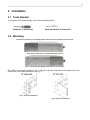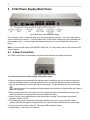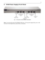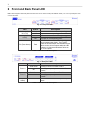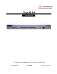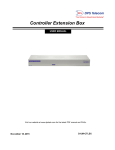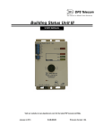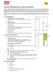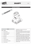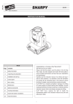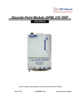
1
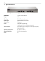
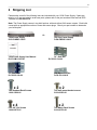
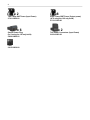
12/24 Power Supply G2
USER MANUAL
Visit our website at www.dpstele.com for the latest PDF manual and FAQs.
March 3, 2011
D-OC-UM113.03100
Revision History
March 3, 2011
Updated manual to reflect new design and build options
December 16, 2009
User Manual released. (D-OC-UM09C.16100)
This document contains proprietary information which is protected by copyright. All rights are reserved. No part of this
document may be photocopied without prior written consent of DPS Telecom.
All software and manuals are copyrighted by DPS Telecom. Said software and manuals may not be reproduced, copied,
transmitted or used to make a derivative work, by either mechanical, electronic or any other means in whole or in part,
without prior written consent from DPS Telecom, except as required by United States copyright laws.
© 2011 DPS Telecom
Notice
The material in this manual is for information purposes and is subject to change without notice. DPS Telecom shall not be
liable for errors contained herein or consequential damages in connection with the furnishing, performance, or use of this
manual.
1
1 Specifications
Fig. 1 - Use 12/24 Power Supply to distribute power to all your external sensors.
Dimensions:
1.7" H x 17.0" W x 4.34" D
Weight:
2.5 lbs.
Mounting:
19" or 23" rack or wall mount
Power Input:
-48VDC Normal (-36 to 72VDC)
Current Draw:
5 Amps max
Fuses:
5 Amp GMT for power input
1 Amp for each +12 or +24V power output pair
Visual Interface:
8 Front Panel LEDs (4 if using the 12 Volt output only build)
3 Back Panel LEDs
Operating Temperature:
32°–140° F (0°–60° C)
Operating Humidity:
0%–95% non-condensing
RoHS:
5/6
2
2 Shipping List
Please make sure all of the following items are included with your 12/24 Power Supply. If parts are
missing, or if you ever need to order new parts, please refer to the part numbers listed and call DPS
Telecom at 1-800-622-3314.
Note: The Power Supply comes in two build options: with and without 24V sensor outputs. Each build
comes with an appropriate number of fuses and sensor plugs. Check your part number to determine
your build option.
Or
12/24 Power Supply
D-PK-PWRSP-12005
12/24 Power Supply User Manual
D-OC-UM113.03100
23" Rack Ear
D-CS-325-10A-00
x2
Two Standard Rack Screws
1-000-12500-06
x4
Four 3/8" Ear Screws
1-000-60375-05
12V Only Power Supply
D-PK-PWRSP-12004
19" Rack Ear
D-CS-325-10A-00
Wall Mount Bracket
D-CS-532-10A-05
x2
Two wall mount bracket screws
2-000-60250-01
x2
Two Metric Rack Screws
2-000-80750-03
3
x2
Two 5-Amp GMT fuses (Input Power)
2-741-05000-00
x6
Sensor Power Plug
(3x if using the 12V only build)
2-820-00862-02
Pads
2-015-00030-00
x8
Eight 1-Amp GMT Fuses (Output power)
(4x if using the 12V only build)
2-741-01000-00
x2
Two Power Connectors (Input Power)
2-820-00862-02
4
3 Installation
3.1 Tools Needed
To install the 12/24 Power Supply, you'll need the following tools:
Phillips No. 2 Screwdriver
Small Standard No. 2 Screwdriver
3.2 Mounting
Flush mount - Rack ears are installed @ front of the unit, with front panel flush to the rack
Rack mount - Rack ears are installed @ back of the unit
Fig. 2 - The 12/24 Power Supply can be flush or rear-mounted
The 12/24 Power Supply mounts in a 19" or 23" rack, and can be mounted on the right or left, in the
flush-mount or rear mount locations (see Fig. 2)
Fig. 3 - Rack ear dimensions
Fig. 4 - Rack ear dimensions
5
4 12/24 Power Supply Back Panel
Fig. 5 - Back panel of the 12/24 Power Supply.
The fuse alarm relay is a normally open relay that closes when a fuse fails. You can use the relay to
report a fuse failure to an RTU. (Some models of the 12/24V Power Supply don't come standard with
the fuse alarm relay. Your build option will determine whether or not your model has a fuse alarm
relay.)
Note: If you have build option D-PK-PWRSP-12004 (the +12V only build), your unit will not have +24V
sensor outputs.
4.1 Power Connection
The 12/24 Power Supply is powered by two screw terminal barrier plug power connectors.
Fig. 6 - Screw terminal barrier plugs
To connect the unit to a power supply, follow these steps:
1. Always use safe power practices when making power connections. Be sure to remove fuses from
the fuse distribution panel, as well as the back of the unit, before making your power connections.
2. Use the grounding lug to connect the unit to earth ground. The grounding lug is next to the symbol
. Insert the eyelet of the earth ground cable between the two bolts on the grounding lug (Ground
cable not included).
3. Insert a battery ground into the power connector plug's right terminal and tighten the screw; then
insert a battery line to the plug's left terminal and tighten its screw.
4. Insert a fuse into the fuse distribution panel and measure voltage. The voltmeter should read
between –36 and –70VDC.
5. The power plug can be inserted into the power connector only one way to ensure the correct
polarity. Note that the negative voltage terminal is on the left and the GND terminal is on the right.
6. Insert fuse into the Power A fuse slot. The power LED should be lit green.
7. Repeat steps 1 -6 for Power B connector.
6
5 12/24 Power Supply Front Panel
Fig. 7 - Front panel connections for the 12/24V Model
Note: If you have build option D-PK-PWRSP-12004 (the +12V only power supply build), your unit will
not have +24 Volt Output fuses, sensor LEDs, or fuse alarm.
7
6 Front and Back Panel LED
Note: These DIagrams reflect LED placement and function for the 12/24V model (D-PK-PWRSP-12005). The +12V only build option does
not have 24V LEDs.
Fig. 8 - Front panel LEDs
LED
Status
Description
24 Volt (1/2,
3/4 or 5/6)
Green
Off
Green
Power is available on the corresponding ports.
No power on corresponding ports.
Power is available on the corresponding ports.
12 Volt (1/2, 3/4,
or 5/6)
FA (Fuse Alarm)
Off
No power on corresponding ports.
Red
Fuse Failure on one of the corresponding
sensor output power feeds. The FA LED
under the 24 Volt Output area indicates a fuse
failure on the +24 volt outputs while the LED
under the 12 Volt area indicates a failure on
the +12V outputs.
Table 1 - Back Panel LED Descriptions
Fig. 9 - Back panel LEDs
LED
Status
Solid Green
Power A
Power B
FA (Fuse
Alarm)
Off
Solid Green
Off
Red
Description
Polarity is correct on Power Feed A.
No voltage, or polarity is reversed on Power
Feed A.
Polarity is correct on Power Feed B.
No voltage, or polarity is reversed on Power
Feed B.
Fuse Failure on one of the unit power input
feeds.
Table 2 - Back Panel LED Descriptions
8
7 Technical Support
DPS Telecom products are backed by our courteous, friendly Technical Support representatives, who
will give you the best in fast and accurate customer service. To help us help you better, please take
the following steps before calling Technical Support:
1. Check the DPS Telecom website.
You will find answers to many common questions on the DPS Telecom website, at
http://www.dpstele.com/support/. Look here first for a fast solution to your problem.
2. Prepare relevant information.
Having important information about your DPS Telecom product in hand when you call will greatly
reduce the time it takes to answer your questions. If you do not have all of the information when you
call, our Technical Support representatives can assist you in gathering it. Please write the
information down for easy access. Please have your user manual and hardware serial number ready.
3. Have access to troubled equipment.
Please be at or near your equipment when you call DPS Telecom Technical Support. This will help
us solve your problem more efficiently.
4. Call during Customer Support hours.
Customer support hours are Monday through Friday, from 7 A.M. to 6 P.M., Pacific time. The DPS
Telecom Technical Support phone number is (559) 454-1600.
Emergency Assistance: Emergency assistance is available 24 hours a day, 7 days a week. For
emergency assistance after hours, allow the phone to ring until it is answered with a paging message.
You will be asked to enter your phone number. An on-call technical support representative will return
your call as soon as possible.
9
8 End User License Agreement
All Software and firmware used in, for, or in connection with the Product, parts, subsystems, or derivatives thereof,
in whatever form, including, without limitation, source code, object code and microcode, including any computer
programs and any documentation relating to or describing such Software is furnished to the End User only under
a non-exclusive perpetual license solely for End User's use with the Product.
The Software may not be copied or modified, in whole or in part, for any purpose whatsoever. The Software may
not be reverse engineered, compiled, or disassembled. No title to or ownership of the Software or any of its parts
is transferred to the End User. Title to all patents, copyrights, trade secrets, and any other applicable rights shall
remain with the DPS Telecom.
DPS Telecom's warranty and limitation on its liability for the Software is as described in the warranty information
provided to End User in the Product Manual.
End User shall indemnify DPS Telecom and hold it harmless for and against any and all claims, damages, losses,
costs, expenses, obligations, liabilities, fees and costs and all amounts paid in settlement of any claim, action or
suit which may be asserted against DPS Telecom which arise out of or are related to the non-fulfillment of any
covenant or obligation of End User in connection with this Agreement.
This Agreement shall be construed and enforced in accordance with the laws of the State of California, without
regard to choice of law principles and excluding the provisions of the UN Convention on Contracts for the
International Sale of Goods. Any dispute arising out of the Agreement shall be commenced and maintained only in
Fresno County, California. In the event suit is brought or an attorney is retained by any party to this Agreement to
seek interpretation or construction of any term or provision of this Agreement, to enforce the terms of this
Agreement, to collect any money due, or to obtain any money damages or equitable relief for breach, the
prevailing party shall be entitled to recover, in addition to any other available remedy, reimbursement for
reasonable attorneys' fees, court costs, costs of investigation, and other related expenses.
10
11
“Dependable, Powerful Solutions
that allow users to monitor larger,
more complicated networks with a
smaller, less trained staff”
“Your Partners in Network Alarm Management”
www.dpstelecom.com
4955 E Yale • Fresno, CA 93727
559-454-1600 • 800-622-3314 • 559-454-1688 fax