1
ENDAT-3857 USERS MANUAL
UNICORN COMPUTER CORP.
ENDAT-3857
For ENDAT-3857 PCB ver. A3 or later
Document version: 4.2
Release Date: Oct.8.2015
1
ENDAT-3857 USERS MANUAL
UNICORN COMPUTER CORP.
Copyright Notice
The content of this manual has been checked for accuracy. The manufacturer
assumes no responsibility for any inaccuracies that may be contained in this
manual. The manufacturer reserves the right to make improvements or
modification to this document and/or the product at any time without prior
notice. No part of this document may be reproduced, transmitted, photocopied or
translated into any language, in any form or by any means, electronic, mechanical,
magnetic, optical or chemical, without the prior written permission of the
manufacturer.
Realtek is registered trademark of Realtek Technologies Inc.
Multiscan is a trademark of Sony Corp of America
IBM, EGA, VGA, PC/XT, PC/AT, OS/2 and PS/2 are registered trademarks of
International Business Machines Corporation
Intel® is a registered trademark of Intel Corporation
VIA is registered trademark of VIA Technology Incorporation
Plug and Play is registered trademarks of Intel Corporation
Microsoft, Windows and MS-DOS are trademarks of Microsoft Corporation
Award is a trademark of Phoenix Software Inc.
PCI is a registered trademark of PCI Special Interest Group
Other product names mentioned herein are used for identification purpose only and
may be trademarks and/or registered trademarks of their respective companies.
Installation Notice
The manufacturer recommends using a grounded plug to ensure proper
motherboard operation. Care should be used in proper conjunction with a
grounded power receptacle to avoid possible electrical shock. All integrated
circuits on this motherboard are sensitive to static electricity. To avoid
damaging components from electrostatic discharge, please do not remove
the board from the anti-static packing before discharging any static
electricity to your body, by wearing a wrist-grounding strap. The
manufacturer is not responsible for any damage to the motherboard due to
improper operation.
2
ENDAT-3857 USERS MANUAL
UNICORN COMPUTER CORP.
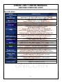
Specification:
Model
ENDAT-3857
SoC
Supporting
Intel® Atom™QC E3845 /2MB cache/1.91GHz / TDP=10W
Intel® Atom™ DC E3827 /1MB cache/1.75 GHz / TDP=8W
Intel® Atom™QC J1900 /2.0GHz Up to 2.4GHz /2MB cache / TDP=10W
Memory
BIOS
Ethernet
VGA
LVDS interface
DisplayPort
Dual view
Serial
RS 422 / 485
SATA
USB
Expansion
Watch Dog
Timer
AUDIO
Power Supply
Form Factor
1 x 204-Pin DDR3 SODIMM socket
support DDR3L-1333 up to 8 GB (Non-ECC)
Phoenix UEFI
2x Intel® 82583V PCI-E Gigabit LAN
Intel® Gen7 w/4EUs graphics engines
(@ 542MHz/792MHz [Turbo])
Supports DX 11, OGL 3.0, OCL 1.1, OGLES 2.0,
and Full HW acceleration, decode: H.264, MPEG2/4, VC-1,
WMV9. Encode: H.264, MPEG2
Shared memory ; Maximum resolution up to 1920 x 1200
24-bit dual channel via CH7511B through eDP
Support 18/24/36/48bit LVDS with backlight control
(maximum resolution 1920 x 1080 )
Video Display Port (Mini DP)
CRT + DP, CRT + LVDS, DP + LVDS
2 ports RS-232 with power selector (+12V / Ring-in / +5V)
by COM2
1 x SATA2 connector with AHCI support
USB 2.0 x 2 (1 external + 1 internal) & USB 3.0 x 1 (1 external)
2x Mini PCI-E (1 x full-sized, 1 x half-sized) Slot,
Half-sized support Mini PCIe or Mini or USB interface.
Full-sized support mSATA or Mini PCIe and USB interface.
On-chip supports 1 to 255 seconds / minutes
Intel® Atom™ SoC built-in HD Audio controller
Realtek HD Codec w/speaker 1.2W amplifier
9V~ 24V DC
102mm x 147mm (4“ x 5.8“)
3
ENDAT-3857 USERS MANUAL
UNICORN COMPUTER CORP.
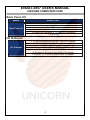
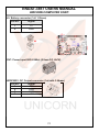
Back Panel I/O
Model
ENDAT-3857
Back Panel I/O
1 x PS2 Keyboard & Mouse Double-decker connector
1 x VGA
1 x Mini DP Display port
2 x RJ-45 Connector
1 x USB(2.0) Connector & 1 x USB(3.0) Connector
1 x SPK-out
I/O Onboard
I/O Onboard
1 x PS2 Keyboard & Mouse with 2.0mm Pin Header
COM1 & COM2 with 2.0 mm Box Header
1 x USB 2.0 with 2.54mm Pin Header
Speaker out, Line-in, CD-in, MIC-in, SPDIF with 2.0mm Pin Header
8-bits digital I/O for CMOS/TTL level
(4 bit input / 4 bit output) with 2.0mm Pin Header
1 x SPDIF + 1 x SM BUS with 2.0mm Pin Header
4
ENDAT-3857 USERS MANUAL
UNICORN COMPUTER CORP.
TABLE OF CONTENTS
CHAPTER 1. INTRODUCTION ...................................................... 6
1-1.
1-2.
1-3.
1-4.
FEATURES .............................................................................................. 7
UNPACKING ............................................................................................ 8
ELECTROSTATIC DISCHARGE PRECAUTIONS ................................... 8
MOTHERBOARD LAYOUT .................................................................... 10
CHAPTER 2. SETTING UP THE MOTHERBOARD..................... 11
2-1. Connector & Jumper List .........................................................................11
2-2. INSTALLING MEMORY.......................................................................... 23
2-3. SHARED VGA MEMORY ....................................................................... 23
2-4. WATCH DOG TIMER ..................................................................... 23 & 24
2-5. Digital I/O........................................................................................ 25 & 26
CHAPTER 3. Phoenix UEFIBIOS SETUP ................................... 27
CHAPTER 4. VGA, SDVO AND DRIVERS................................... 31
4-1. VGA FEATURE....................................................................................... 31
4-2. DRIVER UTILITY INSTALLATION GUIDE.............................................. 32
APPENDIX A: FLASH MEMORY UTILITY ................................... 33
APPENDIX B: LVDS PIN ASSIGNMENT ..................................... 34
APPENDIX C: CH7511B Backlight Control................................ 35
APPENDIX D: LIMITED WARRANTY .......................................... 36
5
ENDAT-3857 USERS MANUAL
UNICORN COMPUTER CORP.
Chapter 1. Introduction
In order to cope with the challenges of the system performance issues and demand
of much more visually embedded system in diverse application, ENDAT-3857
system board provides the ultimate solution with Intel® ATOM Bay Trail-I Intel®
Atom™ QC E3845, Intel® Atom™ DC E3827 and Intel® Atom™ QC J1900
Processors. This package offers a high performance Intel® CPU with optimal
power efficiency on the embedded market.
ENDAT-3857 supports Dual channel DDR3L-1333MHz memory. The maximal
capacity is up to 8GB.
ENDAT-3857 integrated Intel® Gen7 w/4EUs graphics engines which supports
DX11, OGL 3.0, OCL 1.1, OGLES 2.0.
ENDAT-3857 supports various kinds of display include VGA, DisplayPort and
LVDS; Dual display is also feasible.
ENDAT-3857 provides two Mini-PCIe slots to support one half-sized Mini-PCIe
interface and full-sized M-SATA interface.
The ideal solutions of ENDAT-3857
- POS system
- KIOSK
- Vehicle system
- Interactive system
- Industrial controller
- Gaming system
- Medical system
- Embedded system equipment
6
ENDAT-3857 USERS MANUAL
UNICORN COMPUTER CORP.
1-1.
Features
Basic Feature:
Intel® Atom™ QC E3845 (1.91GHz, 2MB cache)
Intel® Atom™ DC E3827 (1.75GHz, 1MB cache)
Intel® Atom™ QC J1900 (2.0GHz up to 2.4GHz, 2MB cache)
Dual channel DDR3L SO-DIMM socket supports 1333 MHz up to
8 GB (Non-ECC).
CRT and DisplayPort video display interface.
24-bit LVDS dual channel interface.
Dual PCI Express interface Gigabit Ethernet chip on-board.
One SATA 2.0 port With ACHI.
USB 2.0 x 2
1 external + 2 internal / USB port 2 Full-sized Mini PCI-E Slot,
USB port 3 share Half-sized Mini PCI-E slot or 2.54mm pin
headers).
USB 3.0 x 1 (1 external)
Tow Mini-PCIe slots :
Half-sized for Mini-PCIe or or USB interface.
Full-sized Auto switch for Mini-PCIe or mSATA and Support USB
interface.
Built-in HD Audio with 1.2W amplifier.
Digital IO 4In/4Out.
Two functional serial ports.
+9~24V DC input power
Software Support
Drivers for major embedded operating systems: Linux, Windows 8,
Windows7, and Windows Embedded.
Ordering information:
Standard edition:
ENDAT-3857-19 (Intel® Atom™ QC E3845)
ENDAT-3857-17 (Intel® Atom™ DC E3827)
ENDAT-3857-24 (Intel® Atom™ QC J1900)
7
ENDAT-3857 USERS MANUAL
UNICORN COMPUTER CORP.
1-2.
Unpacking
The motherboard comes securely packaged in a sturdy cardboard shipping carton. In
addition to the User's Manual, the motherboard package includes the following items:
ENDAT-3857 System Board
One SATA HDD Cable
Two Serial (2.0mm) port Cable.
LCD cable (Optional).
DP Cable (Optional).
CD with Driver utilities for on-board chipsets, VGA and LAN adapter
If any of these items is missing or damage, please contact the dealer whom you purchase
the motherboard from. Save the shipping material and carton in the event that you want to
ship or store the board in the future.
Note: Leave the motherboard in its original package until you are ready to install it!
1-3.
Electrostatic Discharge Precautions
Make sure you properly ground yourself before handling the motherboard, or other system
components. Electrostatic discharge can easily damage the components. Note: You must
take special precaution when handling the motherboard in dry or air-conditioned
environments.
8
ENDAT-3857 USERS MANUAL
UNICORN COMPUTER CORP.
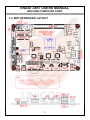
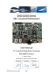
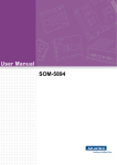
1-4. MOTHERBOARD LAYOUT.
9
ENDAT-3857 USERS MANUAL
UNICORN COMPUTER CORP.
Chapter 2. Setting up the Motherboard
2-1. Connectors / Headers and Jumpers
Connectors Overview:
Function
Connectors
Cooling Fan Connector
DC Power Supply Connector
HDD Power Connector
USB3.0 Port0 Connector
USB 2.0 Port1 Connector
USB 2.0 Port2
USB 2.0 Port3 Header
LAN 1 Port Connector
LAN 2 Port Connector
SATA Connector
DDR3L RAM Socket
CRT Output Connector
Mini DP Port Connector
24/48 bit LCD Panel Connector
PWM Backlight Control Connector
COM1 Box Header
COM2 Box Header
HD Audio Speaker Output
Half-sized Mini-PCIe Socket
Full-sized Mini-PCIe Socket
Battery Connector
PS/2 Mouse/KB Pin Header
SM BUS Pin Header
Speak Out, Line-Out Pin Header
Line-In、MIC-In Pin Header
SPDIF Pin Header
DIGITAL I/O Pin Header
FAN1
CN7
HDDPWR1
CN4
CN4
Full-sized Mini PCIe
J4 / Half-sized Mini PCIe
CN5
CN6
SATA1
DIMM1
CN10
CN8
LVDS1
CN3
CN2
CN1
CN9
MPCIE2
MPCIE1
J5
J1
SMB1
J7
J6
J8
J3
10
ENDAT-3857 USERS MANUAL
UNICORN COMPUTER CORP.
Jumpers Overview:
Function
LCD Voltage (LCD-PWR) Select
LVDS1 LCD Backlight Voltage (VBL) Select
LCD Backlight Active (BLEN) Voltage Select
Clear CMOS
COM1/2 Voltage Selector
SATA Port Pin7 Select (for +5V/GND)
USB Port3 share to Half-sized Mini PCIe slot
Header for Case Panel
HDD LED
External Speaker
Buzzer On/Off
Hardware Reset Switch
ATX Power Supply On/Off Switch
Power LED
WDT Function Enable/Disable
Connectors
JP4
JP2
JP3
JBAT1
JP5,
JP6
JUSBP1
JP1 Pin1(-)–2(+)
JP1 Pin3(-)–6(+)
JP1 Pin4–5
JP1 Pin7–8
JP1 Pin9–10
JP1 Pin11(-)–12(+)
JP1 Pin13–14
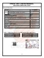
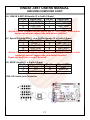
JBAT1: CMOS Data Clear & Clear ME Register (2x3 with 2.0mm)
RTCRST_N
SRTC_RST_N
Normal
2-4*
Normal
1-3*
Clear CMOS
4-6
Clear CMOS REG
3-5
11
ENDAT-3857 USERS MANUAL
UNICORN COMPUTER CORP.
J1: PS/2 Keyboard / Mouse Header (2x5 with 2.0mm)
Pin No. Signal (KB)
Pin No.
Signal (MS)
1
KB Data
2
MS Data
3
KEY
4
KEY
5
GND
6
GND
7
+5V(DC)
8
+5V(DC)
9
KB_CLK
10
MS_CLK
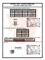
J4: USB Port3 Pin Header (1x5 with 2.54mm)
Pin No.
Function
1
USB_VCC
2
USBD3
USBD+
4
USB_GND
5
KEY
JUSBP1: USB Port3 share to Half-sized Mini PCIe slot (2x3 with 2.0mm)
J4 *
Mini PCIE slot
JUSB1
1-3,2-4
3-5,4-6
Notice: The JUSBP1 jumper setting for USB Port3 share to Half-sized mini
PCIe slot.
12
ENDAT-3857 USERS MANUAL
UNICORN COMPUTER CORP.
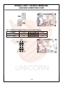
CN1(COM2),CN2(COM1): Serial port Box Headers (2x5 with 2.0mm)
Pin No.
Function
Pin No.
Function
1
DCD
6
DSR
2
RXD
7
RTS
3
TXD
8
CTS
4
DTR
9
RI
5
GND
10
N.C.
Serial Cable D-SUB Type Connector Pin Mapping
Pin No.
Function
Pin No.
Function
1
DCD
6
DSR
2
RXD
7
RTS
3
TXD
8
CTS
4
DTR
9
RI
5
GND
COM2 port (RS-485 2 Wire)
Pin No.
Function
Pin No.
1
Data –
6
2
Data +
7
3
NA
8
4
NA
9
5
NA
Function
NA
NA
NA
NA
COM2 port (RS-422 4 Wire)
Pin No.
Function
Pin No.
1
–TXD
6
2
+RXD
7
3
+TXD
8
4
–RXD
9
5
NA
Function
NA
NA
NA
NA
13
ENDAT-3857 USERS MANUAL
UNICORN COMPUTER CORP.
JP5: COM Port Voltage Selector (2x6 with 2.0mm)
Voltage
+12V(DC)
R.I. *
+5V(DC)
JP5 (COM1)
1-2
3-4
5-6
JP5 (COM2)
7-8
9-10
11-12
14
ENDAT-3857 USERS MANUAL
UNICORN COMPUTER CORP.
J6: LINE-IN & MIC-IN Header (2 x 4 with 2.0mm)
Pin No.
Signal (KB)
Pin No.
Signal (MS)
1
LINE_IN_R
2
MIC_ R
3
JACK_DETECT
4
JACK_DETECT
5
GND_AUD
6
GND_AUD
7
LINE_IN_L
8
MIC_ L
Notice: Please connect the jack detect pin to “GND_AUD” if the actual
connector cannot support the jack detect function!
J7: Speak Out(amplifier), Line-OutPin Header (2 x 4 with 2.0mm)
Pin No.
Signal (KB)
Pin No.
Signal (MS)
1
FRONT_L
2
LINE_OUT_L
3
JACK_DETECT
4
JACK_DETECT
5
GND_AUD
6
GND_AUD
7
FRONT_R
8
LINE_OUT_R
Notice: Please connect the jack detect pin to “GND_AUD” if the actual
connector cannot support the jack detect function!
Sepak out and Line out can’t be used.
J8: SPDIF Header (1 x 5 with 2.0mm)
Pin No.
Signal (KB)
1
+5V
2
N.C
3
SPDIF-OUT
Pin No.
4
5
CN9: HD Audio jack Connector
15
Signal (MS)
GND
SPDIF-IN
ENDAT-3857 USERS MANUAL
UNICORN COMPUTER CORP.
SATA Connector :
JP6: SATA Port Pin7 Select +5V/GND (1x3 with 2.0mm)
SATA Port
GND *
+5V
SATA1
1-2
2-3
16
ENDAT-3857 USERS MANUAL
UNICORN COMPUTER CORP.
LVDS1: Single/Dual Channel LVDS(18/24/36/48 bit only, 1.25mm)
MB: DF-13A-40DP-1.25V / Map: DF13-40DS-1.25C
Pin No.
1
3
5
7
9
11
13
15
17
19
21
23
25
27
29
31
33
35
37
39
Signal
VBL
GND
BLEN
LCD-PWR
GND
Odd 0+
Odd 1+
Odd 2+
Odd 3+
Odd CLK+
GND
Pin No.
2
4
6
8
10
12
14
16
18
20
22
24
26
28
30
32
34
36
38
40
Even 0+
Even 1+
Even 2+
Even 3+
Even CLK+
LCD-PWR
GND
GND
VBL
Signal
VBL
GND
GND
LCD-PWR
GND
Odd 0Odd 1Odd 2Odd 3Odd CLK GND
Even 0-.
Even 1Even 2Even 3Even CLKLCD-PWR
GND
GND
VBL
Please make sure the Pin 1 location before plug-in LCD connector.
Please leave pin 23rd ~ pin 32nd unconnected if the single channel LVDS
function is needed.
Please double check "jumper setting & LCD cable's orientation" before
power-on, any incorrect installation may caused damaged of the LCD.
17
ENDAT-3857 USERS MANUAL
UNICORN COMPUTER CORP.
JP2: LCD Voltage Select (2x3 with 2.0mm)
Voltage
+3.3V *
+5V
JP2 (LVDS1)
1-2
3-4
+12V
5-6
JP4: LCD Backlight Voltage Select (1x3 with 2.0mm)
Voltage
+5V *
+12V
JP4 (LVDS1)
1-2
2-3
JP3: LCD Backlight Control Voltage Select (1x3 with 2.0mm)
Voltage
+3.3V *
+5V
JP3 (LVDS1)
1-2
2-3
CN3: LCD Backlight Control Connector (Map: PHR-6)
Pin No.
Signal
1
GND
2
LVDS_BKLT_CTRL
3
PWRDN
4
BLUP
5
BLDN
6
GND
18
ENDAT-3857 USERS MANUAL
UNICORN COMPUTER CORP.
Notice:
PWRDN for Backlight On/Off Control:
When receiving active low pulse (0V) from this pin3 (PWRDN).
Example:
Using button switch on Pin1_GND & Pin3_ PWRDN.
LVDS_BKLT_CTRL for backlight brightness dimming:
PWM duty cycle range: from 30~100%, the output frequency from PWM Out can
be up to 400 kHz and Voltage level is +3.3V
Example:
Using button switches on “Pin6_GND & Pin4_ BLUP” and “Pin6_GND & Pin5_
BLDN”.
The Pin2_ LVDS_BKLT_CTRL connect to LCD Panel Backlight Dimming Pin
(Sample: AUO G190EG02_V1)
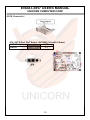
CN8: Mini DP Connector
Notice:
DP dongle converter
The ENDAT-3857 supports DP port for digital display output, please note the
dongle should connect either passive(recommend) or active type .
19
ENDAT-3857 USERS MANUAL
UNICORN COMPUTER CORP.
J3: Digital I/O Header (2x7 with 2.0mm)
Pin No.
Function
Pin No.
1
+5V
2
3
DIO-OUT0
4
5
DIO-OUT1
6
7
DIO GND
8
9
DIO-OUT2
10
11
DIO-OUT3
12
13
+3.3V
14
SMB1: SM BUS Header (1 x 5 with 2.0mm)
Pin No.
Signal (KB)
Pin No.
1
SMB_CLK
4
2
+3.3V
5
3
IR_RX
FAN1: Cooling Fan Connector
Pin No.
1
2
3
4
Function
+5V
DIO-IN0
DIO-IN1
DIO GND
DIO-IN2
DIO-IN3
+3.3V
Signal (MS)
SMB_DATA
GND
Signal
GND
+12V
Sensor Pin
PWM(Fan1 Only)
20
ENDAT-3857 USERS MANUAL
UNICORN COMPUTER CORP.
J5: Battery connector (1x2 1.25mm)
Pin No.
Signal
1
+V
2
GND
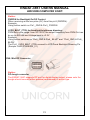
CN7: Power input 9KD-014A-L (2.5mm DC JACK)
HDDPWR1: DC Output connector (1x4 with 3.96mm)
Pin No.
Signal
1
+12V
2
GND
3
GND
4
+5V
21
ENDAT-3857 USERS MANUAL
UNICORN COMPUTER CORP.
2-2. Installing Memory
The DDR3L SO-DIMM socket of ENDAT-3857 supports up to 8GB memory. The speed of
DDR3L memory can be DDR3-1333.
2-3. Shared VGA Memory
The ENDAT-3857 built-in Intel® Atom™ SoC integrated Gen7 4EUs Gfx graphic
engine with DVMT 4.0 up system memory. The amount of video memory on motherboard
determines the number of colors and the video graphic resolution.
2-4. Watch Dog Timer
Watch dog Timer (WDT) is a special design for system monitoring to secure the
system work normally. WDT has an independent clock from the oscillator and could
set time and clear/refresh WDT counter function. When time is up, WDT will send
hardware RESET signal to reset system.
Timeout Value Range
-1 to 255
-Second or Minute
22
ENDAT-3857 USERS MANUAL
UNICORN COMPUTER CORP.
Sample code (using TurboC/C++ 3.0):
#include <stdio.h>
#include <dos.h>
#include <dir.h>
void show_ver();
void main()
{
unsigned int tt;
clrscr();
show_ver();
tt=0;
while((tt==0)||(tt>255))
{
printf("\n\nPlease key in how many seconds you want to reset system (1~255):");
scanf("%d",&tt);
}
outportb(0x2e,0x87);
//Unlock register
outportb(0x2e,0x87);
//Unlock register
outportb(0x2e,0x07);
//set Logic Device number pointer
outportb(0x2f,0x08);
//set Logic Device number
outportb(0x2e,0x30);
//set WDTO active
outportb(0x2f,0x01);
//set reg value active (bit0 =1 active,0 inactive )
outportb(0x2e,0xf2);
//set WDTO Control Mode
outportb(0x2f,0x00);
//set register value Default :00h
//bit7 Mouse interrupt reset enables watch-dog timer reload
// 0: Watchdog Timer I is not affected by mouse interrupt.
// 1: Watchdog Timer I is reset by mouse interrupt.
// bit6 Keyboard interrupt reset enables watch-dog timer reload
// 0: Watchdog Timer I is not affected by keyboard interrupt.
// 1: Watchdog Timer I is reset by keyboard interrupt.
outportb(0x2e,0xf0);
//set WDTO Control Mode
outportb(0x2f,0x00);
//set register value Default :00h
// (bit3=1: minute. =0: second)
outportb(0x2e,0xf1);
//set WDT Counter
outportb(0x2f,tt);
//set time out value of WDT
}
void show_ver()
{
unsigned char tmp0;
printf("Designed by attila of UNICORN computer corp. \n2014/10/10 release
version:1.0a\n");
printf("This program is design for test Watch Dog Timer for ENADT-3857 (NCT6106D).\n");
}
23
ENDAT-3857 USERS MANUAL
UNICORN COMPUTER CORP.
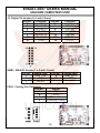
2-5. Digital I/O
Pin define:
J2: Digital I/O Header (2x7 with 2.0mm)
Pin No.
Function
Pin No.
1
+5V
2
3
DIO-OUT0
4
5
DIO-OUT1
6
7
DIO GND
8
9
DIO-OUT2
10
11
DIO-OUT3
12
13
+3.3V
14
Function
+5V
DIO-IN0
DIO-IN1
DIO GND
DIO-IN2
DIO-IN3
+3.3V
Digital I/O port address:
This function is support by onboard super I/O chip; it can be control easily by
change the register of super I/O chip via I/O port “2Eh” and “2Fh”. Please see
the sample code of below for implement. Voltage tolerance: +/- 5% with 0V to
+5V.
Sample code for input (using Turbo C/C++ 3.0):
bit No
7
6
5
4
3
2
1
0
DIO-I3
DIO-I2
DIO-I1
DIO-I0
NA
NA
NA
NA
Map
Sample code for input (using Turbo C/C++ 3.0)
#define input_port 0x2f // Digital input data port
Unsigned char read_data;
outportb(0x2e,0x87);
//Unlock register
outportb(0x2e,0x87);
//Unlock register
outportb(0x2e,0x07);
//set Logic Device number pointer
outportb(0x2f,0x07);
//set Logic Device number
outportb(0x2e,0x30);
//set Device Active
outportb(0x2f,0x04);
// set Bit 2 =GPIO2 ; 0=Inactive / 1= Active Default: FCh
outportb(0x2e,0xE8);
// set GPIO Output / Input Port
outportb(0x2f,0xF0);
// 0=Output/ 1=Input
// Bit 0~3 DIO-O0~ DIO3 / Bit4~7 DIO-I0~DIO-I3.
outportb(0x2e,0xE9);
//Read DIO-Input register.
//Bit7~Bit4 = DIO-I3~DIO-I0.(Read Only)
read_data=inportb(input_port); // Read digital input data
printf("DIO-Input=%02X\n",read_data); //Show digital input data on screen
24
ENDAT-3857 USERS MANUAL
UNICORN COMPUTER CORP.
Sample code for output (using Turbo C/C++ 3.0):
bit No
7
6
5
4
3
2
NA
NA
NA
NA
DIO-O3
DIO-O2
Map
1
0
DIO-O1
DIO-O0
Sample code for output (using Turbo C/C++ 3.0)
outportb(0x2e,0x87);
outportb(0x2e,0x87);
outportb(0x2e,0x07);
outportb(0x2f,0x07);
outportb(0x2e,0x30);
outportb(0x2f,0x04);
outportb(0x2e,0xE8);
outportb(0x2f,0xF0);
outportb(0x2e,0xE9);
outportb(0x2f,0xnm);
//Unlock register
//Unlock register
//set Logic Device number pointer
//set Logic Device number
//set Device Active
// set Bit 2 =GPIO2 ; 0=Inactive / 1= Active Default: FCh
// set GPIO Output / Input Port
// 0=Output/ 1=Input
// Bit 0~3 DIO-O0~ DIO3 / Bit4~7 DIO-I0~DIO-I3.
//Read DIO-Input register.
// n=DIO-I0~DIO-I3 / m=DIO-O0~DIO-O3.
Bit7~Bit3 = DIO-I3~DIO-I0.(Read Only)
25
ENDAT-3857 USERS MANUAL
UNICORN COMPUTER CORP.
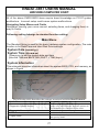
Chapter 3. Phoenix UEFI BIOS SETUP
BIOS menu screen
Setup Menu
The menu bar on top of the screen has the following main items:
> Main
For changing the basic system configuration.
> Advanced
For changing the advanced system setting.
> Super IO
For changing the system IO configuration.
> Security
For changing the security system setting.
> Boot
For changing the system boot configuration.
> Exit
For select the exit options and loading default setting.
Use the BIOS CMOS setup program to modify the system parameters to reflect the
environment installed in your system and to customize the system as desired.
Long Press the <F2> key to enter into the BIOS CMOS setup program when you
turn on the power. Settings can be accessed via arrow keys. Press <Enter> to
choose an option to configure the system properly.
In the main menu, press F10 or “SAVE & EXIT SETUP” to save your changes and
reboot the system. Choose “Exit Saving Changes” to ignore the changes and exit
the setup procedure. Pressing <ESC> at anywhere during the setup will return to
the main menu.
26
ENDAT-3857 USERS MANUAL
UNICORN COMPUTER CORP.
All of the above CMOS BIOS items require board knowledge on PC/AT system
architecture. Incorrect setup could cause system malfunctions.
Navigating Setup Menus and Fields
Navigation (moving your cursor around, selecting items, and changing them) is
easy in Setup.
Following setting belongs to standard function setting:
Main Menu
The Standard Setup is used for the basic hardware system configuration. The main
function is for Data/Time and Hard Disk Drive settings.
˙System Date (mm:dd:yy)
˙System Time (hh:mm:ss)
Allows you to set the system date and time
(Use the TAB and BACKTAB (SHIFT + TAB) keys.)
˙System Information
This submenu provides information about the system BIOS, CPU, and memory, as
shown in Figure
The following table describes the settings associated with the Boot Features.
Enables OEM Logo
Quick Boot
Diagnostic Splash Screen
Diagnostic Summary Screen
UEFI Boot
Legacy Boot
Enables graphical POST, including animation,
sound, icons, advertisements, and other multimedia
objects that may be configured by the OEM.
Enables the diagnostic summary screen.
Enables the Unified Extensible Firmware Interface.
Enable this option to bypass some drivers
and speed up POST.
27
ENDAT-3857 USERS MANUAL
UNICORN COMPUTER CORP.
Advanced Menu
The following table describes the settings associated with the CPU Configuration menu.
Intel SpeedStep Technology
C-States
Intel SpeedStep technology is Intel’s new power
saving technology. Processors can switch between
multiple frequencies and voltage points to enable
power saving. The default value is [Enabled].
Configuration options:
[Enabled] and [Disabled]. If you install Windows R
8 / 8.1 and want to enable this function, please set
this item to [Enabled]. This item will be hidden
if the current CPU does not support Intel SpeedStep
technology.
Enable CPU C States Support for power saving. It
is recommended to keep C3, C6 and C7 all enabled
for better power saving.
The following table describes the settings associated with the Graphics Configuration
menu.
IGD – Boot Type
IGD – Secondary Boot Type
LVDS Active
Panel Resolution
Integrated Graphics Device
Primary Display Selection.
Aperture Size
Spread Spectrum clock
Select the Video Device activated during POST.
This has no effect if external graphics are present.
Select the Video Device activated during UEFI
POST , MS-DOS & Linux Not Support .
En/Disable DP Port LVDS
Select LCD (DP LVDS) resolution.
800x600x18bit, 1024x768x18bit,
1024x768x24bit, 1280x768x18bit,
1280x800x18bit, 1280x960x18bit
1280x1024x48bit, 1366x768x18bit
1366x768x24bit, 1440x900x48bit,
1400x1050x48bit, 1600x900x48bit
1680x1050x48bit, 1600x1200x48bit
1920x1080x48bit, OEM Resolution.
Onboard Graphics Device En/Disable
Select the primary display port device.
Select the Onboard Graphics Device base Memory
size.
En/Disable clock chip spread spectrum feature.
28
ENDAT-3857 USERS MANUAL
UNICORN COMPUTER CORP.
The following table describes the settings associated with the South Cluster
Configuation menu.
PCI Express Configuration
Configuration PCIe Speed Type
PCIe 0 ~ 3 Speed
Control the PCI Express Root Port
PCI Express Root Port 0 , 3 , 4
USB Configuration
En/Disable Wake-up By USB Keyboard/Mouse
Wake-up By USB
USB3.0 Support.
xHCI Mode
USB OTG Support.
USB OTG Support
Control the EHCI (USB2.0 PORT) Support.
EHCI Controller
Audio Configuration
En/Disable HD Audio
Azalia Device
Storage Configuration
En/Disable SATA Port
SATA Controller
Select the SATA controllers operation mode.
SATA Mode
LAN Configuration
LAN2 Device En/Disable
LAN2 Controller
Wake On LAN Support
Wake On LAN Enable
Boot On LAN PXE ROM
PXE ROM
Others Menu
The following table describes the settings associated with the SIO Configuration.
Hardware Monitor
Setting CPU Fan
Smart Fan Feature
Super IO Configuration
Setting Serial Port 1~2
Serial Port
Select Serial 2 type: RS232, RS485, RS422.
COM2 Type
For RS485, RS422 Termination.
UART2 Termination
Setting Paraller Port
Paraller Port
Select SIO Watch Dog Timer
Watch Dog Timer Select
Select Always On/Off, Former State.
Power Failure – Power Control
Advanced Power Management
RTC Wake Up Setting.
Power On By Alarm
Security Menu
The following table describes the settings associated with the Security Configuration.
Set Supervisor Password
Set BIOS Setup Password .
Boot Menu
This submenu provides information about the Boot devices boot priority.
29
ENDAT-3857 USERS MANUAL
UNICORN COMPUTER CORP.
Chapter 4. VGA, DP Port and drivers
4-1.
Graphic controller Feature
The ENDAT-3857 integrated a high performance Intel® Atom™ SoC integrated
Gen7 4EUs Gfx engine. Support Microsoft DirectX11, OpenGL3.2, OpenCL1.1,
OpenCL2.0 on Windows, and Full HW acceleration, decode: H.264, MPEG2/4,
VC-1, WMV9. Encode: H.264, MPEG2
GPU Type: HD
Base frequency (MHz): 542
Maximum frequency (MHz): 792
The build-in Graphics Controller’s main features include:
- Hardware frame buffer compression improves UMA (Unified Memory
Architecture) memory efficiency
- VGA resolution up to 1920 x 1200
- Mini DP (DP Port B)
- LVDS (DP port C) resolution up to 1920x1080
30
ENDAT-3857 USERS MANUAL
UNICORN COMPUTER CORP.
4-2.
Driver Utility Installation Guide
1.
When finishing the installation of Microsoft Windows System, please install the relative
Intel® chipsets (INF), display and AUDIO driver manually for compliance compatibility
of hardware environment.
2.
Please contact sales department of UNICORN for Embedded OS user driver
(Linux, Windows CE and Windows Embedded). All of embedded OS driver is
not be included in any versions of driver CD-ROM from UNICORN.
Please download or check from Intel® web site: www.intel.com for more
information or last versions of driver as needs!
31
ENDAT-3857 USERS MANUAL
UNICORN COMPUTER CORP.
Appendix A: FLASH MEMORY UTILITY
Using this package to update the system BIOS from a disk file to the on board Flash memory.
Be aware any improper update of the system BIOS will cause the malfunction of the system.
Method of update BIOS:
1.
Please contact one of the Sales Representative on behalf of Unicorn to acquire
“BIOS update package”, and process following procedures for the BIOS UPDATE.
2.
Unzip “BIOS Update package” into the root bootable storage.
3.
Boot to Shell mode.
Please skip “Disk error” and press any key to restart to shell mode.
4.
Shell mode command :
a.
fs0: (switch to the root of the USB flash drive.)
b.
Type the " Update " command to start flash BIOS processes.
5.
Once the BIOS is Flash successfully, Reboot the system.
6.
Press <F2> to enter BIOS Setup, Load BIOS setup default <F9>, save BIOS
default and exit <F10>.
* Please turn off system and clear CMOS data by JBAT1.
* Please restart your system and load setup default.
.
32
ENDAT-3857 USERS MANUAL
UNICORN COMPUTER CORP.
Appendix B: LVDS PIN ASSIGNMENT
LVDS1: Single/Dual Channel LVDS(18/24/36/48 bit only, 1.25mm)
MB: DF-13A-40DP-1.25V / Map: DF13-40DS-1.25C
Pin No.
1
3
5
7
9
11
13
15
17
19
21
23
25
27
29
31
33
35
37
39
Signal
VBL
GND
BLEN
LCD-PWR
GND
Odd 0+
Odd 1+
Odd 2+
Odd 3+
Odd CLK+
GND
Pin No.
2
4
6
8
10
12
14
16
18
20
22
24
26
28
30
32
34
36
38
40
Even 0+
Even 1+
Even 2+
Even 3+
Even CLK+
LCD-PWR
GND
GND
VBL
Signal
VBL
GND
GND
LCD-PWR
GND
Odd 0Odd 1Odd 2Odd 3Odd CLK GND
Even 0-.
Even 1Even 2Even 3Even CLKLCD-PWR
GND
GND
VBL
Please make sure the Pin 1 location before plug-in LCD connector.
Please leave pin 23rd ~ pin 32nd unconnected if the single channel LVDS
function is needed.
Please double check "jumper setting & LCD cable's orientation" before
power-on, any incorrect installation may caused damaged of the LCD.
33
ENDAT-3857 USERS MANUAL
UNICORN COMPUTER CORP.
Appendix C: CH7511B Backlight Control
CN3:LCD Backlight Control Connector (Map: PHR-6)
Pin No.
Signal
1
GND
2
LVDS_BKLT_CTRL
3
PWRDN
4
BLUP
5
BLDN
6
GND
Notice:
PWRDN for Backlight On/Off Control:
When receiving active low pulse (0V) from this pin3 (PWRDN).
Example:
Using button switch on Pin1_GND & Pin3_ PWRDN.
LVDS_BKLT_CTRL for backlight brightness dimming:
PWM duty cycle range: from 30~100%, the output frequency from PWM Out can
be up to 400 kHz and Voltage level is +3.3V
Example:
Using button switches on “Pin6_GND & Pin4_ BLUP” and “Pin6_GND & Pin5_
BLDN”.
The Pin2_ LVDS_BKLT_CTRL connect to LCD Panel Backlight Dimming Pin
(Sample: AUO G190EG02_V1)
34
ENDAT-3857 USERS MANUAL
UNICORN COMPUTER CORP.
Appendix D: LIMITED WARRANTY
Standard Two years limited warranty on all our ENDAT series all-in-one
motherboards and embedded board. Products that become defective during the
warranty period shall be repaired, or subject to manufacturer’s option, replaced.
The limited warranty applies to normal proper usage of the hardware and does not
cover products that have been modified or subjected to unusual electrical or
physical stress. Unicorn Computer Corp is not liable to repair or replace defective
goods caused by improper using or use of unauthorized parts. The following
situations will be charged:
1. The products during the warranty but defective caused by improper using or
artificial external pressure and result in the components damages. According to
the damage situation, the manufacturer has the rights to decide to repair or not.
The manufacturer will charge the parts/repair cost and the returning shipping
charge.
2. The products out of warranty will charge the parts/repair cost and the returning
shipping charge as per the repair status.
3. The manufacturer has the rights to decide to repair or not based on the stock of
parts for the products which are phased out of the production.
4. Please e-mail or fax the RMA Service Request Form when have the defective
products.
35
ENDAT-3857 USERS MANUAL
UNICORN COMPUTER CORP.
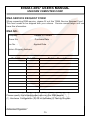
RMA SERVICE REQUEST FORM
When requesting RMA service, please fill out this “RMA Service Request Form”.
This form needs to be shipped with your returns. Service cannot begin until we
have this information.
RMA NO.:
Company:
Person to Contact:
Phone No:
Purchase Date :
Fax No. :
Applied Date :
Return Shipping Address:
Model No.
Serial No.
Problem Description
Please specify the following when returning the RMA boards:
(1) Hardware Configuration (2) OS or Software (3) Testing Program
__________________
Authorized Signature
36