1
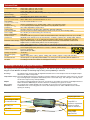
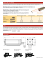
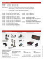
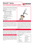
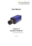
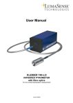
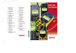
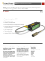
IMPAC Infrared Thermometers
IMPAC pyrometer with fiber optics for non-contact measurements of low temperatures
on metals, ceramics, graphite etc. between 100 and 750°C
IP 140-LO
● Temperature ranges from 100°C
● Short response times
● Extremely small spot sizes
● Built-in digital display with temperature indication
● Parameter adjustments via integrated
key pad or interface
● Laser targeting light
● Test current output
● Interface RS232 / RS485 switchable
The IP 140-LO is a digital, highly accurate pyrometer with fiber optics for
non-contact measurement of low
temperature on metals, ceramics,
graphite etc. from 100°C.
The instrument is equipped with a
fibre and an exchangeable optical
head. The fibre and optical head are
unaffected by electromagnetical interferences (e.g. induction).
For optimal match of the instrument
to the application 2 different optics
are available.
The pyrometer is equipped with a
built-in LC display and a small keyboard for setting of the pyrometer
parameters. Additionally it can be
connected to a PC via serial interface RS232 or RS485 (switchable).
The standard analyzing and parametrizing software InfraWin is included in scope of delivery.
The pyrometer has a laser targeting
light for exact alignment onto the
measuring object.
Typical applications:
•
•
•
•
•
•
•
•
•
•
•
metal moulds
pressing tools
bearings, bearing housings
preheating
annealing
tempering
sintering
soldering
rolling
brazing
normalizing
Technical Data
Temperature ranges:
Subrange:
Spectral range:
Signal processing:
Accuracy:
(ε = 1, t90 = 1 s, Tamb = 23°C)
Repeatability:
100 to 650°C (MB 6.5) with 1 m fibre
110 to 670°C (MB 6.7) with 2 m fibre
130 to 750°C (MB 7.5) with 5 m fibre
any range adjustable within the temperature range, minimum span 51°C
2 to 2.6 µm
alternating light signal, digitized immediately
below 400°C: 2°C
above 400°C: 0.3% of measured value in °C +1°C
0.1% of measured value in °C +1°C
(ε = 1, t90 = 1 s, Tamb = 23°C)
Resolution:
Response time t90:
Emissivity ε:
Analog output:
Test current output:
Power supply:
Power consumption:
Serial interface:
Parameters:
interface and display: 0.1°C, analog output: < 0.03 % of temperature range
1.5 ms (with dynamical adaption at low signal levels) adjustable up to 10 s
10 to 100% adjustable in steps of 0.1%
linear 0 to 20 mA or 4 to 20 mA, DC, switchable; load max. 500 Ohm
fixed 10 mA (for 0 to 20 mA analog output) or fixed 12 mA (for 4 to 20 mA analog output)
24 V AC/DC (14 to 30 V AC/DC) (AC: 48 to 62 Hz)
max. 6 VA
switchable inside the pyrometer: RS232 or RS485 addressable, half duplex; baud rate up to 115 kBd
adjustable at the instrument or via serial interface: emissivity; response time; analog output; address;
baud rate; waiting time; °C or °F; setting of the maximum value storage; temperature sub range
Maximum value storage: single or double storage; cleared by: preselected time interval or external deletion contact or via
digital interface or automatically with the next measuring object
Isolation:
power supply, digital interface, analog output are galvanically isolated against each other and housing
Protection class:
IP65 (DIN 40 050)
Sighting:
Laser targeting light (max. power level < 1 mW, λ = 655 nm, CDRH class II)
Ambient temperature:
0 to 53°C at housing,
optical head up to 200°C
Storage temperature:
-20 to 60°C
Dimensions [mm]:
see right side
Weight:
approx. 970 g (with 1 m fibre), approx. 1020 g (with 2 m fibre), approx. 1210 g (with 5 m fibre)
Mechanical tests:
vibration proof corresponding DIN EN 60068-2-6, shock proof corresponding DIN EN 60068-2-27
CE-label:
according to EU directives about electromagnetic immunity
Advantages of the Digital Signal Processing
The signal processing of series 140 pyrometers is fully digital, i.e. the detector signal are digitized immediately and digitally processed. With this technique an extremely high accuracy and repeatability is achieved.
Accuracy:
The high accuracy is achieved by the digital linearisation of the sensor output as well as the digital compensation for the ambient temperature.
Temperature range: Due to the digital technique any temperature sub range within the full temperature range can be set. The analog measuring output corresponds automatically to the selected sub range. This setting of a sub range does
not effect the high accuracy and repeatability.
Output:
The analog measuring outputs 0 to 20 mA or 4 to 20 mA are selectable as well as the serial digital interfaces
RS232 or RS485. Additionally the interface allows the controlling of the pyrometer via PC.
Bus control:
The serial interface RS485 facilitates the integration of the pyrometer into existing field bus systems.
Calibration:
A calibration of the series 140 pyrometer can be done with help of a PC and a calibration source without
opening the housing.
Converter
Targeting light button
Fiber with green mark
on instrument’s side
LC-Display for
temperature or
paramters, keyboard for
parameter settings
inside the instrument
Mounting rail
Type label
Optical head
Power supply,
analog output,
digital interface
Optics and Laser Aiming
Depending on the application the instrument will be delivered with a small or a large optical head. The selection of the optical head
depends not only on its size but also on the required spot size (size of the measuring object) and the measuring distance.
Optical head I: With the very small dimensions the optical head I is suited for use in confined spaces. The
optics is adjusted to one of the measuring distances mentioned in the table. The mentioned spot size will
be achieved in exactly this distance (other distances on request).
Optical head II: The optics II is bigger, but smaller spot sizes can be achieved. Two
designs are available, fixed adjusted or focusable:
Similar to optics I the fixed adjusted type is adjusted to one of the measuring distances
mentioned in the table (other distances on request).
The focusable type is available for 3 different distance ranges. Each measuring distance
can be adjusted within the mentioned limits to achieve the smallest spot size in the required distance.
a
M
D
Distance „a“ is specified
from the front of the lens
Measuring distance a [mm]
Spot size M90 [mm]
Aperture D [mm]
Type I
120
260
3.4
8.5
7
7
Type II
(fixed adjusted)
87
200
1.1
2.5
17
15
88 to 110
95 to 129
105 to 161
1.1 to 1.6
1.3 to 2.1
1.6 to 2.8
17.5 to 15.5
16.5 to 14.5
15 to 13.5
Optical head
Type II
(focusable)
Fiber
The transmission between optical head and converter is done via 0.6 mm mono fibre with a stainless steel protection hose. The optical head contains only the lens, the sensor and the electronics are located in the converter. Fiber and optical head can be used in ambient temperatures up to 200°C without additional cooling (fibre at converter side max. 125°C). The temperature of fibre and optical
head must be at least 30°C lower than the measuring temperature. The length of the fiber depends on the temperture ranges (see
technical data)
Minimum bending radius: For short time: 150 mm
Permanent:
500 mm
Dimensions
Pyrometer housing:
Optical head type I:
Optical head type II:
(fixed adjusted)
Optical head type II:
(focusable)
All dimensions in mm
Reference Numbers
Pyrometers:
3 875 910
3 875 930
3 875 920
100 to 650°C (MB 6.5) with 1 m fibre
110 to 670°C (MB 6.7) with 2 m fibre
130 to 750°C (MB 7.5) with 5 m fibre
Scope of delivery:
Converter, fiber, one selectable optical head, works certificate, InfraWin operating and
analizing software, user manual. A connection cable is not included in scope of delivery.
Ordering example:
Pyrometer with reference number, optical head (I or II) with measuring distance
(e.g. optical head I, a = 120 mm), connection cable (e.g.3 820 330)
Accessories:
3 820 340
connection cable, length 5 m, 90° connector
3 820 530
connection cable, length 10 m, 90° connector
3 820 540
connection cable, length 15 m, 90° connector
3 820 830
connection cable, length 20 m, 90° connector
3 820 840
connection cable, length 25 m, 90° connector
3 820 550
connection cable, length 30 m, 90° connector
3 820 330
connection cable, length 5 m, straight connector
3 820 500
connection cable, length 10 m, straight connector
3 820 510
connection cable, length 15 m, straight connector
3 820 810
connection cable, length 20 m, straight connector
3 820 820
connection cable, length 25 m, straight connector
3 820 520
connection cable, length 30 m, straight connector
3 834 280
mounting angle for converter
3 834 370
mounting angle for optical head I (fixed)
3 834 380
mounting angle for optical head I (adjustable)
3 834 390
ball and socket mounting for optical head I or II
3 834 230
adjustable mounting support for optical head II
3 835 170
3 835 180
3 835 240
3 852 290
3 890 640
3 890 650
3 890 560
3 890 520
3 826 500
air purge for optical head I
air purge for optical head II
90° mirror for optical head II
Power supply NG DC; 100 - 240 VAC
⇒ 24 V DC, 1 A
LED digital display DA 4000-N
LED digital display DA 4000: with 2 limit switches
LED digital display DA 6000-N: with possibility for
pyrometer parameter settings for digital
IMPAC pyrometers; RS232 interface
LED digital display DA 6000; DA 6000-N additional
with 2 limit switches and analog input and output
HT 6000, portable battery driven indicator and
instrument for pyrometer parameter setting
Overview Accessories
Air purge units:
Mounting
angle for
optical head I
Adjustable
mounting support
for optical head II
Mounting angle
for converter
Electrical accessories:
Air
purge unit
for optical head II
LEDlarge display
Air
purge unit
for optical head I
Ball and socket
mounting for optical
head I or II
90°mirror
LED digital display
DA 6000-N
Power supply
NG DC
LumaSense Technologies
Americas and Australia
Sales & Service
3301 Leonard Court
Santa Clara, CA 95054
Europe, Middle East, Africa
Sales & Service
D-60326 Frankfurt, Germany
Kleyerstr. 90
India
Sales & Support Center
Mumbai, India
China
Sales & Support Center
Shanghai, China
Tel.: +1 408 727-1600
Fax: +1 408 727-1677
Tel.: +49 69 97373-0
Fax: +49 69 97373-167
Tel.: +91 22 67419203
Fax: +91 22 67419201
Tel.: +86 21 5882 2277
Fax: +86 21 5887 0077
[email protected]
© 2010 LumaSense Technologies, Rev. 12/2010. All rights reserved.
Visit lumasenseinc.com for local sales representation
Specifications are subject to change without notice
Mounting: