1
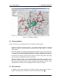
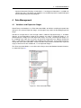
DIG
SILENT
PowerFactory
I N T E G R AT E D P O W E R S Y S T E M A N A LY S I S S O F T W A R E
DIgSILENT
PowerFactory 15
What´s New
Version 15.0
DIgSILENT GmbH
Heinrich-Hertz-Straße 9
72810 Gomaringen / Germany
Tel.: +49 (0) 7072-9168-0
Fax: +49 (0) 7072-9168-88
[email protected]
Please visit our homepage at:
http://www.digsilent.de
Copyright ©2012 DIgSILENT GmbH
All rights reserved. No part of this
publication may be reproduced or
distributed in any form without permission
of DIgSILENT GmbH.
November 2012
r474
1
CONTENTS
CONTENTS
Contents
1
Introduction . . . . . . . . . . . . . . . . . . . . . . . . . . . . . . . . . . . . . . .
5
2
Graphical User Interface . . . . . . . . . . . . . . . . . . . . . . . . . . . . . . .
5
2.1
Project Overview Window . . . . . . . . . . . . . . . . . . . . . . . . . .
5
2.2
Redesign of Main Menu . . . . . . . . . . . . . . . . . . . . . . . . . . .
6
2.3
Redesign of Dialogue Tabs . . . . . . . . . . . . . . . . . . . . . . . . .
6
2.4
User Profiles: Customizable Toolbars, Menus and Dialogue Boxes . . .
6
2.5
Standard and Base Package User Profiles . . . . . . . . . . . . . . . . .
7
Network Graphics . . . . . . . . . . . . . . . . . . . . . . . . . . . . . . . . . . .
8
3.1
Geographic Diagrams . . . . . . . . . . . . . . . . . . . . . . . . . . . .
8
3.2
Colouring Modes . . . . . . . . . . . . . . . . . . . . . . . . . . . . . . .
9
3.3
Miscellaneous . . . . . . . . . . . . . . . . . . . . . . . . . . . . . . . . .
9
Data Management . . . . . . . . . . . . . . . . . . . . . . . . . . . . . . . . . . .
10
4.1
Variations and Expansion Stages . . . . . . . . . . . . . . . . . . . . . .
10
4.2
External References . . . . . . . . . . . . . . . . . . . . . . . . . . . . .
11
Database and License Server . . . . . . . . . . . . . . . . . . . . . . . . . . . .
11
5.1
Offline Mode . . . . . . . . . . . . . . . . . . . . . . . . . . . . . . . . .
11
5.2
Housekeeping . . . . . . . . . . . . . . . . . . . . . . . . . . . . . . . . .
11
5.3
Selective DB Migration . . . . . . . . . . . . . . . . . . . . . . . . . . . .
12
5.4
User Authentication on License Server . . . . . . . . . . . . . . . . . . .
12
General . . . . . . . . . . . . . . . . . . . . . . . . . . . . . . . . . . . . . . . . .
12
6.1
Calculation Modes . . . . . . . . . . . . . . . . . . . . . . . . . . . . . .
12
6.2
Invalidation of Calculation Results . . . . . . . . . . . . . . . . . . . . . .
12
6.3
Flexible Data Page . . . . . . . . . . . . . . . . . . . . . . . . . . . . . .
12
6.4
Variable Selection
. . . . . . . . . . . . . . . . . . . . . . . . . . . . . .
12
6.5
Hot Keys . . . . . . . . . . . . . . . . . . . . . . . . . . . . . . . . . . . .
13
Reliability Analysis Functions . . . . . . . . . . . . . . . . . . . . . . . . . . . . .
13
7.1
Reliability Assessment . . . . . . . . . . . . . . . . . . . . . . . . . . . .
13
7.1.1
Optimal Power Restoration . . . . . . . . . . . . . . . . . . . .
14
7.1.2
Unbalanced Calculations . . . . . . . . . . . . . . . . . . . . .
14
3
4
5
6
7
2
CONTENTS
7.2
CONTENTS
7.1.3
Feeder Constraints . . . . . . . . . . . . . . . . . . . . . . . .
14
7.1.4
Reliability Indices . . . . . . . . . . . . . . . . . . . . . . . . .
14
7.1.5
Load Distribution States . . . . . . . . . . . . . . . . . . . . . .
14
7.1.6
Tariffs . . . . . . . . . . . . . . . . . . . . . . . . . . . . . . . .
15
. . . . . . . . . . . . . . . . . . . . . . . . .
15
Distribution Network Tools . . . . . . . . . . . . . . . . . . . . . . . . . . . . . .
15
8.1
Tie Open Point Optimization . . . . . . . . . . . . . . . . . . . . . . . . .
15
8.2
Voltage Profile Optimization . . . . . . . . . . . . . . . . . . . . . . . . .
16
8.3
Backbone Calculation . . . . . . . . . . . . . . . . . . . . . . . . . . . .
17
8.4
Optimal Remote Control Switch (RCS) Placement . . . . . . . . . . . .
17
Cable Sizing . . . . . . . . . . . . . . . . . . . . . . . . . . . . . . . . . . . . . .
17
9.1
Cable Reinforcement . . . . . . . . . . . . . . . . . . . . . . . . . . . . .
17
9.2
Automatic Cable Sizing . . . . . . . . . . . . . . . . . . . . . . . . . . . .
17
10
Techno-Economical Calculation . . . . . . . . . . . . . . . . . . . . . . . . . . .
18
11
Protection . . . . . . . . . . . . . . . . . . . . . . . . . . . . . . . . . . . . . . .
19
11.1
Tabular Relay Settings Reports . . . . . . . . . . . . . . . . . . . . . . .
19
11.2
Relay Settings Input . . . . . . . . . . . . . . . . . . . . . . . . . . . . .
19
11.3
Short Circuit Trace . . . . . . . . . . . . . . . . . . . . . . . . . . . . . .
19
12
Arc-Flash Hazard Analysis . . . . . . . . . . . . . . . . . . . . . . . . . . . . . .
19
13
Motor Starting . . . . . . . . . . . . . . . . . . . . . . . . . . . . . . . . . . . . .
20
14
Simulation Scan . . . . . . . . . . . . . . . . . . . . . . . . . . . . . . . . . . . .
20
15
Models . . . . . . . . . . . . . . . . . . . . . . . . . . . . . . . . . . . . . . . . .
21
15.1
Secondary Substation . . . . . . . . . . . . . . . . . . . . . . . . . . . .
21
15.2
MV Load Model . . . . . . . . . . . . . . . . . . . . . . . . . . . . . . . .
21
15.3
Voltage Transformer Model Enhancements . . . . . . . . . . . . . . . . .
22
15.4
Static Generator Model Enhancements . . . . . . . . . . . . . . . . . . .
23
15.5
PLL Model Enhancements . . . . . . . . . . . . . . . . . . . . . . . . . .
23
15.6
Asynchronous Motor Model Enhancements . . . . . . . . . . . . . . . .
23
15.7
Series Capacitor Model Enhancements . . . . . . . . . . . . . . . . . .
23
15.8
Cable Parameter Calculation Enhancements . . . . . . . . . . . . . . .
23
15.9
2- and 3-Winding Transformer Model Improvements . . . . . . . . . . .
24
8
9
Optimal Power Restoration
3
CONTENTS
16
CONTENTS
15.10
Station Controller Model Enhancements . . . . . . . . . . . . . . . . . .
24
15.11
External Grid Model Enhancements . . . . . . . . . . . . . . . . . . . .
25
15.12
AC-Voltage Source Enhancements . . . . . . . . . . . . . . . . . . . . .
25
Documentation . . . . . . . . . . . . . . . . . . . . . . . . . . . . . . . . . . . . .
25
4
2
1
GRAPHICAL USER INTERFACE
Introduction
This document highlights some of the new key features and enhancements available in PowerFactory 15.0. Specific details of all enhancements, including examples, and associated Technical References are available in the PowerFactory 15 manual.
2
2.1
Graphical User Interface
Project Overview Window
A new Project Overview Window will appear in the main application window which displays an
overview of the project allowing the user to assess the state of the project at a glance while also
facilitating easy interaction with the key project objects. It gives an overview of study cases,
operational scenarios, variations, grids, and triggers.
This improves the fact that in previous versions of PowerFactory it was often necessary to interrogate the data manager to ascertain and influence the state of these key project objects. For
large projects in particular, this could be a little unwieldy and so the Project Overview Window
has been introduced to overcome these difficulties.
Figure 2.1, shows an example of the Project Overview Window.
Figure 2.1: Project Overview Window
5
2.2
Redesign of Main Menu
2.2
2
GRAPHICAL USER INTERFACE
Redesign of Main Menu
The Main Menu structure has been re-engineered and consolidated to facilitate the use of PowerFactory . The new structure of the main menu is in close accordance with the toolbars. Additional main menu entries have been made available, which were previously only accessible
via toolbar icons. Most notably, the new Main Menu item View collects functions of the Graphic
Board. Also note that several functions moved from the File menu to the new Insert menu.
2.3
Redesign of Dialogue Tabs
PowerFactory 15.0 introduces a completely new look and feel of the dialogue tabs.
Figure 2.2 represents the changes between PowerFactory 15.0 and the previous version. The
original tabs are now presented as a menu, and the original second page is now presented as
a tab.
Figure 2.2: Redesign of Dialogue Tabs
2.4
User Profiles: Customizable Toolbars, Menus and Dialogue Boxes
PowerFactory 15.0 includes new functionality to customize the graphical user interface (GUI),
including the ability to:
• Fully configure Main Toolbar, Graphic Board Toolbar and Drawing Toolbar. This includes
definition of custom DPL Commands and Templates with user-defined icons.
• Customize the element dialogue pages that are displayed.
• Customize element dialogue parameters. Parameters can be Hidden (not shown) or Disabled (shown but not edited).
• Customize Main Menu and context-sensitive menu commands.
Customization is done with user Profiles.
Profiles are created in the Configuration → Profiles folder by selecting the New Object icon
and then Others → Settings→ Profile. An Administrator can create and customize profiles, and
control User/User Group selection of profiles from the Profile tab of each user group.
6
2.5
Standard and Base Package User Profiles
2
GRAPHICAL USER INTERFACE
Profiles can be used to configure toolbars, menus, dialogue pages, and dialogue parameters.
Figure 2.3 illustrates aspects of the GUI that may be customized using Profiles.
Figure 2.3: Toolbars and Dialogue Boxes Customization
2.5
Standard and Base Package User Profiles
PowerFactory 15.0 already comes with two pre-defined profiles: “Base Package” and “Standard”, these are selectable from the main menu under Tools → Profiles (See Figure 2.4).
Figure 2.4: User Profiles
Selecting the “Base Package” profile limits Main Menu entries and icons shown on the Main
Toolbar to those that are used with the Base Package of the software. The “Standard” profile
includes the full graphical user interface for all available PowerFactory functions. Figures 2.5a
7
3
NETWORK GRAPHICS
and 2.5b show the main Toolbar for the Base Package and the Standard profile, respectively.
(a) Base Package Profile
(b) Standard Profile
Figure 2.5: Standard and Base Package User Profiles
3
3.1
Network Graphics
Geographic Diagrams
PowerFactory 15.0 comes with a new Geographic Diagram concept. A Geographic Diagram
can be generated with a 1-click action via Main Menu Insert → Geographic Diagram, once GPS
coordinates of the network components are available (see Description tab of Branches/Lines
and Substations/Terminals).
Geographic Diagrams support background maps of various common projection types. The
graphical symbol, e.g. the circle’s displayed size of a substation, is independent of the zoom
level — an elegant approach to ensure that graphics are easy to view as the user zooms in and
out of the diagram. Besides, it can be adjusted from which scale level texts and result boxes
become visible.
For better identification of load/generation clusters, new special layers ”Load/Generation Distribution” have been introduced that graphically represent the magnitude of network load and
generation with circles of proportional sizes.
An example of a Geographic Diagram is shown in Figure 8.1.
8
3.2
Colouring Modes
3
NETWORK GRAPHICS
Figure 3.1: Geographic Diagram
3.2
Colouring Modes
Several new features are included for Single Line Diagram colouring modes:
• Support of Continuous Colouring modes. This colouring option interpolates displayed
colours on Single Line Diagram between predefined discrete colour tables, e.g. for Voltages/Loading.
• New colouring modes, including modes for Primary Equipment such as Year of Construction, Cross Section, Forced Outage Rate/Duration, as well as topology information such
as colourings according to Supplying Substation or Supplying Transformer are available.
• Extension of the Voltages/Loading colouring mode to visualize Voltage Drop and Voltage
Rise in feeders of a distribution network are provided.
• New alarm colouring modes, such as Feeder Radiality Check : When a Feeder has been
defined as Feeder is supposed to be operated radially, an alarm colouring mode is available to indicate whether or not the feeder is actually operated radially. If not, the Feeder
(including the non-radial path) will be highlighted on the single line diagram.
3.3
Miscellaneous
• In addition to the known Rectangular Selection of network elements in the single line
graphic, PowerFactory 15.0 introduces a new Free-Form Selection tool.
9
4
DATA MANAGEMENT
• Improved Automatic Drawing of Substations: If no diagram information is available for
equipment inside a substation, new algorithms are available to provide an optimized layout
for an automatically generated diagram.
4
4.1
Data Management
Variations and Expansion Stages
PowerFactory 15.0 introduces an ”Error Correction Mode” to facilitate recording of network data
changes in the relevant Expansion Stage, even though it may not be the Recording Expansion
Stage.
Consider an example where a line of length 10 km is added in ”Expansion Stage 1”, and other
changes, to an independent section of the network, are made in ”Expansion Stage 2”. As
determined by the Study Time, both Expansion Stages are active, and ”Expansion Stage 2” is
the recording stage. Now, the user wishes to correct the length of the line added in ”Expansion
Stage 1” from 10 km to 12 km. Rather than modifying the Study Time, it is possible to make the
change with ”Error Correction Mode” enabled, and the change will be recorded to the expansion
stage, in which the line was introduced, i.e. to ”Expansion Stage 1”.
The ”Error Correction Mode” is accessible via the Project Overview Window, Network Variations,
as showed in Figure 4.1
Figure 4.1: Error Correction Mode
10
4.2
4.2
External References
5
DATABASE AND LICENSE SERVER
External References
PowerFactory 15.0 include a new option to Pack External References of a project. Using this
function, all external references of a project are resolved by copying the reference objects to a
local folder called ”External”. In addition, the user may define locations which shall be omitted
in checking for external references.
This new function helps avoiding problems when sharing projects with third party users that
may/should not have access to, e.g., certain libraries.
5
5.1
Database and License Server
Offline Mode
PowerFactory 15.0 provides the ability to work in Offline Mode when a network connection to the
multi-user database server and license server is unavailable. An illustration of the architecture
for the Offline Mode is depicted in Fig. 7.1.
The required project data is cached to the user’s local machine, which can then later be synchronized to the server database. Offline Mode functionality includes the ability to lock and
unlock projects, edit projects, and limit the database size on the computer(s) working in offline
mode.
Figure 5.1: Architecture for Offline Mode
5.2
Housekeeping
PowerFactory 15.0, for multi-user databases, offers the ability to execute some project administration via a scheduled overnight housekeeping task. In this way project purging, emptying
of user recycle bins and deletion of old projects can be automatized. This can let users activate projects more quickly and also speed up quitting PowerFactory . Moreover, housekeeping
moves heavy data processing to off-peak periods, offering better performance for normal daytime users.
11
5.3
5.3
Selective DB Migration
6
GENERAL
Selective DB Migration
When upgrading to PowerFactory 15.0, it is necessary to migrate the PowerFactory database
to the new version. For very large databases this can take significant processing time. If the
database contains many projects that are no longer needed, PowerFactory 15.0 offers means to
shorten the migration time by migrating just the projects that the user wants to keep, according
to selection criteria. Selective Migration is only available for multi-user databases (e.g. Oracle,
SQL Server).
5.4
User Authentication on License Server
The license server can now be configured to grant licenses only to a list of named PowerFactory
users.
6
6.1
General
Calculation Modes
In PowerFactory 15.0 distinct calculation modes are better supported. In particular, PowerFactory distinguishes any Load Flow based calculation method (such as Contingency Analysis,
Sensitivity Analysis, Optimal Power Flow, etc.) which allows for improved predefined results in
single line diagrams and flexible data pages, as well as better adaption of colouring modes.
6.2
Invalidation of Calculation Results
Under User Settings, there is a new option for Invalidation of Calculation Results. The user can
optionally select to Show last results. When selected, modifications to network data or switch
status etc. will not invalidate the calculation results. The results will instead be shown on the
single line diagram and on flexible data pages in grey until the user invalidates the results (e.g.
by selecting Reset Calculation, or conducting a new calculation).
6.3
Flexible Data Page
In PowerFactory 15.0, the user may customize the number format per column in the Flexible
Data Page. Also, the names of the headers for the individual columns are user-definable (refer
to Chapter ”Data Manager” in the User’s Manual for more information about how to customize
the Flexible Data page).
6.4
Variable Selection
PowerFactory 15.0 introduces a completely new look and feel of Variable Set dialogue. An
example of the variable set object is shown in Figure 6.1. Here the variable set for a load (red
circle) is shown. PowerFactory 15.0 distinguishes more function types for better grouping of the
calculation quantities (see also Section 6.1). In this case an RMS simulation (green circle) is
to be performed and the total active and the reactive power flowing to the load are going to be
12
6.5
Hot Keys
7
RELIABILITY ANALYSIS FUNCTIONS
monitored (blue circle). Moreover, selection now can be made by ticking the boxes next to the
variables, thus, the variable description texts remain visible.
Figure 6.1: Variable Selection
More information about the Variable Selection could be found in the User’s Manual, Chapters
”Study Cases” and ”Reporting and Visualizing Results”.
6.5
Hot Keys
PowerFactory 15.0 includes new Hot Keys for Load Flow and Short-Circuit calculation, as well
as for reset calculation.
• Load Flow: Press F10 for a Load Flow calculation, and Crtl+F10 to edit the Load Flow
options.
• Short-Circuit: Press F11 for a Short-Circuit calculation, and Crtl+F11 to edit the ShortCircuit options.
• Reset Calculation: Press F12.
7
7.1
Reliability Analysis Functions
Reliability Assessment
The Reliability Assessment function has been largely improved in PowerFactory 15.0.
13
7.1
7.1.1
Reliability Assessment
7
RELIABILITY ANALYSIS FUNCTIONS
Optimal Power Restoration
The algorithms for Power Restoration in distribution networks have been further improved.
Power Restoration is now incorporating Tie Open Point Optimization methods to achieve an
utmost level of resupply. I.e., PowerFactory is automatically evaluating — as part of the Power
Restoration strategy — the benefits of any move of tie open points in any neighboring feeder.
Figure 7.1: Example for Optimal Power Restoration strategy incorporating a reconfiguration of
Tie Open Points: The two pictures show the initial situation and the restored case, respectively,
for a fault occuring at the marked location in the green feeder.
7.1.2
Unbalanced Calculations
Reliability calculations now supports both, balanced and unbalanced network representations.
7.1.3
Feeder Constraints
In addition to Thermal Constraints and Voltage Constraints, the Reliability Assessment calculation provides an option to consider feeder Voltage Drop/Rise Constraints. This is particularly
important in distribution networks with high portions of generation, where bidiretional power
flows may occur.
7.1.4
Reliability Indices
Reliability Indices can be calculated based on subscribed power.
7.1.5
Load Distribution States
In PowerFactory 15.0, a new Distribution Curve object has been introduce. Such an object may
be used to define the Load Distribution (for a year) measured at a given substation. Reliability Assessment will automatically calculate its indices based on this distribution. This largely
improves the accuracy of the results compared to a worst-case scenario consideration.
14
7.2
Optimal Power Restoration
8
DISTRIBUTION NETWORK TOOLS
Figure 7.2: Example of a discretized load distribution curve
7.1.6
Tariffs
The addition of Time Tariffs and Energy Tariffs provide enhanced flexibility to define load interruption costs for Reliability Assessment.
7.2
Optimal Power Restoration
In PowerFactory 15.0, a new module Optimal Power Restoration is available. The corresponding
toolbar is depicted in Fig. 9.1.
Optimal Power Restoration studies can be conducted for single case to obtain a ”Recovery
Scheme Report” — even in the case where no failure data is available for the network components. This function includes the feature to trace the stages of the restoration and view the
impacts of the restoration on the single line graphic. An optimal power restoration strategy can
be quickly performed for a single case by right-clicking a single element and selecting Calculate→Optimal Power Restoration.
Figure 7.3: Optimal Power Restoration toolbar with options for tracing and reporting.
8
Distribution Network Tools
8.1
Tie Open Point Optimization
In PowerFactory 15.0, further improvements are provided for the Tie Open Point Optimization.
• Tie Open Point Optimization now supports both balanced and unbalanced network representations.
15
8.2
Voltage Profile Optimization
8
DISTRIBUTION NETWORK TOOLS
• New objective functions have been made available. Besides the classical ”Minimization of
Losses”, the user may now also chose to optimize the tie open points for a best-fit with
regards to ”Minimization of (certain) Reliability Indices”, such as SAIFI or ENS. Combined
cost curves for costs of losses and the costs of reliability impacts are also available.
• The user may select the switch types (circuit-breaker, disconnector, switch disconnector,
load-break-switch) and control types (remote controlled, indicator of of short circuit, manual) to be considered by the Tie Open Point Optimization command.
8.2
Voltage Profile Optimization
PowerFactory 15.0 introduces a new Voltage Profile Optimization for Distritbution networks with
potential bidirectional power flow due to embedded generation conditions.
The new Voltage Profile Optimization command calculates an optimization of distribution transformer tap change positions with consideration to the range of expected load and generation
conditions. Expected voltage drop and voltage rise conditions in the LV grids are taken into
account, allowing for a combined study of MV and LV voltage profiles.
An improved voltage profile plot facilitates the visualization of results.
Figure 8.1: Example of a Voltage Profile Optimization for bidirectional power flows: The voltage
profile plots simultaneously show load (blue curve) and generation (green curve) case studies
including worst-case voltage drops and rises at LV feeder ends.
16
8.3
Backbone Calculation
8.3
9
CABLE SIZING
Backbone Calculation
The new Backbone Calculation command facilitates the determination (and visualization) of
the main connections between meshed feeders. Various methods are available to determine
backbones, ranging from purely topological criteria, and cross-section analysis, to more sophisticated methods that score quality of power restoration.
Besides, new backbone objects have been introduced with calculation quantities that give valuable insight into the structure and potential power restoration of a distribution grid.
8.4
Optimal Remote Control Switch (RCS) Placement
A new Optimal RCS Placement function is introduced which optimizes the RCS locations within
feeders to minimize Energy Not Served (ENS), balance ENS, or minimize Expected Interruption
Costs (EIC).
The command allows to produce the results in a new variation for easy comparison of beforeand-after optimization results.
Remote controlled switches can nicely be visualized in the single line diagram with the aid of a
corresponding newly introduced graphic layer.
9
Cable Sizing
9.1
Cable Reinforcement
The Cable Reinforcement analysis has been further improved:
• The analysis can be performed on a network model without any cable types previously
defined. PowerFactory will assign types from the selected library, with consideration to the
specified loading and voltage drop constraints.
• The Cable Reinforcement method includes a function to report on the short-circuit loading
of lines and cables.
• A Cable Reinforcement analysis can be performed on unbalanced networks.
9.2
Automatic Cable Sizing
PowerFactory 15.0 provides a new functionality to perform Cable Sizing optimization in accordance with various international standards.
The Cable Sizing command can be executed on a network model, balanced or unbalanced,
with or without any cable types previously defined. PowerFactory will assign types and calculate
cable ratings according to the selected international standard, such as
• IEC 60364-5-52
• BS 7671
17
10
TECHNO-ECONOMICAL CALCULATION
• NF C15-100
• NF C13-200
Figure 9.1: Cable Sizing input dialogue of a cable
10
Techno-Economical Calculation
PowerFactory 15.0 introduces a new techno-economical calculation to perform an economic
assessment of network expansions through an analysis of:
• The cost of electrical losses.
• The economic impact of failure rates (reliability).
• Investment costs (including initial costs, initial value, scrap value, and expected life span).
• Project timing.
The output of the Techno-Economical Calculation is the Net Present Value (NPV) of the project
over the selected period. The command can optionally reconfigure the network at each step of
the calculation to minimize losses (using the Tie Open Point Optimization command).
18
12
11
11.1
ARC-FLASH HAZARD ANALYSIS
Protection
Tabular Relay Settings Reports
PowerFactory 15.0 introduces a completely new tabular reporting format which vastly improves
the protective device setting reporting capability of the software. With the previous approach
ASCII reports for protection settings were generated in the output window which were not able
to deal with the structure of complex relay models. Furthermore the settings could not easily be
exported to other software environments like Microsoft Word or Excel. The new tabular report
command (ComTablereport) overcomes these problems by generating pre-configured tabular
outputs customized to the protective device class.
11.2
Relay Settings Input
It is now possible to enter reach settings for distance relay zones in terms of Primary Amperes
or Secondary Amperes. This functionality gives the user flexibility to configure distance relay
models as required by their particular application or according to the restrictions of the relay
model.
11.3
Short Circuit Trace
The Short Circuit Trace is a tool based on the complete short circuit calculation method that
allows the user to examine the performance of a protection scheme in response to a fault or
combination of faults; where the response is examined in time steps and where at each time
step, the switching outcomes of the previous time step and the subsequent effect on the flow of
fault current, is taken into consideration.
12
Arc-Flash Hazard Analysis
PowerFactory 15.0 introduces new tools to conduct Arc-Flash hazard assessments:
• Arc-Flash calculations can be conducted in accordance with IEEE-1584 2002 and NFPA
70E 2008 standards.
• Arc-Flash calculations can be performed using globally or individually specified circuitbreaker tripping times, or protection clearing times based on actual protection settings.
The calculation takes into account the arc resistance when determining protection clearing
times.
• Incident Energy and PPE requirements can be displayed on the Single Line Graphic.
• PowerFactory automates the preparation of Arc-Flash labels based on the calculation results. An example label produced using the default template is shown in Figure 8.1.
19
14
SIMULATION SCAN
Figure 12.1: Example Arc-Flash Label
13
Motor Starting
In addition to dynamic motor starting simulations, PowerFactory 15.0 introduces the ability to
perform static motor starting simulations to assess motor voltages before, during, and after
starting, and to assess whether starting is successful.
14
Simulation Scan
PowerFactory 15.0 comes with new Simulation Scan modules to monitor network results and
parameters during time-domain simulations. Multiple modules, monitoring the same or different
quantities, can be defined for a given simulation. If a defined limit is exceeded, an action to
display an output message or a “Stop Simulation” event can be triggered (likewise a trip generator in the case of the loss of synchronism scan module). Limits that can be monitored are as
follows:
• Frequency maximum and minimum limits.
• Synchronous machine loss of synchronism.
• User-selected parameter maximum and minimum limits.
• Voltage maximum limit and maximum voltage violation time, and minimum limit and minimum voltage violation time.
• Voltage recovery and voltage recovery time.
Fig. 14.1 illustrates the smooth integration of the Simulation Scan functionality into the existing
simulation module.
20
15
MODELS
Figure 14.1: Simulation Scan objects monitoring simulation results with various trigger conditions.
15
15.1
Models
Secondary Substation
PowerFactory 15.0 includes a new Secondary Substation object. The application provides templates ( ) with a broad variety of predefined secondary substation configurations.
15.2
MV Load Model
PowerFactory 15.0 includes a new MV Load model, representing a distribution transformer together with a reduced load/generation model.
21
15.3
Voltage Transformer Model Enhancements
Figure 15.1: MV Load Model
15.3
Voltage Transformer Model Enhancements
In PowerFactory 15.0 the following new models are supported:
• Detailed VT Model:
Figure 15.2: Detailed VT Model
• Detailed CVT Model (Capacitive Voltage Transformer):
Figure 15.3: Detailed CVT Model
22
15
MODELS
15.4
15.4
Static Generator Model Enhancements
15
MODELS
Static Generator Model Enhancements
The following enhancements are available in PowerFactory 15.0:
• New Single Phase and Single Phase-Neutral Model
• The 3-phase model can now be used as a Reference Machine (Slack) in load flow calculation
• Frequency-Dependence of r2, x2 and r0, x0 for harmonic calculation
15.5
PLL Model Enhancements
• New Single Phase and Single Phase-Neutral Model
• Support of blocking in under-voltage condition
15.6
Asynchronous Motor Model Enhancements
For Motor Starting the following enhancements are supported:
• Starting ”Reactor”
• Starting ”Auto Transformer”
• Support of ”speed” or ”time” trigger in Motor Starting methods
15.7
Series Capacitor Model Enhancements
For Spark Gap Model a built-in tripping unit is now supported including the following tripping
criteria:
• Trip according to current or voltage
• For Metal Oxide Varistor: Trip according to current or MOV Energy/MOV Power
15.8
Cable Parameter Calculation Enhancements
• Cable definition can now be selected as type in the line
• Improvements for cross-bonded cables
• Improvements for reduction of insulation layers
• Coordinates of circuits in pipe are represented in polar coordinates (see Fig. 15.4)
• Material selection in accordance with IEC60287 (see Fig. 15.5)
• Support of segmental conductors
23
15.9
2- and 3-Winding Transformer Model Improvements
15
• Frequency characteristic for the definition of the AC resistance of the conductor
Figure 15.4: Polar Coordinates
Figure 15.5: Material Selection
15.9
2- and 3-Winding Transformer Model Improvements
• Transformer measurement tables now include zero-sequence impedance data
• Additional input option ”Reactance and Resistance in p.u.” for transformer types
15.10
Station Controller Model Enhancements
PowerFactory 15.0 supports various additional control methods:
24
MODELS
15.11
External Grid Model Enhancements
16
DOCUMENTATION
• Support of cosphi(P )-Characteristic
• Support of Q(V )-Characteristic
• Reactive Power Distribution according to Voltage Setpoint Adaption
• Now also supporting PWM Converters
15.11
External Grid Model Enhancements
For Harmonic Analysis the following model extensions are available:
• Support of SkV , psikV input parameter
• Support of Harmonic Voltage Table
• Support of IEC6100 Background Harmonics
• Frequency dependence for R1,L1,R0,L0,R2,L2
15.12
AC-Voltage Source Enhancements
For Harmonic Analysis, Background Harmonics are supported according to IEC6100.
16
Documentation
The vastly revised User Manual is now presented in PDF format, which makes it easier to
navigate and to find specific topics in the document.
25
DIgSILENT GmbH
Company Profile
sequences, provides quick access to relay
manuals, interfaces with manufacturer
specific relay settings and integrates with
PowerFactory software, allowing for powerful
and easy-to-use settings co-ordination studies.
DIgSILENT GmbH is a consulting and software
company providing engineering services in
the field of electrical power systems for
transmission, distribution, generation and
industrial plants.
DIgSILENT GmbH was founded in 1985 and
is a fully independent, privately owned
company located in Gomaringen/Tübingen,
Germany. DIgSILENT continued expansion
by establishing offices in Australia, South
Africa, Italy, Chile, Spain and France. Thereby,
facilitating improved service following the
world-wide increase in usage of its software
products and services. DIgSILENT has
established a strong partner network in
many countries such as Mexico, Malaysia,
UK, Switzerland, Colombia, Brazil, Peru,
China and India. DIgSILENT services and
software installations have been conducted
in more than 110 countries.
DIgSILENT PowerFactory
DIgSILENT develops the leading integrated
power system analysis software PowerFactory,
which covers the full range of functionality
from standard features to highly sophisticated
and advanced applications including wind
power, distributed generation, real-time
simulation and performance monitoring for
system testing and supervision. For wind
power applications, Power Factory has
become the power industry’s de-facto standard
tool, due to PowerFactory models and
algorithms providing unrivalled accuracy and
performance.
DIgSILENT StationWare is a reliable central
protection settings database and management
system, based on latest .NET technology.
StationWare stores and records all settings
in a central database, allows modelling of
relevant workflow
PowerFactory Monitor is a flexible performance
recording and monitoring system that copes
easily and efficiently with the special requirements for system test implementation, system
performance supervision and the determination
and supervision of connection characteristics.
Numerous Monitoring Systems installed at
various grid locations can be integrated to a
Wide-Area-Measurement-System (WAMS).
PowerFactory Monitor fully integrates with
the PowerFactory software.
DIgSILENT Consulting
DIgSILENT GmbH is staffed with experts of
various disciplines relevant for performing
consulting services, research activities, user
training, educational programs and software
developments. Highly specialised expertise
is available in many fields of electrical engineering applicable to liberalised power markets and to the latest developments in power
generation technologies such as wind power
and distributed generation. DIgSILENT has
provided expert consulting services to several
prominent wind-grid integration studies.
DIG
SILENT
P o w e r Fa c t o r y
DIgSILENT GmbH
72810 Gomaringen
T +49 7072 9168-0
[email protected]
Heinrich-Hertz-Straße 9
Germany
F +49 7072 9168-88
www.digsilent.de