1
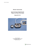
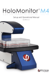
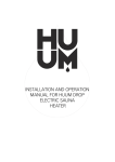
User Manual H201-NIKON-TI-S-ER November 2014 H201-NIKON-TI-S-ER Compatible with the following XY stages Nikon: Ti-S-E and Ti-S-ER H201-T-UNIT-BL Page 1 Compatible with the following Okolab Controllers www.oko-lab.com H201-NIKON-TI-S-ER User Manual November 2014 Index 1. Components and dimensions................................................................................................... 3 2. Sample Holders ................................................................................................................... 3 2.1 Available Sample Holders....................................................................................................... 3 3. Available Lids ..................................................................................................................... 4 3.1 Sliding lid .......................................................................................................................... 5 3.2 Koehler Lid ........................................................................................................................ 6 3.3 Injection Lid ...................................................................................................................... 6 3.4 Laser Interlock Lid ............................................................................................................... 7 4. Insertion of the Sample Feedback Temperature Sensor .................................................................. 8 5. Insertion of Sample Holder into Chamber ................................................................................... 8 6. Working with 35 or 60 mm Petri Dish – Spacing Rings and Magnetic Locks ........................................... 9 7. Working with 1x3’’ and 1x2’’ chamber slides - magnetic locks ........................................................11 8. Working with MW Plates - Magnetic locks and Chamber riser ..........................................................12 9. Connection of the Gas Supply ................................................................................................13 10. Working with Perfusion ........................................................................................................13 11. Connection of the Chamber with adapter ..................................................................................13 Page 2 12. Connection of the Chamber with XY stage .................................................................................15 www.oko-lab.com User Manual H201-NIKON-TI-S-ER November 2014 1. Components and dimensions H201-NIKON-TI-S-ER includes the following components: Chamber main body. It connects to the adapter with screws. Sliding glass lid for easy pipetting. Chamber riser. It is a removable frame increasing the height of the chamber from 24 to 30 mm, often required when using multi-well (MW) plates. Adapter. It connects to the Nikon XY Stage TI-S-ER with screws. Sliding Lid Distance between focal plane and upper side of the glass lid with the chamber riser Chamber Riser Distance between focal plane and upper side of the glass lid without the chamber riser Sample Holder-Order Separately Chamber Base Chamber top view Adapter Figure 1. H201-NIKON-TI-S-ER - Components and Dimensions. 2. Sample Holders 2.1 Available Sample Holders The following sample holders are available. NOTE: Please contact [email protected] if you cannot find the sample holder you are looking for. We are constantly #1 35mm Petri-dish 1xGS-M #1 1x3in. chamber slide 1xLABTEK-M #1 Lab-Tek 1in.x2in. chambered cover glass 1xLABTEK-II-M #1 Lab-Tek II 1in.x2in. chambered cover glass 1x60-M #1 60mm Petri-dish 1xT25-M #1 Nunc and Greiner T25 flask 2x35-M #2 35mm Petri-dish 2xGS-M #2 1x3in. chamber slides 2xLABTEK-M #2 Lab-Tek 1in.x2in. chambered cover glass 2xLABTEK-II-M #2 Lab-Tek II 1in.x2in. chambered cover glass www.oko-lab.com Page 1x35-M 3 adding new inserts to the list. User Manual H201-NIKON-TI-S-ER November 2014 2x60-M #2 60mm Petri-dish 4x35-M #4 35mm Petri-dish GS35-M #1 1x3in. chamber slide and #2 35mm Petri-dish LABTEK-35-M #1 Lab-Tek 1in.x2in. chambered cover glass and #2 35mm Petri- LABTEK-II-35-M #1 dishLab-Tek II 1in.x2in. chambered cover glass and #2 35mm Petri#1 dishLab-Tek 1in.x2in. chambered cover glass and #1 60mm Petri- LABTEK-60-M LABTEK-II-60-M GS60-M #1 dishLab-Tek II 1in.x2in. chambered cover glass and #1 60mm Petri#1 1x3in. chamber slide and #1 60mm Petri-dish dish 6035-M #1 60mm Petri-dish and #1 35mm Petri-dish W-LOCK-22.5 Magnetic lock to hold the standard MW plates in the chamber MW-LOCK-16.5 Magnetic lock to hold the low-profile MW plates in the chamber GS35-M For #1 1”x3”chamber slide and #2 35mm petri dishes 1x35-M For #1 35 mm petri dish LABTEK-35-M For #1 Lab-Tek 1”x2” Chambered cover glass and #2 35mm petri dishes 4x35-M For #4 35 mm petri dishes 6035-M For #2 35 mm petri dishes and #1 60mm petri dish LABTEK-60-M For #1 Lab-Tek 1”x2” Chambered cover glass and #1 60mm petri dish 2x60-M For #2 60 mm petri dishes GS60-M For #1 60mm petri dish and #1 1”x3”chamber slide 1xGS-M For #1 1”x3” chamber slide 1xLABTEK-M For #1 Lab-Tek 1”x2” Chambered cover glass 1x60-M For #1 60 mm petri dish LABTEK-60-M For #1 Lab-Tek 1”x2”chambered cover glass and #1 60mm petri dish 2xGS-M For #2 1”x3” chamber slides 1xGS-2xLABTEK-M For #1 1”x3”chamber slide and #2 Lab-Tek 1”x2” chambered cover glass 2xLABTEK-M For #2 Lab-Tek 1”x2”chambered cover glass LABTEK-II-35-M 2xLABTEK-II-M For #1 Lab-Tek II For #2 Lab-Tek 1”x2”chambered cover glass 1”x2”chambered cover glass and #2 35mm petri dishes 1xLABTEK-M For #1 Lab-Tek 1”x2”chambered cover glass Figure 2.Available sample holders. 3. Available Lids The following glass Lids are available for H201-NIKON-TI-S-ER: H201-SLIDING-LID: For easy sample loading and pipetting – Included in code H201-NIKON-TI-S-ER. H201-KOEHLER-LID*: Reduces chamber height to 21 mm and allows imaging under Koehler illumination. H201-INJECTION-LID*: Glass lid with two small openings (sealed with flexible plastic) allowing injection or permanent access to the sample. Compatible only with sample holder 1x35. H201-LASER-INTERLOCK-LID*: Glass lid with safety switch. Connects to laser controller and automatically turns laser off when lid is lifted. Compatible only with sample holder 1x35. Page 4 * OPTIONAL – not included with H201-NIKON-TI-S-ER www.oko-lab.com User Manual H201-NIKON-TI-S-ER November 2014 3.1 Sliding lid The Sliding Lid is a glass lid allowing for easy sample loading and pipetting. The Sliding Lid is screwed onto the chamber. Figure 3 shows chamber dimensions with the Sliding Lid (with and without chamber riser). Figure 4 illustrates how to remove Sliding Lid, when a different Lid is necessary. NOTE: Sliding Lid MUST BE REMOVED when using any other Lid. The Sliding Lid is fixed onto the chamber with 4 screws. Screws location is indicated by letter A in Figure 4 (image 2 and 3). Keep Sliding Lid fully closed to access screws labeled A in image 2. Open Sliding Lid to access screws labeled A in image 3. Sliding Lid Distance between focal plane and upper side of the glass lid with the chamber riser Distance between focal plane and upper side of the glass lid without the chamber riser Chamber top view Figure 3. H201-NIKON-TI-S-ER (Sliding Lid comes as standard) Screws M2x4 Sliding Lid A A 1 2 3 Page 5 Figure 4. Assembly of the sliding lid www.oko-lab.com User Manual H201-NIKON-TI-S-ER November 2014 3.2 Koehler Lid The Koehler Lid is a glass lid reducing the chamber’s height to 21 mm and allowing imaging under Koehler illumination. The Koehler Lid is placed onto the chamber (NO SCREWS or TOOLS are necessary). Figure 5 shows chamber dimensions with Koehler lid (with and without chamber riser). H201-KOHLER LID Distance between focal plane and upper side of the glass lid with the chamber riser Distance between focal plane and upper side of the glass lid without the chamber riser Chamber top view Figure 5.H201-NIKON-TI-S-ER + H201-KOEHLER-LID 3.3 Injection Lid The Injection Lid is a glass lid with two small openings sealed with flexible plastic allowing injection or permanent access to the sample. NOTE: Compatible with sample holder 1x35 ONLY. The Injection Lid is placed onto the chamber (NO SCREWS or TOOLS are necessary). Page 6 Figure 6 shows chamber dimensions with the Injection Lid (with and without chamber riser). www.oko-lab.com User Manual H201-NIKON-TI-S-ER November 2014 H201-INJECTION LID Distance between focal plane and upper side of the glass lid with the chamber riser Distance between focal plane and upper side of the glass lid without the chamber riser Chamber top view Figure 6. H201-NIKON-TI-S-ER + H201-INJECTION-LID 3.4 Laser Interlock Lid The Laser Interlock Lid is a glass lid with a safety switch connecting to the laser controller. It automatically turns the laser off when the lid is lifted. NOTE: Compatible with sample holder 1x35 ONLY. The Laser Interlock Lid is placed onto the chamber (NO SCREWS or TOOLS are necessary). Figure 7 shows chamber dimensions with the Laser Interlock Lid (with and without chamber riser). H201-LASER-INTERLOCK LID Distance between focal plane and upper side of the glass lid with the chamber riser Distance between focal plane and upper side of the glass lid without the chamber riser www.oko-lab.com Page Figure 7. H201-NIKON-TI-S-ER + H201-LASER-INTERLOCK-LID 7 Chamber top view User Manual H201-NIKON-TI-S-ER November 2014 4. Insertion of the Sample Feedback Temperature Sensor Insert the Sample Feedback Temperature Sensor through the dedicated opening located in the H201-NIKON-TI-S-ER (see Figure 8, Front and 3D views). Temperature Sensor dedicated opening Temperature Sensor dedicated opening 1.Frontal view 2.3D view Figure 8. Insertion of the temperature sensor inside the chamber. 5. Insertion of Sample Holder into Chamber Sample holders fit into the chamber base and are held in place by magnets embedded within both chamber and holder. To introduce a sample holder with the proper orientation, match the red dot on the holder to the one on the chamber base, as illustrated in Figure 9. Insert the adapter by superimposing the red points Page 8 Figure 9. Introduction of the Specimen Holder inside the Chamber Base. www.oko-lab.com User Manual H201-NIKON-TI-S-ER November 2014 6. Working with 35 or 60 mm Petri Dish – Spacing Rings and Magnetic Locks Magnetic locks prevent movement of 35 and 60 mm dishes inside the sample holder. Figure 10 illustrates the available magnetic locks for 35 and 60 mm dishes. Threaded magnetic posts allow adjusting holder’s height. Magnetic Locks for 35 and 60 mm petri dishes. Included in the corresponding sample holder Figure 10.Magnetic locks for 35 and 60 mm dish NOTE: Magnetic locks are included with sample holder. Spacing rings accounting for variability in dish diameter from one manufacturer to another are also included. Figure 11 shows how to position the ring. Ring selection guide diagrams: rings for 35 and 60 mm dish -Figure 12 and Figure 13, respectively. 1 2 3 Figure 11. 1) Insertion of the ring, 2) insertion of the 35 mm dish, 3) insertion of the magnetic lock. Page 9 NOTE: Spacing rings are included with sample holder. www.oko-lab.com User Manual H201-NIKON-TI-S-ER November 2014 BD Falcon-35x10 Willco-35x10 Grainer-Petri35x10 Ibidi μ-Dish 35 mm-low Corning-35x10 mm MatTek-P35G-X14-X Figure 12. Ring selection scheme for 35 mm dish. Ibidi μ-Dish 50 mm-low MatTek-P50G-X30-X BD Falcon-60x10 Grainer - Petri 60x15 Corning-60x15 mm Page Figure 13. Ring selection scheme for 60 mm dish. 10 Willco 60x15 www.oko-lab.com User Manual H201-NIKON-TI-S-ER November 2014 7. Working with 1x3’’ and 1x2’’ chamber slides - magnetic locks Magnetic locks prevent movement of 1’’x 3’’ and 1’’x 2’’ chamber slides inside of the sample holder. NOTE: Magnetic locks are included with sample holder. 1 2 Figure 14. Magnetic lock for 1'' x 3'' chamber slide. 3 1 2 Page 11 Figure 15. Magnetic lock for 1'' x 2'' chamber slide. To lock the slide, push simultaneously the buttons indicated with (3). www.oko-lab.com User Manual H201-NIKON-TI-S-ER November 2014 8. Working with MW Plates - Magnetic locks and Chamber riser Magnetic locks hold MW plates in place into sample holder illustrated in Figure 16 NOTE: Magnetic locks must be ordered separately (NOT INCLUDED). Product codes: MW-LOCK 22.5 and MW-LOCK 16.5. 2 Magnetic lock 1 MW-22.5-LOCK. To be ordered separately. Typically used for 6, 12, 24, 48 MW MW-16.5-LOCK. To be ordered separately. Typically used for 96 MW Figure 16. Magnetic locks for MW plates. To be ordered separately. Chamber Riser increases chamber’s height and is REQUIRED with 6, 12, 24, 48 MW plates, regardless of the Lid employed. Figure 17 shows how to install and fasten the chamber riser in place. Screws location is indicated by letter A. A Chamber Riser Chamber Base Figure 17. Riser Assembly. www.oko-lab.com Page 12 A User Manual H201-NIKON-TI-S-ER November 2014 9. Connection of the Gas Supply A single silicon tubing carries output gas from the Okolab Gas Controller to the H201-NIKON-TI-S-ER. Silicon tubing connects to a gas input - brass opening - located on a corner of the H201-NOKON-TI-S-ER. See Figure 18. Connect by gently pushing silicon tubing onto brass opening. Gas Input Figure 18. Connection with gas supply. 10. Working with Perfusion The Chamber Riser included with H201-NIKON-TI-S-ER features 12 perfusion holes for the insertion of perfusion tubing up to 2.5 mm in outer diameter. Small screws plug the perfusion holes when not in use. (Grub screws M3x6). Remove small screws as needed before introducing perfusion tubing. Figure 19 shows location of perfusion holes. Perfusion dedicated opening 1.Frontal view 2.3D view Figure 19. Perfusion 11. Connection of the Chamber with adapter Follow the steps shown in the images of Figure 20 and listed below in order to correctly install the chamber onto XY Follow the arrows shown in Figure 20 Images 1 and 2 for placing the captive screws in the proper housings 2. Place the chamber on the adapter as shown in Figure 20 Image 3 3. Use a 1.5mm metric Allen Wrench to tighten two of the four captive screws in place (A in Image 4) while keeping the sliding lid closed. (See Figure 20 Image 4) www.oko-lab.com Page 1. 13 stage: User Manual H201-NIKON-TI-S-ER November 2014 4. Tighten the remaining two captive screws (A in Image 5) while keeping the sliding lid open. 5. Image 6 of Figure 20 shows the chamber fixed on the adapter Captive Screw 1 2 3 4 A A 6 5 Page 14 Figure 20. How to assemble the chamber to the adapter. www.oko-lab.com User Manual H201-NIKON-TI-S-ER November 2014 12. Connection of the Chamber with XY stage Once you have assembled the chamber with adapter you can place it on the XY stage, following the steps shown in Figure 21. 1. Place the adapter on the stage (See Figure 21 Image 1). 2. Use the Grub screws to align correctly the adapter on the stage. Grub screws housings are indicated with letter A in Image 2 of Figure 21. 3. Follow the arrows shown in Image 3 of Figure 21 for placing flat socket head cap screws; use the provided Allen wrench for tightening the flat socket head cap screws and fastening the adapter on the stage. Screws housings are indicated with letter B in Image 4 of Figure 21. Screw M3x3 A A 1 2 Screw M4x6 B B 4 3 Page 15 Figure 21. How to fix the H201-NIKON-TI-S-ER to the XY stage. www.oko-lab.com