1
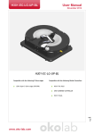
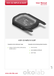
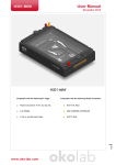
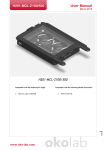
User Manual H301-UP November 2014 H301-UP Compatible with the following XY stages XY stage model and serial number must be H301-T-BL-PLUS UNO-COMBINED-CONTROLLER H401-T-DUAL Page 1 specified in purchase order. Compatible with the following Okolab Controllers www.oko-lab.com H301-UP User Manual November 2014 Index 1. Components and dimensions................................................................................................... 3 2. Sample Holders ................................................................................................................... 4 2.1 Available Sample Holders....................................................................................................... 4 Insertion of the Sample Feedback Temperature Sensor .................................................................. 5 4. Insertion of Sample Holder into Chamber ................................................................................... 5 5. Magnetic Locks ................................................................................................................... 6 6. Working with 1x3’’ and 1x2’’ chamber slides - magnetic locks ......................................................... 9 7. Connection of the Gas Supply ................................................................................................10 8. Working with Perfusion ........................................................................................................10 9. Connection of the Chamber with stage .....................................................................................11 Page 2 3. www.oko-lab.com User Manual H301-UP November 2014 1. Components and dimensions H301-UP includes the following components: Chamber base with embedded temperature sensor Chamber body, it owns 12 holes for the insertion of perfusion tubing up to 2.0 mm Objective adapter, the dimension and type of objective in use must be specified in the purchase order. Holder, the type of stage on which the chamber will fit must be specified in the purchase order. Heated Lid, it features a hinge system allowing to open and close the Lid surrounding the objective. Total chamber weight, 170g. Objective adapter Lid Side View Chamber Body Sample Holder-Order Separately Chamber base Chamber top view Holder Page 3 Figure 1. H301 UP Components and Dimensions. www.oko-lab.com User Manual H301-UP November 2014 2. Sample Holders 2.1 Available Sample Holders The following sample holders are available. NOTE: Please contact [email protected] if you cannot find the sample holder you are looking for. We are constantly adding new inserts to the list. UP-1x35-M #1 35mm Petri-dish UP-14xGS-M #1 1x3in. chamber slide UP-1xLABTEK-M #1 Lab-Tek 1in.x2in. chambered cover glass UP-1xLABTEK-II-M #1 Lab-Tek II 1in.x2in. chambered cover glass UP-1x60-M #1 60mm Petri-dish UP-1x35-M For #1 35mm Petri-dish holder UP-1xGS-M For #1 1”x3” chamber slide holders UP-1x60-M For #1 60mm Petri-dish holder UP-1xLABTEK-M For #1 1”x2” Labtek chambered cover glass holder UP-1xLABTEK-II-M For #1 1”x3”chamber slide and #2 35mm petri dishes Page 4 Figure 2.Available sample holders. www.oko-lab.com User Manual H301-UP November 2014 3. Insertion of the Sample Feedback Temperature Sensor Insert the Sample Feedback Temperature Sensor through the dedicated opening located in the H301-UP main body (see Figure 3, Frontal and 3D views). Temperature Sensor dedicated opening Temperature Sensor dedicated opening 1.Frontal view 2.3D view Figure 3. Insertion of the temperature sensor inside the chamber. 4. Insertion of Sample Holder into Chamber Sample holders fit into the chamber base and are held in place by magnets embedded within both on the chamber and on the holder. To introduce a sample holder with the proper orientation, match the red dot on the holder to the one on the chamber base, as illustrated in Figure 4. Insert the adapter by superimposing the red points Figure 4. Introduction of the Specimen Holder inside the Chamber Base. Open the lock spring, as shown in Figure 5 Image 2 2. Open the chamber lid as shown in Figure 5 Image 3 www.oko-lab.com Page 1. 5 If you want to change the sample holder follow the steps shown in the images of Figure 5 and listed below: User Manual H301-UP November 2014 3. Remove the chamber lid by lifting it from the workspace, as shown in Figure 5 Image 4 4. Remove the chamber by lifting it from workspace, as shown in Figure 5 Images 5 and 6 5. Lift and replace the sample holder, as shown in Figure 5 Image 8 2 1 Lock Spring Open Lock Spring Closed 4 3 6 5 7 8 Magnetic locks prevent movement of 35 and 60 mm dishes inside the sample holder. www.oko-lab.com Page 5. Magnetic Locks 6 Figure 5. Introduction of the Specimen Holder inside the Chamber Base. User Manual H301-UP November 2014 Figure 6 illustrates the available magnetic locks for 35 and 60 mm dishes. Threaded magnetic posts allow adjusting holder’s height. Magnetic Locks for 35 and 60 mm petri dishes. Included in the corresponding sample holder Figure 6.Magnetic locks for 35 and 60 mm dish NOTE: Magnetic locks are included with sample holder. Spacing rings with variable diameter are also included in according to the needs of the user. Figure 7 shows how to position the ring inside the sample holder. Ring selection guide diagrams: rings for 35 and 60 mm dishes -Figure 8 and Figure 9, respectively. 1 2 3 Figure 7. 1) Insertion of the ring, 2) insertion of the 35 mm dish, 3) insertion of the magnetic lock. Page 7 NOTE: Spacing rings are included with sample holder. www.oko-lab.com User Manual H301-UP November 2014 BD Falcon-35x10 Willco-35x10 Grainer-Petri35x10 Ibidi μ-Dish35mm-low Corning-35x10mm MatTek-P35G-X-14-X Figure 8. Ring selection scheme for 35 mm dish. Ibidi μ-dish 50mm-low MatTek-P50G-X-30-X BD Falcon 60x15 Grainer - Petri 60x15 Corning-60x15mm Willco60x15 Page 8 Figure 9. Ring selection scheme for 60 mm dish. www.oko-lab.com User Manual H301-UP November 2014 6. Working with 1x3’’ and 1x2’’ chamber slides - magnetic locks Magnetic locks prevent movement of 1’’x 3’’ and 1’’x 2’’ chamber slides inside of the sample holder. NOTE: Magnetic locks are included with sample holder. 1 2 Figure 10. Magnetic lock for 1'' x 3'' chamber slide. 1 3 2 Page 9 Figure 11. Magnetic lock for 1'' x 2'' chamber slide. To lock the slide, push simultaneously the buttons indicated with (3). www.oko-lab.com User Manual H301-UP November 2014 7. Connection of the Gas Supply A single silicon tubing carries output gas from the Okolab Gas Controller to the H301-UP. Silicon tubing connects to a gas input - brass opening - located on a corner of the H301-UP. See Figure 12. Connect by gently pushing silicon tubing onto brass opening. Gas Input Figure 12.Connection with gas supply. 8. Working with Perfusion The H301-UP features 12 perfusion holes on the sides for the insertion of perfusion tubing up to 2.0 mm in outer diameter. Small screws plug the perfusion holes when not in use. (Grub screws M3x6). Remove small screws as necessary before introducing perfusion tubing. Figure 13 shows the location of perfusion holes. Perfusion dedicated opening 2.3D view 1.Frontal view Page 10 Figure 13. Perfusion www.oko-lab.com User Manual H301-UP November 2014 9. Connection of the Chamber with stage H301-UP fits on the stage. To fix the chamber on the stage, follow the steps shown in Figure 14 1. Place the holder on the stage and fix it by the four pan head screws M2.5x6. The place of the pan screws is indicated by letter A.(See Figure 14 Image 1). 2. Place the chamber on the stage and fix it by the four pan head screws M2x4. The place pan screw is indicated by letter B.(See Figure 14 Image 2). 1 2 Screw M2x4 Screw M2.5x6 B A A B Page 11 Figure 14. How to fix the H301-UP on the stage www.oko-lab.com