1
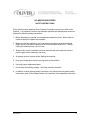
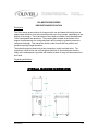
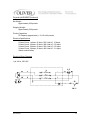
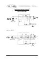
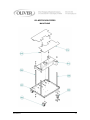
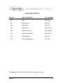
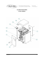
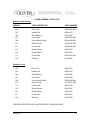
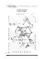
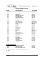
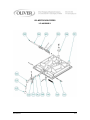
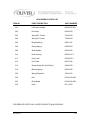
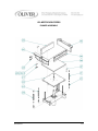
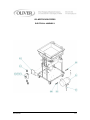
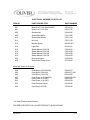
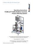
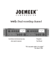
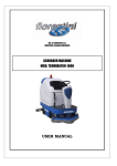
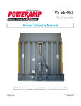
Grand Rapids, Michigan, U.S.A. 49504-5298
USER’S OPERATING AND INSTRUCTION MANUAL
MODEL 619-MDP
DOUGH PRESS
0619S20000-CV3
619-MDP DOUGH PRESS
INDEX
Section Description
Document No.
Page No.
SAFETY INSTRUCTIONS -------------------------------------- 0619S20141 --------------------------- 1-1
DESCRIPTION/SPECIFICATIONS --------------------------- 0619S20130---------------------------- 2-1
Description -------------------------------------------------------------------------------------------------- 2-1
Physical Specifications----------------------------------------------------------------------------------- 2-1
Electrical Specifications---------------------------------------------------------------------------------- 2-2
Electrical Wiring Diagrams ----------------------------------------------------------------------------- 2-1
OPERATING INSTRUCTIONS -------------------------------- 0619S20131 --------------------------- 3-1
Before You Start ------------------------------------------------------------------------------------------- 3-1
Basic Operation -------------------------------------------------------------------------------------------- 3-1
MAINTENANCE --------------------------------------------------- 0619S20132 --------------------------- 4-1
Cleaning ---------------------------------------------------------------------------------------------------- 4-1
Lubrication ------------------------------------------------------------------------------------------------- 4-1
Hydraulic Oil Specification ----------------------------------------------------------------------------- 4-1
Hydraulic Filter Replacement -------------------------------------------------------------------------- 4-1
Removing the Lid ---------------------------------------------------------------------------------------- 4-2
Replacing the Locking Hook or Cam ---------------------------------------------------------------- 4-2
Replacing a Pressing Plate ---------------------------------------------------------------------------- 4-3
Removing the Backing Plate --------------------------------------------------------------------------- 4-3
Replacing the Hydraulic Cylinder --------------------------------------------------------------------- 4-3
Removing the Motor -------------------------------------------------------------------------------------- 4-4
Changing the Pump or Coupling ---------------------------------------------------------------------- 4-4
Replacing the Control Valve ---------------------------------------------------------------------------- 4-5
TROUBLESHOOTING ------------------------------------------- 0619S20133 --------------------------- 5-1
The Ram up Light Does Not Come On -------------------------------------------------------------- 5-1
The Motor Hums but Will Not Start ------------------------------------------------------------------- 5-1
The Motor Runs but Stalls at Either End of the Cylinder’s Travel ---------------------------- 5-1
The Motor Runs Slowly but Stalls Easily before Completion of its Stroke ----------------- 5-1
The Motor Has Stalled and Can Not be Restarted ----------------------------------------------- 5-2
The Overload Relay Continually Trips --------------------------------------------------------------- 5-2
The Dough Press is Not Pressing Properly -------------------------------------------------------- 5-2
RECOMMENDED SPARE PARTS -------------------------- 0619S20134 --------------------------- 6-1
REPLACEMENT PARTS SECTION
MAIN FRAME ASSEMBLY ------------------------------------ 0619S20135 --------------------------- 7-1
Drawing ------------------------------------------------------------------------------------------------- 7-1
Parts List ----------------------------------------------------------------------------------------------- 7-2
Continued
0619S20129
0-1
INDEX (Continued)
REPLACEMENT PARTS SECTION (Continued)
Section Description
Document No.
Page No.
COVER ASSEMBLY --------------------------------------------- 0619S20136 --------------------------- 8-1
Drawing ------------------------------------------------------------------------------------------------ 8-1
Parts List ----------------------------------------------------------------------------------------------- 8-2
HYDRAULIC ASSEMBLY -------------------------------------- 0619S20137 --------------------------- 9-1
Drawing ------------------------------------------------------------------------------------------------ 9-1
Parts List ----------------------------------------------------------------------------------------------- 9-2
LID ASSEMBLY -------------------------------------------------- 0619S20138 -------------------------- 10-1
Drawing ----------------------------------------------------------------------------------------------- 10-1
Parts List ---------------------------------------------------------------------------------------------- 10-2
PUSHER ASSEMBLY ------------------------------------------ 0619S20139-------------------------- 11-1
Drawing ----------------------------------------------------------------------------------------------- 11-1
Parts List ---------------------------------------------------------------------------------------------- 11-2
ELECTRICAL ASSEMBLY ------------------------------------ 0619S20140 -------------------------- 12-1
Drawing ----------------------------------------------------------------------------------------------- 12-1
Parts List ---------------------------------------------------------------------------------------------- 12-2
WARRANTY ------------------------------------------------------- GEN 040225
WARRANTY PROCEDURE------------------------------------ GEN 040226
RETURNED PARTS POLICY --------------------------------- GEN 040227
0619S20129
0-2
619-MDP DOUGH PRESS
SAFETY INSTRUCTIONS
Every effort has been made by Oliver Products Company to provide you with a safe
machine. It is essential, however, that machine operators and maintenance personnel
observe the following safety precautions.
1. Before attempting to operate your dough press read this manual. Never allow an
untrained person to operate this machine.
2. Make sure that the machine is only connected to a properly grounded electrical
supply source of sufficient capacity for the load the divider will put on it. Always
unplug the machine when it is not in use.
3. Always make sure the machine has been disconnected and locked-out from the
power supply before cleaning or servicing.
4. All guards must be in place before starting the machine.
5. Keep your hands away from the moving parts of the machine.
6. Use only proper replacement parts.
7. Do not wear loose fitting clothing. Shirt tails should be tucked in.
8. In addition to these general safety instructions, also follow the more specific safety
instructions given for the different areas of the machine in the operating instructions.
0619S20141
1-1
THIS PAGE WAS INTENTIONALLY
LEFT BLANK.
GEN020319
619-MDP DOUGH PRESS
DESCRIPTION/SPECIFICATION
Description
The Oliver dough press consists of a hopper which can be loaded with dough from an
approximate minimum of ten and one half pounds up to forty pounds, (depending on the
density of the dough). The lid and sides of the hopper are made of hard anodized and
Teflon impregnated cast aluminum. The pressing plate located at the bottom of the
hopper is manufactured of a food grade plastic and is raised by hydraulic pressure to
compress the dough. This makes the machine ideal for puff and fine pastries and
products requiring dough lamination.
The hydraulic pump is powered by a two horsepower, totally enclosed motor. The
system has a built-in four and one half gallon hydraulic oil tank making the machine
totally self-contained and is provided with casters to allow for easy movement about the
work area.
Physical specifications
OVERALL MACHINE DIMENSIONS
0619S20130
2-1
Physical specifications (continued)
Net Weight:
Approximately 455 pounds.
Shipping Weight:
Approximately 500 pounds.
Product Capacities:
Fill Capacity (approximate) = 10-1/2 to 40 pounds
Electrical Specifications
2 Horse Power, 1 phase, 60 hertz, 230 Volts AC, 10 Amps.
2 Horse Power, 3 phase, 60 hertz, 208 Volts AC, 6.5 Amps.
2 Horse Power, 3 phase, 60 hertz, 230 Volts AC, 6.2 Amps.
2 Horse Power, 3 phase, 60 hertz, 460 Volts AC, 3.1 Amps.
Others consult factory
Electrical Wiring Diagrams
1 ph, 60 hz, 230 VAC
0619S20130
2-2
Electrical Wiring Diagrams (Continued)
3 ph, 60 hz, 208/230 VAC
3 ph, 60 hz, 460 VAC
0619S20130
2-3
619-MDP DOUGH PRESS
OPERATING INSTRUCTIONS
Before You Start
CAUTION
THE DOUGH PRESS SHOULD ONLY BE PLUGGED INTO AN OUTLET
WITH THE SAME VOLTAGE AS STATED ON THE NAMEPLATE
Before starting a new dough press with THREE PHASE electrical power for the first time
you should check to see if the motor is running in the correct direction. Remove the front
cover by removing the four thumbscrews which secure it; you will also have to remove
the handle from the directional control lever before removing the front cover. Once the
cover has been removed you should be able to see the fan end of the motor on your
dough press, this fan MUST rotate in a clockwise direction.
CAUTION
EXTENDED RUNNING OF A DOUGH PRESS WITH THE MOTOR
ROTATING IN THE INCORRECT DIRECTION WILL SEVERELY
DAMAGE THE HYDRAULIC PUMP OF YOUR MACHINE.
If the motor is rotating in the incorrect direction turn the machine off, disconnect it from
the power supply and have a qualified electrician reverse two of the three power wires in
the plug at the end of the power cord. DO NOT move the ground, (green), wire.
WARNING
ALWAYS HAVE ELECTRICAL WORK DONE BY QUALIFIED
ELECTRICIANS ONLY.
Recheck the dough press making sure that it is now running in the correct direction,
(clockwise looking at the fan end of the motor). Each time the machine is moved to a
different power supply or has electrical work done which could alter the motor rotation,
the motor must be rechecked for proper rotation.
Basic Operation
•
Make sure the floor of the hopper has been lowered before attempting to open the lid
of the divider.
•
Open the lid and load the dough into the hopper. Spread the dough over the floor of
the hopper making it approximately the same height, this is done to eliminate large
air pockets.
0619S20131
3-1
Basic Operation (Continued)
•
Close the lid and turn the handle in a clockwise direction making sure it is secure.
•
With the machine running grasp the control valve handle and lift it to start the floor of
the hopper up. Hold it in this position until the light on the starter switch box comes
on, the light indicates that the preset pressing pressure has been achieved. Let
loose of the valve handle when you see that the light is on.
•
Press the control valve handle down slightly to release the pressure on the lid so it
can be opened. Open the lid.
•
The dough can now be removed and the above process repeated.
WARNING
NEVER LEAVE DOUGH IN A MACHINE WITHOUT OPENING THE LID;
RISING DOUGH MAY CAUSE EXPLOSIVE PRESSURES TO DEVELOP.
WARNING
NEVER FORCE THE LID HANDLE OPEN
•
If dough has been left in the machine and the lid handle is difficult to turn,
recompress the dough by lifting the control valve handle until the light come on. This
will raise the floor of the hopper, after doing so lower the hopper floor by pressing
down on the control valve handle. This may have to be done more than once if
dough has been left in the machine for quite awhile. With the hopper floor all the
way down try to open the lid again. The handle should turn easily, if it does not,
recompress the dough and try again.
•
The dough press is designed so that if dough is left in the hopper it will eventually
force the hopper’s floor to the bottom, thus allowing the dough to vent to the outside
of the machine through openings on the left side. If dough is coming out of these
openings follow the steps above, recompressing the dough a number of times before
attempting to open the lid.
0619S20131
3-2
619-MDP DOUGH PRESS
MAINTENANCE
WARNING
ALWAYS MAKE SURE THE MACHINE HAS BEEN DISCONNECTED
FROM THE POWER SUPPLY BEFORE CLEANING OR SERVICING
Cleaning
Remove- all scraps from lower pan. Open side doors and brushing out all scraps. Wash
all interior surfaces; Knives, pusher plates, hopper, lid surface with a damp rag and mild
soap solution. The exterior and contact surfaces should be cleaned daily using common
cleaners. The knives should be extended for easier cleaning. This can be done by
placing the cleaning separator, furnished with the machine, IN THE CENTER OF THE
HOPPER straddling the knives. Close the lid and bring the floor of the hopper up until
the light on the manual starter is on, lower the floor slightly. Open the lid and
disconnect the divider from the power supply. Clean the knives and plastic
compartment floors of all dough build-up. Rinse all interior surfaces with a damp rag and
clean water. Sanitize all interior surfaces with a damp rag and sanitizing solution. Air
Dry, leave divider lid open and allow interior to air dry before using.
Occasionally, or as required, remove the front and rear covers to allow access to the
drive chamber. There you should remove any build up of flour and dough particles in the
base of the machine and from around the motor. When finished replace the covers.
Lubrication
The machine requires no lubrication but the oil level in the hydraulic system should be
checked periodically. To check the oil level remove the rear cover by removing the four
knobs which secure it to the divider, then remove the tank breather/cap and determine
where the top of the oil is in relation to the top surface of the tank. Fill with oil to within
approximately one inch of the top surface. If necessary add HYDRAULIC OIL to return
it to the proper level, DO NOT OVERFILL. In addition to the above we advise replacing
the hydraulic oil in the system approximately every three years.
Hydraulic Oil Specification
The hydraulic oil used in your divider should be made of good quality base stocks
compounded with the following additives: anti-wear, anti-oxidation, antifoaming, and
antirust. In addition it should be an “ISO” viscosity grade No. 32.
0619S20132
Rev 2/15/2010
4-1
Hydraulic Filter Replacement
At least once a year the throw-away filter on the hydraulic system should be replaced,
more often when under heavy use. To replace the filter disconnect the machine from the
power supply, remove the front cover and unscrew the old filter. Replace it with a new
one. The filter is located on the return line near the tank. After replacing the filter run
the machine for five minutes and then check the oil level in the tank. See “Lubrication”
above for how to check the oil level. Add oil if necessary to return it to the proper level.
Removing The Lid
•
Remove the lid cover by removing the four screws which secure it in position.
•
Open the lid as far as it will go.
•
Release the tension on the two large torsion springs by moving the long leg of each
spring to the side and out from behind the bracket.
WARNING
USE CARE AS THE LID WILL DROP ONCE THE
SPRING TENSION HAS BEEN REMOVED
•
Close the lid and remove the right hand snap ring from the lid hinge pin and push the
pin to the left to remove it.
•
Reassemble by reversing the above steps.
Replacing The Locking Hook Or Cam:
•
Remove the lid cover by removing the four screws which secure it in position.
•
Detach the spring from the hook.
•
Open the lid.
•
Turn the handle until the pin securing the cam to the shaft is in line with the notch in
the locking hook. Using a small drift punch force the pin upwards removing it from
the handle shaft.
Replacing The Locking Hook Or Cam
•
Pull the shaft and cam assembly forward out of the lid.
•
The hook or locking cam can now be replaced.
•
Reassemble by reversing the above steps.
0619S20132
Rev 2/15/2010
4-2
Replacing A Pressing Plate
•
Open the lid and raise the bottom of the hopper.
•
Turn the machine off and disconnect it from the power supply.
•
Remove the front and rear panels to gain access to the pusher components.
•
Remove the sixteen screws securing the pressing plate to the backing plate.
•
Using a narrow block of wood or other soft material, force the pressing plate upwards
until it is free from the backing plate and then lift the pressing plate out of the cavity.
•
Reassemble by reversing the above steps.
Removing the Backing Plate
•
Remove the Pressing Plate as described above.
•
Remove the bolt securing the backing plate to the cylinder rod. The backing plate
can now be lifted from the machine.
•
When the machine is re-assembled the bolt securing the backing plate to the cylinder
rod should be installed using “Loctite ®” adhesive to prevent loosening during
operation. The remaining components can be reinstalled by reversing the above
steps.
Replacing The Hydraulic Cylinder
•
Turn the machine on and raise the pressing plate to the top of the hopper and then
turn the dough press off and disconnect it from the power supply.
•
To remove the hydraulic cylinder the front, rear, and side panels must be removed
from the machine.
•
Remove the Pressing Plate and Backing Plate as described above.
Replacing The Hydraulic Cylinder
•
Remove the bolts securing the starter switch bracket from the hex support rods, and
unplug the pressure switch wires. DO NOT disconnect the wires from the starter.
•
Remove one of the snap-rings securing the yoke and safety lock pivot pin. Remove
the pin so that the linkage can be unhooked from the top of the machine.
0619S20132
Rev 2/15/2010
4-3
Replacing The Hydraulic Cylinder
•
Remove the eight screws securing the cylinder to the cylinder mounting channel.
•
Remove the four bolts securing the cylinder mounting channel to the lower hex
support rods.
•
The upper portion of the divider can now be removed and set to one side.
•
Disconnect both high pressure hoses at the cylinder allowing removal of the cylinder
for repair or replacement.
•
When the machine is reassembled the bolt securing the backing plate to the cylinder
rod should be installed using “Loctite ®” thread locker to prevent loosening during
operation. All other components can be reinstalled by reversing the above steps.
Removing The Motor
•
Disconnect the machine from the power supply.
•
Remove the front, rear and “Motor Side” panels.
•
Remove the four screws securing the pump bracket to the front of the motor.
•
Remove the four nuts securing the motor to the base of dough press.
•
Remove the terminal cover on the motor and disconnect the wiring, note the wire
locations to ease replacement of the motor.
•
The motor should now be free and can be removed by sliding the motor, with its half
of the coupling, out of the pump’s half of the coupling and lifting it free of the
machine.
•
Re-assemble by reversing the above steps.
Changing The Pump Or Coupling
•
Disconnect the machine from the power supply.
•
Remove the rear cover and the “Motor Side” panels.
•
Loosen the intake hose at the pump, make sure you have something available to
catch the hydraulic oil leaking from the end of the hose when it is disconnected.
0619S20132
Rev 2/15/2010
4-4
Changing The Pump Or Coupling (Continued)
•
Remove the high pressure hose from the outlet side of the pump.
•
Remove the four bolts from the feet of the motor which secure it to the base this will
allow the motor to be pivoted slightly to allow pump removal.
•
Remove the bolts securing the pump to the bracket, pivot the motor and slide the
pump with its half of the coupling out and free of the motor.
•
Replace the pump by reversing the above procedures.
Replacing The Control Valve
•
Remove the front and side panels from the divider.
•
Disconnect the three high pressure hoses from the control valve and remove the
filter head assembly form the machine.
•
Remove the lower pivot bolt from the lower end of the linkage connecting the valve
and the control handle.
•
Remove the three screws holding the valve to the valve mounting plate and remove
the valve from the divider.
•
Remove the remaining linkage parts from the old valve and re-install them on the
new valve. The new valve can then be installed in the divider by reversing the above
procedures.
•
Once the installation has been completed it IS necessary to adjust the pressure relief
valve to allow proper operation of the divider. To change the pressure relief setting,
follow the step below.
•
Looking at the pressure gauge attached to the pressure hose on the pump, with the
pump running, use the calibrating screw in the bottom of the valve to set the
pressure at 650 PSIG secure the calibrating screw in place with the locking nut once
the proper pressure has been achieved.
0619S20132
Rev 2/15/2010
4-5
619-MDP DOUGH PRESS
TROUBLE SHOOTING GUIDE
The “Ram Up Light” does not come on.
Possible Causes
•
There may be a disconnected wire.
•
The pilot light may have burnt out.
•
The pressure switch is not operating and needs replacement.
The motor “Hums” but will not start.
Possible Causes
•
The motor is a dual voltage motor and may be wired for high voltage, but, an
attempt is being made to run it on low voltage.
•
The electric supply to the motor is single phase instead of three phase.
•
One of the leads of the three phase system has opened.
The motor runs but “Stalls” at either end of the cylinder’s travel.
Possible Causes
•
The incorrect overload relay was installed or the setting of that overload
relay is incorrect.
•
The setting of the hydraulic relief valve is too high.
•
The motor is running backwards and needs its rotation corrected. See
“Before You Start” in the Operating Instructions.
0619S20133
5-1
The motor runs “Slowly” but stalls easily before completion of its stroke.
Possible Causes
•
The motor is wired for high voltage but is connected to a low voltage supply.
Trouble Shooting (Continued)
The motor has “Stalled” and can not be restarted.
Possible Causes
•
The overload relay has tripped. Allow the relay about five minutes to cool
and attempt to restart the divider.
The overload relay continually trips.
Possible Causes
•
An incorrect overload relay was installed or the setting of the overload relay is
incorrect.
•
There is an electrical problem in the machine have it checked by a qualified
electrician.
The dough press is not pressing properly.
Possible Causes
•
Check the oil level in the tank, refill if necessary see “Lubrication” under
maintenance.
•
Check to see if the calibrating screw on the control valve has become loose.
If it has check the procedure for setting the pressure, given under
“Replacing the Control Valve” in the maintenance section.
•
The motor is running backwards and needs its rotation corrected. See
“Before You Start” in the Operating Instructions.
0619S20133
5-2
619-MDP DOUGH PRESS
RECOMMENDED SPARE PARTS
PART NUMBER
7024-6101
7030-0024
7030-0023
5835-7636
5114-9556
5757-8518
5709-9924
5709-0191
5709-3040
5709-3041
5709-3042
5709-3043
PART DESCRIPTION
Extension Spring
LH Lid Spring
RH Lid Spring
Coiled Pin
Hydraulic Filter
Pressure Switch
Starter Enclosure
Pilot Light
Motor Starter (3-60-460V)
Motor Starter (3-60-230V)
Motor Starter (3-60-208V)
Motor Starter (1-60-230V)
NO. REQ’D.
1
1
1
1
1
1
1
1
1
1
1
1
OPTIONAL SPARE PARTS
0620-0036
0620-0037-1
0620-0017-3
0620-0067-1
0619-0018-002
0619-0019-002
5911-7003
5148-5624
5137-7004
5604-6958
6303-6613
6303-6725
Handle Shaft
Latch Cam
Hook
Catch
Handle Rod
Hub
Handle Knob
Valve (Hydraulic)
Hydraulic Pump
Coupling
Motor 3 ph, 60 HZ, 208/230/460 VAC
Motor 1 ph, 60 HZ, 230VAC
1
1
1
1
1
1
1
1
1
1
1
1
Note: For Other electrics consult factory.
0619S20134
6-1
619-MDP DOUGH PRESS
MAIN FRAME
0619S20135
7-1
MAIN FRAME PARTS LIST
ITEM NO
PART DESCRIPTION
PART NUMBER
001
Base
0620-0008
002
Caster-Swivel
5902-2377
003
Caster-Rigid
5902-2378
008
Brace-Lower
0620-0006-001
009
Brace-Front Lower
0620-0006-002
012
Plate-Cylinder Support
0620-0007-001
014
Panel-Separation
0620-0032
015
Grommet-Edging Nylon
5767-1240
FOR SERVICE PARTS CALL OLIVER PRODUCTS @ 800-253-3893
0619S20135
7-2
619-MDP DOUGH PRESS
COVER ASSEMBLY
0619S20136
8-1
COVER ASSEMBLY PARTS LIST
Stainless Steel Covers
ITEM NO
PART DESCRIPTION
PART NUMBER
101
Cover-Top
0620-0001-001
103
Handle-Pull
5908-5101
104
Plate-Backing
0619-0028
107
Cover-Side
0620-0029-002
109
Cover-Side W/Chute
0620-0029-005
110
Chute-Dough
0619-0027-008
111
Cover-Front
0620-0030-003
112
Screw-Thumb
5843-0536
114
Guard-Switch
0620-0106
117
Cover-Rear
0620-0031-001
118
Deflector
0619-0043
101
Cover-Top
0620-0001
103
Handle-Pull
5908-5101
104
Plate-Backing
0619-0028
107
Cover-Side
0620-0029
109
Cover-Side W/Chute
0620-0029-004
110
Chute-Dough
0619-0027-008
111
Cover-Front
0620-0030
112
Screw-Thumb
5843-0536
114
Guard-Switch
0620-0106
117
Cover-Rear
0620-0031
118
Deflector
0619-0043
Painted Covers
FOR SERVICE PARTS CALL OLIVER PRODUCTS @ 800-253-3893
0619S20136
8-2
619-MDP DOUGH PRESS
HYDRAULIC ASSEMBLY
Rev. 10/25/05
0619S20137
9-1
HYDRAULIC ASSEMBLY PARTS LIST
ITEM NO
PART DESCRIPTION
201
Tank-Oil
206
Breather-Tank
207
Coupling-Black Pipe
208
Nipple-Black Pipe
209
Hose-Suction
210
Clamp-Heavy Duty Hose
211
Pump-Vane 2GPM
212
Flange-Pump Mounting
213
Fitting-Hose
214
Coupling-Pump
218
Gauge-Liquid Filled
219
Valve-4Way
223
Plate-Valve Mounting
226
Lever-Valve Actuating
227
Spacer
230
Rod-Valve Actuating
231
Clevis-Rod
232
Eye-Rod
234
Stirrup
235
Pin-Stirrup Pivot
236
Ring-Retaining
237
Lock-Safety
238
Pin
239
Rod-Handle
240
Knob
242
Cylinder-Hydraulic
243
Plate-Cylinder Alignment
246
Fitting-Adapter
247
Head-Filter
248
Filter-Spin-On
249
Fitting-Adapter
250
Fitting-Elbow
251
Tube-Return w/Flare
252
Flange-Tank
254
Valve-Pressure Relief
255
Fitting-Adapter
256
Switch-Pressure
258
Valve-Check
259
Spacer-Pump/Flange
Items Not Shown on Drawing
217
Hose-Pump High Pressure
241
Hose-Upper Cylinder
245
Hose-Valve to Lower Cylinder
257
Hose-Valve to Relief
PART NUMBER
0620-0069-002
5149-0204
5115-0332
6203-0407
0619-0016
5106-8087
5137-7004
5137-7375
5115-2079
5604-6958
5118-0506
5148-5624
0620-0027-001
0620-0026-001
0620-0086
0620-0019-002
0620-0020
0620-0021
0620-0015
0620-0025
5840-1110
0620-0016
0620-0022
0620-0024-002
5911-7001
5108-7665
0620-0120
5115-2093
5114-9554
5114-9556
5115-4031
5115-4032
5147-0130
5115-0388
5148-6306
5115-2095
5757-8518
5148-5217
0619-0044
5121-8235
5121-8174
5121-8187
5121-8196
FOR SERVICE PARTS CALL OLIVER PRODUCTS @ 800-253-3893
Rev. 10/25/06
0619S20137
9-2
619-MDP DOUGH PRESS
LID ASSEMBLY
0619S20138
10-1
LID ASSEMBLY PARTS LIST
ITEM NO
PART DESCRIPTION
PART NUMBER
301
Lid-Square Hopper
0620-0018-001
302
Pin-Hinge
0620-0033
303
Spring-RH Torsion
7030-0023
304
Spring-LH Torsion
7030-0024
305
Ring-Retaining
5840-1127
306
Clamp-Spring
0620-0034
309
Shaft-Handle
0620-0036
310
Hook-Locking
0620-0017-3
311
Cam-Latch
0620-0037-1
312
Pin-Coiled
5835-7636
313
Screw-Socket Set (Oval Point)
5842-6479
319
Bracket-Spring
0620-0035
320
Spring-Extension
7024-6101
322
Hub
0619-0019-002
323
Rod-Handle
0619-0018-002
325
Knob
5911-7003
FOR SERVICE PARTS CALL OLIVER PRODUCTS @ 800-253-3893
0619S20138
10-2
619-MDP DOUGH PRESS
PUSHER ASSEMBLY
0619S20139
11-1
PUSHER ASSEMBLY PARTS LIST
ITEM NO
PART DESCRIPTION
PART NUMBER
401
Plate-Hopper Front
0620-0059
402
Plate-Hopper Rear
0620-0060
403
Plate-Hopper Side
0620-0061
404
Plate-Hopper Side W/Relief
0620-0061-001
405
Pin-Dowel
5835-6266
409
Brace-Front Upper Adj. W/Holes
0620-0002-005
410
Brace-Front Upper Center Adj.
0620-0003-003
411
Brace-Upper Adj.
0620-0063-002
412
Hex Adjustable
0619-0026-001
417
Catch
0620-0067-1
418
Shim-(.030)
0619-0029-001
419
Shim-(.048)
0619-0029-002
420
Shim-(.060)
0619-0029-003
422
Plate-Backing
0620-0076
426
Plate Pressing
0620-0077
427
Insert-Threaded
5822-2030
FOR SERVICE PARTS CALL OLIVER PRODUCTS @ 800-253-3893
0619S20139
11-2
619-MDP DOUGH PRESS
ELECTRICAL ASSEMBLY
0619S20140
12-1
ELECTRICAL ASSEMBLY PARTS LIST
ITEM NO
PART DESCRIPTION
PART NUMBER
801
801
Motor-2 HP (3-60-208/230/460)
Motor-2 HP (1-60-230)
6303-6613
6303-6725
806
Shockmount
5918-6636
809
Strain Relief-Motor
5765-1082
810
Strain Relief-Starter
5765-1124
811
Nut-Lock
5766-7750
815
Bracket-Starter
0620-0042-1
818
Light-Pilot
5709-0191
819
819
819
819
Starter Manual 3-60-230
Starter Manual 3-60-208
Starter Manual 3-60-460
Starter Manual 1-60-230
5709-3041
5709-3042
5709-3040
5709-3043
820
Enclosure-Starter
5709-9924
826
Strain Relief-Power Cord
5770-4818
Items Not Shown on Drawing
808
808
808
Cord-Motor (3-60-208/230)
Cord-Motor (3-60-460)
Cord-Motor (1-60-230)
0620-0073
0620-0071-001
0620-0038
825
825
825
Cord-Power (3-60-208/230)
Cord-Power (3-60-460)
Cord-Power (1-60-230)
0643-0033-001
0620-0105
0620-0039
827
Cord-Pressure Switch
0619-0042
828
Cap-Plug (1-60-230)
5765-2030
* For other Electrics consult factory
FOR SERVICE PARTS CALL OLIVER PRODUCTS @ 800-253-3893
0619S20140
12-2
THIS PAGE WAS INTENTIONALLY
LEFT BLANK.
GEN020319
WARRANTY
PARTS
Oliver Packaging & Equipment Company (Oliver) warrants that if any part of the equipment (other
than a part not manufactured by Oliver) proves to be defective (as defined below) within one year
after shipment, and if Buyer returns the defective part to Oliver within one year, Freight Prepaid to
Oliver’s plant in Grand Rapids, MI, then Oliver, shall, at Oliver’s option, either repair or replace the
defective part, at Oliver’s expense.
LABOR
Oliver further warrants that equipment properly installed in accordance with our special instructions,
which proves to be defective in material or workmanship under normal use within one (1) year from
installation or one (1) year and three (3) months from actual shipment date, whichever date comes
first, will be repaired by Oliver or an Oliver Authorized Service Dealer, in accordance with Oliver’s
published Service Schedule.
For purposes of this warranty, a defective part or defective equipment is a part or equipment which is
found by Oliver to have been defective in materials workmanship, if the defect materially impairs the
value of the equipment to Buyer. Oliver has no obligation as to parts or components not
manufactured by Oliver, but Oliver assigns to Buyer any warranties made to Oliver by the
manufacturer thereof.
This warranty does not apply to:
1. Damage caused by shipping or accident.
2. Damage resulting from improper installation or alteration.
3. Equipment misused, abused, altered, not maintained on a regular basis, operated carelessly, or
used in abnormal conditions.
4. Equipment used in conjunction with products of other manufacturers unless such use is approved
by Oliver Products in writing.
5. Periodic maintenance of equipment, including but not limited to lubrication, replacement of wear
items, and other adjustments required due to installation, set up, or normal wear.
6. Losses or damage resulting from malfunction.
The foregoing warranty is in lieu of all other warranties expressed or implied AND OLIVER MAKES
NO WARRANTY OF MERCHANTABILITY OR FITNESS FOR PURPOSE REGARDING THE
EQUIPMENT COVERED BY THIS WARRANTY. Oliver neither assumes nor authorizes any person
to assume for it any other obligations or liability in connection with said equipment. OLIVER SHALL
NOT BE LIABLE FOR LOSS OF TIME, INCONVENIENCE, COMMERCIAL LOSS, INCIDENTAL OR
CONSEQUENTIAL DAMAGES.
GEN 040225
THIS PAGE WAS INTENTIONALLY
LEFT BLANK.
GEN020319
WARRANTY PROCEDURE
1. If a problem should occur, either the dealer or the end user must contact the Parts and
Service Department and explain the problem.
2. The Parts and Service Manager will determine if the warranty will apply to this particular
problem.
3. If the Parts and Service Manager approves, a Work Authorization Number will be
generated, and the appropriate service agency will perform the service.
4. The service dealer will then complete an invoice and send it to the Parts and Service
Department at Oliver Products Company.
5. The Parts and Service Manager of Oliver Packaging and Equipment Company will
review the invoice and returned parts, if applicable, and approve for payment.
GEN 040226
THIS PAGE WAS INTENTIONALLY
LEFT BLANK.
GEN020319
RETURNED PARTS POLICY
This policy applies to all parts returned to the factory whether for warranted credit,
replacement, repair or re-stocking.
Oliver Packaging and Equipment Company requires that the customer obtain a Return
Material Authorization (RMA) number before returning any part. This number should appear
on the shipping label and inside the shipping carton as well. All parts are to be returned
prepaid. Following this procedure will insure prompt handling of all returned parts.
To obtain an RMA number contact the Repair Parts Deptartment toll free at (800) 253-3893.
Parts returned for re-stocking are subject to a RE-STOCKING CHARGE.
Thank you for your cooperation,
Repair Parts Manager
Oliver Packaging and Equipment Company
GEN 040227