1
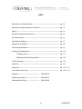
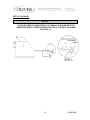
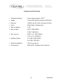
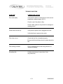
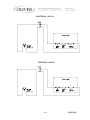
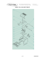
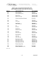
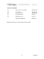
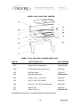
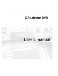
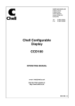
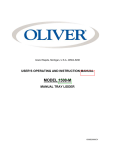
Grand Rapids, Michigan, U.S.A. 49504-5298
USER’S OPERATING AND INSTRUCTION MANUAL
MODEL 1208, 1208-N, & 1208-NLG
HEAT SEALER
MFG DATE: _________________________
MODEL NUMBER: ____________________
SERIAL NUMBER: ____________________
1208S20000CV2
INDEX
Description and Specifications--------------------------------------------- pg. 1-2
Description and Specifications Continued---------------------------------- pg. 1-3
Safety---------------------------------------------------------------------- pg. 1-4
Machine Components and Set Up----------------------------------------- pg. 1-5
Set up Continued---------------------------------------------------------- pg. 1-6
Operating Procedures----------------------------------------------------- pg. 1-7
Adjustment and Quality--------------------------------------------------- pg. 1-8
Technical Specifications-------------------------------------------------- pg. 1-9
Cleaning and Maintenance----------------------------------------------- pg. 1-10
Changing Cutter-------------------------------------------------- pg. 1-11
Replacing and Checking Gaskets--------------------------------
pg. 1-12
Trouble Shooting--------------------------------------------------------- pg. 1-13
Electrical-----------------------------------------------------------------
pg. 1-14
Parts Lists---------------------------------------------------------------- pg. 1-15--1-17
Tray Carrier Parts Lists--------------------------------------------------- pg. 1-18--1-19
Warranty----------------------------------
GEN 050816
Warranty Procedure----------------------- GEN 050817
Returned Parts Policy---------------------
GEN 050818
1-1
1208S20003
DESCRIPTION/SPECIFICATIONS
Description
The Oliver Models 1208, 1208-N, and 1208-NLG Heat Sealers are designed and
manufactured to ensure a user friendly operation of producing film lidded trays with a
cost effective approach.
The manually operated machine operates with a 115 or 230 V.A.C. outlet. The machine
was designed to be a compact to limit the amount of table space needed to operate.
Specifications
Space Requirements, (Shown with Standard Options):
Model 1208 & 1208-N (All Dimensions are Approximate)
Shipping Weight – 22 lbs. (approximate)
Net Weight – 18 lbs. (approximate)
1-2
1208S20003
DESCRIPTION/SPECIFICATIONS CONTINUED
Specifications
Space Requirements, (Shown with Standard Options):
Model 1208-NLG (All Dimensions are Approximate)
Shipping Weight – 24 lbs. (approximate)
Net Weight – 20 lbs. (approximate)
(REV. 12/18/06)
1-3
1208S20003
GENERAL SAFETY INSTRUCTIONS
WARNING
IT IS ESSENTIAL THAT ALL OPERATORS AND MAINTENANCE PERSONNEL
OBSERVE THE FOLLOWING SAFETY PRECAUTIONS. IMPROPER
INSTALLATION, MAINTENANCE, OR OPERATION OF THIS EQUIPMENT
COULD CAUSE SERIOUS INJURY.
1. Read this manual before attempting to operate your heat sealer. Never allow an
untrained person to operate or service this unit.
2. Observe all caution and warning labels affixed to the machine.
3. Always unplug the machine before cleaning or servicing.
4. Use only proper replacement parts.
5. Wear proper, personal, protective, safety equipment if necessary.
6. Keep hands away from moving parts of the machine while it is operating.
7. In addition to these general safety instructions, please follow the more specific safety
instructions provided throughout the rest of this operating and instruction manual.
WARNING
DO NOT USE FOR OTHER THAN ORIGINALLY INTENDED PURPOSE.
1-4
1208S20003
BASIC MACHINE COMPONENTS AND SET UP
Before proceeding further, take a moment to familiarize yourself with the identification of
the machine components as shown in the illustration below.
SET UP
1. Carefully remove the Model 1208 from the box. Check to make sure the order is
complete, and it has not been damaged during shipment.
2. Place the unit in a suitable location which provides an adequate working space.
The location must be sturdy, level, and capable of holding 18lbs. per machine.
3. Remove all packaging materials and shipping restraints such as plastic ties and
tape.
4. Raise the handle to full extension.
5. Place film rod into the center of the roll of film.
6. Place film on the machine, and thread film through the film hold down, as shown
below.
1-5
1208S20003
SET UP CONTINUED
NOTE:
FILM SUPPLIED BY OLIVER PRODUCTS COMPANY IS WOUND WITH THE
ADHEASIVE SIDE IN. FEED FILM FROM THE TOP OF THE ROLL AS SHOWN
IN DETAIL “A”.
1-6
1208S20003
OPERATING PROCEDURES
1. Plug the power cord into a properly grounded outlet. Avoid the use of extension
cords. There is a switch on the cover with a light which will illuminate when on.
NOTE: It should take approximately 15 minutes for the machine to warm up to
operating temperature.
2.
Slide tray carrier out until it stops.
3. Place filled tray in tray carrier. Make sure the food in the tray is not higher than
the flange of the tray
4. Grasp the corners of the film and pull it straight across the tray going a ¼ inch
past the flange of the tray.
5. Push tray carrier in gently until it stops.
6. Pull handle down with both hands until it stops. Hold the handle down for
approximately 2 seconds.
7. Lift the handle to its upright position.
8. Pull tray carrier out.
9. Apply pressure to the film hold down bar with index finger, and with the other
hand gently slide the cutter from one side to the other. The cutter works from
both directions. In addition, the blade works better with a minimal amount of
pressure applied.
10. Remove tray from tray carrier.
11. Repeat steps 4 thru 11
CAUTION
IT IS NOT RECOMMENDED TO LEAVE THE MACHINE ON WHEN IT WILL BE OUT
OF OPERATION FOR AN EXTENDED PERIOD OF TIME.
1-7
1208S20003
ADJUSTMENT AND QUALITY
Your OLIVER Model 1208 was tested at the factory using Oliver trays and film.
NOTE
•
•
THE TEMPERATURE CANNOT BE ADJUSTED BY THE OPERTATOR
THE PRESSURE CANNOT BE ADJUSTED BY THE OPERATOR.
The heater platen temperature is factory set at approximately 300 degrees Fahrenheit.
Contact the Oliver Service Department if you suspect the heated platen temperature is
not correct.
It is necessary to periodically check for a proper seal. This can be done by pull the film
over the empty tray carrier, sealing it like normal and pulling the film. If there is a proper
seal, the pattern on the film should be a complete outline of the edges of the tray.
A poor seal will occur if the product in the tray contaminates the tray flange. Moisture
will have the same affect on the seal. Trays that have irregular flanges or are deformed
also seal poorly. Defective trays should be discarded.
Under different operating conditions, it may be necessary to increase or decrease the
sealing time. This is done by varying the length of time the operating handle is in the
down position. Holding the handle down longer makes the seals stronger. Although a
stronger seal may cause shredding or tearing of the film when removing film from tray.
1-8
1208S20003
TECHNICAL SPECIFICATIONS
•
Temperature Range:
Factory preset to approx. 300° F.
•
Weight:
18 lbs (1208/1208-N) and 20 lbs (1208-NLG)
•
Electrical:
120/230 volts AC (USA) 2/4 Amps ,50-60 Hz
•
Finish:
White Pebble / Stainless steel
•
Max roll diameter:
2” OD
•
Max roll width:
8.875” (1208/1208-N)
10.500” (1208-NLG)
•
Max. tray size:
8.625” x 6.5” (1208/1208-N)
10.25” x 8.5” (1208-NLG)
•
Handle pull down:
15 to 20lb (1208/1208-N)
20 to 30lb (1208-NLG)
•
Dielectric breakdown:
1250 for one second
•
Constructed of:
White HDPE / Stainless steel / Aluminum
1-9
1208S20003
CLEANING AND MAINTENANCE
NOTE
•
These cleaning recommendations are not meant to replace plant standard
manufacturing procedures or regulatory requirements.
•
If the machine has been in operation, allow the unit to cool before cleaning.
•
Tray carrier is NOT recommended for automatic dishwashers
CAUTION
•
CAUTION HOT: The heated platen is HOT! Caution must be used to prevent
injury from heated platen.
WARNING
•
Make sure the unit has been unplugged for a minimum one hour before cleaning.
•
It is important that the surface of the heater platen is kept clean and smooth.
Regularly clean the OLIVER Model 1208 with a mild cleaner and a damp cloth. If
food product comes in contact with the surface of the platen, it tends to burn on
and become hard. This results in an irregular surface on the face of the platen
which can result in poor seals. If this happens, it will be necessary to remove this
contaminate material. When cleaning care must be taken to avoid scratching or
gouging the surface of the platen. DO NOT SCRAPE THE SURFACE OF THE
PLATEN WITH SHARP OBJECTS AND AVOID THE USE OF METAL TOOLS.
The use of plastic or soft-metal scouring pads such as “SCOTCH BRITE” or
“CHORE BOY” provides a safe and effective means of cleaning the platen. Be
sure to wipe all surfaces with a sanitizing agent after cleaning.
WARNING
• If it is necessary to the clean the platen while it is still hot although not recommended,
be sure to use something such as a hot pad glove to protect your skin.
1-10
1208S20003
CLEANING PROCEDURES
1. Remove tray carrier by pushing the carrier in, lifting the tray carrier straight
up, and then pull out.
2. Wipe down tray carrier and gaskets with a standard cleaning solution.
3. Tip the machine up on its side, and then wipe off the heated platen.
4. Wipe sides, top and handle of the machine.
5. Replace tray carrier
CHANGING CUTTER BLADE
1. Remove tray carrier, as described above
2. Use a flat head screw driver to remove one of the screws on either end of the
cutter track
3. Replace old cutter with new
4. Replace and retighten screw
1-11
1208S20003
REPLACING AND CHECKING GASKETS
•
If there are any gouges, cuts or gaps in the gasket, the gasket will have to be
replaced.
•
Be sure to replace all the gaskets not just the piece that is damaged.
•
When reinstalling gaskets, the gasket must be seated all the way down in the
groove.
•
Do not stretch gasket when reinstalling.
•
After the new gaskets are installed, place the tray carrier up side down on a flat
surface and check to see if the newly installed gasket is even.
•
If not even, depress or lift gasket to provide an even heat sealing surface.
•
It is necessary to periodically check for a proper seal. This can be done by pull
the film over the empty tray carrier, sealing it like normal and pulling the film. If
there is a proper seal, the pattern on the film should be a complete outline of the
edges of the tray.
1-12
1208S20003
TROUBLE SHOOTING
SYMPTOM
CORRECTIVE ACTION
Poor seal quality
Verify that the platen is heated and is at the correct
temperature (approximately 300° F)
Check to see if the platen is dirty
Check rubber gasket on tray holder for damaged or
missing pieces
Platen does not heat up
Verify that the power cord is plugged into outlet
Verify that there is power at the outlet
Film does not cut
Check that the film is threaded properly
Be sure the film hold down bar is in place above the
film.
Film sticking to heater
Film is coming off the roll the wrong direction or
improper threading.
Shredding film
Holding sealer down for more than 2 sec.
may cause this.
1-13
1208S20003
ELECTRICAL 1-60-120
ELECTRICS 1-60-230
1-14
1208S20003
MODEL 1208 & 1208-N HEAT SEALER
1-15
1208S20003
MODEL 1208 & 1208-N HEAT SEALER PARTS LISTS
(PART NUMBERS SHOWN IN BOLD ARE FOR 1208-NLG)
ITEM NO
PART DESCRIPTION
PART NUMBER
001
001
Frame Assembly
Frame Assembly (LG)
1208-0001
1208-0001-002
002
002
Spacer-Front
Spacer-Front (LG)
1208-0001-0043
1208-0001-0053
003
Cushion-Gray Silicone Extruded
6516-0020
004
004
Cover
Cover (LG)
1208-0009
1208-0009-002
101
101
Cam-Pusher
Cam-Pusher (LG)
1208-0005
1208-0005-101
102
102
Arm
Arm (LG)
1208-0006
1208-0006-101
105
105
Handle-Arm
Handle-Arm (LG)
1208-0007
1208-0007-001
106
106
Shaft-Cam
Shaft-Cam (LG)
1208-0010
1208-0010-001
107
Ring-Retaining
5840-1280
108
108
Lifter-Cam
Lifter-Cam (LG)
1208-0008
1208-0008-002
501
501
501
501
Plate-Heater (115V)
Plate-Heater (230V)
Plate-Heater (120V LG)
Plate-Heater (230V LG)
1208-0033-1
1208-0033-101
1208-0033-102
1208-0033-103
504
Retainer-Spring Plate
1208-0019
505
505
Spring-Compression
Spring-Compression (.100”)
7014-3106
7015-2200
(REV. 7-8-08)
1-16
1208S20003
PARTS LIST CONTINUED
506
Screw-1/4” DIa. x 3/4" Shoulder
4560-0908-1201
512
512
Cover-Electrical
Cover-Electrical (LG)
1208-0021-002
1208-0021-003
513
Bushing-Strain Relief
5765-1076
514
Switch-Rocker on/off
5757-3313
**
Tray Carrier Components
See Pg. 1-16
FOR SERVICE PARTS CALL OLIVER PRODUCTS @ 800-253-3893
1-17
1208S20003
MODEL 1208 & 1208-N TRAY CARRIER
MODEL 1208 & 1208-N TRAY CARRIER PARTS LISTS
ITEM NO
PART DESCRIPTION
PART NUMBER
201*
Carrier-Tray 3 Compartment
1208-0013-500
202**
Cushion-White Silicone Extruded
6516-0028
203
203
Rod-Film Holder
Rod-Film Holder (LG)
1208-0014
1208-0014-001
204
Screw-10-24 x 1” STST Set
5843-2024
205
Pin-1/4” x 5/8” STST Dowel
5835-6474
206
Pin-3/16” x 1/2” STST Quick Release
5835-7800
207
207
Slitter-T-Slot
Slitter-T-Slot (LG)
1208-0016
1208-0016-002
FOR SERVICE PARTS CALL OLIVER PRODUCTS @ 800-253-3893
1-18
1208S20003
TRAY CARRIER PART LIST CONTINUED
208
Cutter-Slide
5903-5600
209
Stud-10-24 x 1/2” STST Weld
5843-5067
210
Screw-Rnd. Hd. 6/32 x 3/8” STST
5843-5211
211
211
Hold Down-Film
Hold Down-Film (LG)
1208-0012
1208-0012-001
212
212
Tube-Film
Tube-Film
1208-0015
1208-0015-001
* Tray carries do not come with stock units. They are ordered separate and customized
based on the tray that is being used in the sealing operation.
** Cushions differ from tray carrier to tray carrier. The cushion that is used is determined
by the engineer during the design process.
FOR SERVICE PARTS CALL OLIVER PRODUCTS @ 800-253-3893
1-19
1208S20003
WARRANTY
PARTS
Oliver Products Company (Oliver) warrants that if any part of the equipment (other than a
part not manufactured by Oliver) proves to be defective (as defined below) within one year
after shipment, and if Buyer returns the defective part to Oliver within one year, Freight
Prepaid to Oliver’s plant in Grand Rapids, MI, then Oliver, shall, at Oliver’s option, either
repair or replace the defective part, at Oliver’s expense.
LABOR
Oliver further warrants that equipment properly installed in accordance with our special
instructions, which proves to be defective in material or workmanship under normal use
within one (1) year from installation or one (1) year and three (3) months from actual
shipment date, whichever date comes first, will be repaired by Oliver or an Oliver Authorized
Service Dealer, in accordance with Oliver’s published Service Schedule.
For purposes of this warranty, a defective part or defective equipment is a part or equipment
which is found by Oliver to have been defective in materials workmanship, if the defect
materially impairs the value of the equipment to Buyer. Oliver has no obligation as to parts
or components not manufactured by Oliver, but Oliver assigns to Buyer any warranties
made to Oliver by the manufacturer thereof.
This warranty does not apply to:
1. Damage caused by shipping or accident.
2. Damage resulting from improper installation or alteration.
3. Equipment misused, abused, altered, not maintained on a regular basis, operated
carelessly, or used in abnormal conditions.
4. Equipment used in conjunction with products of other manufacturers unless such use is
approved by Oliver Products in writing.
5. Periodic maintenance of equipment, including but not limited to lubrication, replacement
of wear items, and other adjustments required due to installation, set up, or normal wear.
6. Losses or damage resulting from malfunction.
The foregoing warranty is in lieu of all other warranties expressed or implied AND OLIVER
MAKES NO WARRANTY OF MERCHANTABILITY OR FITNESS FOR PURPOSE
REGARDING THE EQUIPMENT COVERED BY THIS WARRANTY. Oliver neither
assumes nor authorizes any person to assume for it any other obligations or liability in
connection with said equipment. OLIVER SHALL NOT BE LIABLE FOR LOSS OF TIME,
INCONVENIENCE, COMMERCIAL LOSS, INCIDENTAL OR CONSEQUENTIAL
DAMAGES.
GEN 050816
WARRANTY PROCEDURE
1. If a problem should occur, either the dealer or the end user must contact the Customer
Service Department and explain the problem.
2. The Customer Service Manager will determine if the warranty will apply to this particular
problem.
3. If the Customer Service Manager approves, a Work Authorization Number will be
generated, and the appropriate service agency will perform the service.
4. The service dealer will then complete an invoice and send it to the Customer Service
Department at Oliver Products Company.
5. The Customer Service Manager of Oliver Products Company will review the invoice and
returned parts, if applicable, and approve for payment.
GEN 050817
RETURNED PARTS POLICY
This policy applies to all parts returned to the factory whether for warranted credit,
replacement, repair or re-stocking.
Oliver Products Company requires that the customer obtain a Return Material Authorization
(RMA) number before returning any part. This number should appear on the shipping label
and inside the shipping carton as well. All parts are to be returned prepaid. Following this
procedure will insure prompt handling of all returned parts.
To obtain an RMA number contact the Repair Parts Deptartment toll free at (800) 253-3893.
Parts returned for re-stocking are subject to a RE-STOCKING CHARGE.
Thank you for your cooperation,
Repair Parts Manager
Oliver Products Company
GEN 050818