1
SYSGEN SC5500
TAPE CONTROLLER
INTERFACE
Applications Manual
SYSGEN, Inc.
47853 Warm Springs Blvd.
Fremont, CA 94539
Phonc: (415) 490·6770
Telex: 4990843
87·01150·01 Rc\,. B
November 1985
Copyright notice
Manual Copyright (C) 1985, SYSGEN, Inc.
All Rights Reserved.
Printed in U.S.A.
SYSGEN
™ is a trademark of SYSGEN, Inc.
lBMR is a registered trademark of International Business Machines Corporation.
SYSGEN, Inc. reserves the right to make changes or improvements to the
equipment, software, and documentation described herein at any time and without
notice.
Every possible effort was made to ensure accuracy in this manual. However,
SYSGEN, Inc. cannot accept responsibility for any manual errors or consequences
resulting from such errors. Unless you receive written permission from SYSGEN,
Inc., you may not reproduce or transmit any part of this document in any form by
any electronic or mechanical means, including photocopying and recording, or by
any information storage and retrieval system.
How to Use This Manual
•••••••••••••••••••••••••••••••••••••••••••••••••• m•••••••••
This manual describes the features and operation of the SYSGEN SC5500 Tape
Controller Interface for IBM PC, XT, AT, and compatible computers. The
interface consists of the SC5500 Tape Controller board and the Software Interface
Module containing the SC5500 control commands. The interface module gives thc
user complete command of tape operations from his system or application
program.
The SC5500 Tape Controller interfaces with an industry-standard QIC-36
cartridge or DCAS cassette streaming tape drive. The interface described in this
manual is the cartridge tape drive. For information about the cassette interface,
please contact SYSGEN Incorporated.
Chapter I discusses the features and operation of the SC5500 Tape Controller
board, including functions of the read/write registers and the tape controller
pulses, jumper selections, and the action of the Programmable Array Logic (PAL).
Summary tables are included for easy reference.
Chapter 2 describes the SYSGEN Software Interface Module, including
subroutine entry points, command protocols for NEAR CALLS in both
ASSEMBL Y and C language, and control commands. An alternate set of FAR
CALL entry points is provided for users of the LATTICE C Large Memory Model.
The chapter includes reference tables on the subroutine entry points and the
control commands.
SC5500 Tape Controller specifications, pin assignments for the SC5500 50-pin
tape drive interface connector, and error codes are provided in the appendixes.
COPYRIGHT (C) SYSGEN, INC. 1985
III
Compliance with FCC Regulations
This equipment generates and uses radio frequency energy and if not installed
and used properly; i.e., in strict accordance with the Owner's Manual, may cause
harmful interference to radio communications. It has been tested and found to
comply with the limits for a Class A computing device pursuant to Subpart J or
Part 15 of FCC Rules, which are designed to provide reasonable protection against
such interference when operated in a commercial environment.
Operation of this equipment in a residential area is likely to cause interference in
which case the user at his own expense will be required to correct the
interference.
Contents
••••••••••••••••••••••••••••••••••••••••••••••••••••••••••••
CHAPTER J SC5500 Tape Controller Board ....................................................................... 1-1
Registers and Control Pulses ................................................................................................. 1-3
Read Operation ...................................................................................................................... 1-6
Write Operation .................................................................................................................... 1-8
Hard Fi]e Mark ...................................................................................................................... 1-9
Diagnostic Opera tion ........................................................................................................... ]-9
Jumper Functions
.................................................................................................................. ]-9
Programmable Array Logic .............................................................................................. ]-11
CHAPTER 2 Software Illter/ace !rlodule ................................................................................ 2- 1
Subrou tines ..................................................................................................................................... 2-2
Calling Protocol ........................................................................................................................... 2-3
IN]TCMO ............................................................................................................................... 2-3
-WAITCMO ............................................................................................................................. 2-4
-GETOAT ................................................................................................................................ 2-5
-PUTOAT ................................................................................................................................ 2-7
-POLLCMO ............................................................................................................................. 2-10
-DORSET................................................................................................................................. 2-1 I
Alternate Entry Points .............................................................................................................. 2-12
Command Description ............................................................................................................... 2-13
Deselect Tape Drive ............................................................................................................. 2-14
Select Tape Drive .................................................................................................................. 2-14
Rewind Tape to BOT .......................................................................................................... 2-]4
Erase Tape Data ..................................................................................................................... 2-]4
Retension Tape ....................................................................................................................... 2-15
Write Tape Data ..................................................................................................................... 2-15
Write Tape File Mark .......................................................................................................... 2-15
Read Data Block .................................................................................................................... 2-15
Read Tape File Mark .......................................................................................................... 2-16
Position to EOT Data .......................................................................................................... 2-]6
Request Sense Bytes ............................................................................................................. 2-17
Request Sta tistics Bytes ...................................................................................................... 2-18
Request Tape Block 10....................................................................................................... 2-19
COPYRIGHT (C) SYSGEN, INC. 1985
v
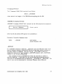
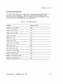
Tape Controller Board
Figure J-J. SC5500 Tape Controller Boards
SC5500 Internal Tape Controller Board
SC5500 External Tape Controller Board
]-2
COPYRIGHT (C) SYSGEN, INC. ] 985
Tape Con/roller Board
Interface with the tape drive is by means of the SC5500 50-pin internal or
external connector. The internal version of this connector interfaces the control
board with a tape drive mounted inside the host computer housing. Pin
assignments for the 50-pin connector are given in Appendix B. Signal definition is
dictated by the tape drive specifications.
REGISTERS AND CONTROL PULSES
The SC5500 write and read registers transfer information between the host
computer and the tape controller. Control pulses, triggered by the host computer,
reset tape error, generate the single-step clock, and initiate read transfer from
tape to computer. Tables 1-1 and 1-2 define the write and read registers,
respectively. Table 1-3 defines the computer-triggered control pulses.
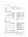
Table 1-1. Write Registers
Name
Address
Function
WTTPINTF*
290 hex
Tape interface
TRO*
TRI*
TR2*
TR3*
GO*
REV*
EEN*
WEN*
Track 0
Track I
Track 2
Track 3
Go
Reverse
Erase enable
Write enable
Bit map:
*Denotes active low level. Single-step mode permits only one DMA
operation; dual-step mode permits two concurrent operations.
COPYRIGHT (C) SYSGEN, INC. ) 985
1·3
Tape Controller Board
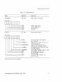
Table 1-1, Write Registers (Continued)
Name
Address
FUDction
CONTROL*
292 hex
Control signals
DMAENO
ENTPWRCNTR
PCDMA3 enable; active high
Tape write counter enable;
active high
File mark enable; active high
Write enable; active high
PCDMAI enable; active high
Tape read gate; active high
Tape read sequencer enable;
active high
Tape interface enable; active_
high
Bit map:
~--
L..-____ FILEMARKEN
L..--------WRITE
L..-___________ DMAEN 1
L..-_ _ _ _ _ _ _ _ TPRDGATE
I.-..------~- TPRDSQEN
L..-_ _ _ _ _ _ _ _ _ _ _ ENTPINTF
MODE
293 hex
Mode register, interrupt
enable
INTEN
TPDIAG
DUAL/SINGLE
Interrupt enable; active high
Diagnostic mode; active high
Active how sets single-step
mode; active high sets
dual-step mode*
Reserved for future
application; switching DMARQ
selection to PC.
Single-step clock enable;
active low enables single-step
clock, disable TPCLK
Drive select; active low
selects IO-mb drive, active
high selects 20/4S-mb drive
Bit map:
17161S1413121110\
I
MODE
CSELSSCLK
CNTSEL
RESERVED
RESERVED
*Denotes active low level. Single-step mode permits only one DMA
operation; dual-step mode permits two concurrent operations.
1-4
COPYRIGHT (C) SYSGEN, INC. 1985
Tape COli/roller Board
Table J-2. Read Registers
Name
Address
FUDction
RDTPINTF*
290 hex
Read tape interface
Bit map:
1..-_ _ _ _ _ _ _
~------------
1..-_ _ _ _ _ _ _ _ _
L..-_ _ _ _ _ _ _ _ _ _ _
RDTPST*
UTH*
LTH*
CIN*
USF*
Upper tape hole
Lower tape hole
Cartridge in
Unsafe
293 hex
Read tape status
TPWDA
Writing tape write data;
active high
Tape error flag; active low
latched signal
Tape read transfer done;
active low latched signal
Filemark block; active high
latched signal
Cartridge change; active high
Interrupt; active low
Internal DMA request I;
active high
Internal DMA request 0;
active high
Bit map:
~--
~----
~-----
TPERRFLG*
TPRDXFDONE*
FILEMARK
" " ' - - - - - - - - CARCHANGE
INT*I
DRQ
~-------L..-_ _ _ _ _ _ _ _
L..-_ _ _ _ _ _ _ _ _ _
DRQO
*Denotes active low level.
COPYRIGHT (C) SYSGEN, INC. 1985
1-5
Tape Controiler Board
Table 1-3. Control Pulses
Name
Address
(hex)
Mode
Function
RSTERR*
291
Write
Resets tape error
RDSTRXF*
291
Read
Starts read transfer from tape to
computer
TPSSCLK*
292
Read
Generates single-step clock when
the clock enable (CSELSSCLK*) is
low.
*Denotes active low level.
READ OPERATION
The read operation is accomplished in the following steps. (Refer to Tables I-I
through 1-3):
1.
Set the mode register (MODE, active high).
2.
Set the tape interface register (WTTPINTF, active Jow).
3.
Set the control register (CONTROL, active low).
a. Enable the DMA (DMAENO and DMAENJ,
active high).
b. Enable the tape read gate (TPRDGATE,
active high).
c. Enable the tape read sequencer (TPRDSQEN,
active high).
d. Enable the read transfer pulse (RDSTRXF*,
active low) to start the read operation.
1-6
COPYRIGHT (C) SYSGEN, INC. 1985
Tape Con/roller Board
In single-step mode (single operation), DMAENO high enables PC DMA signal
PCDRQ3 for a read, write, or read-after-write operation. In dual-step mode (two
concurrent operations), DMAENO high enables PCDRQ3 for a write operation and
DMAEN 1 high enables PCDRQ 1 for a read operation.
COPYRIGHT (C) SYSGEN, INC. 1985
1-7
Tape Controller Board
Read-transfer-done is indicated by an active low latched signal on the tape
read transfer done line (TPRDXFDONE) of the status register and also by an
active high signal on the interrupt enable line (INTEN) of the mode register. To
use the interrupt line to indicate the read done, you must enable INTEN (active
high). Any error condition during read is also indicated on the interrupt line.
Reset pulse RSTERR·, triggered by the host computer, will clear this interrupt.
WRITE OPERATION
The write operation is accomplished in the following steps. (Refer to Tables 1-1
and 1-2):
1.
Set the mode register (MODE, active high).
2.
Set the tape interface register (WTTPINTF, active low).
3.
Set the control register (CONTROL, active low):
a. Enable the DMA (DMAENO and DMAENI,
active high).
b. Enable the tape interface (ENTPINTF,
active high).
c. Enable the write signal (WRITE,
active high).
d. Enable the tape write coun.ter signal
(ENTPWRCNTR, active high).
In single-step mode (single operation), DMAENO high enables PC DMA signal
PCDRQ3 for a read, write, or read-after-write operation. In dual-step mode (two
concurrent operations), DMAENO high enables PCDRQ3 for a write operation and
DMAENI high enables PCDRQI for a read operation.
The write done is indicated by an active high signal on the interrupt enable
line (INTEN) of the mode register.
1-8
COPYRIGHT (C) SYSGEN, INC. 1985
Tape Controller Board
HARD FILE MARK
The hard file mark is written by enabling the FILEMARKEN signal on the
Control register (active high) and writing the data FF hexadecimal. The data FF
is subsequently converted into a unique Group Code Recording (GCR):
00101,00101. During read operation in dual mode, the GCR is decoded as a hard
file mark and FILEMARKEN is enabled on the status line (active high). In dual
mode, the GCR is transferred via Channel 3 and the J.D. is transferred via
Channel O.
DIAGNOSTIC OPERATION
In the diagnostic mode, the LSI chip gives the data AA hexidecimal for read
operation only. The single-step clock is enabled by an active low signal on the
single-step clock enable line (CSELSSCLK) of the mode register. This signal
disables the TPCLK signal and stops the 1 IO-nsee clock. The TPCLK signal is reena bled when the computer triggers the TPSSCLK pulse.
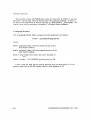
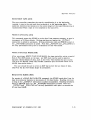
JUMPER FUNCTIONS
Jumper WI selects PC address 290. Jumpers W2 through W4 are only used to test
the four boards simultaneously. Table 1-4 summarizes the jumper functions.
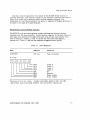
Jumper W5 currently selects IRQ3· (interrupt channel 3). If you want to make
the default IRQ5 (interrupt channel 5), you must change the jumper. On some
versions of the board, you must also cut the trace as shown in Figure 1-2. If
your board does not look like figure 1-2. YOll do not need to cut the trace. JUS! change
the jumper.
COPYRIGHT (C) SYSGEN, INC. 1985
1-9
Tape Controller Board
Table }·4. Jumper Functions
Jumper
Function
WI
Selects PC address 290
W2
Selects PC address 2AO
W3
Selects PC address 2BO
W4
Selects PC address 2CO
W5
Selects IRQ3.
(See Figure 1-2 to select IRQ5.)
Figure }·2. Selecting IRQ5
Jumper
block
A
1·10
B
COPYRIGHT (C) SYSGEN, INC. 1985
Tape Controller Board
PROGRAMMABLE ARRAY LOGIC
Table 1-5 describes the action of the Programmable Aray Logic (PAL). By using
the combinations shown in the table, you can transfer data in dual mode, single
mode, or diagnostic mode. The diagnostic mode is for internal testing only.
Table 1-5. PAL Action
Signal
WRITE
Transfer to PC
SINGLE*/
DUAL
DMAENO
DMAENJ
SC5500
-----.....
PC
ON
Don't
care
ON
OFF
DMARQO
------.
PCDRQ3
OFF
Don't
care
ON
OFF
DMARQI -----....
PCDRQ3
Don't
care
DUAL
OFF
ON
DMARQ3 ------.
PCDRQI
Don't
care
SINGLE*
OFF
ON
DMARQI
----- ....
PCDRQI
*Denotes default.
PAL also transfers the tape, interrupt to PCINT.
COPYRIGHT (C) SYSGEN, INC. 1985
1-1 I
Chapter
2
Software Interface Module
..................................... .....................
~
The Software Interface Module described in this chapter is a highly intelligent
PCDOS/MSDOS rclocatable object module that the user can incorporate in his
system or application program to command the SYSGEN SC5500 Tape Controller.
The interface consisf( of six access subroutines that are callable with ASSEMBLY
language, LATTICE C, and other high-level languages compatible with
LATTICE C.
Note:
Microsoft R C Version 2.XX is fully compatible,
but not Version 3.XX. Users of Version 3 should consult
their user's manual to find out how to achieve compatability.
SUBROUTINES
The Software Interface Module subroutines are summarized in Table 2-1. This
table gives the sequence of execution for data and nondata commands. The
subroutines can be linked directly into the user's application program or
incorporated into a standard DOS device driver.
COPYRIGHT (C) SYSGEN. INC. 1985
2-1
Software Inler face
Table 2-J. Interface Module Subroutines
Subroutine
Function
DORESET
Initialize controller hardware
INITCMD
Start a tape command
GETDAT
Start data transfer, tape to computer memory
PUTDAT
Start data transfer, computer memory to tape
POLLCMD
Check for completion of DMA transfer
WAITCMD
Wait for command to terminate
Command execution is in two or three phases as follows:
Nondata transfer commands (ex., Rewind):
1.
INITCMD
2. -WAITCMD
Data input commands (ex., Read Tape Data):
1.
INITCMD
2. -GETDAT
3. -WAITCMD
Data output commands (ex., Write Tape Data):
1.
INITCMD
2. -PUTDAT
3.
WAITCMD
2-2
COPYRIGHT (C) SYSGEN, INC. 1985
Software Inter face
The subroutines DORESET and POLLCMD are supplemental.
DORESET
initializes the controller hardware, and _POLLCMD checks for complCtion of the
DMA operation.
CALLING PROTOCOL
All calls included in this section are Intel 8088 microprocessor NEAR CALLS.
For users of the LATTICE C Large Memory Model, a special set of FAR CALL
entry points is provided in Table 2-2 (see the following section, "Alternate Entry
Points").
Note that on entry to all the subroutines, DS must be set to the C data segment
DGROUP.
INITCMD
INITCMD starts the command execution and returns control to the caller
immediately, without waiting for a command to terminate. It must be followed by
a call to _GETDAT, _PUTDAT, or _WAITCMD.
An INITCMD call will only return an ERROR if the controller does not
respond properly to the command initiation. In this case the command protocol
should be aborted, since the controller cannot continue.
C Language Protocol
The C language NEAR CALL protocol is as follows:
status = _iuitcmd(cmd_code)
where:
cmd_code = integer specifying the command to execute
status = integer: ·1 for ERROR, anything else for OK.
COPYRIGHT (C) SYSGEN, INC. 1985
2-3
Software Inler face
Specific command codes are described under "Command Description" in this
chapter.
ASSEMBLY Language Protocol
The ASSEMBLY language NEAR CALL protocol has the following stack
arrangement:
Return Address
Stack point
Cmd code
Stack point
+
2
(Only CS, DS, ES, SS and BP registers are unmodified.)
Example of Assembly language usage:
PUSH
CALL
ADD
word ptr cmd_code
initcmd
sp,2
jpush parameter onto stack
jcall routine
jremove parameter from stack
;result returned in AX
WAITCMD
This call waits for an ERROR to occur or for the command in progress to
terminate before returning control to the caller. If an ERROR is returned, the
user should send a Request Sense command to determine the nature of the error.
Request Sense is described under "Command Description" in this chapter.
COPYRIGHT (C) SYSGEN, INC. 1985
SO/llVar(' Illler /aC£'
C Language Protocol
The C language NEAR CALL protocol is a·s follows:
status
= _waltcmdO
where status is an integer: ·1 for ERROR and anything else for OK.
ASSEMBLY Language Protocol
ASSEMBLY language NEAR CALL protocol has the following stack arrangement:
Return Address
Stack point
(Only CS, DS, ES, SS and BP registers are unmodified.)
Example of Assembly language usage:
CALL
_waitcmd
jca)) routine
jresult returned in AX
_GETDAT
If no ERROR condition is detected, GETDAT starts the DMA data input from
tape to computer memory, then returns control to the caller without waiting for
the data transfer to complete. The user can call POLLCMD to check for
completion; however, he must terminate GETDAT properly with WAITCMD,
whether or not he calls _POLLCMD.
This command returns an ERROR only when the controller is unable to
continue operation. In this case, the user should abort the command protocol.
Any error in the operation will be reported by WAITCMD or POLLCMD. The
type of error can be determined by initiating a Request Sense command.
COPYRIGHT (C) SYSGEN, INC. 1985
2-5
Soltware Illter lace
C Language Protocol
_GETDA T has the following C language NEAR CALL protocol:
sta tus
=_getda t(borr ,bseg,n bytes)
where:
boff = unsigned integer with the offset portion of the
data buffer address
bseg = unsigned integer with the segment portion of the
data buffer address
nbytes
c
long integer byte count; must be a multiple of 512
status = integer: -1 for ERROR, anything else for OK.
A zero value for bseg has the special meaning that the data buffer is in the
segment specified by the DS register (default data segment in C).
ASSEMBL Y Language Protocol
The ASSEMBLY language NEAR CALL protocol has the following stack
arrangement:
Return Address
Stack point
Buffer Offset
Stack point
+ 2
Buffer Segment
Stack point
+ 4
(LSW) Nbytes
Stack point
+ 6
(MSW) Nbytes
Stack point
+ 8
(Only CS, DS, ES, SS, and BP registers are unmodified.)
2-6
COPYRIGHT (C) SYSGEN, INC. 1985
Software filler jace
Example of Assembly language usage:
PUSH
word ptr nbytes[2}
imsw of byte count
PUSH
word ptr nbytes[O)
jlsw of byte count
MOV
ax,seg buffer
PUSH
ax
MOV
ax,o(fset buffer
PUSH
ax
;oUset of data buffer
CALL
_getdat
;call routine
ADD
sp,8
jremove parameters from stack
jresult returned in AX
isegment of data buffer
Nole:
If the cmd code specified to the previous INITCMD is either a
Request Sense or Request Statistics command, then 8 bytes will be
transferred, regardless of the value of nbytes.
PUTDAT
If no ERROR condition is detected, PUTDAT initiates DMA data output from
computer memory to tape, then returns control to the caller without waiting for
data transfer to complete. The user can call POLLCMD to check for completion
of the data transfer; however, he must terminate PUTDAT properly with
_WAITCMD, whether or not he calls _POLLCMD.'
COPYRIGHT (C) SYSGEN, INC. 1985
2-7
Software Inter face
This routine returns an ERROR only when the controller is unable to continue
operation. In this case, the user should abort the command protocol. If there is
an error in the operation, it will be reported by -WAITCMD or POLLCMD. The
type of error can be recovered by means of a Request Sense command.
C Language Protocol
The C language NEAR CALL protocol for this command is as follows:
status = _putdat(boff,bseg,nbytes)
where:
boff = unsigned integer with the offset portion of the
data buffer address
bseg = unsigned integer with the segment portion of the
data buffer address
nbyte = long integer byte count; must be a multiple of
512
status = integer: -I for ERROR, anything else for OK
A zero value for bseg has the special meaning that the data buffer is in the
segment specified by the DS register (default data segment in C).
2-8
COPYRIGHT (C) SYSGEN, INC. 1985
Software Illter face'
ASSEMBL Y Language Protocol
The ASSEMBLY language NEAR CALL protocol has the following stack
arrangement:
Return Address
Stack point
Buffer Offset
Stack point + 2
Buffer Segment
Stack point + 4
(LSW) Nbytes
Stack point + 6
(MSW) Nbytes
Stack point
+ 8
(Only CS, DS, ES, SS, and BP registers are unmodified.)
Example of Assembly language usage:
PUSH
word ptr nbytes(2)
;msw of byte count
PUSH
word ptr nbytes(O)
;Isw of byte count
MOV
aX,seg buffer
PUSH
ax
MOV
ax,offset buffer
PUSH
ax
;offset of data buffer
CALL
_putdat
;call routine
ADD
sp,S
;remol'e parameters from stack
;resuJt returned in AX
COPYRIGHT (C) SYSGEN, INC. 1985
;segment of data buffer
2-9
Soflware Inler face
POLLCMD
POLLCMD checks for completion of DMA transfer and termination of nondata
transfer commands. Unlike WAITCMD, it returns control to the caller
immediately to facilitate concurrent operation. This call is for inspection only;
WAITCMD must be called to terminate the command properly.
WAITCMD
must be called even if an ERROR is indicated by the polling.
-
C Language Protocol
The C language NEAR CALL protocol is as follows:
sta tus ... _pollcmdO
where status is an integer: -1 for ERROR, 0 for not done, and anything else for
done.
ASSEMBL Y Language Protocol
The ASSEMBLY language NEAR CALL protocol has the following stack
arrangement:
Return Address
Stack point
(Only CS, DS, ES. SS, and BP registers are unmodified.)
Example of Assembly language usage:
CALL
2-10
jcall routine
jresult returned in AX
COPYRIGHT (C) SYSGEN. INC. 1985
Software Inter face
DORSET
_DORSET initializes the SC5500 Tape Controller hardware. It reports an error
only if controller reset fails and the controller is therefore unable to continue
opera ting,
C Language Protocol
This command has the following C language NEAR CALL protocol:
status = _dorsetO
where status is an integer: -1 for ERROR and anything else for OK.
ASSEMBL Y Language Protocol
The ASSEMBLY language NEAR CALL protocol has the following stack
arrangement:
Return Address
Stack point
(Only CS, DS, ES, SS, and BP registers are unmodifie'd.)
Example of Assembly language usage:
CALL
dorset
COPYRIGHT (C) SYSGEN, INC. 1985
jcall routine
jresult returned in AX
2- I I
Software Inter face
ALTERNATE ENTRY POINTS
Table 2-2 lists alternate entry points so that users of the LATTICE C Large
Memory Model can invoke the subroutines as FAR CALLS. The corresponding
NEAR CALLS are provided for reference.
Table 2-2. Alternate Entry Points
2-12
FAR CALLS
NEAR CALLS
SLRESET
DORESET
SLINITC
- INITCMD
SLGETD
GETDAT
SLPUTD
PUTDAT
SLPOLLC
POLLCMD
SLWAITC
WAITCMD
COPYRIGHT (C) SYSGEN, INC. 1985
Software /II/er/ace
COMMAND DESCRIPTION
The SC5500 Tape Controller recognizes the commands summarized in Table 2-3.
The data transfer commands -- Tape Data, Write Tape Data, Request Sense,
Request Statistics, and Request ID -- have special protocol requirements, which
are discussed under "Calling Protocol" in this chapter.
Table 2-3. SCSSOO Commands
COUDaQd
Address (hex)
DESELECT TAPE DRIVE
OOH
SELECT TAPE DRIVE
OIH
REWIND TAPE TO BOT
21H
ERASE TAPE DATA
22H
RETENSION TAPE
24H
WRITE TAPE DATA
40H
WRITE TAPE FILE MARK
60H
READ TAPE DATA
BOH
READ TAPE FILE MARK
AOH
POSITION TO EOT DATA
A3H
REQUEST SENSE BYTES
COH
REQUEST STATISTICS BYTES
CiH
REQUEST TAPE BLOCK ID
C2H
COPYRIGHT (C) SYSGEN, INC. 1985
2-13
Software Inter face
DESELECT TAPE DRIVE (OOH)
After receiving this command, the SC5500 Tape Controller removes the tape drive
selection signal. On most tape drives, the drive selection light switches off.
When the drive has been deselected, the tape controller cannot sense tape
removal. But it proceeds as if the tape were changed when the drive is reselected
with SELECT TAPE DRIVE.
SELECT TAPE DRIVE (OIH)
This command causes the SCS500 Tape Controller to activate the drive selection
signal. On most tape drives, the drive selection indicator light switches on. The
tape drive must be selected before any tape operation can be performed.
REWIND TAPE TO BOT (21H)
Upon receiving this command, the SCS500 Tape Controller positions the tape to
the beginning (BOT). When a tape is inserted in the tape drive, a REWIND TAPE
TO BOT command must be received before any tape read or write operation can
be performed.
ERASE TAPE DATA (22H)
When it receives an ERASE TAPE DATA command, the SCSSOO removes all data
from the tape by writing an END OF DATA MARK at the beginning of the tape.
The data is not actually erased, but the controller has no means of recovering it.
2-14
COPYRIGHT (C) SYSGEN, INC. 1985
Soflware hIler face
RETENSION TAPE (14H)
The tape controller retensions the tape by repositioning it to the beginning,
running it once to the end, and then reversing it to the beginning again. This
operation restores even tension over the entire length of the tape. Retensioning is
recommended when a tape is first installed in the tape drive.
WRITE TAPE DATA (40H)
This command causes the SCSSOO to write data from computer memory to tape in
increments of 512-byte blocks. Writing continues as long as the PUTDAT
subroutine is called in succession. Writing terminates when an ERROR occurs or
the WAITCMD subroutine is called. Note that PUTDAT and POLLCMD arc
the Only permissable calls prior to termination ofthis write mode:-
WRITE TAPE FILE MARK (60H)
After receiving a WRITE TAPE FILE MARK, the tape controller writes a special
End-of -File (EOF) mark on the tape. An EOF mark can be used to separa te
logically related blocks of data, such as text files. This enables the user to skip
files with the READ TAPE FILE MARK command (See the READ TAPE FILE
MARK description below.)
The user should be sure to write an EOF mark after the last block of data,
otherwise the last few blocks might be unreadable.
READ DATA BLOCK (SOH)
On receipt of a READ DATA BLOCK command, the SC5S00 reads data from the
tape into computer memory in increments of S12-byte blocks. Reading continues
as long as the GETDA T subroutine is called in succession. Reading terminates
when an ERROR occurs or the WAITCMD subroutine is called. Note that
GETDAT and POLLCMD arethe only permissible calls prior to termination
of this Read Mode.
-
-
COPYRIGHT (C) SYSGEN, INC. 1985
2·15
Software Inter face
An EOF ERROR is sometimes generated immediately after the controller reads
the last data block before a file mark. However, the last data block is always
transferred in its entirety before the ERROR is signaled.
READ TAPE DATA commands received after the controller has reached EOF
will generate more EOF ERROR conditions. The only way to pass over a file
mark is to send a READ TAPE FILE MARK command.
READ TAPE FILE MARK (AOH)
A READ TAPE FILE MARK. permits the tape controller to skip from file to file.
After receiving this command, the controller skips over data blocks until it
reaches the next EOF mark. Then it passes over the file mark to the first block
of da ta it encoun ters (beginning of the nex t file).
POSITION TO EOT DATA (A3H)
This command sends the tape controller to the last recorded block on the tape,
which must be an EOT File Mark. Additional data may be written on the tape
when the controller is at EOT.
This command must be sent before a WRITE TAPE DATA or WRITE TAPE
FILE MARK, unless the previous command was a WRITE TAPE DATA or WRITE
TAPE FILE MARK.
The number of File Marks encountered can be obtained from the Block Count
returned by a REQUEST SENSE BYTE command. To obtain the File Mark count,
the user must clear the Block Count to zero with a REWIND or REQUEST SENSE
command before sending the POSITION TO EOT DATA command.
2·16
COPYRIGHT (C) SYSGEN, INC. 1985
Software Inter jac'('
REQUEST SENSE BYTES (COl-I)
The REQUEST SENSE BYTES command must be sent immediately after an
ERROR occurs. Upon receiving this command, the SC5500 sends eight bytes of
sense da ta to the buffer. The sense data contains the error code and other
information, as described below. Error codes are listed in Appendix D.
Immediately after receiving the REQUEST SENSE BYTES command, the tape
controller clears the error code and sets the cumulative block count to zero.
A REQUEST SENSE BYTES command can also be sent when no ERROR has
occurred. While the error code will be' zero, the other fields will contain vatld
status information.
The sense bytes are arranged as follows:
Error Code
Buffer
+
MSB Block Count
Buffer
+
Block Count
Buffer
+
2
LSB Block Count
Buffer
+
3
Status Bits
Buffer
+
4
(reserved)
Buffer
+
5
(reserved)
Buffer
+
6
(reserved)
Buffer
+
7
0
Status Bits are arranged as follows:
where Bit 7 is TAPE CHANGED (no read/write possible before rewind), and Bits
6 to 0 are reserved.
COPYRIGHT (C) SYSGEN, INC. 1985
2·17
Software Inter face
Block Count is a cumulative count of blocks that were successfully read or
written. This count can be used to determine how many blocks were processed
before a given ERROR occurred. Note that during a POSITION TO END OF
DATA command, the Block Count reflects the number of file marks encountered,
not the number of data blocks.
REQUEST STATISTICS BYTES (CIH)
When the tape controller receives this command, it sends eight bytes of statistics
data to the buffer and then clears the count. The statistics data accumulates
until the next command is received.
The statistical bytes are arranged as follows:
MSB Reread Count
Buffer
+
LSB Reread Count
Buffer
+
MSB Rewrite Count
Buffer
+
2
LSB Rewrite Count
Buffer
+
3
MSB Overrun Count
Buffer
+
4
LSB Overrun Count
Buffer
+
5
MSB Underrun Count
Buffer
+
6
LSB Underrun Count
Buffer
+
7
0
Reread Count is the total number of read retries in tape read operations.
2·18
COPYRIGHT (C) SYSGEN, INC. 1985
Software Inter face
Rewrite Count is the total number of data block rewrites in response to an ECC
error in the read-after-write process during tape write operations.
Overrun Count is the total number of times transmission of data from the tape
was halted because the controller did not receive a request for data from the host
software.
Underrun Count is the total number of times the tape was stopped and backed
up over a blank space because the host software failed to transmit data for a
prolonged period of time.
REQUEST TAPE BLOCK ID (C2H)
When the tape controller receives this command, it sends to the buffer four bytes
of Tape Block ID and the first four bytes of Block Data from the last successfully
processed tape block. These eight bytes are arranged as follows:
Track Address
Buffer
+
Control Block Address
Buffer
+
Block Address
Buffer
+
LSB Block Address
Buffer
+ 3
Data Byte 0
Buffer
+ 4
Data Byte
1
Buffer
+ 5
Data Byte 2
Buffer
+ 6
Data Byte 3
Buffer
+
COPYRIGHT (C) SYSGEN, INC. 1985
0
2
7
2-19
Software Inler face
The Track Address is 0 for the first track, 1 for the second track, and so on.
The Control Nibble is 0 for a Data Block and I for a File Mark or End of Data
Mark.
The 20-bit Block Address is 0 for the first block on the tape, 1 for the second
block, and so on. Each block on the tape (data or control block) has a unique
block address.
For control blocks (File or End of Data Mark), Data Byte 0 specifics the total
number of tracks on the tape drive. Data Byte 1 is a 3 for a File Mark and a 2
for an End of Data Mark.
Detailed descriptions of these bytes can be found in any QIC-24 reference
document.
2-20
COPYRIGHT (C) SYSGEN, INC. 1985
Appendix
A
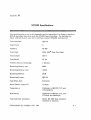
SC5500 Specifications
•••••••••••••••••••••••••••••••••••••••••••••••••••••••••••••
The specifications given in this appendix are for operation of an industry-standard
QIC-36 cartridge tape drive with the SC5500 Tape Controller. For information
about a DCAS cassette tape drive interface, contact SYSGEN Incorporated.
Tape Interface:
QIC-36
Tape Track:
9
Capacity:
60 MB
Tape Used:
600A (3M R Data Cartridge)
Tape Length:
600 ft
Tape Speed:
90 ips
Transfer Rate at Streaming:
5 mb/min
Recording Density, bpi:
8000
Recording Density, ftpi:
10000
Recording Method:
GCR
Recording Format:
QIC·24
Tape Block Size:
512 bytes
Power Drawn from +5V:
1.0 Amp
Temperature:
Conforms to IBM PC, XT, and
AT standards.
Dimensions:
Conforms to IBM PC, XT, and
AT short slot standards
Tape Interface Connector:
SO-pin 3M 3596 male connector
(internal or external)
COPYRIGHT (C) SYSGEN, INC. 1985
A-I
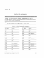
Appendix
B
Interface Pin' Assignments
•••••••••••••••••••••••••••••••••••••••••••••••••••••••••••••
Table B-J gives the SC5500 50-pin connector pin assignments for a QIC-36
cartridge tape drive interface. For information about the DCAS cassette tape drivc
interfacc, contact SYSGEN Incorporated.
Note:
All odd-numbered pins are GND except 15,17,19, and 21.
Table B-l. 50-Pin Connector Pin Assignments
Pin number
Signal
Pin number
Signal
JT-2
GO
JT-28
UTH
JT-4
REV
JT-30
LTH
JT-6
TR3
JT-32
Not connected
JT-8
TR2
JT-34
CIN
JT-IO
TRI
JT-36
USF
JT-12
TRO
JT-38
Not connected
JT-14
RST
JT-40
WDA
JT-15
JT-16
JT-17
JT-42
WDA+
Not connected
JT-44
Not connected
JT-20
Not connected
JT-46
Not connected
JT-22
DSO
JT-48
WEN
JT-24
HC
JT-50
EEN
JT-26
RDP
COPYRIGHT (C) SYSGEN, INC. 1985
B-1
Appendix
C
SC5500 Error Codes
•••••••••••••••••••••••••••••••••••••••••••••••••••••••••••••
Table C-l lists the error codes returned by Request Sense.
Table C-l. SCSSOO Error Codes
Error
Code
(hex)
Undefined command
20
An undefined command code was
specified.
Escessive rewrite
40
More than 16 retries failed in attempt
to write a single data block.
Tape write protected
41
A write operation was attempted on a
read-only tape.
Tape not inserted
42
Cartridge not installed.
Tape full
43
Read or write operation failed because
the end of tape was reached before the
operation completed.
Mission block detected
44
Operation failed because next block is
missing, according to sequence number
of blocks being read. This error can
occur even in a tape positioning
command.
COPYRIGHT (C) SYSGEN. INC. 1985
Descript ion
C-l
Error Codes
Table C-l. SC5500 Error Codes (Continued)
Error
Code
(hex)
Description
Missing BOT/EDT
hole detected
45
Controller failed to detect expected
BOT and EDT hole.
End of data
46
Normal end of tape reached; tape is
positioned for appending.
EOF Mark detected
48
Next block on tape is a file mark,
which can be passed only with a Read
Tape File Mark command. Use Request
Sense to determine number of data
blocks actually transferred.--
Parity error during
command
49
SCSI bus parity error was detected
during execution of the command.
Tape change dtected
4A
The operation can't be performed
unitl rewind/erase/retention is done.
Controller failure
4B
Controller rejected command and is in
unknown state. Call _DORESET, then
rewind tape.
Timeout error
4C
Controller found abnormal length of
blank tape or did not respond within
expected time. (In the latter case,
the tape changed flag will be set.)
Note that an entirely blank tape
immediately following a file mark will
usually return error 46h, not 4Ch.
Unrecognized
control block
4F
Control block other than a Tape File
Mark or EOT Data Mark was read. Tape
may have been written by a different
type of controller.
C-2
COPYRIGHT (C) SYSGEN, INC. 1985