1
Windows CE 6.0
For
BCT RE1
User Guide
Document Reference: Windows CE User Guide
Document Issue: 1.02
Contents
Introduction ............................................................................................................................................ 3
Windows CE 6.0 initialisation and booting overview ......................................................................... 3
Development tool installation ................................................................................................................ 7
Software development ......................................................................................................................... 11
System and Development tools ............................................................................................................ 18
Registry Settings................................................................................................................................ 18
Regedit .............................................................................................................................................. 18
Touch Screen Calibration .................................................................................................................. 19
Visual Studio 2005 Remote Tools ..................................................................................................... 19
RE1 Hardware API Libraries .................................................................................................................. 20
SMBUS API ........................................................................................................................................ 20
LCD Brightness API ............................................................................................................................ 24
GPIO API ............................................................................................................................................ 26
Watchdog API.................................................................................................................................... 31
System Reset ..................................................................................................................................... 33
Appendix A – Windows CE components included in the generic Windows CE image for RE1 ............. 34
Introduction
Introduction
The content of this document provides all the necessary information required to get started with
application development under Windows CE 6.0 for the RE1 platform. It covers:
An overview of the Windows CE 6.0 Boot Process
Peripheral support included in Windows CE 6.0
How to install the tools necessary to develop applications that run under Windows CE 6.0
How to start developing applications
How to use the Hardware API functions supported under RE1
Windows CE 6.0 initialisation and booting overview
The RE1 boot process begins with the execution of a Windows CE boot loader. The boot loader
which is configurable using the RE1 USB device port in conjunction with accompanying desktop
configuration utility performs the following initialisation steps:
Setup initial processor registers
Test for configuration mode or normal Windows CE boot
Setup LCD display and show a custom splash screen
Locate a Windows CE 6.0 image
Boot Windows CE 6.0 Image
The boot loader can be used for updating Windows CE images, Splash screens and even the boot
loader itself. The boot loader is also used to enable or disable peripherals, and configure the
required LCD panel connected to a BCT RE1. The RISC engine supports booting from either onboard
NOR flash or over Ethernet using Windows KITL. Again the boot source is selectable using the boot
loader configuration utility. For full details on configuring the boot loader over USB using the
desktop configuration utility please see the document, “RE1 Single Board Computer User Guide”.
Windows CE 6.0 follows the standard boot process except drivers are configured to dynamically load
dependent on their configuration in the boot loader. If the Windows CE image supports the hive
based registry, the registry is restored from SD Card media during boot. This allows the OS to persist
registry settings through a cold boot.
Page 3
Introduction
Windows CE 6.0 Peripheral Support
The optional generic Windows CE 6.0 image included with an RE1 features support for the following
on-board peripherals.
USB Host
The BCT RE1 features support for an OHCI compatible USB host. Operating system support for HID,
and Mass storage devices is included in the image.
USB Device
In Windows CE the USB device port is implemented as a Microsoft ActiveSync device. Using
ActiveSync 4.5 or greater, it is possible to debug and deploy applications using Visual Studio, as well
as view the internal RISC engine files system in an explorer style interface.
GPIO, IRDA, and I2S
The Windows CE GPIO driver supports up to a maximum of 12 separate pins, all configurable as
either inputs or outputs. Two GPIO pins are mutually exclusive with the IRDA port, and three pins are
mutually exclusive with the I2S peripheral. The pins available to the GPIO driver are dynamically
configured based on if the IRDA driver and I2S driver are enabled. By default the IRDA and I2S
peripherals are disabled in the boot loader so all 12 GPIO pins are available
The IRDA driver is configured to use COM6 when enabled and can be accessed in the same way as
a serial port. Testing for COM6 being present in the system is a method of a custom application
testing if the IRDA port is enabled.
At time of writing, there is no I2S support implemented in the Windows CE image. Contact Blue Chip
Technology sales for details.
Real Time Clock
The BCT RE1 includes a battery backed real time clock. This allows the system time to be
remembered through a cold boot. Calls to either SetSystemTime() or SetLocalTime() automatically
cause the new time to be saving into the battery backed clock.
Serial Ports
Two RS232 ports and one RS422 / 485 port are exposed as standard COM ports in Windows CE.
Please see the following table for details of how each physical port is mapped in Windows CE.
Header
P11 RS422 / 485
P11 RS232
P10
Signal Type
RS422 / 485
RS232
RS232
Control Lines
No
No
Yes
Windows CE COM port
COM1
COM2 (When not in kernel debugging mode )
COM3
Page 4
Introduction
COM2 has a dual purpose in Windows CE. It can be configured as either a Windows CE standard
COM port available to applications or as a kernel debug port useful during OS low level development.
When configured for kernel debug, COM2 is unavailable for application development and is
configured for 115200 baud, 8 data bits, 1 stop bit, and no parity. Please see, “RE1 Single Board
Computer User Guide” for details on configuring this port using the configuration utility.
From Windows CE 6.0 BSP 1.02, the transmit line of the RS422/485 interface is software controllable
to be enabled or disabled by using the DTR control line. When DTR is enabled the TX line is enabled.
When DTR is disabled the TX line is disabled.
Backlight control
A sample brightness control application is included in the Windows CE image to allow the brightness
to be easily changed using the control panel in Windows Explorer. The sample application is included
as source with the Windows CE SDK to demonstrate how to change the brightness using a custom
application. To try the sample LCD Brightness application, navigate to the control panel and double
click on „LCD Brightness‟.
The backlight is also configurable in the “Display Properties” dialogue to allow the screen to be
automatically dimmed after a set amount of time. This feature is useful for power saving when the
device is not in use. Only the external power idle mode is implemented. In the below screen shot the
device is configured to automatically dim the backlight after 2 minutes of inactivity.
Page 5
Introduction
SD Card
RE1 includes a Micro SD card interface which confirms to specification version 1.1 and supports
cards up to 4GB in size. Note: SDHC cards are not supported at this time.
Windows CE optionally includes hive registry support on the SD Card which allows registry settings to
be persisted through a cold boot. If an SD card is used to hold the hive registry, the SD card becomes
none removable and the must be inserted from system start-up.
Other Peripherals
The Windows CE 6.0 has support for, 10/100 Ethernet, stylus touch screen, and AC97 Audio, all of
which are implemented as standard OS components.
Watchdog and I2C support is also provided in the form of API‟s.
Page 6
Installation
Development tool installation
Application development targeting Windows CE 6 for RE1 requires Microsoft Visual Studio 2005 SP1,
Microsoft Active sync 4.5 or greater, and the RE1 software development kit. The version of Visual
Studio 2005 chosen must support smart device development. Ensure that Visual studio is fully
installed along with active sync before following the steps below to install the BCT RE1 SDK.
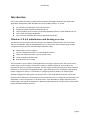
1. Launch the RE1 SDK installer file from the support CD
2. Click next
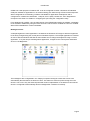
3.
Accept the licence agreement and click next
Page 7
Installation
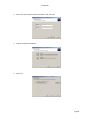
4.
Enter user and company name information and click next
5.
Choose complete installation
6.
Click next
Page 8
Installation
7.
Click install
8.
After the installation completes click the “Finish” button
9.
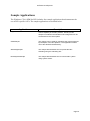
The installation of the BCT RE1 SDK is now complete.
By default the RE1 SDK installs to location: C:\Program Files\Windows CE
Tools\wce600\BCTRE1CE6SDKGeneric. In this location the following folders will be copied.
Folder
Include
Description
This folder holds all the header files required to build an application for
the RE1 platform
Lib
This folder holds all the library files required to build an application for
the RE1 platform
Sample_applications This folder holds some sample applications that can be used as
references while creating applications for RE1. The examples
demonstrate how to interface to the RE1 hardware libraries.
Page 9
Software Development
Sample Applications
The Windows CE 6.0 SDK for RE1 includes four sample applications that demonstrate the
use of RE1 specific API’s. The sample applications are detailed below.
Application
Description
BrightnessController
This sample can be used for evaluating the brightness
control capability of the RE1 platform. A binary of this
sample is included in the Windows CE 6 image and can be
accessed from the control panel.
GPIOSample
This sample can be used for evaluating the general purpose
input/outputs of the RE1 platform. This application makes
use of the GPIOAPI.dll API library.
WatchdogSample
This sample demonstrates how to operate the RE1
watchdog using the watchdog API.
ResetSystemSample
This sample demonstrates how to reset an RE1 system
using system events.
Page 10
Software Development
Software development
This section describes how to create an RE1 Windows CE 6.0 application using the SDK and deploy
the application to the RE1 device using Microsoft ActiveSync over USB. The sample application
created will demonstrate how to use the RE1 GPIOapi to manipulate the GPIO bits.
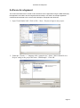
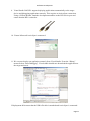
1. Open Visual Studio 2005. Click on File ->New ->Project to begin a new project.
2. Under the “Visual C++” language click “smart device”. Select “Win32 Smart Device
Project” and give the project the name “GPIOSample”. Click OK
Page 11
Software Development
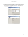
3. The smart device project wizard should now start. Click next to begin. The RE1 SDK
installed in the previous section should now be populated in the “Installed SDKs” list.
Arrange the list boxes so that “BCTRE1CE6SDKGeneric” is the only SDK in the
“Selected SDK’s” list. Click Next.
4. Select console application from the “Application type” selection box and click finish.
Page 12
Software Development
5. Modify the GPIOSample.cpp file to include the following code:
#include "stdafx.h"
#include <windows.h>
#include <commctrl.h>
#include <gpio.h>
int _tmain(int argc, TCHAR *argv[], TCHAR *envp[])
{
DWORD dwReturnCode;
DWORD dwOption = 0;
DWORD dwValue;
DWORD dwBitMap;
WORD wValue;
BOOL iValue;
printf("BCT RE1 GPIO sample application V1.00\n");
while(1)
{
fflush(stdin);
printf("\n\t1) Read PORT\n");
printf("\t2) Write a WORD to PORT\n");
printf("\t3) Set Pin directions\n");
printf("\t4) Get bit\n");
printf("\t5) Set bit\n");
printf("\t6) Exit\n");
printf("\t\tPlease enter an Option(1-6)");
scanf_s("%d", &dwOption);
fflush(stdin);
if(dwOption == 1)
{
printf("\n\nReading Port....\n\t");
dwReturnCode = BCTReadGPIOPort(&wValue);
if(dwReturnCode != GPIO_OK)
{
printf("Failed to read byte with error code: %d\n",
dwReturnCode);
}
else
{
printf("Read value %.4xh\n", wValue);
}
printf("\n");
}
else if(dwOption == 2)
{
printf("\n\nPlease enter the byte to write (HEX): ");
scanf_s("%x", &dwValue);
printf("\n\nWriting Port: %.4xh\n\t", (WORD) dwValue);
dwReturnCode = BCTWriteGPIOPort((WORD) dwValue);
if(dwReturnCode != GPIO_OK)
{
printf("Failed to write byte with error code: %d\n",
dwReturnCode);
}
else
{
printf("Byte written\n");
}
printf("\n");
}
else if(dwOption == 3)
{
printf("\n\nPlease enter a bitmap for pin Directions (HEX): ");
scanf_s("%x", &dwBitMap);
printf("\n\nWriting Port directions: %.2xh\n\t", (WORD) dwBitMap);
dwReturnCode = BCTSetGPIOPinDirection((WORD) dwBitMap);
if(dwReturnCode != GPIO_OK)
{
printf("Failed to set pin directions with error code: %d\n",
dwReturnCode);
}
Page 13
Software Development
else
{
printf("Bit directions written\n");
}
printf("\n");
}
else if(dwOption == 4)
{
printf("\n\nPlease enter which bit value to read (0-11): ");
scanf_s("%d", &dwBitMap);
printf("\n\nReading bit: %d\n\t", (BYTE)dwBitMap);
dwReturnCode = BCTGetGPIOBit((BYTE) dwBitMap, &iValue);
if(dwReturnCode != GPIO_OK)
{
printf("Failed to read bit with error code: %d\n",
dwReturnCode);
}
else
{
printf("Read bit value: %d\n", iValue);
}
printf("\n");
}
else if(dwOption == 5)
{
printf("\n\nPlease enter which bit value to write (0-11): ");
scanf_s("%d", &dwBitMap);
printf("\n\nPlease enter 1 to set or 0 to clear: ");
scanf_s("%d", &dwValue);
if(dwValue > 1)
{
dwValue = 1;
}
if(dwValue < 0)
{
dwValue = 0;
}
printf("\nWriting bit: %d with Value: %d\n\t", (BYTE)dwBitMap,(BOOL)
dwValue);
dwReturnCode = BCTSetGPIOBit((BYTE) dwBitMap,(BOOL) dwValue);
if(dwReturnCode != GPIO_OK)
{
printf("Failed: %d\n", dwReturnCode);
}
else
{
printf("\nBit Written\n");
}
printf("\n");
}
else if(dwOption == 6)
{
break;
}
else
{
printf("\nInvalid Option\n");
}
}
exit(0);
}
Page 14
Software Development
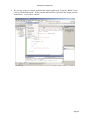
6. As this application is using functions exported by the GPIOAPI library we need to link
this project to the file “GPIOAPI.lib”. From the “Project” menu click properties.
7. Under “Configuration Properties -> Linker -> Input”, add “GPIOAPI.lib” to the
“Additional dependencies”, and click OK.
Page 15
Software Development
8. We are now ready to compile and build the sample application. From the “Build” menu
click on “Rebuild Solution”. If the compile and build was successful the output window
should state “1 succeeded, 0 failed”.
Page 16
Software Development
9. Visual Studio 2005 SP1 supports deploying applications automatically to the target
device and debugging applications remotely. This requires an ActiveSync connection.
Using a USB A/B cable, attach the development machine to the RE1 device port and
ensure that the RE1 is turned on.
10. Ensure Microsoft ActiveSync is connected.
11. We can now deploy our application remotely from Visual Studio. From the “Debug”
menu click on “Start Debugging”. Visual studio should now download the application to
the target and run it.
If deployment fails ensure that the USB A/B cable is attached and ActiveSync is connected.
Page 17
System & Development Tools
System and Development tools
Registry Settings
Windows CE 6.0 for RE1 optionally comes with hive based registry support. This allows
registry settings to be persisted through a cold boot. The Registry Settings utility, accessible
from the system control panel can be used to set how often the volatile registry is backed up
to solid state media, and also perform manual commits. It is possible for a custom application
to manage the persisting the hive registry using the Windows API function
“RegFlushKey()”. In the event that a registry change makes the system unusable, a
factory reset will force the registry to be restored to its default state on next boot. Refer
to the RE1 user manual for details on how to achive this.
Regedit
Windows CE 6.0 for RE1 comes with a built in registry editor in the style of the standard
Windows registry editor. To access it load “regedit” from either the command prompt or Run
menu.
Page 18
System & Development Tools
Touch Screen Calibration
The touch screen can be calibrated using the built in calibration utility. To access it open the
“Stylus Properties” window from the system control panel.
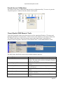
Visual Studio 2005 Remote Tools
Visual 2005 includes remote tools that can be used for managing Windows CE images and
debugging Windows CE applications. All the remote tools require an ActiveSync connection.
The remote tools must be run from the start menu rather than within Visual Studio at
location: Start->Programs->Microsoft Visual Studio 2005->Visual Studio Remote Tools.
The table below details the remote tools available and their purpose:
Remote Tool
Remote File Viewer
Remote Registry Editor
Remote Heap Walker
Remote Spy
Remote Process Viewer
Remote Zoom In
Purpose
Used to browse a remote CE device for files and
folders. The same can be achieved using the Explore
option in ActiveSync.
Used to remotely view and edit a Windows CE
registry
Used to remotely view the memory allocation (heap)
on a CE device
Used to remotely view Windows/Messages on a CE
device
Used to remotely view processes running on a
Windows CE device
Used to retreive a current snap shot of a CE device
desktop
Page 19
Hardware API libraries
RE1 Hardware API Libraries
SMBUS API
The SMBUSAPI is provided to give developers a simple mechanism for accessing devices
attached the RE1 SMBUS compatible bus. The four SMBUSAPI functions provided are
detailed over the next pages.
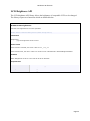
BCTSmbusWriteByte
Sends a command, and writes a byte of data to a device on the SMBUS.
DWORD WINAPI BCTSmbusWriteByte (BYTE bDeviceAddress, BYTE bCommand, BYTE bData);
Parameters
bDeviceAddress
[in] The slave address on the SMBUS to send the command to
bCommand
[in] The SMBUS command identifier
bData
[in] A byte of data to pass in with the command. For commands that do not require any data
be passed in, set this value to 0x00
Return Value
If the function succeeds, the return value is SMBUS_OK.
If the function fails, the return value is a nonzero error code defined in SMBUS.h.
Remarks
As the SMBUS architecture is a two wire interface it operates on a “first come first served” bases. For
this reason the driver also operates in the same way and limits access to its functions to one process at
a time. If the SMBUS is accessed while already in use the error code
SMBUS_DRIVER_LOCKED_BY_OTHER_PROCESS will be returned and is normal. The application
should wait for an undefined period before retrying.
Requirements
Header
Declared in SMBUS.h
Library
Use SMBUSAPI.lib.
DLL
Requires SMBUSAPI.dll.
Page 20
Hardware API libraries
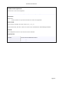
BCTSmbusReadByte
Sends a command, and reads a byte of data from a device on the SMBUS.
DWORD WINAPI BCTSmbusReadByte (BYTE bDeviceAddress, BYTE bCommand, PBYTE pbData);
Parameters
bDeviceAddress
[in] The slave address on the SMBUS to send the command to
bCommand
[in] The SMBUS command identifier
pbData
[out] A pointer to an 8 bit value to hold the data returned
Return Value
If the function succeeds, the return value is SMBUS_OK.
If the function fails, the return value is a nonzero error code defined in SMBUS.h.
Remarks
As the SMBUS architecture is a two wire interface it operates on a “first come first served” bases. For
this reason the driver also operates in the same way and limits access to its functions to one process at
a time. If the SMBUS is accessed while already in use the error code
SMBUS_DRIVER_LOCKED_BY_OTHER_PROCESS will be returned and is normal. The application
should wait for an undefined period before retrying.
Requirements
Header
Declared in SMBUS.h
Library
Use SMBUSAPI.lib.
DLL
Requires SMBUSAPI.dll.
Page 21
Hardware API libraries
BCTSmbusBufferedWrite
Sends a command, and writes up to 16 bytes of data.
DWORD WINAPI BCTSmbusBufferedWrite(BYTE bDeviceAddress, BYTE bCommand, BYTE
bdata[], BYTE bBytesToWrite);
Parameters
bDeviceAddress
[in] The slave address on the SMBUS to send the command to
bCommand
[in] The SMBUS command identifier
bdata
[in] An pointer to an array of bytes to write
bBytesToWrite [in] The number of bytes to write
Return Value
If the function succeeds, the return value is SMBUS_OK.
If the function fails, the return value is a nonzero error code defined in SMBUS.h.
Remarks
As the SMBUS architecture is a two wire interface it operates on a “first come first served” bases. For
this reason the driver also operates in the same way and limits access to its functions to one process at
a time. If the SMBUS is accessed while already in use the error code
SMBUS_DRIVER_LOCKED_BY_OTHER_PROCESS will be returned and is normal. The application
should wait for an undefined period before retrying. This function supports sending a maximum of 16
bytes at a time. This function can also be used for SMBUS quick writes, by setting the bBytesToWrite to
0. This will cause the function to send the command without a data phase.
Requirements
Header
Declared in SMBUS.h
Library
Use SMBUSAPI.lib.
DLL
Requires SMBUSAPI.dll.
Page 22
Hardware API libraries
BCTSmbusBufferedRead
Sends a command, and reads up to 16 bytes of data.
DWORD WINAPI BCTSmbusBufferedRead(BYTE bDeviceAddress, BYTE bCommand, BYTE bdata[],
BYTE bBytesToRead);
Parameters
bDeviceAddress
[in] The slave address on the SMBUS to send the command to
bCommand
[in] The SMBUS command identifier
bData
[out] A pointer to an array of bytes to read into
bBytesToRead
[in] The number of bytes to read.
Return Value
If the function succeeds, the return value is SMBUS_OK.
If the function fails, the return value is a nonzero error code defined in SMBUS.h.
Remarks
As the SMBUS architecture is a two wire interface it operates on a “first come first served” bases. For
this reason the driver also operates in the same way and limits access to its functions to one process at
a time. If the SMBUS is accessed while already in use the error code
SMBUS_DRIVER_LOCKED_BY_OTHER_PROCESS will be returned and is normal. The application
should wait for an undefined period before retrying. This function supports reading a maximum of 16
bytes at a time.
Requirements
Header
Declared in SMBUS.h
Library
Use SMBUSAPI.lib.
DLL
Requires SMBUSAPI.dll.
Page 23
Hardware API libraries
LCD Brightness API
The LCD brightness API library allows the brightness of compatible LCD’s to be changed.
The library exports two functions which are detailed below.
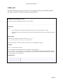
BCTSetLCDBrightness
Sets the LCD brightness to the value specified
DWORD WINAPI BCTSetLCDBrightness(BYTE bBrightness);
Parameters
bBrightness
[in] The brightness value to write
Return Value
If the function succeeds, the return value is RE1_LCD_OK.
If the function fails, the return value is a nonzero error code defined in BCTLCDBrightnessAPI.h.
Remarks
When bBrightness is set to 0 the LCD will be at its dimmest.
Requirements
Header
Declared in BCTLCDBrightnessAPI.h
Library
BCTLCDBrightnessAPI.lib
DLL
BCTLCDBrightnessAPI.dll
Page 24
Hardware API libraries
BCTGetLCDBrightness
Retrieves the current LCD brightness.
DWORD WINAPI BCTGetLCDBrightness(PBYTE bBrightness);
Parameters
bBrightness
[out] A pointer to a byte that will hold the current LCD brightness
Return Value
If the function succeeds, the return value is RE1_LCD_OK.
If the function fails, the return value is a nonzero error code defined in BCTLCDBrightnessAPI.h.
Remarks
When bBrightness is set to 0 the LCD will be at its dimmest.
Requirements
Header
Declared in BCTLCDBrightnessAPI.h
Library
BCTLCDBrightnessAPI.lib
DLL
BCTLCDBrightnessAPI.dll
Page 25
Hardware API libraries
GPIO API
The GPIO API library provides access to the 12 available GPIO pins on the RE1 platform.
The library exports five functions which are detailed below.
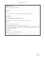
BCTSetGPIOPinDirection
Sets the directions of GPIO bits to either input or output.
DWORD WINAPI BCTSetGPIOPinDirection(WORD wVal);
Parameters
wVal
[in] A bitmap of the required pin directions. Bit set = input. Bit cleared = output.
E.g. Passing a value of 0x05 into the function would set bits 0 and 2 to inputs and other bits to
outputs
Return Value
If the function succeeds, the return value is GPIO_OK or
GPIO_OK_SOME_BITS_BELONG_TO_PERIPHERAL.
If the function fails, the return value is a nonzero error code defined in gpio.h.
Remarks
Bits 12 – 15 of wVal are ignored.
If some GPIO bits are shared with either the IRDA or I2S peripherals
GPIO_OK_SOME_BITS_BELONG_TO_PERIPHERAL is returned. This should be considered a warning
and not an error. If the GPIO pins are sharing with either the IRDA or I2S peripherals the bits relating
to the peripheral(s) will be ignored.
Requirements
Header
Declared in GPIO.h
Library
Use GPIOapi.lib
DLL
Requires GPIOapi.dll
Page 26
Hardware API libraries
BCTReadGPIOPort
Reads the current state of the GPIO port
DWORD WINAPI BCTReadGPIOPort (PWORD pwVal);
Parameters
pwVal
[out] A pointer to an 16 bit value that will hold the value of the GPIO port.
Return Value
If the function succeeds, the return value is GPIO_OK or
GPIO_OK_SOME_BITS_BELONG_TO_PERIPHERAL.
If the function fails, the return value is a nonzero error code defined in gpio.h.
Remarks
Bits 12 – 15 of pwVal should be ignored.
If some GPIO bits are shared with either the IRDA or I2S peripherals
GPIO_OK_SOME_BITS_BELONG_TO_PERIPHERAL is returned. This should be considered a warning
and not an error. If the GPIO pins are sharing with either the IRDA or I2S peripherals the bits relating
to the peripheral will be undefined.
Requirements
Header
Declared in GPIO.h
Library
Use GPIOapi.lib.
DLL
Requires GPIOapi.dll.
Page 27
Hardware API libraries
BCTWriteGPIOPort
Writes to the GPIO port
DWORD WINAPI BCTWriteGPIOPort (WORD wVal);
Parameters
wVal
[in] The word that gets written to the GPIO port.
Return Value
If the function succeeds, the return value is GPIO_OK.
If the function fails, the return value is a nonzero error code defined in gpio.h.
Remarks
Bits 12 – 15 of wVal are ignored.
If some GPIO bits are shared with either the IRDA or I2S peripherals
GPIO_OK_SOME_BITS_BELONG_TO_PERIPHERAL is returned. This should be considered a warning
and not an error. If the GPIO pins are sharing with either the IRDA or I2S peripherals the bits relating
to the peripheral will be ignored.
GPIO 11 belongs to a separate physical peripheral at the silicon level compared to the rest of the GPIO
pins. This incurs a latency between bit 11 being set in relation to the rest of the port.
Requirements
Header
Declared in GPIO.h
Library
Use GPIOapi.lib.
DLL
Requires GPIOapi.dll.
Page 28
Hardware API libraries
BCTSetGPIOBit
Sets an individual bit to a value specified
DWORD WINAPI BCTSetGPIOBit (WORD wBitNumber, BOOL iVal);
Parameters
wBitNumber
[in] The bit that should be written. Acceptable values 0-11
iVal
[in] The value to be written to the bit. TRUE = Set, FALSE = Clear
Return Value
If the function succeeds, the return value is GPIO_OK.
If the function fails, the return value is a nonzero error code defined in gpio.h.
Remarks
Requirements
Header
Declared in GPIO.h
Library
Use GPIOapi.lib.
DLL
Requires GPIOapi.dll.
Page 29
Hardware API libraries
BCTGetGPIOBit
Gets the value of an individual bit
DWORD WINAPI BCTGetGPIOBit (WORD wBitNumber, PBOOL piVal);
Parameters
wBitNumber
[in] The bit that should be read. Acceptable values 0-11
iVal
[in] A pointer to a BOOL that will hold the state of the pin. TRUE = Set, FALSE = Clear
Return Value
If the function succeeds, the return value is GPIO_OK.
If the function fails, the return value is a nonzero error code defined in gpio.h.
Remarks
Requirements
Header
Declared in GPIO.h
Library
Use GPIOapi.lib.
DLL
Requires GPIOapi.dll.
Page 30
Hardware API libraries
Watchdog API
The Watchdog API allows the system watchdog to be used to cause a system reset in the
event of an unresponsive application. The library exports four functions which are detailed
below.
BCTEnableWatchdog
Enables the RE1 watchdog to timeout in the time specified
DWORD WINAPI BCTEnableWatchDog (BYTE bTimeout);
Parameters
bTimeout
[in] The duration in 10’s of ms before a timeout is triggered. Must be greater than 0 and less
than 128.
Return Value
If the function succeeds, the return value is WATCHDOG_OK.
If the function fails, the return value is a nonzero error code defined in watchdog.h.
Remarks
Requirements
Header
Declared in Watchdog.h
Library
Use watchdog.lib
DLL
Requires watchdog.dll
Page 31
Hardware API libraries
BCTDisableWatchdog
Disables the RE1 watchdog.
DWORD WINAPI BCTDisableWatchDog (VOID);
Parameters
Return Value
If the function succeeds, the return value is WATCHDOG_OK.
If the function fails, the return value is a nonzero error code defined in watchdog.h.
Remarks
Requirements
Header
Declared in Watchdog.h
Library
Use watchdog.lib.
DLL
Requires watchdog.dll.
BCTRefreshWatchdog
Resets the watchdog counter to the timeout value.
DWORD WINAPI BCTRefreshWatchDog (VOID);
Parameters
Return Value
If the function succeeds, the return value is WATCHDOG_OK.
If the function fails, the return value is a nonzero error code defined in watchdog.h.
Remarks
Requirements
Header
Declared in Watchdog.h & azfavr.h
Library
Use watchdog.lib.
DLL
Requires watchdog.dll.
Page 32
Hardware API libraries
System Reset
The RE1 Windows CE 6 platform allows the system to be reset using system events.
The two available system events are:
Event Name
RE1_EVENT_COLD_BOOT_RESET
RE1_EVENT_WARM_BOOT_RESET
Event Description
When set causes a system warm boot
When set causes a system cold boot
Please see the ResetSystemSample application included in the Windows CE 6.0 SDK for
details on how to use these events.
Page 33
Hardware API libraries
Appendix A – Windows CE components included in the
generic Windows CE image for RE1
SYSGEN_ACM_MSFILTER, SYSGEN_ASYNCMAC, SYSGEN_AS_BASE, SYSGEN_ATL,
SYSGEN_AUDIO, SYSGEN_AUDIO_ACM, SYSGEN_AUDIO_STDWAVEFILES, SYSGEN_AUTH,
SYSGEN_AUTH_SCHANNEL, SYSGEN_AUTORAS, SYSGEN_AYGSHELL, SYSGEN_CEDDK,
SYSGEN_CEPLAYER, SYSGEN_CERTS, SYSGEN_CMD, SYSGEN_COMMCTRL, SYSGEN_COMMDLG,
SYSGEN_CONNMC, SYSGEN_CONSOLE, SYSGEN_CORELOC, SYSGEN_CORESTRA,
SYSGEN_CPP_EH_AND_RTTI, SYSGEN_CREDMAN, SYSGEN_CRYPTO, SYSGEN_CTLPNL,
SYSGEN_CURSOR, SYSGEN_DCOM, SYSGEN_DEVICE, SYSGEN_DEVLOAD, SYSGEN_DHCPSRV,
SYSGEN_DISPLAY, SYSGEN_DOTNETV2, SYSGEN_DOTNETV2_SUPPORT, SYSGEN_DSHOW,
SYSGEN_DSHOW_ACMWRAP, SYSGEN_DSHOW_DISPLAY, SYSGEN_DSHOW_DMO,
SYSGEN_DSHOW_IMAADPCM, SYSGEN_DSHOW_MP3, SYSGEN_DSHOW_MPEGA,
SYSGEN_DSHOW_MPEGSPLITTER, SYSGEN_DSHOW_MSADPCM, SYSGEN_DSHOW_MSG711,
SYSGEN_DSHOW_MSGSM610, SYSGEN_DSHOW_WAV, SYSGEN_DSHOW_WAVEOUT,
SYSGEN_DSHOW_WMA, SYSGEN_DSHOW_WMA_VOICE, SYSGEN_DSHOW_WMP,
SYSGEN_DSHOW_WMT, SYSGEN_DSHOW_WMT_ASXV1, SYSGEN_DSHOW_WMT_ASXV2,
SYSGEN_DSHOW_WMT_ASXV3, SYSGEN_DSHOW_WMT_HTTP, SYSGEN_DSHOW_WMT_LOCAL,
SYSGEN_DSHOW_WMT_MMS, SYSGEN_DSHOW_WMT_MULTI, SYSGEN_DSHOW_WMT_NSC,
SYSGEN_ETHERNET, SYSGEN_EXFAT, SYSGEN_FATFS, SYSGEN_FIBER, SYSGEN_FMTMSG,
SYSGEN_FMTRES, SYSGEN_FONTS_ARIAL_1_30, SYSGEN_FONTS_COUR_1_30,
SYSGEN_FONTS_SYMBOL, SYSGEN_FONTS_TAHOMA_1_07, SYSGEN_FONTS_TIMES_1_30,
SYSGEN_FONTS_WEBDINGS, SYSGEN_FONTS_WINGDING, SYSGEN_FSDBASE,
SYSGEN_FSPASSWORD, SYSGEN_FSRAMROM, SYSGEN_FSREGHIVE, SYSGEN_FSREPLBIT,
SYSGEN_FULL_CRT, SYSGEN_GDI_ALPHABLEND, SYSGEN_GRADFILL, SYSGEN_HTTPD,
SYSGEN_IESAMPLE, SYSGEN_IE_JSCRIPT, SYSGEN_IE_VBSCRIPT, SYSGEN_IMAGING,
SYSGEN_IMAGING_BMP_DECODE, SYSGEN_IMAGING_BMP_ENCODE,
SYSGEN_IMAGING_GIF_DECODE, SYSGEN_IMAGING_GIF_ENCODE,
SYSGEN_IMAGING_JPG_DECODE, SYSGEN_IMAGING_JPG_ENCODE,
SYSGEN_IMAGING_PNG_DECODE, SYSGEN_IMAGING_PNG_ENCODE, SYSGEN_IMM,
SYSGEN_INETCPL, SYSGEN_IPHLPAPI, SYSGEN_IRDA, SYSGEN_JSCRIPT_AUTHOR,
SYSGEN_JSCRIPT_ENCODE, SYSGEN_LOCALAUDIO, SYSGEN_MENU_OVERLAP,
SYSGEN_MINGDI, SYSGEN_MINGWES, SYSGEN_MININPUT, SYSGEN_MINWMGR,
SYSGEN_MLANG, SYSGEN_MODEM, SYSGEN_MSGQUEUE, SYSGEN_MSHTML, SYSGEN_MSMQ,
SYSGEN_MSPART, SYSGEN_MSXML_DOM, SYSGEN_MSXML_XQL, SYSGEN_NDIS,
SYSGEN_NDISUIO, SYSGEN_NETUTILS, SYSGEN_NKCOMPR, SYSGEN_NKMAPFILE,
SYSGEN_NOTIFY, SYSGEN_PM, SYSGEN_PPP, SYSGEN_PRINTING, SYSGEN_PWORD,
SYSGEN_QVGAP, SYSGEN_REDIR, SYSGEN_RELFSD, SYSGEN_SDBUS, SYSGEN_SD_MEMORY,
SYSGEN_SERDEV, SYSGEN_SERVICES, SYSGEN_SHDOCVW, SYSGEN_SHELL,
SYSGEN_STANDARDSHELL, SYSGEN_STDIO, SYSGEN_STDIOA, SYSGEN_STOREMGR,
SYSGEN_STREAMAUDIO, SYSGEN_STRSAFE, SYSGEN_TAPI, SYSGEN_TCPIP,
SYSGEN_TCPIP6, SYSGEN_TIMESVC_DST, SYSGEN_TOOLHELP, SYSGEN_TOUCH,
SYSGEN_UIPROXY, SYSGEN_UNIMODEM, SYSGEN_URLMON, SYSGEN_USB, SYSGEN_USBFN,
SYSGEN_USBFN_SERIAL, SYSGEN_USBFN_STORAGE, SYSGEN_USB_HID,
SYSGEN_USB_HID_CLIENTS, SYSGEN_USB_HID_KEYBOARD, SYSGEN_USB_HID_MOUSE,
SYSGEN_USB_PRINTER, SYSGEN_USB_STORAGE, SYSGEN_VBSCRIPT_AUTHOR,
SYSGEN_VBSCRIPT_ENCODE, SYSGEN_VBSCRIPT_MSGBOX, SYSGEN_VEM, SYSGEN_WCELOAD,
SYSGEN_WININET, SYSGEN_WINSOCK
Page 34