1
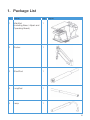
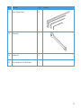
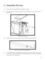
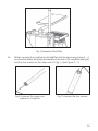
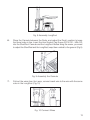
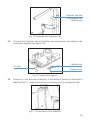
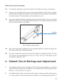
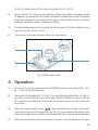
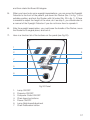
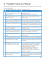
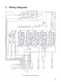
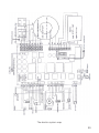
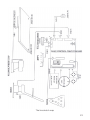
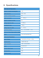
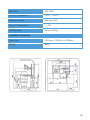
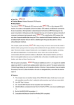
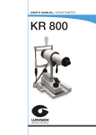
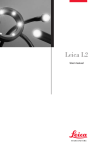
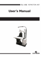
Notification
Dear Users,
Thank you for your purchase of RU 1400 Refraction Unit. Please take time to read our
user’s manual carefully before use.
This guarantees you to make full use of this unit and prolongs the operation life of
this unit.
Precautions
If you have detected abnormal heat, smoke, noise or smell, immediately stop using
the product.
In the event of an abnormality, turn off the power and disconnect the power plug from
the power socket. Continuing to use the product may result in electric shock or fire.
Observe the instructions given below regarding the power cable:
•
•
•
•
•
•
Be sure to use the supplied or specified power cable.
Do not modify, forcibly bend, kink or pull the power cable.
When disconnecting the power cable from the AC outlet, be sure to hold the cable
by the plug.
Pulling the cable may cause wire breakage or shot circuit, resulting in fire or electric
shock.
Do not connect or disconnect the plug of the power cable to/from the AC outlet
using wet hands.
Doing so may result in electric shock.
Do not touch the product with wet hands while the power cable is connected
to the AC outlet.
Doing so may result in electric shock.
If the product will not be used for a long period, disconnect the power cable
from the power source. Leaving the cable connected to the power socket for
a prolonged period will consume electricity and may result in heating.
Content
1.
Package List .................................................................................................4
2.
Name of Parts ...............................................................................................7
3.
Assembly Process .........................................................................................9
4.
Default Circuit Settings and Adjustment .......................................................15
5.
Operation ....................................................................................................16
6.
Possible failure and Repair ...........................................................................18
7.
Wiring Diagram ............................................................................................19
8.
Specifications ..............................................................................................22
1. Package List
ID
Name
Qty. Figure
1
MainPart
(including Base, Liftpart and
Operating Board).
1
2
Rocker
1
3
ShortRod
1
4
LongRod
1
5
Lamp
1
4
ID
Name
Qty. Figure
6
Back
1
7
Cannula
1
8
Hex Socket Cap Screw
ISO 4762-M8X120
1
9
Projector Flat and
Countersunk Flat Head Screw
1
10
Power Cable
11
Communication Cable
12
Fuse 5A
5
ID
Name
Qty. Figure
13
Hex Spanners
4
14
Wrench
1
15
Manual
1
16
Acceptance Certificate
1
6
2. Name of Parts
Refer to figure 16 and Figure 1 to understand the instrument’s components.
23
22
1
21
2
3
20
4
19
18
5
6
7
17
8
16
9
10
15
11
14
12
13
Fig.1 Components diagram (1)
7
26
27
28
24
25
Fig.2 Components diagram (2)
1. Projector Flat
2. Rocker Installing Rod
3. Rocker
4. Back
5. Armrest
6. Operating Board
7. DC Output Voltage Adjustment
8. Chiar down/up botton
9. Cushion
10. Chair Frame
11. Chair Cover
12. Baffle
13. Footboard
14. Base
15. Mainframe
16. Panel
17. Handle
18. ShortRod
19. Cannula
20. Rocker locker
21. LongRod
22. Connector Pipe
23. Lamp
24. Screws
25. Power Switch
26. HorizontalRod on Rocker
27. Headrest
28. Lifting Switch
8
3. Assembly Process
1.
First at all, you should place the MainPart on a flat.
2.
Unscrew the two screws on the back of the MainPart, so you can open it’s
back (fig.3)
Fig.3 Unfix the back
3.
Unscrew the screw and washer on the end of the ShortRod (fig.4)
Fig.4 Unscrew screw and washer
4.
Fit the ShortRod on the MainPart according to the place showed in figure 5.
In this step, do not make the screw completely fixed, so that you can adjust
the position of the ShortRod.
9
Fig. 5 Assembly ShortRod
5.
Before mounting the LongRod on the MainPart with the same way as step 3 ~ 4,
you should unscrew the screw and washer at the end of the LongRod (see fig.6),
and the four screws on the other end of it (fig.7). See Figure 6 ~ 8.
Fig 6 Unscrew the screw and
washer on LongRod
Fig.7 Unscrew the four screws
10
Fig. 8 Assembly LongRod
6.
Place the Cannula between the Rods, and adjust the Rods’ position to keep
the three holes in line. Insert the Hex Socket Cap Screw ISO 4762 - M8x120
into the ShortRod. Cannula and the LongRod. Before fixing the screw, you need
to adjust the ShortRod and the LongRod, keep them vertical to the ground. (Fig 9)
Fig. 9 Assembly the Cannula
7.
Pull out the wires from the Lamp, connect each wire to the wire with the same
color in the LongRod. (Fig.10)
Fig. 10 Connect Wires
11
8.
In order to keep the lamp horizontal, one person should buttress the lamp in
this step. Adjust the lamp to the right position, and fix the four screws unscrewed
from the LongRod to the corresponding position and make them tightened, (fig.7).
See the figure 11.
Fig.11 Assembly the Lamp
9.
After the ShortRod, LongRod and the Lamp has been set up, you should adjust
their position to keep the ShortRod and LongRod vertical to the ground. At last,
tighten each screws (fig.5, 8 ,9).
10.
Unscrew the three bolts and nuts on the chair of the MainPart. see figure 12.
Three bolts and nuts
Fig.12 Unscrew three bolts and nuts
11.
Align the three holes on the Back and their corresponding holes on the chair,
fix the Back to MainPart reliably with the three bolds and nuts. See figure 13.
12
Fig.13 Fix the Back
12.
Hang the Rocker onto the ShortRod, make sure that the Rocker can run softly
and comfortably. See figure 14.
Fig.14 Assembly the Rocker
13.
To install the Projector Flat with the Countersunk Flat Head Screw. Keep the
length of the power plug wire 260mm,see figure 15. On the back of Flat, there
was fixed a universal, you need to test it’s swing motion.
13
Projector Flat and
Countersunk Flat
Head Screw
Fig. 15 Assembly the Projector Flat
14.
Connect the Projector wire and lighting wire respectively according to the
connection diagram (see figure 16).
Lighting wire
AC Input
Projector wire
Fig.13 Connection diagram
15.
Power on to test the wire connection. If connection is correct, fix the back of
MainPart (fig.17); make sure that the two screws are not screwed so tight.
Fig.17 Fix the back of the MainPart
14
Other Accessories Assembly
16.
To install the Projector onto the Projector Flat with the screws, and plug in.
17.
Hang up the Eyesight Detector onto the HorizontalRod of the Rocker, tighten
its locking knob. Adjust the position of the detector via the handle on the Rocker,
and then adjust it’s horizontality via the bubble cell on it.
18.
Loose the handle of Rocker, Eyesight Detector will rise slowly. If not, you should
adjust the strain of the controlling spring,see fig.18, the strain enhances during
a clock-wise rotation, vice versa.
Wrench
Fig.18 Adjust spring strain
19.
Set up the optometry facilities on the operating Board, connect its plugs into
the outlet under the operating Board.
20.
You can connect the wires for the two DC outputs on operating board. The two
DC outputs can be adjusted to 3V, 6V, 9V, 12V or 24V. You can adjust on the
mainboard, default is 12V.
4. Default Circuit Settings and Adjustment
1.
The default setting of local voltage is 220V. When firstly installed, you should
check that the transformer should be in accordance the local supply power
(220V or 110V), see No.1 in Fig.19.
2.
The default status of the computer power supply is always standby when power
on. If you want to control the power by the button on controlling panel (see No. 3
15
in Fig 20), please take off the circuit ring (see No.2 in Fig 19)
3.
About the two DC output on the platform. When the platform rotates outside
20 degrees, the power shut off. When the platform rotates back inside 20 degrees
the power continues. If you pull out the plug on the rnainboard, the DV output
is always standby in spite of platform rotating.
4.
The flow bridge close to the circuit is left direct current. The flow bridge far form
the circuit is right direct current.
5.
The entry of the normal power made the chair works.
3
1
2
Fig.19 Mainboard Chart
5. Operation
1.
Power on the facility, and press the [POWER] button on the Panel (No. 16 in
fig. 1), the facility will stand by.
2.
Press down the handle (No. 17 in fig. 1) on the Operating Board (No. 6 in fig. 1),
you can move the Board to the left or right. When the Board moves to left, the
DC output on left (default is 12V) power on, and the output on right is shut off,
vice versa.
3.
Press the height-adjust buttons ([ ][ ], the two buttons are located on the panel
or on the front plane of the Board (No. 8 in fig. 1)), you can adjust the height of the
chair. You can also use the switch on the back of the chair to do the same operation.
4.
When the examination has been finished, you can move the Board to its origin,
16
and then rotate the Board 90-degree.
5.
When you have to do some eyesight examinations, you can move the Eyesight
Detector to the front of the patient, pull down the Rocker (No. 3 in fig. 1) to a
suitable position, and lock the Rocker with it’s locker (No. 20 in fig. 1). If there
is needed to adjust the height of the chair, do it as step 3; you should refer to
a manual of the Eyesight Detector if you do not know how to operate it.
6.
After the eyesight examination, you must loose the handle of the Rocker, move
the Rocker to its onginal place, and lock it.
7.
Here is a function list of the buttons on the panel (see Fig 20).
1
2
3
4
7
5
6
Fig 20 Panel
1.
2.
3.
4.
5.
6.
7.
Lamp ON/OFF
Projector ON/OFF
Computer Outlet ON/OFF
Chair down/up buttons
Power ON/OFF
Lamp BrightnessAdjustment
Chair Restoration button
17
6. Possible Failure and Repair
Here are some frequent failures or something happened possibly when you operate
this combined table.
You can examine the facility or repair it according to the list.
Failures
Possible reasons and repair suggestion
1
The indicator light has no light
when power on
Checking the fuse.
Checking the status of the socket.
2
The indicator light has light but it
doesn’t work yet.
Checking if the plug of the control panel
connect right.
3
It doesn’t work when started while the Checking if the control panel keeps perfect,
power and the control panel is on. or if the voltage is be up to the standard.
4
The power of the projector isn’t on. Checking if the line of the projector is well
connected, or if the whole line has short circuit.
5
The two DC supply power on the
board isn’t prepared.
Checking if the line is well connected, or if
the plug is loose.
6
The switch of the controlling chair
under the board shows no power.
Checking if the switch keeps perfect, or if
the line is connected in the right way.
7
The chair can rise but can’t go
down.
Checking if the journey switch under the
table is normal.
8
The chair goes down automatically.
Adjusting the screw on the electromagnetism.
9
The head lamp has no light.
Checking if the lamp is damaged, or if the line
is kept well.
10 When going up or down, there
is a big noise with the engine.
11 It doesn’t work after checking the
above questions.
a) It shows that some place is leaked and
the unilateral plug needs to be changed.
Please contact with the factory or the
maintenance place to change.
b) It has low temperature in winter, the
density of the oil is high, so it might
happened, it will be OK in ten minutes or
so after it is started.
Contact with the factory or the maintenance
place, let the professional check the instrument
or replace the part.
18
7. Wiring Diagram
The electric principle map
19
The electric system map
20
The line sketch map
21
8. Specifications
Mechanical Parameters
Angle of rotation for swing arm
±30
Table size(mm)
840 x 405
Angle of rotation for table
90°
Table rnovement
0 ~ 330mm
Angle of rotation for chair
60
Lifting height for chair
0-180mm
Loading for chair
150Kg
Lifting height for pillow
0 ~ 70 mm
Backrest obliquity
90° ~ 135° to 900° ~ 140°
Table and Case using complex material
Color
ivory and sapphire blue
Electrical Parameters
Input Voltage
110V/220V AC 50Hz ~ 60Hz
Engine power
140W 220V AC
Light Luminaire
15W 110V/220VAV
Fuse
5A 250V AC
Power without load
1W
PressureTest
2KV
Working mode
S1
22
Main Wire
10A 250V
Working Temperature
-30°C ~ +50°C
Relative Humidity
less than 90%
Force of Pressing key
1 ~ 5N
Cooling mode
Nature cooling
Installation Dimension
Figure size:
1400mm x 1000mm x 1990mm
Weight:
98Kg
23
LUXVISION is not responsible or liable for indirect, special or consequential damages arising out of or in
connection with the use or performance of the product or damages with respect to any economic loss,
loss of property, loss of revenues or profits, loss of enjoyment or use, costs of removal or installation or
other consequential damages of whatsoever nature. Some states do not allow the exclusion or limitation
of incidental or consequential damages. Accordingly, the above limitation may not apply to you.
Every effort has been made to ensure the accuracy of this manual. However, LUXVISION, makes no
warranties with respect to the documentation and disclaims any implied warranties of merchantability
and fitness for a particular purpose. LUXVISION, Inc. shall not be liable for any errors or for incidental or
consequential damages in connection with the furnishing, performance, or use of this manual or the examples
herein. The information in this document is subject to change without notice.
24