1
User and Measurement Guide with SCPI Programming
PIM Master™
Passive Intermodulation Analyzer
MW82119A
Anritsu Company
490 Jarvis Drive
Morgan Hill, CA 95037-2809
USA
http://www.anritsu.com
Part Number: 10580-00285
Revision: H
Published: August 2014
Copyright 2012, 2014 Anritsu Company
WARRANTY
The Anritsu product listed on the title page is warranted against defects in materials and workmanship
for three years from the date of shipment.
Anritsu’s obligation covers repairing or replacing products which prove to be defective during the
warranty period. Buyers shall prepay transportation charges for equipment returned to Anritsu for
warranty repairs. Obligation is limited to the original purchaser. Anritsu is not liable for consequential
damages. Accessories included with this product are not included in the standard warranty.
LIMITATION OF WARRANTY
The foregoing warranty does not apply to Anritsu connectors that have failed due to normal wear. Also,
the warranty does not apply to defects resulting from improper or inadequate maintenance by the
Buyer, unauthorized modification or misuse, or operation outside of the environmental specifications of
the product. No other warranty is expressed or implied, and the remedies provided herein are the
Buyer’s sole and exclusive remedies.
DISCLAIMER OF WARRANTY
DISCLAIMER OF WARRANTIES. TO THE MAXIMUM EXTENT PERMITTED BY APPLICABLE
LAW, ANRITSU COMPANY AND ITS SUPPLIERS DISCLAIM ALL WARRANTIES, EITHER
EXPRESSED OR IMPLIED, INCLUDING, BUT NOT LIMITED TO, IMPLIED WARRANTIES OF
MERCHANTABILITY AND FITNESS FOR A PARTICULAR PURPOSE, WITH REGARD TO THE
PRODUCT. THE USER ASSUMES THE ENTIRE RISK OF USING THE PRODUCT. ANY LIABILITY
OF PROVIDER OR MANUFACTURER WILL BE LIMITED EXCLUSIVELY TO PRODUCT
REPLACEMENT.
NO LIABILITY FOR CONSEQUENTIAL DAMAGES. TO THE MAXIMUM EXTENT PERMITTED BY
APPLICABLE LAW, IN NO EVENT SHALL ANRITSU COMPANY OR ITS SUPPLIERS BE LIABLE
FOR ANY SPECIAL, INCIDENTAL, INDIRECT, OR CONSEQUENTIAL DAMAGES WHATSOEVER
(INCLUDING, WITHOUT LIMITATION, DAMAGES FOR LOSS OF BUSINESS PROFITS,
BUSINESS INTERRUPTION, LOSS OF BUSINESS INFORMATION, OR ANY OTHER PECUNIARY
LOSS) ARISING OUT OF THE USE OF OR INABILITY TO USE THE PRODUCT, EVEN IF ANRITSU
COMPANY HAS BEEN ADVISED OF THE POSSIBILITY OF SUCH DAMAGES. BECAUSE SOME
STATES AND JURISDICTIONS DO NOT ALLOW THE EXCLUSION OR LIMITATION OF
LIABILITY FOR CONSEQUENTIAL OR INCIDENTAL DAMAGES, THE ABOVE LIMITATION MAY
NOT APPLY TO YOU.
TRADEMARK ACKNOWLEDGMENTS
PIM Master and Distance-to-PIM are registered trademarks of Anritsu Company.
Acrobat Reader is a registered trademark of Adobe Corporation
Windows® is a registered trademark of Microsoft Corporation.
NOTICE
Anritsu Company has prepared this manual for use by Anritsu Company personnel and customers as a
guide for the proper installation, operation and maintenance of Anritsu Company equipment and
computer programs. The drawings, specifications, and information contained herein are the property of
Anritsu Company, and any unauthorized use or disclosure of these drawings, specifications, and
information is prohibited; they shall not be reproduced, copied, or used in whole or in part as the basis
for manufacture or sale of the equipment or software programs without the prior written consent of
Anritsu Company.
UPDATES
Updates, if any, can be downloaded from the Anritsu Website at:
http://www.anritsu.com
For the latest service and sales contact information in your area, please visit:
http://www.anritsu.com/contact.asp
CE Conformity Marking
Anritsu affixes the CE Conformity marking onto its conforming products in accordance with
Council Directives of The Council Of The European Communities in order to indicate that
these products conform to the EMC and LVD directive of the European Union (EU).
C-tick Conformity Marking
Anritsu affixes the C-tick marking onto its conforming products in accordance with the
electromagnetic compliance regulations of Australia and New Zealand in order to indicate
that these products conform to the EMC regulations of Australia and New Zealand.
Notes On Export Management
This product and its manuals may require an Export License or approval by the government
of the product country of origin for re-export from your country.
Before you export this product or any of its manuals, please contact Anritsu Company to
confirm whether or not these items are export-controlled.
When disposing of export-controlled items, the products and manuals need to be broken or
shredded to such a degree that they cannot be unlawfully used for military purposes.
MW82119A UG
PN: 10580-00285 Rev. H
TG-5
TG-6
PN: 10580-00285 Rev. H
MW82119A UG
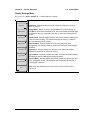
Safety Symbols
To prevent the risk of personal injury or loss related to equipment malfunction, Anritsu
Company uses the following symbols to indicate safety-related information. For your own
safety, please read the information carefully before operating the equipment.
Symbols Used in Manuals
Danger
This indicates a risk from a very dangerous condition or procedure that
could result in serious injury or death and possible loss related to equipment
malfunction. Follow all precautions and procedures to minimize this risk.
Warning
This indicates a risk from a hazardous condition or procedure that could
result in light-to-severe injury or loss related to equipment malfunction.
Follow all precautions and procedures to minimize this risk.
Caution
This indicates a risk from a hazardous procedure that could result in loss
related to equipment malfunction. Follow all precautions and procedures to
minimize this risk.
Safety Symbols Used on Equipment and in Manuals
The following safety symbols are used inside or on the equipment near operation locations to
provide information about safety items and operation precautions. Ensure that you clearly
understand the meanings of the symbols and take the necessary precautions before operating
the equipment. Some or all of the following five symbols may or may not be used on all
Anritsu equipment. In addition, there may be other labels attached to products that are not
shown in the diagrams in this manual.
This indicates a prohibited operation. The prohibited operation is indicated
symbolically in or near the barred circle.
This indicates a compulsory safety precaution. The required operation is
indicated symbolically in or near the circle.
This indicates a warning or caution. The contents are indicated symbolically
in or near the triangle.
This indicates a note. The contents are described in the box.
These indicate that the marked part should be recycled.
MW82119A UG
PN: 10580-00285 Rev. H
Safety-1
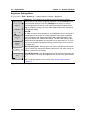
For Safety
Warning
Always refer to the operation manual when working near locations at
which the alert mark, shown on the left, is attached. If the operation,
etc., is performed without heeding the advice in the operation
manual, there is a risk of personal injury. In addition, the equipment
performance may be reduced. Moreover, this alert mark is sometimes
used with other marks and descriptions indicating other dangers.
Warning
When supplying power to this equipment, connect the accessory
3-pin power cord to a 3-pin grounded power outlet. If power is
supplied without grounding the equipment, there is a risk of receiving
a severe or fatal electric shock.
Warning
Caution
This equipment can not be repaired by the operator. Do not attempt to
remove the equipment covers or to disassemble internal
components. Only qualified service technicians with a knowledge of
electrical fire and shock hazards should service this equipment.
There are high-voltage parts in this equipment presenting a risk of
severe injury or fatal electric shock to untrained personnel. In
addition, there is a risk of damage to precision components.
Electrostatic Discharge (ESD) can damage the highly sensitive
circuits in the instrument. ESD is most likely to occur as test devices
are being connected to, or disconnected from, the instrument’s front
and rear panel ports and connectors. You can protect the instrument
and test devices by wearing a static-discharge wristband.
Alternatively, you can ground yourself to discharge any static charge
by touching the outer chassis of the grounded instrument before
touching the instrument’s front and rear panel ports and connectors.
Avoid touching the test port center conductors unless you are
properly grounded and have eliminated the possibility of static
discharge.
Repair of damage that is found to be caused by electrostatic
discharge is not covered under warranty.
Warning
Safety-2
This product is supplied with a rechargeable battery that could
potentially leak hazardous compounds into the environment. These
hazardous compounds present a risk of injury or loss due to
exposure. Anritsu Company recommends removing the battery for
long-term storage of the instrument and storing the battery in a
leak-proof, plastic container. Follow the environmental storage
requirements specified in the product technical data sheet.
PN: 10580-00285 Rev. H
MW82119A UG
Table of Contents
Chapter 1—General Information
1-1
Introduction . . . . . . . . . . . . . . . . . . . . . . . . . . . . . . . . . . . . . . . . . . . . . . . . . 1-1
Chapter Overview . . . . . . . . . . . . . . . . . . . . . . . . . . . . . . . . . . . . . . . . . 1-1
Scope of the PIM Master User Guide . . . . . . . . . . . . . . . . . . . . . . . . . . 1-2
1-2
Contacting Anritsu
1-3
Anritsu Service Centers
1-4
Additional Documentation. . . . . . . . . . . . . . . . . . . . . . . . . . . . . . . . . . . . . . 1-3
The PIM Master . . . . . . . . . . . . . . . . . . . . . . . . . . . . . . . . . . . . . . . . . . 1-4
1-5
PIM Master Options . . . . . . . . . . . . . . . . . . . . . . . . . . . . . . . . . . . . . . . . . . 1-5
1-6
PIM Master Performance Specifications . . . . . . . . . . . . . . . . . . . . . . . . . . 1-5
Calibration Requirements . . . . . . . . . . . . . . . . . . . . . . . . . . . . . . . . . . . 1-5
1-7
ESD Caution
1-8
Anritsu Line Sweep Tools (LST)
1-9
Wireless Remote Control of PIM Analyzer
. . . . . . . . . . . . . . . . . . . . . . . . . . . . . . . . . . . . . . . . 1-3
. . . . . . . . . . . . . . . . . . . . . . . . . . . . . . . . . . . . . 1-3
. . . . . . . . . . . . . . . . . . . . . . . . . . . . . . . . . . . . . . . . . . . . . . 1-6
. . . . . . . . . . . . . . . . . . . . . . . . . . . . . . 1-6
. . . . . . . . . . . . . . . . . . . . . . . 1-6
1-10 PIM Master Firmware Update. . . . . . . . . . . . . . . . . . . . . . . . . . . . . . . . . . . 1-6
1-11 PIM Master Option Update . . . . . . . . . . . . . . . . . . . . . . . . . . . . . . . . . . . . . 1-7
1-12 Standard and Optional Accessories . . . . . . . . . . . . . . . . . . . . . . . . . . . . . 1-7
1-13 What is PIM? . . . . . . . . . . . . . . . . . . . . . . . . . . . . . . . . . . . . . . . . . . . . . . 1-7
Power in dBm and dBc
. . . . . . . . . . . . . . . . . . . . . . . . . . . . . . . . . . . 1-7
1-14 Why Test for PIM? . . . . . . . . . . . . . . . . . . . . . . . . . . . . . . . . . . . . . . . . . . . 1-9
Line Sweeping and PIM testing
. . . . . . . . . . . . . . . . . . . . . . . . . . . 1-9
Causes of PIM
. . . . . . . . . . . . . . . . . . . . . . . . . . . . . . . . . . . . . . . . . 1-9
PIM Testing Example . . . . . . . . . . . . . . . . . . . . . . . . . . . . . . . . . . . . . 1-11
1-15 PIM Testing Procedure . . . . . . . . . . . . . . . . . . . . . . . . . . . . . . . . . . . . . . 1-12
Recommended Testing Procedure . . . . . . . . . . . . . . . . . . . . . . . . . . 1-13
1-16 Test Reports
. . . . . . . . . . . . . . . . . . . . . . . . . . . . . . . . . . . . . . . . . . . . . 1-14
Chapter 2—PIM Master Overview
2-1
Introduction . . . . . . . . . . . . . . . . . . . . . . . . . . . . . . . . . . . . . . . . . . . . . . . . . 2-1
2-2
Chapter Overview . . . . . . . . . . . . . . . . . . . . . . . . . . . . . . . . . . . . . . . . . . . . 2-1
2-3
Instrument Description . . . . . . . . . . . . . . . . . . . . . . . . . . . . . . . . . . . . . . . . 2-2
2-4
Connector Care . . . . . . . . . . . . . . . . . . . . . . . . . . . . . . . . . . . . . . . . . . . . . 2-3
Connecting Procedure. . . . . . . . . . . . . . . . . . . . . . . . . . . . . . . . . . . . . . 2-3
Disconnecting Procedure . . . . . . . . . . . . . . . . . . . . . . . . . . . . . . . . . . . 2-3
Connector Saver
. . . . . . . . . . . . . . . . . . . . . . . . . . . . . . . . . . . . . . . 2-4
2-5
Hardware Overview . . . . . . . . . . . . . . . . . . . . . . . . . . . . . . . . . . . . . . . . . . 2-4
MW82119A PIM Master Front Panel . . . . . . . . . . . . . . . . . . . . . . . . . . 2-5
MW82119A UG
PN: 10580-00285 Rev. H
Contents-1
Table of Contents (Continued)
2-6
Front Panel Keys
. . . . . . . . . . . . . . . . . . . . . . . . . . . . . . . . . . . . . . . . . 2-7
2-7
Top Connector Panel . . . . . . . . . . . . . . . . . . . . . . . . . . . . . . . . . . . . . . . . 2-9
2-8
Side Panel Connectors . . . . . . . . . . . . . . . . . . . . . . . . . . . . . . . . . . . . . . . 2-10
2-9
Front Panel Overview . . . . . . . . . . . . . . . . . . . . . . . . . . . . . . . . . . . . . . . . 2-13
Front Panel Display Areas . . . . . . . . . . . . . . . . . . . . . . . . . . . . . . . . . 2-13
2-10 Mode Selector Menu . . . . . . . . . . . . . . . . . . . . . . . . . . . . . . . . . . . . . . . . 2-18
2-11 Secondary Function Menus
. . . . . . . . . . . . . . . . . . . . . . . . . . . . . . . . . . 2-19
2-12 Touch Screen . . . . . . . . . . . . . . . . . . . . . . . . . . . . . . . . . . . . . . . . . . . . . 2-20
Graphical User Interface (GUI) . . . . . . . . . . . . . . . . . . . . . . . . . . . . . . 2-20
Menu Key. . . . . . . . . . . . . . . . . . . . . . . . . . . . . . . . . . . . . . . . . . . . . . . 2-21
2-13 Touch Screen Calibration . . . . . . . . . . . . . . . . . . . . . . . . . . . . . . . . . . . . 2-24
Calibrate Touch Screen Shortcut . . . . . . . . . . . . . . . . . . . . . . . . . . . . 2-24
Arrow Navigation . . . . . . . . . . . . . . . . . . . . . . . . . . . . . . . . . . . . . . . 2-24
2-14 Parameter Setting . . . . . . . . . . . . . . . . . . . . . . . . . . . . . . . . . . . . . . . . . . . 2-25
2-15 Symbols and Indicators. . . . . . . . . . . . . . . . . . . . . . . . . . . . . . . . . . . . . . . 2-26
2-16 Firmware Overview . . . . . . . . . . . . . . . . . . . . . . . . . . . . . . . . . . . . . . . . . . 2-27
Main Menu Keys . . . . . . . . . . . . . . . . . . . . . . . . . . . . . . . . . . . . . . . . . 2-27
Submenu Keys . . . . . . . . . . . . . . . . . . . . . . . . . . . . . . . . . . . . . . . . . . 2-27
Initial Measurement . . . . . . . . . . . . . . . . . . . . . . . . . . . . . . . . . . . . . . 2-28
Chapter 3—Quick Start Guide
3-1
Introduction . . . . . . . . . . . . . . . . . . . . . . . . . . . . . . . . . . . . . . . . . . . . . . . . . 3-1
3-2
Chapter Overview . . . . . . . . . . . . . . . . . . . . . . . . . . . . . . . . . . . . . . . . . . . . 3-1
3-3
Turning On the PIM Master for the First Time . . . . . . . . . . . . . . . . . . . . . . 3-2
Calibration Due Date . . . . . . . . . . . . . . . . . . . . . . . . . . . . . . . . . . . . . 3-2
Calibration Reminder . . . . . . . . . . . . . . . . . . . . . . . . . . . . . . . . . . . . . . 3-3
Preparing for Measurements . . . . . . . . . . . . . . . . . . . . . . . . . . . . . . . . . 3-3
Measurement Types . . . . . . . . . . . . . . . . . . . . . . . . . . . . . . . . . . . . . . . 3-5
Calibrating . . . . . . . . . . . . . . . . . . . . . . . . . . . . . . . . . . . . . . . . . . . . . . 3-6
Verifying Residual PIM . . . . . . . . . . . . . . . . . . . . . . . . . . . . . . . . . . . 3-10
Verifying the PIM Standard
. . . . . . . . . . . . . . . . . . . . . . . . . . . . . . 3-10
Verifying the Test Cable
. . . . . . . . . . . . . . . . . . . . . . . . . . . . . . . . 3-12
Checking for External Interference . . . . . . . . . . . . . . . . . . . . . . . . . . 3-12
Making PIM Measurements . . . . . . . . . . . . . . . . . . . . . . . . . . . . . . . . 3-13
3-4
Setting Up Limit Lines . . . . . . . . . . . . . . . . . . . . . . . . . . . . . . . . . . . . . . . . 3-13
Changing Limit Line Settings . . . . . . . . . . . . . . . . . . . . . . . . . . . . . . . 3-13
3-5
Limit Alarm and Pass Indicator
3-6
Setting Up Markers . . . . . . . . . . . . . . . . . . . . . . . . . . . . . . . . . . . . . . . . . 3-16
3-7
Selecting a Mode and a Measurement Type . . . . . . . . . . . . . . . . . . . . . . 3-17
Contents-2
. . . . . . . . . . . . . . . . . . . . . . . . . . . . . . 3-14
PN: 10580-00285 Rev. H
MW82119A UG
Table of Contents (Continued)
3-8
Saving Measurements . . . . . . . . . . . . . . . . . . . . . . . . . . . . . . . . . . . . . . . 3-17
3-9
Menu Map . . . . . . . . . . . . . . . . . . . . . . . . . . . . . . . . . . . . . . . . . . . . . . . . 3-17
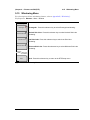
3-10 Measurements Menu . . . . . . . . . . . . . . . . . . . . . . . . . . . . . . . . . . . . . . . 3-19
Test Submenu Key During Measurement . . . . . . . . . . . . . . . . . . . . . . 3-20
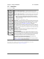
3-11 Noise Floor Menu . . . . . . . . . . . . . . . . . . . . . . . . . . . . . . . . . . . . . . . . . . 3-21
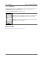
3-12 Limit Menu
. . . . . . . . . . . . . . . . . . . . . . . . . . . . . . . . . . . . . . . . . . . . . . . 3-22
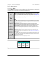
3-13 Reference (Limit) Menu
. . . . . . . . . . . . . . . . . . . . . . . . . . . . . . . . . . . . 3-23
3-14 Calibrate Menu . . . . . . . . . . . . . . . . . . . . . . . . . . . . . . . . . . . . . . . . . . . . 3-24
3-15 Custom Calibrations Menu . . . . . . . . . . . . . . . . . . . . . . . . . . . . . . . . . . . 3-25
3-16 Other Menus . . . . . . . . . . . . . . . . . . . . . . . . . . . . . . . . . . . . . . . . . . . . . . . 3-26
Marker Menu . . . . . . . . . . . . . . . . . . . . . . . . . . . . . . . . . . . . . . . . . . . . 3-26
Trace Menu . . . . . . . . . . . . . . . . . . . . . . . . . . . . . . . . . . . . . . . . . . . . . 3-26
GPS Menu . . . . . . . . . . . . . . . . . . . . . . . . . . . . . . . . . . . . . . . . . . . . . . 3-26
System Menu. . . . . . . . . . . . . . . . . . . . . . . . . . . . . . . . . . . . . . . . . . . . 3-26
File Menu. . . . . . . . . . . . . . . . . . . . . . . . . . . . . . . . . . . . . . . . . . . . . . . 3-26
Sweep Menu . . . . . . . . . . . . . . . . . . . . . . . . . . . . . . . . . . . . . . . . . . . . 3-26
Preset Menu . . . . . . . . . . . . . . . . . . . . . . . . . . . . . . . . . . . . . . . . . . . . 3-26
Chapter 4—File Management
4-1
Introduction . . . . . . . . . . . . . . . . . . . . . . . . . . . . . . . . . . . . . . . . . . . . . . . . . 4-1
4-2
Chapter Overview . . . . . . . . . . . . . . . . . . . . . . . . . . . . . . . . . . . . . . . . . . . . 4-1
4-3
Managing Files . . . . . . . . . . . . . . . . . . . . . . . . . . . . . . . . . . . . . . . . . . . . . 4-2
File Types . . . . . . . . . . . . . . . . . . . . . . . . . . . . . . . . . . . . . . . . . . . . . . 4-2
4-4
File Management . . . . . . . . . . . . . . . . . . . . . . . . . . . . . . . . . . . . . . . . . . . . 4-3
Saving Files . . . . . . . . . . . . . . . . . . . . . . . . . . . . . . . . . . . . . . . . . . . . . . 4-3
Save Dialog Box . . . . . . . . . . . . . . . . . . . . . . . . . . . . . . . . . . . . . . . . . 4-4
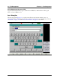
Quick Name Keys . . . . . . . . . . . . . . . . . . . . . . . . . . . . . . . . . . . . . . . . . 4-5
Recalling Files . . . . . . . . . . . . . . . . . . . . . . . . . . . . . . . . . . . . . . . . . . . 4-6
Recall Dialog Box . . . . . . . . . . . . . . . . . . . . . . . . . . . . . . . . . . . . . . . . 4-7
Copying Files . . . . . . . . . . . . . . . . . . . . . . . . . . . . . . . . . . . . . . . . . . . . 4-8
Deleting Files . . . . . . . . . . . . . . . . . . . . . . . . . . . . . . . . . . . . . . . . . . . 4-10
Delete Dialog Box . . . . . . . . . . . . . . . . . . . . . . . . . . . . . . . . . . . . . . . 4-10
4-5
File Menu Overview . . . . . . . . . . . . . . . . . . . . . . . . . . . . . . . . . . . . . . . . 4-11
4-6
File Menu . . . . . . . . . . . . . . . . . . . . . . . . . . . . . . . . . . . . . . . . . . . . . . . . 4-12
4-7
Save Menu . . . . . . . . . . . . . . . . . . . . . . . . . . . . . . . . . . . . . . . . . . . . . . . 4-13
4-8
Save Location Menu . . . . . . . . . . . . . . . . . . . . . . . . . . . . . . . . . . . . . . . . 4-14
Select Save Location Dialog Box . . . . . . . . . . . . . . . . . . . . . . . . . . . 4-15
Create Directory Dialog Box . . . . . . . . . . . . . . . . . . . . . . . . . . . . . . . 4-16
MW82119A UG
PN: 10580-00285 Rev. H
Contents-3
Table of Contents (Continued)
4-9
Recall Menu . . . . . . . . . . . . . . . . . . . . . . . . . . . . . . . . . . . . . . . . . . . . . . 4-17
Recall Dialog Box . . . . . . . . . . . . . . . . . . . . . . . . . . . . . . . . . . . . . . . 4-18
4-10 Copy Menu . . . . . . . . . . . . . . . . . . . . . . . . . . . . . . . . . . . . . . . . . . . . . . . . 4-19
Copy Dialog Box . . . . . . . . . . . . . . . . . . . . . . . . . . . . . . . . . . . . . . . . 4-20
4-11 Delete Menu . . . . . . . . . . . . . . . . . . . . . . . . . . . . . . . . . . . . . . . . . . . . . . 4-21
Chapter 5—System Operation
5-1
Introduction . . . . . . . . . . . . . . . . . . . . . . . . . . . . . . . . . . . . . . . . . . . . . . . . . 5-1
5-2
Chapter Overview . . . . . . . . . . . . . . . . . . . . . . . . . . . . . . . . . . . . . . . . . . . . 5-1
5-3
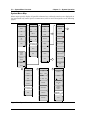
System Menu Overview . . . . . . . . . . . . . . . . . . . . . . . . . . . . . . . . . . . . . . 5-1
System Menu Map. . . . . . . . . . . . . . . . . . . . . . . . . . . . . . . . . . . . . . . . . 5-2
5-4
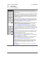
System Menu
. . . . . . . . . . . . . . . . . . . . . . . . . . . . . . . . . . . . . . . . . . . 5-3
System Options Menu . . . . . . . . . . . . . . . . . . . . . . . . . . . . . . . . . . . . . 5-4
Display Settings Menu . . . . . . . . . . . . . . . . . . . . . . . . . . . . . . . . . . . . . 5-5
Brightness Settings Menu . . . . . . . . . . . . . . . . . . . . . . . . . . . . . . . . . . 5-6
Reset Menu . . . . . . . . . . . . . . . . . . . . . . . . . . . . . . . . . . . . . . . . . . . . . 5-7
5-5
Preset Menu . . . . . . . . . . . . . . . . . . . . . . . . . . . . . . . . . . . . . . . . . . . . . . . 5-8
5-6
Self Test . . . . . . . . . . . . . . . . . . . . . . . . . . . . . . . . . . . . . . . . . . . . . . . . . . 5-8
Chapter 6—GPS (Option 31)
6-1
Introduction . . . . . . . . . . . . . . . . . . . . . . . . . . . . . . . . . . . . . . . . . . . . . . . . 6-1
6-2
Chapter Overview . . . . . . . . . . . . . . . . . . . . . . . . . . . . . . . . . . . . . . . . . . . . 6-1
6-3
Setting Up GPS (Option 31) . . . . . . . . . . . . . . . . . . . . . . . . . . . . . . . . . . . 6-1
Activating the GPS Feature . . . . . . . . . . . . . . . . . . . . . . . . . . . . . . . . . . 6-1
6-4
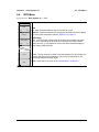
GPS Menu . . . . . . . . . . . . . . . . . . . . . . . . . . . . . . . . . . . . . . . . . . . . . . . . 6-3
GPS Info . . . . . . . . . . . . . . . . . . . . . . . . . . . . . . . . . . . . . . . . . . . . . . . . 6-4
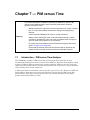
Chapter 7—PIM versus Time
7-1
Introduction – PIM versus Time Analyzer . . . . . . . . . . . . . . . . . . . . . . . . . 7-1
7-2
Chapter Overview . . . . . . . . . . . . . . . . . . . . . . . . . . . . . . . . . . . . . . . . . . . . 7-2
7-3
Noise Floor . . . . . . . . . . . . . . . . . . . . . . . . . . . . . . . . . . . . . . . . . . . . . . . . . 7-2
7-4
Trace Mode
7-5
PIM vs. Time Measurement Setup . . . . . . . . . . . . . . . . . . . . . . . . . . . . . 7-4
Configure the PIM Test . . . . . . . . . . . . . . . . . . . . . . . . . . . . . . . . . . . . . 7-4
PIM Summary Table . . . . . . . . . . . . . . . . . . . . . . . . . . . . . . . . . . . . . . 7-7
Bar Graph of Instantaneous PIM . . . . . . . . . . . . . . . . . . . . . . . . . . . . . 7-8
7-6
Making the Measurement . . . . . . . . . . . . . . . . . . . . . . . . . . . . . . . . . . . . 7-10
7-7
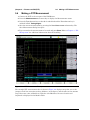
Sample of PIM versus Time Measurement . . . . . . . . . . . . . . . . . . . . . . . 7-11
Measurement with Pass Indicator . . . . . . . . . . . . . . . . . . . . . . . . . . . . 7-12
7-8
Menu Map
Contents-4
. . . . . . . . . . . . . . . . . . . . . . . . . . . . . . . . . . . . . . . . . . . 7-3
. . . . . . . . . . . . . . . . . . . . . . . . . . . . . . . . . . . . . . . . . . . . . . . 7-13
PN: 10580-00285 Rev. H
MW82119A UG
Table of Contents (Continued)
7-9
Frequency (Freq) Menu . . . . . . . . . . . . . . . . . . . . . . . . . . . . . . . . . . . . . 7-14
7-10 Amplitude Menu . . . . . . . . . . . . . . . . . . . . . . . . . . . . . . . . . . . . . . . . . . . 7-15
7-11 Setup Menu
. . . . . . . . . . . . . . . . . . . . . . . . . . . . . . . . . . . . . . . . . . . . . 7-16
Measurements Menu. . . . . . . . . . . . . . . . . . . . . . . . . . . . . . . . . . . . . . 7-16
7-12 Marker Menu
. . . . . . . . . . . . . . . . . . . . . . . . . . . . . . . . . . . . . . . . . . . . . 7-17
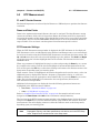
Chapter 8—Noise Floor Measurement
8-1
Introduction . . . . . . . . . . . . . . . . . . . . . . . . . . . . . . . . . . . . . . . . . . . . . . . . 8-1
8-2
Chapter Overview . . . . . . . . . . . . . . . . . . . . . . . . . . . . . . . . . . . . . . . . . . . . 8-1
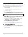
8-3
Noise Floor Measurement Setup
8-4
Performing the Noise Floor Test. . . . . . . . . . . . . . . . . . . . . . . . . . . . . . . . . 8-2
8-5
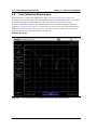
Noise Floor Measurements . . . . . . . . . . . . . . . . . . . . . . . . . . . . . . . . . . . . 8-3
Noise Floor Measurement with No External Interference . . . . . . . . . . . 8-3
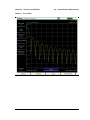
External Interference Example . . . . . . . . . . . . . . . . . . . . . . . . . . . . . . . 8-4
Saving a Noise Floor Measurement . . . . . . . . . . . . . . . . . . . . . . . . . . 8-4
8-6
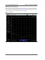
Menus . . . . . . . . . . . . . . . . . . . . . . . . . . . . . . . . . . . . . . . . . . . . . . . . . . . . . 8-5
Measurements Menu. . . . . . . . . . . . . . . . . . . . . . . . . . . . . . . . . . . . . . . 8-5
Noise Floor Menu . . . . . . . . . . . . . . . . . . . . . . . . . . . . . . . . . . . . . . . . . 8-5
. . . . . . . . . . . . . . . . . . . . . . . . . . . . . . 8-2
Chapter 9—Distance-to-PIM (DTP)
9-1
Introduction – Distance-to-PIM (DTP) Analyzer . . . . . . . . . . . . . . . . . . . . . 9-1
9-2
Chapter Overview . . . . . . . . . . . . . . . . . . . . . . . . . . . . . . . . . . . . . . . . . . . . 9-2
9-3
DTP Measurement . . . . . . . . . . . . . . . . . . . . . . . . . . . . . . . . . . . . . . . . . . . 9-3
F1 and F2 Carrier Sources . . . . . . . . . . . . . . . . . . . . . . . . . . . . . . . . . 9-3
Dmax and Data Points . . . . . . . . . . . . . . . . . . . . . . . . . . . . . . . . . . . . 9-3
DTP Parameter Settings . . . . . . . . . . . . . . . . . . . . . . . . . . . . . . . . . . . . 9-3
9-4
Post-Calibration Measurement . . . . . . . . . . . . . . . . . . . . . . . . . . . . . . . . 9-4
Measuring a Connected Load . . . . . . . . . . . . . . . . . . . . . . . . . . . . . . . . 9-6
9-5
DTP Measurement Setup
9-6
Making a DTP Measurement . . . . . . . . . . . . . . . . . . . . . . . . . . . . . . . . . 9-11
9-7
Trace Overlay
. . . . . . . . . . . . . . . . . . . . . . . . . . . . . . . . . . . . . . . . . . . 9-13
Line Sweep Tools . . . . . . . . . . . . . . . . . . . . . . . . . . . . . . . . . . . . . . . . 9-14
9-8
Enhanced Resolution
9-9
Menu Map 1 . . . . . . . . . . . . . . . . . . . . . . . . . . . . . . . . . . . . . . . . . . . . . . 9-17
. . . . . . . . . . . . . . . . . . . . . . . . . . . . . . . . . . 9-8
. . . . . . . . . . . . . . . . . . . . . . . . . . . . . . . . . . . . . . 9-15
9-10 Menu Map 2 . . . . . . . . . . . . . . . . . . . . . . . . . . . . . . . . . . . . . . . . . . . . . . 9-18
9-11 Distance Menu . . . . . . . . . . . . . . . . . . . . . . . . . . . . . . . . . . . . . . . . . . . . 9-19
9-12 DTP Aid Menu
. . . . . . . . . . . . . . . . . . . . . . . . . . . . . . . . . . . . . . . . . . . . 9-20
9-13 DTP Setup Menu
MW82119A UG
. . . . . . . . . . . . . . . . . . . . . . . . . . . . . . . . . . . . . . . . . 9-21
PN: 10580-00285 Rev. H
Contents-5
Table of Contents (Continued)
9-14 Cable List Menu
. . . . . . . . . . . . . . . . . . . . . . . . . . . . . . . . . . . . . . . . . . 9-22
Confirmation Clear All Favorites . . . . . . . . . . . . . . . . . . . . . . . . . . . . . 9-23
Cable List . . . . . . . . . . . . . . . . . . . . . . . . . . . . . . . . . . . . . . . . . . . . . 9-23
Favorites (in Cable List) . . . . . . . . . . . . . . . . . . . . . . . . . . . . . . . . . . 9-24
9-15 Windowing Menu
. . . . . . . . . . . . . . . . . . . . . . . . . . . . . . . . . . . . . . . . . . 9-25
9-16 DTP Amplitude Menu . . . . . . . . . . . . . . . . . . . . . . . . . . . . . . . . . . . . . . . 9-26
9-17 Setup Menu
. . . . . . . . . . . . . . . . . . . . . . . . . . . . . . . . . . . . . . . . . . . . . . 9-27
9-18 Units Menu . . . . . . . . . . . . . . . . . . . . . . . . . . . . . . . . . . . . . . . . . . . . . . . 9-28
Measurements Menu . . . . . . . . . . . . . . . . . . . . . . . . . . . . . . . . . . . . . . 9-28
9-19 Marker Menu
. . . . . . . . . . . . . . . . . . . . . . . . . . . . . . . . . . . . . . . . . . . . . 9-29
9-20 Resolution Menu . . . . . . . . . . . . . . . . . . . . . . . . . . . . . . . . . . . . . . . . . . . 9-30
9-21 Cable Menu . . . . . . . . . . . . . . . . . . . . . . . . . . . . . . . . . . . . . . . . . . . . . . . 9-30
DTP Parameters window . . . . . . . . . . . . . . . . . . . . . . . . . . . . . . . . . . . 9-30
9-22 Trace Submenu Key . . . . . . . . . . . . . . . . . . . . . . . . . . . . . . . . . . . . . . . . . 9-31
9-23 Reference (Limit) Menu . . . . . . . . . . . . . . . . . . . . . . . . . . . . . . . . . . . . . . 9-32
Chapter 10—Trace
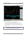
10-1 Introduction
. . . . . . . . . . . . . . . . . . . . . . . . . . . . . . . . . . . . . . . . . . . . . 10-1
10-2 Chapter Overview . . . . . . . . . . . . . . . . . . . . . . . . . . . . . . . . . . . . . . . . . . . 10-1
10-3 Trace Overlay Features . . . . . . . . . . . . . . . . . . . . . . . . . . . . . . . . . . . . . 10-1
Trace Comparison Example
. . . . . . . . . . . . . . . . . . . . . . . . . . . . . . 10-1
10-4 Trace Menu, Distance-to-PIM . . . . . . . . . . . . . . . . . . . . . . . . . . . . . . . . 10-3
Select Color Choice Box . . . . . . . . . . . . . . . . . . . . . . . . . . . . . . . . . 10-3
Valid Trace . . . . . . . . . . . . . . . . . . . . . . . . . . . . . . . . . . . . . . . . . . . . 10-3
Chapter 11—Swept PIM
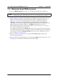
11-1 Introduction – Swept PIM Analyzer . . . . . . . . . . . . . . . . . . . . . . . . . . . . . 11-1
11-2 Chapter Overview . . . . . . . . . . . . . . . . . . . . . . . . . . . . . . . . . . . . . . . . . . . 11-1
11-3 Swept PIM Setup
. . . . . . . . . . . . . . . . . . . . . . . . . . . . . . . . . . . . . . . . . 11-2
Configure the PIM Test . . . . . . . . . . . . . . . . . . . . . . . . . . . . . . . . . . . 11-3
11-4 Making the Swept PIM Measurement
. . . . . . . . . . . . . . . . . . . . . . . . . . 11-4
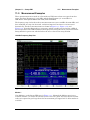
11-5 Measurement Examples . . . . . . . . . . . . . . . . . . . . . . . . . . . . . . . . . . . . . 11-5
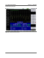
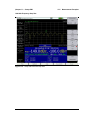
11-6 Swept PIM Measurement of Two PIM Sources . . . . . . . . . . . . . . . . . . . . 11-8
11-7 Menu Map
. . . . . . . . . . . . . . . . . . . . . . . . . . . . . . . . . . . . . . . . . . . . . . . 11-9
11-8 Frequency (Freq) Menu
. . . . . . . . . . . . . . . . . . . . . . . . . . . . . . . . . . . . 11-10
11-9 Amplitude Menu . . . . . . . . . . . . . . . . . . . . . . . . . . . . . . . . . . . . . . . . . . 11-11
11-10 Setup Menu
Contents-6
. . . . . . . . . . . . . . . . . . . . . . . . . . . . . . . . . . . . . . . . . . . . . 11-11
PN: 10580-00285 Rev. H
MW82119A UG
Table of Contents (Continued)
11-11 Marker Menu . . . . . . . . . . . . . . . . . . . . . . . . . . . . . . . . . . . . . . . . . . . . 11-12
Measurements Menu. . . . . . . . . . . . . . . . . . . . . . . . . . . . . . . . . . . . . 11-12
Chapter 12—PIM Analyzer Programming Commands
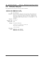
12-1 SCPI Commands Introduction . . . . . . . . . . . . . . . . . . . . . . . . . . . . . . . . . 12-1
12-2 Chapter Overview . . . . . . . . . . . . . . . . . . . . . . . . . . . . . . . . . . . . . . . . . . . 12-2
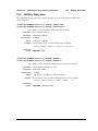
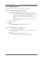
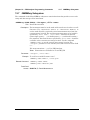
12-3 :CALCulate Subsystem. . . . . . . . . . . . . . . . . . . . . . . . . . . . . . . . . . . . . . . 12-3
12-4 :CALibration Subsystem . . . . . . . . . . . . . . . . . . . . . . . . . . . . . . . . . . . . . 12-18
12-5 :DISPlay Subsystem . . . . . . . . . . . . . . . . . . . . . . . . . . . . . . . . . . . . . . . . 12-19
12-6 :INITiate Subsystem . . . . . . . . . . . . . . . . . . . . . . . . . . . . . . . . . . . . . . . . 12-20
12-7 :MMEMory Subsystem . . . . . . . . . . . . . . . . . . . . . . . . . . . . . . . . . . . . . . 12-21
12-8 :SENSe Subsystem . . . . . . . . . . . . . . . . . . . . . . . . . . . . . . . . . . . . . . . . 12-24
12-9 :TRACe Subsystem . . . . . . . . . . . . . . . . . . . . . . . . . . . . . . . . . . . . . . . . 12-32
Chapter 13—All Modes Programming Commands
13-1 Chapter Overview . . . . . . . . . . . . . . . . . . . . . . . . . . . . . . . . . . . . . . . . . . . 13-1
13-2 :INSTrument Subsystem. . . . . . . . . . . . . . . . . . . . . . . . . . . . . . . . . . . . . . 13-2
13-3 :MMEMory Subsystem . . . . . . . . . . . . . . . . . . . . . . . . . . . . . . . . . . . . . . . 13-4
13-4 :SYSTem Subsystem . . . . . . . . . . . . . . . . . . . . . . . . . . . . . . . . . . . . . . . . 13-6
Appendix A—Other Documents
A-1
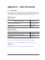
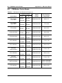
Introduction . . . . . . . . . . . . . . . . . . . . . . . . . . . . . . . . . . . . . . . . . . . . . . . . . A-1
PIM Master Options . . . . . . . . . . . . . . . . . . . . . . . . . . . . . . . . . . . . . . . A-1
Related Documents . . . . . . . . . . . . . . . . . . . . . . . . . . . . . . . . . . . . . . . A-1
Appendix B—PIM Carrier Bands
B-1
Introduction . . . . . . . . . . . . . . . . . . . . . . . . . . . . . . . . . . . . . . . . . . . . . . . . . B-1
B-2
PIM Master Carrier Bands
. . . . . . . . . . . . . . . . . . . . . . . . . . . . . . . . . . . B-2
Appendix C—Wireless Remote Control
C-1
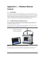
Introduction . . . . . . . . . . . . . . . . . . . . . . . . . . . . . . . . . . . . . . . . . . . . . . . . . C-1
C-2
Portable Router for Wireless Access . . . . . . . . . . . . . . . . . . . . . . . . . . . . . C-1
C-3
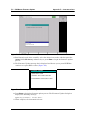
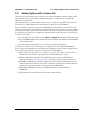
Configuring the PIM Master for Wireless Browser Control . . . . . . . . . . . . . C-2
C-4
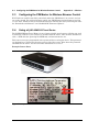
Using a ZyXEL MWR102 Travel Router . . . . . . . . . . . . . . . . . . . . . . . . . C-2
Connecting the Router to the PIM Master . . . . . . . . . . . . . . . . . . . . . . . C-3
Configuring PIM Master for use with Router . . . . . . . . . . . . . . . . . . . . . C-4
MW82119A UG
PN: 10580-00285 Rev. H
Contents-7
Table of Contents (Continued)
C-5
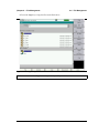
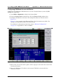
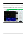
Remote Control via a Browser . . . . . . . . . . . . . . . . . . . . . . . . . . . . . . . . . .C-6
Screen Capture . . . . . . . . . . . . . . . . . . . . . . . . . . . . . . . . . . . . . . . . . . .C-7
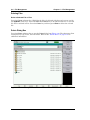
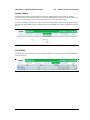
List of Files. . . . . . . . . . . . . . . . . . . . . . . . . . . . . . . . . . . . . . . . . . . . . . .C-7
Using Anritsu Line Sweep Tools . . . . . . . . . . . . . . . . . . . . . . . . . . . . . .C-8
Saving Measurements . . . . . . . . . . . . . . . . . . . . . . . . . . . . . . . . . . . . . .C-9
Password Protection . . . . . . . . . . . . . . . . . . . . . . . . . . . . . . . . . . . . . .C-11
Instrument Name . . . . . . . . . . . . . . . . . . . . . . . . . . . . . . . . . . . . . . . . .C-12
Appendix D—Instrument Messages and Errors
D-1
PIM Analyzer Warning Messages . . . . . . . . . . . . . . . . . . . . . . . . . . . . . . .D-1
D-2
Operation Error Messages . . . . . . . . . . . . . . . . . . . . . . . . . . . . . . . . . . . . .D-2
Error Messages Stop Current Measurements . . . . . . . . . . . . . . . . . . . .D-2
Appendix E—Windowing
E-1
Introduction . . . . . . . . . . . . . . . . . . . . . . . . . . . . . . . . . . . . . . . . . . . . . . . . E-1
E-2
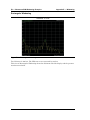
Distance-to-PIM Windowing Examples. . . . . . . . . . . . . . . . . . . . . . . . . . . . E-1
Rectangular Windowing . . . . . . . . . . . . . . . . . . . . . . . . . . . . . . . . . . . . E-2
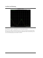
Nominal Side Lobe Windowing . . . . . . . . . . . . . . . . . . . . . . . . . . . . . . . E-3
Low Side Lobe Windowing . . . . . . . . . . . . . . . . . . . . . . . . . . . . . . . . . . E-4
Minimum Side Lobe Windowing . . . . . . . . . . . . . . . . . . . . . . . . . . . . . . E-5
Appendix F—Instrument Care
F-1
Introduction . . . . . . . . . . . . . . . . . . . . . . . . . . . . . . . . . . . . . . . . . . . . . . . . . F-1
Appendix Overview . . . . . . . . . . . . . . . . . . . . . . . . . . . . . . . . . . . . . . . . F-1
F-2
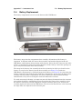
Preventive Maintenance
F-3
Battery Care . . . . . . . . . . . . . . . . . . . . . . . . . . . . . . . . . . . . . . . . . . . . . . . . F-2
F-4
Battery Replacement . . . . . . . . . . . . . . . . . . . . . . . . . . . . . . . . . . . . . . . . . F-3
F-5
PIM Master Firmware Update . . . . . . . . . . . . . . . . . . . . . . . . . . . . . . . . . . F-6
Determining the Firmware Version . . . . . . . . . . . . . . . . . . . . . . . . . . . . F-6
Downloading the Firmware . . . . . . . . . . . . . . . . . . . . . . . . . . . . . . . . . . F-6
Updating with a USB Memory Device . . . . . . . . . . . . . . . . . . . . . . . . . . F-7
F-6
Adding Options with a License File
. . . . . . . . . . . . . . . . . . . . . . . . . . . . . . . . . . . . . F-1
. . . . . . . . . . . . . . . . . . . . . . . . . . . . . F-9
Appendix G—LAN and DHCP
G-1
Introduction . . . . . . . . . . . . . . . . . . . . . . . . . . . . . . . . . . . . . . . . . . . . . . . .G-1
G-2
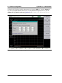
Ethernet Configuration . . . . . . . . . . . . . . . . . . . . . . . . . . . . . . . . . . . . . . . .G-1
LAN Connection . . . . . . . . . . . . . . . . . . . . . . . . . . . . . . . . . . . . . . . . . .G-1
Ethernet Config . . . . . . . . . . . . . . . . . . . . . . . . . . . . . . . . . . . . . . . . . . .G-3
Ethernet Menu . . . . . . . . . . . . . . . . . . . . . . . . . . . . . . . . . . . . . . . . . . .G-4
G-3
DHCP . . . . . . . . . . . . . . . . . . . . . . . . . . . . . . . . . . . . . . . . . . . . . . . . . . . . .G-5
Example 1 . . . . . . . . . . . . . . . . . . . . . . . . . . . . . . . . . . . . . . . . . . . . . . .G-5
Example 2 . . . . . . . . . . . . . . . . . . . . . . . . . . . . . . . . . . . . . . . . . . . . . . .G-6
Contents-8
PN: 10580-00285 Rev. H
MW82119A UG
G-4
ipconfig Tool . . . . . . . . . . . . . . . . . . . . . . . . . . . . . . . . . . . . . . . . . . . . . . .G-6
G-5
Ping Tool
. . . . . . . . . . . . . . . . . . . . . . . . . . . . . . . . . . . . . . . . . . . . . . . . .G-7
Index
MW82119A UG
PN: 10580-00285 Rev. H
Contents-9
Contents-10
PN: 10580-00285 Rev. H
MW82119A UG
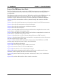
Chapter 1 — General Information
1-1
Introduction
This chapter provides a description of the Anritsu PIM Master, its available options and
accessories, a description of Passive Intermodulation (PIM) and how it is tested, and the
reasons for testing PIM.
Note
PIM testing is not a replacement for line sweeping but is an additional tool to test a
cellular system. PIM is a measure of system linearity as compared to line
sweeping, which is a measure of system impedance. Both tests are critical to
validate a cellular system.
Chapter Overview
This chapter contains the following sections:
• Section 1-2 “Contacting Anritsu” on page 1-3
• Section 1-3 “Anritsu Service Centers” on page 1-3
• Section 1-4 “Additional Documentation” on page 1-3
• Section 1-5 “PIM Master Options” on page 1-5
• Section 1-6 “PIM Master Performance Specifications” on page 1-5
• Section 1-7 “ESD Caution” on page 1-6
• Section 1-8 “Anritsu Line Sweep Tools (LST)” on page 1-6
• Section 1-9 “Wireless Remote Control of PIM Analyzer” on page 1-6
• Section 1-10 “PIM Master Firmware Update” on page 1-6
• Section 1-11 “PIM Master Option Update” on page 1-7
• Section 1-12 “Standard and Optional Accessories” on page 1-7
• Section 1-13 “What is PIM?” on page 1-7
• Section 1-14 “Why Test for PIM?” on page 1-9
• Section 1-15 “PIM Testing Procedure” on page 1-12
• Section 1-16 “Test Reports” on page 1-14
Note
Throughout this user guide, screen images are provided as examples. The image
and measurement details on your instrument may differ from the examples in this
user guide.
MW82119A UG MG PM
PN: 10580-00285 Rev. H
1-1
1-1
Introduction
Chapter 1 — General Information
Scope of the PIM Master User Guide
This User Guide describes the operation of the PIM Master battery operated PIM Analyzer
for performing PIM versus Time, Noise Floor, Distance-to-PIM (DTP), and Swept PIM
measurements.
This chapter provides a general overview of PIM analysis and the Anritsu PIM Master. It also
includes instructions on care and user maintenance, describes frequency range pairs,
illustrates a typical PIM analysis setup, and reviews updating the PIM Master firmware.
Chapter 2 provides an instrument overview, parameter setup, and connections for PIM
analysis.
Chapter 3 describes of initial parameter and connection setup for basic PIM measurements.
Chapter 4 describes file management and associated menus.
Chapter 5 describes the system menus and firmware updates.
Chapter 6 describes the GPS option.
Chapter 7 describes PIM versus Time analysis and includes a comprehensive review of the
menus that are available in this analyzer mode.
Chapter 9 describes Distance-to-PIM™ analysis and includes a comprehensive review of the
menus that are available in this analyzer mode.
Chapter 10 describes the use of Trace features during Distance-to-PIM™ analysis.
Chapter 11 describes Swept PIM analysis and includes a comprehensive review of the menus
that are available in this analyzer mode.
Chapter 12 lists available SCPI commands for remote setup of the PIM Master and PIM
Analyzer mode through the remote control of the PIM Master.
Appendix A lists reference documents.
Appendix B lists the frequency ranges of PIM carrier bands.
Appendix C describes remote access to the PIM Master.
Appendix D lists reference, error, and warning messages.
Appendix E describes windowing, which reduces side lobes by smoothing out the sharp
transitions at the beginning and end of a measurement sweep.
Appendix F provides instructions for preventive maintenance, battery care, and firmware
updates.
Appendix G provides additional data about network connections.
1-2
PN: 10580-00285 Rev. H
MW82119A UG MG PM
Chapter 1 — General Information
1-2
1-2
Contacting Anritsu
Contacting Anritsu
To contact Anritsu, please visit:
http://www.anritsu.com/contact.asp
Here, you can find sales, customer service, and support contact information for your country
or region, provide online feedback, complete a “Talk to Anritsu” form to have your questions
answered, or obtain other services offered by Anritsu.
Updated product information can be found on the Anritsu web site:
http://www.anritsu.com/
Search for the product model number. The latest documentation is on the product page under
the Library tab.
Example URL for MW82119A:
http://www.anritsu.com/en-us/products-solutions/products/MW82119A.aspx
1-3
Anritsu Service Centers
For the latest service and sales information in your area, please visit the following URL:
http://www.anritsu.com/contact.asp
and choose a country for regional contact information.
1-4
Additional Documentation
Refer to the PIM Master Product Brochure (part number: 11410-00679) for specifications and
options data. Refer to Appendix A for other related documents.
MW82119A UG MG PM
PN: 10580-00285 Rev. H
1-3
1-4
Additional Documentation
Chapter 1 — General Information
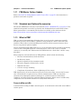
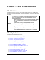
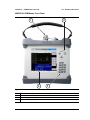
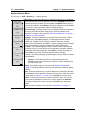
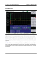
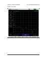
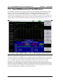
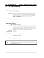
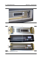
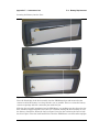
The PIM Master
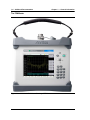
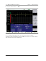
Figure 1-1.
1-4
MW82119A PIM Master Showing a DTP Measurement
PN: 10580-00285 Rev. H
MW82119A UG MG PM
Chapter 1 — General Information
1-5
1-5
PIM Master Options
PIM Master Options
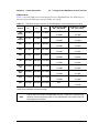
Table 1-1 lists the current available options. Refer to the Anritsu web site for the latest
information on available PIM Master options and frequency ranges.
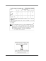
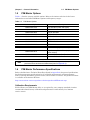
Table 1-1.
PIM Master Options
Instrument Option
Note
1-6
Description
MW82119A-0700
LTE 700 MHz (Lower and Upper)
MW82119A-0800
LTE 800 MHz
MW82119A-0850
Cellular 850 MHz
MW82119A-0900
E-GSM 900 MHz
MW82119A-0180
DCS 1800 MHz
MW82119A-0193
PCS/AWS 1900/2100 MHz
MW82119A-0210
UMTS 2100 MHz
MW82119A-0260
LTE 2600 MHz
MW82119A-0031
GPS Receiver (requires antenna)
MW82119A-0019
High Accuracy Power Meter (requires external
power sensor)
MW82119A-0098
Standard Calibration Certification
MW82119A-0099
Premium Calibration Certification
For ordering information and for option and accessory part numbers, refer to the
product brochure and technical data sheet (listed in Appendix A).
PIM Master Performance Specifications
Refer to the Brochure / Technical Data Sheet (listed in Appendix A) for general specifications,
detailed measurement specifications for all available measurements and measurement
modes, ordering information, powers sensors, and available accessories. The product brochure
is available on the Anritsu Web site:
http://www.anritsu.com/en-us/products-solutions/products/MW82119A.aspx
Calibration Requirements
Field calibrate your PIM Master daily, or as required by your company standards. Anritsu
recommends annual factory calibration and performance verification by local Anritsu
service centers.
MW82119A UG MG PM
PN: 10580-00285 Rev. H
1-5
1-7
ESD Caution
1-7
Chapter 1 — General Information
ESD Caution
The PIM Master, like other high performance instruments, is susceptible to electrostatic
discharge (ESD) damage. Coaxial cables and antennas often build up a static charge, which
(if allowed to discharge by connecting directly to the PIM Master without discharging the
static charge) may damage the PIM Master input circuitry.
Caution
Operators must be aware of the potential for ESD damage and take all necessary
precautions.
Operators should exercise practices outlined within industry standards such as JEDEC-625
(EIA-625), MIL-HDBK-263, and MIL-STD-1686, which pertain to ESD and ESDS devices,
equipment, and practices. Because these apply to the PIM Master, Anritsu recommends that
any static charges that may be present be dissipated before connecting coaxial cables or
antennas to the PIM Master. This may be as simple as temporarily attaching a short or load
device to the cable or antenna prior to attaching to the PIM Master. It is important to
remember that the operator may also carry a static charge. Following the practices outlined
in the above standards will ensure a safe environment for both personnel and equipment.
1-8
Anritsu Line Sweep Tools (LST)
Anritsu Line Sweep Tools is a PC software program that is used for report generation and
post-task analysis. A PC equipped with LST can download measurement data directly from
the instruments or from a USB memory device (if you saved measurements on, or transferred
them to, a USB memory device). A complete suite of computer software applications
(including LST) are available for download:
http://www.anritsu.com/en-US/Services-Support/Handheld-Tools-Tool-Box.aspx
1-9
Wireless Remote Control of PIM Analyzer
Browser based control allows you to remotely control the PIM Master from any Wi-Fi enabled
device with web browser software. This includes a wide range of tablets and phones running
Android or iOS operating systems as well as the traditional Linux and Windows laptop and
desktop computers.
Wi-Fi links are useful in the field, particularly when the PIM Master is on a tower, and you
are on the ground.
For wireless remote control, a Wi-Fi router must be connected to the PIM Master.
Refer to Appendix C, “Wireless Remote Control” for more details on using this capability to
enable wireless control.
1-10
PIM Master Firmware Update
Refer to Section F-5 “PIM Master Firmware Update” on page F-6 for firmware upgrade
procedures.
1-6
PN: 10580-00285 Rev. H
MW82119A UG MG PM
Chapter 1 — General Information
1-11
1-11
PIM Master Option Update
PIM Master Option Update
Refer to Section F-6 “Adding Options with a License File” on page F-9 for instructions to
purchase and enable an option.
1-12
Standard and Optional Accessories
The Anritsu PIM Master warranty is described in Section “WARRANTY” on page TG-3. The
standard and optional accessories are listed in the Product Brochure and Technical Data
Sheet (part number 11410-00679). The brochure is available on the Anritsu web site:
http://www.anritsu.com/en-us/products-solutions/products/MW82119A.aspx
1-13
What is PIM?
PIM is a form of intermodulation distortion that occurs in passive components normally
thought of as linear, such as filters, combiners, surge protectors, cables, connectors, and
antennas. When subject to the high RF powers found in cellular systems, however, these
devices can generate spurious signals.
Passive Intermodulation (PIM) shows up as a set of unwanted signals created by the mixing
of two or more strong RF signals in a non-linear device, such as in a loose or corroded
connector, or in nearby rust. Other names for PIM include the “diode effect” and the “rusty
bolt effect”.
Many symptoms could be indicators of PIM problems, which include the following:
• Receiver desensitization (raised noise floor)
• Rx Diversity alarms
• Spectral regrowth in the transmitter mask
• Excessive dropped or blocked calls, or both
• Reduced data rates
• Cell site coverage shrinking
• Complaints of interference from neighboring cell site owners
PIM signals in the cell receive band can raise the receive noise floor, increase the bit error
rate, and shrink the reception area for cellular communications. PIM can come from
junctions; from improperly tightened, damaged, or corroded connectors; from filters,
combiners, and surge protectors; and from damaged antennas. Other sources include rusty
components, such as mounts and bolts or nearby metal structures.
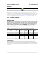
Power in dBm and dBc
A measurement reading in dBm is absolute power. A measurement value with units of dBc is
relative power.
MW82119A UG MG PM
PN: 10580-00285 Rev. H
1-7
1-13
What is PIM?
Chapter 1 — General Information
For example, if you set TX1 and TX2 to 43 dBm and get a measurement result of –120 dBm
(the measurement result as absolute power), this represents a relative power of –163 dBc.
The calculation is as follows:
–120 dBm – 43 dBm = –163 dBc
[measured power in dBm] minus [transmitted power in dBm]
equals [relative power in dBc]
The term relative power, in this example, is referring to the original output power setting of
43 dBm. When stated in units of dBc, the received PIM power is relative to (is being compared
to) the transmitted power level of one test tone. The difference between the transmitted
power (in dBm) and the measured PIM power (in dBm) is the relative power, which is then
expressed in units of dBc.
Note
1-8
The use of dBc units is not applicable to Noise Floor measurements, because the
transmitters are not On during this measurement.
PN: 10580-00285 Rev. H
MW82119A UG MG PM
Chapter 1 — General Information
1-14
1-14
Why Test for PIM?
Why Test for PIM?
Anritsu has developed the PIM Master to verify and troubleshoot Passive Intermodulation
(PIM). The PIM Master generates two high-power tones, usually in the transmit band of
interest. It displays and measures the third-order, fifth-order, or seventh-order
intermodulation products returning from the DUT to the PIM Master. (The third, fifth, and
seventh-order intermodulation products can be measured only if they fall into the range of the
receive band.) Using Distance-to-PIM technology, the PIM Master can identify the location of
PIM sources both inside the antenna system and beyond.
PIM testing provides a measurement of the overall linearity of the antenna system and the
surrounding environment. A formula for determining third order intermodulation (IM3)
frequencies is provided in section “Intermodulation Distortion” on page 1-11.
When more carriers are added to a site and transmit power is increased, the impact of PIM on
site performance becomes more severe. A low-traffic may not exhibit the same performance
problems as a busy site.
Line Sweeping and PIM testing
Line Sweep testing and PIM testing are very different tests. Both are very important and
accurate measures of the ability of the cell site to provide service and to perform optimally.
PIM testing measurements indicate the overall linearity of an antenna feed line, the antenna,
and the area illuminated by the transmitted signal. The Line Sweep measurements indicate
the overall impedance matching of all of the components in an antenna feed line. Both tests
need to be performed in order to ensure the overall quality on a site.
PIM testing requires both low system loss and good return loss (VSWR) to achieve an
accurate measurement. If PIM testing is performed prior to line sweep testing, then you may
not be aware of the impedance characteristics of the transmission line. High insertion loss
attenuates the PIM test signals, which prevents full test power from reaching the specific
components that require stringent PIM testing. Poor return loss reflects a percentage of the
PIM test signals back into the test set, which causes some signal cancellation that can report
a false pass. In other words, poor line sweep performance can lead to a false pass for a PIM
test.
By performing the line sweep test prior to PIM testing, you can be confident the insertion loss
and return loss data are at acceptable levels. This data in turn ensures that the PIM test
signals actually reach all components at the correct signal level, offering the most accurate
indicator of true PIM performance. By constructing a system using modern low PIM
practices, the need to break the transmission system back open will be minimized. If the lines
are disassembled again to repair or clean a connector, the line sweep and PIM testing will
need to be repeated.
Causes of PIM
PIM is caused by two or more strong RF signals mixing in a non-linear device. These
non-linear devices, or junctions, occur in improperly tightened, damaged, or corroded
connectors or in damaged antennas. Rusty components, such as mounts and bolts, are also
suspect when hunting for sources of PIM.
MW82119A UG MG PM
PN: 10580-00285 Rev. H
1-9
1-14
Why Test for PIM?
Chapter 1 — General Information
PIM can be generated anywhere in the RF path. The RF path includes not only the antenna
feed system but also the antenna itself, as well as objects illuminated by the antenna.
Because RF currents are strongest inside the coaxial cables and physically close to the
antenna radiating aperture, non-linear junctions or materials in these locations are more
likely to generate harmful PIM than non-linearities away from these regions.
The following list provides guidelines for preventing PIM at cellular installations:
• Visually inspect RF connectors and RF cables before assembly to remove all metal
flakes.
• Verify that RF mating surfaces are clean and free of mechanical damage prior to
assembly.
• Wipe mating surfaces with a lint-free wipe, moistened with alcohol to remove dirt and
oils.
• Face coaxial cables downward while cutting so that any metal flakes that are produced
fall out rather than into the coaxial cable.
• Always use sharp cutting tools when preparing the ends of coaxial cables.
• Use the correct cable preparation tools for the type and size coaxial cable with which
you are working.
• Remove any metal burs from the cut edges of coaxial cables prior to connector
attachment.
• Prevent foam dielectric material from getting trapped between metal contacting
surfaces.
• Remove all adhesive residue from the mating region of the coaxial cable center
conductor.
• Properly align RF connectors prior to assembly in order to prevent damage to mating
surfaces.
• Apply the torque that is specified by the manufacturer to all mated pairs of RF
connectors.
• Do not over-torque RF connectors because doing so may cause damage to contacting
surfaces.
• Prevent excessive vibration and shock to RF components when transporting them to
the site.
• Prevent RF components from impacting the tower while hoisting.
• Leave protective caps on RF connectors until you are ready to attach the mating cable.
• Avoid loose metal objects within the half-power beamwidths of basestation antennas,
cable trays, vent pipes, air conditioning units, metal flashing, guy wires, and so forth.
1-10
PN: 10580-00285 Rev. H
MW82119A UG MG PM
Chapter 1 — General Information
1-14
Why Test for PIM?
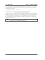
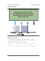
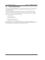
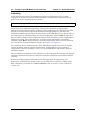
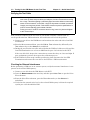
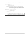
PIM Testing Example
Passive Device goes Non-linear,
Intermodulates the Two Frequencies,
Generates PIM Product in Rx band,
Raises Noise Floor.
R
Rx
x
1850 1870
Tx
1910 1930
1990
PCS Band (MHz)
Figure 1-2.
PCS Band PIM Testing
Intermodulation Distortion
The intermodulation distortion (IMx) is a mathematical function of F1 and F2.
3rd Order Intermodulation (IM3) = 2F1 – F2 or
(IM3) = 2F2 – F1
Finding IM3 when F1 = 1930 MHz and F2 = 1990 MHz:
IM3 = 2F1 – F2 = 2(1930) – 1990 = 1870 MHz (within Rx band)
or
IM3 = 2F2 – F1 = 2(1990) – 1930 = 2050 MHz (not within Rx band)
MW82119A UG MG PM
PN: 10580-00285 Rev. H
1-11
1-15
1-15
PIM Testing Procedure
Chapter 1 — General Information
PIM Testing Procedure
Before testing for PIM, ensure that line sweeping has been performed so that you can be
confident that the insertion loss and return loss data are at acceptable levels. These results
ensure that the PIM test signals actually reach all components at the correct signal level, and
therefore offer the most accurate indication of true PIM performance.
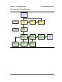
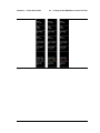
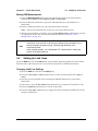
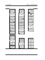
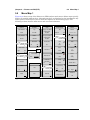
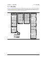
See Figure 1-3 on page 1-13 for a work flow chart of the recommended site testing procedure.
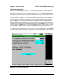
Typically, a PIM versus Time test is used to certify PIM performance. Anritsu recommends
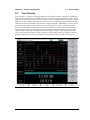
that you perform a Noise Floor measurement before you begin PIM testing. Refer to
Chapter 7, “PIM versus Time” and Chapter 8, “Noise Floor Measurement” for setup and
measurement procedures. The Noise Floor test is basically a PIM versus Time measurement
with the PIM transmit tones turned off and the PIM Master receiver activated.
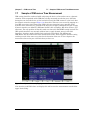
The Noise Floor measurement reveals external signals from mobile subscribers that might
interfere with your PIM measurement. If high interference is found, then adjust your F1 or
F2 test signals. This will shift the IM3 frequency and may provide you with a clear IM3
frequency for the PIM versus Time measurement. See Figure 1-2 on page 1-11.
After the IM3 frequency has been verified to be clear of interference, perform a PIM versus
Time measurement to search for any static PIM sources.
If static PIM sources are found that exceed the pass / fail criteria, then use Distance-to-PIM
(DTP) to locate and eliminate these static PIM sources. If DTP identifies multiple PIM
sources, then correct the largest magnitude fault and repeat the DTP measurement. Repeat
this process until magnitudes of all reported PIM faults appear acceptable.
Return to PIM vs. Time and perform a dynamic PIM test to verify that all RF connections and
components are robust. A dynamic PIM test involves lightly tapping on all RF connections
and components in the system while measuring PIM versus Time. If the peak PIM observed
during the dynamic test is below the customer's pass/fail threshold, then save the
measurement.
1-12
PN: 10580-00285 Rev. H
MW82119A UG MG PM
Chapter 1 — General Information
1-15
PIM Testing Procedure
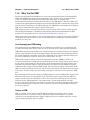
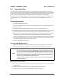
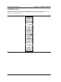
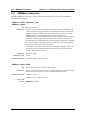
Recommended Testing Procedure
Start
Site Master
Sweep
Test
PIM Master
Noise
Floor
Repair
Figure 1-3.
DTF
Repair
Static
PIM vs.
Time
Dynamic
PIM vs.
Time
Save
Results
DTP
Repair
End
Recommended Testing Procedure Work Flow
MW82119A UG MG PM
PN: 10580-00285 Rev. H
1-13
1-16
1-16
Test Reports
Chapter 1 — General Information
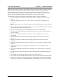
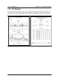
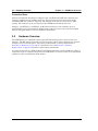
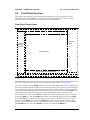
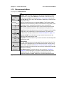
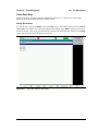
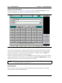
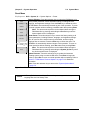
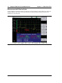
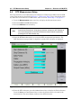
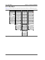
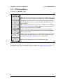
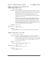
Test Reports
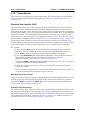
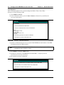
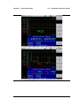
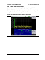
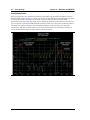
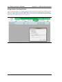
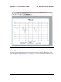
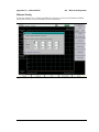
Use Line Sweep Tools (LST) to view and create reports from saved PIM measurements. Line
Sweep Tools can generate a standard report showing plots of the measured results. LST can
also generate a special PIM report to display PIM versus TIME results in a tabular format.
Figure 1-4.
1-14
Example Report Formats
PN: 10580-00285 Rev. H
MW82119A UG MG PM
Chapter 2 — PIM Master Overview
2-1
Introduction
This chapter provides a description of the MW82119A PIM Master. It also includes a brief
description of preventive maintenance, calibration requirements, and additional PIM Master
documents.
The Anritsu PIM Master is capable of producing 80 Watts of RF power in the
cellular communications bands. Users must take precautions to minimize
exposure to these RF fields:
Always terminate the output port of the test equipment into a load, a loaded
line, or a line that will radiate or absorb the energy before beginning a
PIM test.
Warning
Confirm that the PIM Master RF power is off after a PIM test.
Always confirm that the RF power is off before disconnecting a coaxial
connection, otherwise RF burns may result. Immediate burns to fingers or
eyes can result from exposure to live connectors.
RF power can be immediately turned off with the Emergency Stop button
(item 3 in Figure 2-4 on page 2-9).
Ensure that all antennas under test are placed so that no personnel are
exposed to RF levels that exceed the maximum allowable exposure.
2-2
Chapter Overview
This chapter contains the following sections:
• Section 2-3 “Instrument Description” on page 2-2
• Section 2-4 “Connector Care” on page 2-3
• Section 2-5 “Hardware Overview” on page 2-4
• Section 2-6 “Front Panel Keys” on page 2-7
• Section 2-7 “Top Connector Panel” on page 2-9
• Section 2-8 “Side Panel Connectors” on page 2-10
• Section 2-9 “Front Panel Overview” on page 2-13
• Section 2-10 “Mode Selector Menu” on page 2-18
• Section 2-11 “Secondary Function Menus” on page 2-19
• Section 2-12 “Touch Screen” on page 2-20
• Section 2-13 “Touch Screen Calibration” on page 2-24
• Section 2-14 “Parameter Setting” on page 2-25
• Section 2-15 “Symbols and Indicators” on page 2-26
• Section 2-16 “Firmware Overview” on page 2-27
MW82119A UG
PN: 10580-00285 Rev. H
2-1
2-3
2-3
Instrument Description
Chapter 2 — PIM Master Overview
Instrument Description
Anritsu has developed the PIM Master to verify if receiver interference at a cell site is due to
an intermodulation product of two or more transmit frequencies, also known as passive
intermodulation (PIM).
The Anritsu PIM Master features patented technology – Distance-to-PIM. In just a few
seconds, Distance-to-PIM can find the distance and relative magnitude of all static PIM
sources in an antenna system and beyond the antenna. For example, Distance-to-PIM can
find the location of the following fault conditions:
• Dirty connectors
• Corroded connectors
• Over torqued connectors
• Microscopic arcing connectors
• PIM outside the antenna system
PIM is power sensitive, and as signal technologies develop, more power continues to be
transmitted at cell sites. The PIM Master features up to 2 x 40 Watts of RF power to activate
sources of PIM in the feed system as well as beyond the antenna.
2-2
PN: 10580-00285 Rev. H
MW82119A UG
Chapter 2 — PIM Master Overview
2-4
2-4
Connector Care
Connector Care
Visually inspect connectors for general wear, for cleanliness, and for damage such as bent
pins or connector rings. Repair or replace damaged connectors immediately. Inspect and clean
all RF connectors to remove metal flakes and contamination. Dirty connectors can limit the
accuracy of your measurements. Damaged connectors can damage the instrument.
Connection of cables with inadequate torque settings can affect measurement accuracy. Over
torquing connectors can damage the cable, the connector, the instrument, or all of these
items.
Connecting Procedure
1. Carefully align the connectors.
The male connector center pin must slip concentrically into the contact fingers of the
female connector.
2. Push connectors straight together. Do not twist or screw them together.
3. To tighten, turn the connector nut, not the connector body. Major damage can occur to
the center conductor and to the outer conductor if the connector body is twisted.
4. When you use a torque wrench, initially tighten by hand so that approximately 1/8 turn
or 45 degrees of rotation remains for the final tightening with the torque wrench.
Relieve any side pressure on the connection (such as from long or heavy cables) in order
to assure consistent torque. Use an open-end wrench to keep the connector body from
turning while tightening with the torque wrench.
Do not over torque the connector.
Test Cable from PIM Master to DUT
Remove o-rings from the test cable and be sure that the connectors are clean. If the
DUT connector has an o-ring, then use a torque wrench to tighten the connector.
Note
When testing, cables are connected and disconnected many times. In order to
save wear on these test cables and RF adapters, Anritsu recommends removing
the o-rings. This allows getting a sufficiently tight connection without unnecessary
stress on the connectors. In the field, o-rings are important to maintain connection
integrity over long time periods. Connections must be torqued to specifications in
order to ensure that they prevent water intrusion.
During your test, if the DUT connector has an o-ring, leave it in place and tighten
to the correct torque.
Disconnecting Procedure
1. Use an open-end wrench to keep the connector body from turning while loosening with a
second wrench.
2. Complete the disconnection by hand, turning only the connector nut.
3. Pull the connectors straight apart without twisting or bending.
MW82119A UG
PN: 10580-00285 Rev. H
2-3
2-5
Hardware Overview
Chapter 2 — PIM Master Overview
Connector Saver
Anritsu recommends attaching an adapter to the 7/16 DIN female RF Out connector and
using the adapter for the working connector. This connector saver reduces wear on the
instrument RF Out connector. Typically, 500 matings is the life of a connector for PIM
testing. The connector saver can remain on the PIM Master inside the soft case.
Adapter: 7/16 DIN(f) to 7/16 DIN(m), 50 Ω (Connector Saver). One connector saver is
provided with your test instrument. Replacement connector savers can be purchased from
Anritsu. The part number is in your Technical Data Sheet.
2-5
Hardware Overview
The PIM Master is a handheld, battery-operated PIM analyzer with a touch screen user
interface. The RF output connector is on the top panel, and all other connectors are located
behind a cover on the side panel. The battery compartment is on the bottom. Refer to
Section F-3 “Battery Care” on page F-2 for battery care and Section F-4 “Battery
Replacement” on page F-3 for battery replacement instructions.
Accessory items such as a PIM standard, Low PIM termination, and Low PIM test cable are
required in order to calibrate and operate the PIM Master. Accessory items can be purchased
together in a kit or individually from Anritsu.
2-4
PN: 10580-00285 Rev. H
MW82119A UG
Chapter 2 — PIM Master Overview
2-5
Hardware Overview
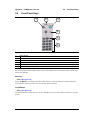
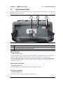
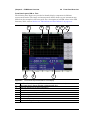
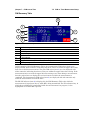
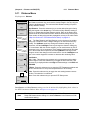
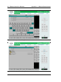
MW82119A PIM Master Front Panel
2
1
4
Figure 2-1.
1.
2.
3.
4.
3
MW82119A PIM Master Front Panel
RF Out Connector (connector saver attached), 7/16 DIN, female, 50 Ω
On/Off Button
Number Keypad
Measurement Display (a Touch Screen)
MW82119A UG
PN: 10580-00285 Rev. H
2-5
2-5
Hardware Overview
Chapter 2 — PIM Master Overview
RF Out Connector
(item 1 in Figure 2-1)
The PIM Master fits into its soft carrying case and transit case with a 7/16 DIN, female, 50 Ω
connector saver attached. Refer to “Connector Saver” on page 2-4 and “RF Out Connector”
on page 2-9.
On/Off Button
(item 2 in Figure 2-1)
Press to turn On the PIM Master. Press and hold to turn Off the PIM Master.
Number Keypad
(item 3 in Figure 2-1)
Refer to “Number Keypad” on page 2-8.
Measurement Display
(item 4 in Figure 2-1)
Touch Screen information begins in Section 2-12 “Touch Screen” on page 2-20.
Other Features On The Front Panel
Battery Charge LED (Green)
The Battery Charge LED flashes if the battery is charging, and remains on steady when the
battery is fully charged.
Power LED (Green)
The Power LED remains on when the PIM Master is on.
Features not shown in Figure 2-1
Battery Compartment
The battery compartment access is on the bottom of the PIM Master. Refer to
Section F-4 “Battery Replacement” on page F-3.
2-6
PN: 10580-00285 Rev. H
MW82119A UG
Chapter 2 — PIM Master Overview
2-6
2-6
Front Panel Keys
Front Panel Keys
2
1
3
4
5
6
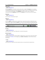
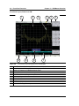
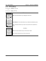
Figure 2-2.
1.
2.
3.
4.
5.
6.
Front Panel Layout
Menu Button
Speaker Grill
On/Off Button
Arrow Keys and Enter Key in center
Shift Key and Escape Key
Number Keypad
The terms button and hard key refer to all of the buttons on the instrument face. These keys
perform as follows:
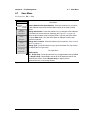
Menu Key
(item 1 in Figure 2-2)
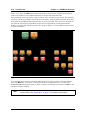
Press the Menu key to display the Menu Key Screen, a grid of shortcut icons for installed
measurement modes and user-selected menus and setup files.
On/Off Button
(item 3 in Figure 2-2)
Press this button to turn on power to the PIM Master. Press and hold this button to turn off
power.
MW82119A UG
PN: 10580-00285 Rev. H
2-7
2-6
Front Panel Keys
Chapter 2 — PIM Master Overview
Arrow Keys
(item 4 in Figure 2-2)
The four Arrow keys are used to scroll up, down, left, or right. The Arrow keys can often be
used (depending upon measurement selection) to change a value or to change a selection from
a list. In some measurements, the Left/Right arrow keys change values by different
increments than the Up/Down arrow keys. The Arrow keys are also used to move markers.
Enter Key
(item 4 in Figure 2-2)
Press this key to finalize data input.
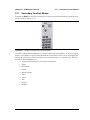
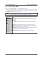
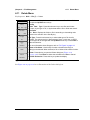
Shift Key
(item 5 in Figure 2-2)
Press the Shift key and then press a number key to open the menu that is indicated in text
above the key number. When the Shift key is active, its icon is displayed at the top-right of the
measurement display area between the battery charge indicator and the submenu key labels.
Figure 2-3.
Shift Key Icon
Esc Key
(item 5 in Figure 2-2)
Press this key to cancel any setting that is currently being made.
Number Keypad
(item 6 in Figure 2-2)
Press these keys to directly input numbers. Number keys are also used to open menus when
used with the “Shift Key”. For example, press Shift and Touch (0) to initiate Touch Screen
Calibration.
+/– Key
(item 6 in Figure 2-2)
Press this key to change the sign of numbers that are entered with the number keys.
2-8
PN: 10580-00285 Rev. H
MW82119A UG
Chapter 2 — PIM Master Overview
2-7
2-7
Top Connector Panel
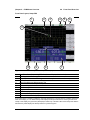
Top Connector Panel
The top connector panel includes the test port connector, the Radio Frequency ON light, and
the Emergency Stop button.
1
Figure 2-4.
1.
2.
3.
2
3
PIM Master Connection Diagram – Top
RF Out Connector, 7/16 DIN, female, 50 Ω
Indicator Light for RF On (Green)
Emergency Stop Button (turns Off RF output)
RF Out Connector
(item 1 in Figure 2-4)
Type 7/16 DIN(f), 50 Ω connector. To prevent damage to your instrument, do not use pliers or
a plain wrench to tighten the DIN connector. Do not overtighten the connector. The
recommended torque is 25 N·m (~18 lbf·ft). To prevent rotation, secure the RF Out connector
or the recommended connector saver (“Connector Saver” on page 2-4) with a wrench when
attaching a test lead.
Radio Frequency ON Light
(item 2 in Figure 2-4)
This green indicator is illuminated when RF output power is On.
Emergency Stop Button
(item 3 in Figure 2-4)
Press this red button to turn Off the RF output power.
MW82119A UG
PN: 10580-00285 Rev. H
2-9
2-8
2-8
Side Panel Connectors
Chapter 2 — PIM Master Overview
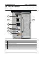
Side Panel Connectors
The side connector panel includes connectors for External Power, Ethernet/LAN, USB
interface, and GPS.
1
2
8
3
4
5
6
7
Figure 2-5.
1.
2.
3.
4.
5.
6.
7.
8.
2-10
Side Panel Overview
External Power
LAN Connection, RJ45
USB Interface, Type A
USB Interface, 5-pin mini-B
Auxiliary 1 (factory use only)
Auxiliary 2 (factory use only)
GPS Connector, SMA female (with Option 31)
Legend (icons identify connection types)
PN: 10580-00285 Rev. H
MW82119A UG
Chapter 2 — PIM Master Overview
2-8
Side Panel Connectors
External Power
(item 1 in Figure 2-5)
This 2.1 mm by 5.5 mm barrel connector is used to power the unit and for battery charging.
Input is 12 VDC to 15 VDC at up to 5.0 A. A green flashing indicator light near the power
switch shows that the instrument battery is being charged by the external charging unit. The
indicator is steadily illuminated when the battery is fully charged.
Warning
When using the AC-DC Adapter, always use a three-wire power cable that is
connected to a three-wire power line outlet. If power is supplied without grounding
the equipment in this manner, then the user is at risk of receiving a severe or fatal
electric shock.
LAN Connection
(item 2 in Figure 2-5)
The RJ45 connector is used to connect the PIM Master to a local area network. Integrated
into this connector are two LEDs. The amber LED shows the presence of a 10 Mbit/s LAN
connection when on, and a 100 Mbit/s LAN connection when off. The green LED flashes to
show that LAN traffic is present. For additional information about the LAN connection,
Ethernet connection, and DHCP, refer to Appendix G, “LAN and DHCP”.
USB Interface – Type A
(item 3 in Figure 2-5)
This interface has two connectors for flash drive and USB Power Sensor. The MW82119A
PIM Master can also be a USB Host and allow various USB Flash Memory devices to be
connected to the instrument for storing measurements, setups, files, and firmware upgrades.
Either USB connection can be used with a USB power sensor (but only one power sensor at a
time).
USB Interface – Type Mini-B
(item 4 in Figure 2-5)
The USB 2.0 interface can be used to connect the MW82119A PIM Master directly to a PC for
data transfer. The first time the PIM Master is connected to a PC, the normal USB device
detection by the computer operating system will take place. The CD-ROM that shipped with
the instrument contains a driver for Windows XP (or later) that is installed when Line Sweep
Tools is installed. Drivers are not available for earlier versions of the Windows operating
system. During the driver installation process, place the CD-ROM in the computer drive and
specify that the installation wizard should search the CD-ROM for the driver.
Note
For proper detection, Line Sweep Tools should be installed on the PC prior to
connecting the PIM Master to the USB port.
MW82119A UG
PN: 10580-00285 Rev. H
2-11
2-8
Side Panel Connectors
Chapter 2 — PIM Master Overview
GPS Antenna Connector (Option 31)
(item 7 in Figure 2-5)
The GPS antenna connection on the PIM Master is type SMA(F). Selectable +3 VDC or
+5 VDC antenna power.
To prevent damage to your instrument, do not use pliers or a plain wrench to tighten the
SMA connector. Do not overtighten the connector. The recommended torque is 8 lbf·in
(0.9 N·m or 90 N·cm).
2-12
PN: 10580-00285 Rev. H
MW82119A UG
Chapter 2 — PIM Master Overview
2-9
2-9
Front Panel Overview
Front Panel Overview
Throughout this manual, typical measurement displays are shown for the basic PIM
Analyzer mode of the PIM Master. Note that the images shown in this manual may be
different from any images that are displayed on your PIM Master.
Front Panel Display Areas
Date/Time
GPS
Battery Indicator
Measurement Title Area
Submenu
Keys
Instrument
Settings
Summary
Main Graph Area
Numerical Measurement Result Area
Main Menu Keys
Figure 2-6.
Front Panel Overview
The PIM Master menu-driven interface is easy to use and requires little training. Main menu
keys on the front panel are used to initiate function-specific menus. See Figure 2-1.
All of the hard keys and an On/Off button are located to the right of the measurement display.
Ten of the hard keys (0 through 9 in the number keypad) are dual purpose, depending upon
the current mode of operation. The dual-purpose keys are labeled with a number on the key
itself and with the alternate function printed on the key above the number. The Shift key is
above the number keypad and is used to access the functions that are printed on the
nine number keys. The escape (Esc) key (which is used for aborting data entry) is located
next to the Shift key. The four Arrow keys (above the number keypad) surround the Enter
key. The Arrow keys and the number keypad can be used to change the value of an active
parameter. The Menu key is above the Arrow keys and is used to display the Menu Key
Screen, a grid of shortcut icons for installed measurement modes and user-selected menus.
The On/Off button is above the Arrow keys and to the right of the Menu key.
MW82119A UG
PN: 10580-00285 Rev. H
2-13
2-9
Front Panel Overview
Chapter 2 — PIM Master Overview
Arranged in a vertical column along the right edge of the measurement display are
8 submenu keys. They change function depending upon the current menu selection. The
current submenu key function is indicated in the active function block (submenu key labels)
on the right edge and within the measurement display. An example of the keys is shown in
Figure 2-7 on page 2-15.
2-14
PN: 10580-00285 Rev. H
MW82119A UG
Chapter 2 — PIM Master Overview
2-9
Front Panel Overview
Front Panel Layout, PIM vs. Time
The following three figures are provided to identify display components in different
measurement modes. The image and measurement details shown on your instrument may
differ from the examples in this user guide. For a description of red PIM values in the PIM
Summary Table, refer to Section 3-5 “Limit Alarm and Pass Indicator” on page 3-14.
2-
2
1
9
Figure 2-7.
1.
2.
3.
4.
5.
6.
7.
8.
9.
8
4
3
5
6
7
Front Panel Layout with PIM vs. Time Display
Real Time Clock (followed by GPS Coordinates if Option 31 is installed)
Main Graph Area or Sweep Window or Measurement Grid
Limit Line (Green line, set from Limit menu))
Battery Status Icon
Instrument Mode and Measurement Title
Submenu Keys or Active Function Block
PIM Summary Table
Main Menu Keys
Instrument Settings Summary
MW82119A UG
PN: 10580-00285 Rev. H
2-15
2-9
Front Panel Overview
Chapter 2 — PIM Master Overview
Front Panel Layout, Distance-to-PIM
2
1
10
Figure 2-8.
1.
2.
3.
4.
5.
6.
7.
8.
9.
10.
2-16
9
8
4
3
5
6
7
Front Panel Layout with Distance-to-PIM Display
Real Time Clock (followed by GPS Coordinates if Option 31 is installed)
Main Graph Area or Sweep Window or Measurement Grid
Marker on Distance-to-PIM Measurement Trace
Battery Status Icon
Instrument Mode and Measurement Title
Submenu Keys or Active Function Block
Marker Table
Progress Indicator
Main Menu Keys
Instrument Settings Summary
PN: 10580-00285 Rev. H
MW82119A UG
Chapter 2 — PIM Master Overview
2-9
Front Panel Overview
Front Panel Layout, Swept PIM
2
1
3
4
5
6
11
10
Figure 2-9.
1.
2.
3.
4.
5.
6.
7.
8.
9.
10.
11.
9
8
7
Front Panel Layout with Swept PIM Display
Real Time Clock (followed by GPS Coordinates if Option 31 is installed)
Main Graph Area or Sweep Window or Measurement Grid
Swept PIM Measurement Trace (green trace and yellow trace – see footnote)a
Battery Status Icon
Instrument Mode and Measurement Title
Submenu Keys or Active Function Block
PIM Summary Table
Progress Indicator
Main Menu Keys
Instrument Settings Summary
Marker data automatically displayed
a.The yellow trace is created by holding F1 fixed and sweeping F2. The green trace is created by holding F2
fixed and sweeping F1. The PIM Summary Table displays the frequencies that are used to generate each
sweep. In this display, the green trace (Sweep #2) is visible only in the first 4 MHz of the sweep. Note that the
PIM Summary Table displays the Sweep numbers in yellow and green.
MW82119A UG
PN: 10580-00285 Rev. H
2-17
2-10
2-10
Mode Selector Menu
Chapter 2 — PIM Master Overview
Mode Selector Menu
To access the functions under the Mode menu, select the Shift key, then the Mode (9) key.
Use the directional Arrow keys to highlight the selection, and press the Enter key to select.
The list of modes that appears in this menu will vary depending upon the options that are
installed and activated in your instrument. Figure 2-10 is an example of the Mode menu.
Your instrument may not show the same list.
Figure 2-10. Mode Selector Menu
2-18
PN: 10580-00285 Rev. H
MW82119A UG
Chapter 2 — PIM Master Overview
2-11
2-11
Secondary Function Menus
Secondary Function Menus
Pressing the Shift key and then a number key selects the menu function that is printed above
the key number (Figure 2-11).
Figure 2-11. Keypad and Secondary Function Menus
Not all Secondary Function Menus are active in various operation Modes. If any one of these
menus is available in a specific instrument Mode of operation, then it can be called from the
number keypad. It may also be available from a main menu key or a submenu key. The ten
Secondary Function Menus are:
0
Touch Screen Calibration (and Arrow Navigation)
1
Preset
2
Calibration
3
Sweep
4
Measurements
5
Trace
6
Limit
7
File
8
System
9
MODE
MW82119A UG
PN: 10580-00285 Rev. H
2-19
2-12
2-12
Touch Screen
Chapter 2 — PIM Master Overview
Touch Screen
The touch screen and keypad are used for data entry. The sweep window and surrounding
screen areas provide measurement information (see Figure 2-6, “Front Panel Overview”
on page 2-13).
Graphical User Interface (GUI)
The measurement display, or sweep window, provides measurement trace data. Above the
grid and trace data, additional measurement data is displayed, and the analyzer mode is
shown in the top-right corner. The lower area of the grid may be reduced in size to display an
optional data window, such as a table of measurement data or marker data. To the left of the
grid and trace data is the instrument settings summary, below the grid are the five main
menu touch keys, and to the right are the submenu touch keys. For a list of the main menu
keys in different instrument modes, refer to Section 2-16 “Firmware Overview” on page 2-27.
The five main menu touch keys and (up to) eight submenu touch keys are available in all
analyzer Modes, providing control of measurement settings. In addition, you can touch other
areas of the display screen to perform tasks that are also available from the menu keys.
For example:
• If you touch the Scale setting on the left side of the display (Instrument Settings
Summary), then the Amplitude menu is displayed, and the Scale submenu key is
active. Scale is displayed in PIM vs. Time and Swept PIM measurements.
• If you touch Data Points (Instrument Settings Summary), then the DTP Parameters
setup window is displayed, and the Data Points parameter is selected
(Distance-To-PIM neasurements, see Figure 9-5 on page 9-8).
•
If you touch Cable (Instrument Settings Summary), then the “Cable List” on page 9-23
is displayed (Distance-To-PIM neasurements).
• If you place a marker on the screen, then you can touch the measurement trace to
relocate the marker.
• If you touch the file type list box in one of the file management dialog boxes, then you
can open the Filetype drop-down list to select a file type.
Main Menu Touch Screen Keys
The main menu key functions change to match specific instrument Mode settings. The main
menu keys generate function-specific submenus. The measurement modes are selected by
pressing the Shift key and then the Mode (9) key. For more details about the Mode menu,
refer to “Mode Selector Menu” on page 2-18.
Submenu Touch Screen Keys
The submenu touch keys are located in the active function block (submenu key labels) along
the right edge of the display. The submenu labels change as instrument measurement and
parameter settings change. The current submenu title is shown at the top of the submenu key
block. An example of the keys is shown in Figure 2-7 on page 2-15. Additional details are
described in Section 2-9 “Front Panel Overview” on page 2-13.
2-20
PN: 10580-00285 Rev. H
MW82119A UG
Chapter 2 — PIM Master Overview
2-12
Touch Screen
Menu Key
Press the Menu key to display the Menu Key Screen, a grid of shortcut icons for installed
measurement modes and user-selected menus and setup files.
Figure 2-12 shows the Menu key screen. Touch one of the icons in the top two rows to change
modes. The icons that are shown here are preinstalled and cannot be moved or deleted. The
display of the Menu screen will vary depending on instrument model, firmware version, and
installed options. Note that the High Accuracy Power Meter icon is present only if Option 19
is installed. The image in Figure 2-12 may differ from the menu on your instrument.
Figure 2-12. Menu Key Screen, Icons for Installed Measurements and Shortcuts
MW82119A UG
PN: 10580-00285 Rev. H
2-21
2-12
Touch Screen
Chapter 2 — PIM Master Overview
Figure 2-13 shows the Menu key screen with shortcut icons for the installed measurement
modes and additional user-defined shortcuts to menus and setup functions.
Press and hold down any key for a few seconds to add a shortcut to this screen. For example,
to create a shortcut for PIM versus Time measurements, open the Measurements menu and
hold down on the PIM vs. Time submenu key for several seconds. Then select the location for
the shortcut. The display of the Menu screen will vary depending on instrument model,
firmware version, and installed options. The image in Figure 2-13 may differ from the menu
on your instrument.
Figure 2-13. Menu Key Screen
User-defined shortcuts stay in memory until deleted. To delete or move a shortcut button,
press the Menu key, then press and hold the shortcut for approximately 3 seconds. The
Customize Button dialog box opens to allow a button to be deleted or moved. Press Esc to exit
the Menu shortcut display.
Note
2-22
The Factory Default reset will delete all user created shortcut icons from the Menu
screen. Refer to the “Reset Menu” on page 5-7 for additional information.
PN: 10580-00285 Rev. H
MW82119A UG
Chapter 2 — PIM Master Overview
2-12
Touch Screen
Help for the Menu shortcut screen is available by pressing the question mark icon in the
lower-right corner of the display.
Figure 2-14. Menu Help
MW82119A UG
PN: 10580-00285 Rev. H
2-23
2-13
2-13
Touch Screen Calibration
Chapter 2 — PIM Master Overview
Touch Screen Calibration
The Calibrate Touch Screen submenu key is in the “System Menu” on page 5-3. When pressed,
the touch screen calibration message box is displayed with instructions for calibration.
Calibration optimizes the response of touch input. You touch targets in sequence as they are
displayed on the touch screen. This requires less than one minute.
Calibration is recommended if your touch inputs do not correspond to the appropriate
locations on the screen. After the information box is displayed, press Enter to begin
calibration, or press Esc to cancel.
You can also press 1 to use arrow navigation.
Calibrate Touch Screen Shortcut
You can access touch screen calibration by pressing Shift then Touch (0). This displays the
touch screen calibration message box. Press Enter to begin calibration, or press Esc to cancel.
This shortcut can be used if your touch inputs do not correspond to the appropriate locations
on the screen to such an extent that you cannot access the Calibrate Touch Screen submenu
key.
Arrow Navigation
If the touch screen is not functioning, you can use Arrow Navigation to simulate pressing the
touch screen main menu keys and submenu keys. From the touch screen calibration message
box, press 1 to use arrow navigation. This displays the arrow navigation message box. Press 1
again to enter the arrow navigation mode, or press Esc to cancel. Note that entering arrow
navigation mode disables the touch function of the touch screen.
In arrow navigation mode, a red selection box surrounds a key (see Figure 2-15 on page 2-25
in which the Carrier F1 submenu key is selected). To move the red selection box, use the
Arrow keys above the number keypad. Then press the Menu key to activate the selected touch
screen key. Note that only the main menu keys and submenu keys can be activated using
Arrow Navigation. This feature does not move the red selection box into other areas of the
touch screen.
To save a measurement in arrow navigation mode, press Shift then File (7). Use the Arrow
keys to move the red selection box to the Save Measurement As submenu key. This submenu
key must be used because the arrow navigation mode cannot be used to change data in popup
windows in the measurement display. Filenames are determined by the current setting of the
Save Measurement As submenu key. Refer to “Save Measurement As” on page 4-12.
You can save a JPEG image of the current display screen by pressing three keys, Shift, then
Decimal, then +/–. The JEPG image shows screen data, but does not contain the additional
measurement information that accompanies a saved measurement in a *.pim measurement
file.
To return to normal touch entry mode, reboot the instrument (turn power Off and then On). If
your touch screen has been damaged, then refer to Section 1-2 “Contacting Anritsu”
on page 1-3.
2-24
PN: 10580-00285 Rev. H
MW82119A UG
Chapter 2 — PIM Master Overview
2-14
Parameter Setting
Figure 2-15. Arrow Navigation Mode
2-14
Parameter Setting
Pop-up list boxes or edit boxes are used to provide selection lists and selection editors. Scroll
through a list of items or parameters with the Arrow keys or by using the touch screen. Select
numerical values by scrolling with the Arrow keys or by entering the digits directly from the
number keypad. These list boxes and edit boxes frequently display a range of possible values
or limits for possible values.
Finalize the input by pressing the Enter key. At any time before finalizing the input, press the
escape (Esc) key to abort the change and retain the previously existing setting.
MW82119A UG
PN: 10580-00285 Rev. H
2-25
2-15
2-15
Symbols and Indicators
Chapter 2 — PIM Master Overview
Symbols and Indicators
The following symbols and indicators convey the instrument status or condition on the
display.
Battery Symbol:
The battery symbol above the display indicates the charge remaining in the battery.
The colored section inside the symbol changes size and color with the charge level.
Figure 2-16. Battery Status – Charged
Green with Black Plug body: Battery is fully charged and external power is applied
Green: Battery is 30% to 100% charged
Yellow: Battery is 10% to 30% charged
Red: Battery 0% to 10% charged
Lightning Bolt: Battery is being charged (any color symbol)
When the battery is charging, either from the AC-DC Adapter (40-187-R) or the 12 Volt DC
adapter (806-141-R), the symbol changes to that shown in Figure 2-17:
Figure 2-17. Battery Status – Charging
The Battery Charge LED (refer to Figure 2-16) flashes when the battery is charging, and
remains on steady when the battery is fully charged.
Caution
Use only Anritsu-approved batteries, adapters, and chargers with this instrument.
Anritsu Company recommends removing the battery for long-term storage of the
instrument.
The battery symbol is replaced by a red plug body to indicate that the instrument is running
from external power and is not charging the battery (or to indicate that the battery is not
present). When the external AC adaptor is connected, the battery automatically receives a
charge, and the battery symbol with the lightning bolt is displayed (Figure 2-17). When the
battery is not installed, the red plug body is displayed, as shown in Figure 2-18. If the battery
is installed but has lost communications with the instrument, then the battery charge
indicator will not be shown.
Figure 2-18. Battery Not Installed
2-26
PN: 10580-00285 Rev. H
MW82119A UG
Chapter 2 — PIM Master Overview
2-16
Firmware Overview
Storage Icon
Figure 2-19. Storage Icon (FDD)
This shortcut to the “Save Menu” on page 4-13 is an image of a 3.5 inch floppy disk drive
(FDD). The icon is located between GPS data and the battery symbol at the top of the display
screen. Touch the icon to open the touch screen keyboard for saving measurements, setups,
limit lines, or screen display JPEG files (see Figure 4-1, “Save Dialog Box” on page 4-4).
2-16
Firmware Overview
Main Menu Keys
The PIM Master menu-driven interface is easy to use and requires little training. The 5 Main
Menu keys are located below the measurement display. These 5 keys are used to display the
function-specific menus in the active menu (submenu labels). These Main Menu keys vary in
function based on the selected mode of operation (Shift, Mode (9)) or measurement type
within a mode. Refer to “Mode Selector Menu” on page 2-18 for more information on changing
the instrument mode. Table 2-1 lists from left to right the Main Menu Key labels for each
mode of instrument operation.
Table 2-1.
Mode-Dependent Main Menu Keys Located Below Measurement Display
Mode/Measurement
Type
Key 1
Key 2
Key 3
Key 4
Key 5
PIM vs. Time
Freq
Amplitude
Setup
Measurements
Marker
Noise Floor
Freq
Amplitude
Setup
Measurements
Marker
DTP
Distance
Amplitude
Setup
Measurements
Marker
Swept PIM
Freq
Amplitude
Setup
Measurements
Marker
Amplitude
Average
Zero/Cal
Limit
High Accuracy
Power Meter
Submenu Keys
The 8 submenu keys are located to the right of the measurement display. They change
function depending upon the current mode and current menu selection. The current submenu
title is shown at the top of the active function block (submenu key labels). Refer to Figure 2-7
on page 2-15.
MW82119A UG
PN: 10580-00285 Rev. H
2-27
2-16
Firmware Overview
Chapter 2 — PIM Master Overview
Initial Measurement
Measurement selection is made in the Measurements menu. Three measurement types are
available: PIM versus Time, Distance-to-PIM (DTP), and Swept PIM. Refer to
Chapter 3, “Quick Start Guide”.
Measurements
Test
Measure
Off
PIM
vs
Time
Noise
Floor
Distance-toPIM
Swept
PIM
Save
Measurement
Figure 2-20. Measurements Menu
2-28
PN: 10580-00285 Rev. H
MW82119A UG
Chapter 3 — Quick Start Guide
The Anritsu PIM Master is capable of producing 80 Watts of RF power in the
cellular communications bands. Users must take precautions to minimize
exposure to these RF fields:
Always terminate the output port of the test equipment into a load, a loaded
line, or a line that will radiate or absorb the energy before beginning a
PIM test.
Warning
Confirm that the PIM Master RF power is off after a PIM test.
Always confirm that the RF power is off before disconnecting a coaxial
connection, otherwise RF burns may result. Immediate burns to fingers or
eyes can result from exposure to live connectors.
RF power can be immediately turned off with the Emergency Stop button
(item 3 in Figure 2-4 on page 2-9).
Ensure that all antennas under test are placed so that no personnel are
exposed to RF levels that exceed the maximum allowable exposure.
3-1
Introduction
This chapter describes the basic setup and use of the PIM Master. Tasks common to all PIM
measurements are introduced here.
3-2
Chapter Overview
This chapter contains the following sections:
• Section 3-3 “Turning On the PIM Master for the First Time” on page 3-2
• Section 3-4 “Setting Up Limit Lines” on page 3-13
• Section 3-5 “Limit Alarm and Pass Indicator” on page 3-14
• Section 3-6 “Setting Up Markers” on page 3-16
• Section 3-7 “Selecting a Mode and a Measurement Type” on page 3-17
• Section 3-8 “Saving Measurements” on page 3-17
• Section 3-9 “Menu Map” on page 3-17
• Section 3-10 “Measurements Menu” on page 3-19
• Section 3-11 “Noise Floor Menu” on page 3-21
• Section 3-12 “Limit Menu” on page 3-22
• Section 3-14 “Calibrate Menu” on page 3-24
• Section 3-15 “Custom Calibrations Menu” on page 3-25
• Section 3-16 “Other Menus” on page 3-26
MW82119A UG
PN: 10580-00285 Rev. H
3-1
3-3
Turning On the PIM Master for the First Time
3-3
Chapter 3 — Quick Start Guide
Turning On the PIM Master for the First Time
The Anritsu MW82119A PIM Master is capable of more than 3.0 hours of continuous
operation from a fully charged, field-replaceable battery (refer to Section F-4 “Battery
Replacement” on page F-3). The PIM Master can also be operated from a 12 VDC source
(which will also simultaneously charge the battery). This can be achieved with either the
Anritsu AC Adapter or Automotive 12 Volt Adapter. Both items are included as standard
accessories (refer to the list of accessories in the Technical Data Sheet for your specific
instrument, as listed in Appendix A).
Caution
When using the Automotive Adapter, always verify that the supply is rated for a
minimum of 60 Watts at 12 VDC and that the socket is clear of any dirt or debris. If
the adapter plug becomes hot to the touch during operation, then discontinue use
immediately.
To turn on the MW82119A PIM Master, press the On/Off button on the front panel
(Figure 2-1 on page 2-5). The PIM Master takes approximately forty seconds to complete
power-up and to load the application software. At the completion of this process, the
instrument is ready to be used.
Note
Anritsu recommends that you turn on your PIM Master and let it warm up for
10 minutes before performing your first calibration.
Calibration Due Date
On first use, or if the Calibration Reminder setting is greater than the due date, a menu is
displayed requesting that you enter the Calibration Due Date for this instrument. This date is
available on the calibration sticker that is provided with the instrument. Enter the correct
day, month, and year and then press Enter.
Figure 3-1.
3-2
Calibration Due Date
PN: 10580-00285 Rev. H
MW82119A UG
Chapter 3 — Quick Start Guide
3-3
Turning On the PIM Master for the First Time
Calibration Reminder
You can set a reminder of the due date by pressing the Days Before Calibration Reminder
submenu key and entering a number with the number keypad. Complete the entry by
pressing the Enter submenu key or the instrument Enter key.
Figure 3-2.
Days Before Calibration Reminder
Preparing for Measurements
Along with your PIM Master, you need tools and components that are provided in the
accessory kit, and you need to set up the instrument for your planned measurements.
Checking Required Tools and Components
The following items are supplied with your PIM Master accessory kit or can be ordered
separately as individual components. Consult your Technical Data Sheet for part numbers.
• Test cable
• Connector Saver (included with instrument, 7/16 DIN(f) to 7/16 DIN(m), 50 Ω adapter)
Note
Install the connector saver on the test port (RF output) of the PIM Master using a
torque wrench. The recommended torque is 25 N·m (~18 lbf·ft). This protects the
test port from wearing out. Typically, 500 matings is the life of a connector for PIM
testing. The connector saver can remain on the PIM Master while inside the soft
case or the transit case.
• RF Adapters
• PIM Standard
• Low PIM Termination
• Torque Wrench
• Adjustable Wrench
• Cleaning Kit
MW82119A UG
PN: 10580-00285 Rev. H
3-3
3-3
Turning On the PIM Master for the First Time
Chapter 3 — Quick Start Guide
Setting Up the PIM Master
With the PIM Master on, check the upper-right corner of the display screen to verify that the
PIM Master is in PIM Analyzer mode, or press Shift and Mode (9) and verify that the PIM
Analyzer mode is selected. Press Esc, if necessary, to close the Mode Selector window.
1. If necessary, press the Menu key and then press the PIM Analyzer icon.
2. Before calibrating the PIM Master, set the parameters for all three measurement types.
This will eliminate the need for recalibrating due to changing parameters. To set up the
parameters for all three measurement modes, perform the following steps.
3. Press the Measurements main menu key and then press the PIM vs. Time submenu key.
4. Press the Freq main menu key, then select the input frequencies for the F1 and F2
carriers, and then select the intermodulation order.
a. Press the Carrier F1 submenu key and set the desired frequency.
b. Press the Carrier F2 submenu key and set the desired frequency.
c. If necessary, press the Intermod Order submenu key until the desired setting is
underlined (3rd, 5th, or 7th).
5. Press the Setup main menu key to set the power level and test duration.
6. Press the Measurements main menu key and then press the Distance-to-PIM submenu
key.
7. Press the Setup main menu key, then the DTP Aid submenu key.
8. On the DTP Parameters screen, use the touch screen to enter or select values for
Distance, Data Points, and Cable type (or enter Cable Loss and Propagation Velocity).
9. Press the Measurements main menu key and then press the Swept PIM submenu key.
10. Press the Setup main menu key,
11. Set the Output Power level and Test Duration.
12. Press the Freq main menu key
13. Set the Step Size and Intermod Order.
14. Visually inspect all RF connectors on the test instrument, test lead, PIM standard, and
Low PIM termination. Clean connections each day prior to first use.
Note
3-4
Save your instrument settings in a setup file to allow easy recall of frequently used
settings.
PN: 10580-00285 Rev. H
MW82119A UG
Chapter 3 — Quick Start Guide
3-3
Turning On the PIM Master for the First Time
Measurement Types
From the measurements menu (see Figure 3-10 on page 3-19), you can select four
measurement types:
PIM versus Time
This measurement tracks instantaneous PIM and also records Peak PIM levels throughout a
fixed frequency PIM test. It is useful for dynamic PIM tests and provides a visual indication
of the stability of the system under test.
Noise Floor
This measurement tests for Rx interferers before making a PIM versus Time measurement.
In this measurement, Tx power is Off. This allows you to check for external interference at
the IM frequency being measured.
The IM products of interest are in the same frequency range that is used by mobile user
equipment to communicate with the base station. It is therefore possible for nearby mobile
equipment to generate signals that are high enough to interfere with your PIM measurement.
Distance-to-PIM
Distance-to-PIM (DTP) is similar to Distance-to-Fault (DTF), which Anritsu introduced in the
Site Master for identifying the location of impedance mismatches in a feed line. DTP quickly
and accurately identifies the location of PIM faults inside the feed system as well as beyond
the antenna.
Distance-to-PIM is a swept measurement that enables identification of the location of
multiple PIM sources in the RF path. Distance-to-PIM is an analysis feature only, and it
should not be used as a pass / fail test.
Swept PIM
PIM measurements are the vector sum of all PIM signals that are generated on a line at the
IM frequency being tested. When multiple PIM sources exist, it is possible for the signals to
combine out of phase at a particular test frequency to indicate a passing result when the
individual PIM levels are actually failures. A Swept PIM test varies the IM frequency over a
range of frequencies to provide you with a clearer picture of the true PIM performance of the
system.
MW82119A UG
PN: 10580-00285 Rev. H
3-5
3-3
Turning On the PIM Master for the First Time
Chapter 3 — Quick Start Guide
Calibrating
A full calibration is good for all measurement types at a single power level. A custom
calibration is available to generate PIM versus Time and Noise Floor calibrations for all
power levels at the current frequency settings.
Caution
During calibration, RF is present, and the green RF On light is illuminated.
Calibrations are temperature-dependent. A temperature deviation of approximately
20 degrees Celsius voids an existing calibration. Two temperatures are displayed in a white
font (in all measurement modes) in the Instrument Settings Summary, just above the
Calibration On/Off message. One is the temperature in the PIM Master now, and the other is
the temperature at calibration. When the current temperature (labeled now) changes up or
down to within 2 degrees of the calibration limit, the font color of the current temperature is
displayed in yellow. This color changes to red if the current temperature exceeds the
calibration limit. N/A is displayed for the calibration temperature when no valid calibration
file exists for the current instrument settings. See Figure 3-3 on page 3-7.
All calibrations have a 12-hour timeout. If the PIM Master remains On, and if all settings
remain consistent, then the current calibration file remains effective. If any setting is
changed after 12 hours, including a power cycle of the PIM Master (Off and On), then the
calibration expires.
After a calibration is performed, that calibration can be used again after settings are changed
and then returned to the previous settings for which the calibration was performed (within
12 hours).
Distance-to-PIM and Swept PIM must use the full calibration. If output power, test
frequencies, or IM Order are changed, then a new calibration is required. A PIM vs. Time
Only calibration is available as a Custom Calibration (refer to section “Custom Calibration”
on page 3-9).
3-6
PN: 10580-00285 Rev. H
MW82119A UG
Chapter 3 — Quick Start Guide
Figure 3-3.
3-3
Turning On the PIM Master for the First Time
Temperature and Calibration
MW82119A UG
PN: 10580-00285 Rev. H
3-7
3-3
Turning On the PIM Master for the First Time
Chapter 3 — Quick Start Guide
Full Calibration
This calibration applies to the current settings for PIM vs. Time, Noise Floor,
Distance-to-PIM, and Swept PIM.
1. Press Shift then Cal (2).
2. In the Calibration menu, press the Start Calibration submenu key and follow the
on-screen instructions.
Attention
TO CALIBRATE:
1. Connect a PIM standard to TEST PORT.
2. Connect a Low PIM Termination onto the PIM Standard.
**Note**
Before calibration verify:
– Power Level
– Test Frequencies (F1, F2)
– IM Order
Changing these parameters may require re-calibration.
3. Press ENTER to Calibrate or ESCAPE to Exit.
Figure 3-4.
Attention, Calibration Message
3. Connect a PIM standard onto the test port of the PIM Master and connect a Low PIM
Termination onto the PIM standard.
Note
Refer to Table 3-1 on page 3-11 for PIM values versus frequency for the PIM
standards that are offered by Anritsu.
4. Press Enter to calibrate or Esc to exit.
5. During the calibration, CALIBRATION IN PROCESS... is displayed on the
measurement screen in red letters.
6. An attention message is displayed.
Attention
1. Remove the PIM Standard and Low PIM Termination from the TEST PORT.
2. Re-connect ONLY the Low PIM Termination to the TEST PORT.
3. Press ENTER to Calibrate or ESCAPE to Exit.
Figure 3-5.
3-8
Attention, Calibration Message
PN: 10580-00285 Rev. H
MW82119A UG
Chapter 3 — Quick Start Guide
3-3
Turning On the PIM Master for the First Time
7. Remove the PIM standard and the Low PIM Termination, and then connect only the
Low PIM Termination onto the test port.
8. Press Enter to calibrate or Esc to exit.
9. During the calibration, CALIBRATION IN PROCESS... is displayed on the
measurement screen in red letters.
10. When calibration is complete, Calibration On is displayed at the bottom of the
Instrument Settings Summary.
Custom Calibration
A custom calibration is available to generate multiple PIM versus Time calibrations using the
current frequency settings. Use this calibration when making PIM versus Time
measurements at multiple power levels.
1. Press Shift then Cal (2).
2. In the Calibration menu, press the Custom Calibrations submenu key.
3. In the Custom Calibrations menu, press the Start Cal PIM vs. Time Only All Power Levels
submenu key and follow the on-screen instructions (see Figure 3-6 on page 3-9).
Attention
TO CALIBRATE:
1. Connect a Low PIM Termination onto the TEST PORT.
**Note**
Before calibration verify:
– Test Frequencies (F1, F2)
– IM Order
Changing these parameters may require re-calibration.
2. Press ENTER to Calibrate or ESCAPE to Exit.
Figure 3-6.
Attention, Calibration Message
4. During calibration, an hourglass is displayed at the top of the measurement screen
near the battery status icon.
5. When calibration is complete, Calibration On is displayed at the bottom of the
Instrument Settings Summary (lower-left corner of screen).
MW82119A UG
PN: 10580-00285 Rev. H
3-9
3-3
Turning On the PIM Master for the First Time
Chapter 3 — Quick Start Guide
Verifying Residual PIM
Perform this test immediately following calibration while the Low PIM Termination is still
connected to the Test Port.
1. From the Measurements menu, press the PIM vs. Time submenu key followed by the
Test submenu key so that Measure is underlined.
2. Lightly tap on the Low PIM Termination during the PIM vs. Time test. The peak PIM
value should be at least 10 dB below the pass/fail criteria for the DUT.
If the measured PIM is outside of the limit in Step 2, then you may have one of the following
problems:
• Metal flakes inside one or more RF connectors
• Loose RF connector
• Faulty Low PIM Termination
• Worn connector saver
• Damaged Test Port connector
Investigate and repair the source of any problem, and then repeat the calibration process.
Verifying the PIM Standard
1. Connect a PIM Standard to the Test Port.
2. Connect a Low PIM Termination to the PIM Standard.
3. From the Measurements Menu, press the PIM vs. Time submenu key, followed by the
Test submenu key so that Measure is underlined.
4. The peak PIM value for the PIM Standard that you are testing should be within ± 3 dB
of the numbers shown in Table 3-1 on page 3-11. If the measured PIM is outside of the
± 3 dB limit, contact Anritsu customer service.
http://www.anritsu.com/contact.asp
3-10
PN: 10580-00285 Rev. H
MW82119A UG
Chapter 3 — Quick Start Guide
3-3
Turning On the PIM Master for the First Time
PIM Standards
Table 3-1 provides PIM values and frequencies for two PIM Standards. The PIM values in
this table represent PIM power for typical IM3 at 2 X 20 W.
Table 3-1.
PIM Value Versus Frequency for PIM Standards – with Typical IM3 at 2 X 20 W
Option
F1
F2
IM3
700
(lower)
734 MHz
757 MHz
711 MHz
700
(upper)
734 MHz
757 MHz
780 MHz
850
869 MHz
894 MHz
844 MHz
800
791 MHz
821 MHz
851 MHz
900
935 MHz
960 MHz
910 MHz
180
1805 MHz 1880 MHz 1730 MHz
192 or
193
1930 MHz 2130 MHz 1730 MHz
190 or
193.
1930 MHz 1990 MHz 1870 MHz
210
2110 MHz 2170 MHz 2050 MHz
260
2620 MHz 2690 MHz 2550 MHz
–80 dBm at 910 MHz
PN: 1091-403-R
–80 dBm at 1775 MHz
PN: 1091-390-R
–81 dBm
–87 dBm
–124 dBc
–130 dBc
–80 dBm
–86 dBm
–123 dBc
–129 dBc
–80 dBm
–86 dBm
–123 dBc
–129 dBc
–80 dBm
–86 dBm
–123 dBc
–129 dBc
–80 dBm
–86 dBm
–123 dBc
–129 dBc
–74 dBm
–80 dBm
–117 dBc
–123 dBc
–74 dBm
–80 dBm
–117 dBc
–123 dBc
–72 dBm
–78 dBm
–115 dBc
–121 dBc
–72 dBm
–78 dBm
–115 dBc
–121 dBc
N/Aa
–75 dBm
–118 dBc
a.This value is N/A because at this measurement frequency, this PIM standard generates an IM3 level that is
outside of the PIM Master measurement range.
Note
Typical values are shown. PIM Standards can vary ± 3 dB due to manufacturing
variation. Record the starting value of your PIM Standard, and use that value for
test equipment verification.
MW82119A UG
PN: 10580-00285 Rev. H
3-11
3-3
Turning On the PIM Master for the First Time
Chapter 3 — Quick Start Guide
Verifying the Test Cable
Note
When testing, cables are connected and disconnected many times. In order to
save wear on these test port cables and adapters, Anritsu recommends removing
the o-rings. This allows getting a sufficiently tight connection without unnecessary
stress on the connectors. In the field, o-rings are important to maintain connection
integrity over long time periods. Connections must be torqued to specifications in
order to ensure that they prevent water intrusion.
During your test, if the DUT connector has an o-ring, leave it in place and tighten
to the correct torque.
Next, check the condition of the test cable. If you should accidently calibrate with an
out-of-specification Low PIM termination, this verification will reveal the problem.
1. Connect a test cable to the PIM Master and terminate the other end with a Low PIM
Termination.
2. From the Measurements Menu, press the PIM vs. Time submenu key followed by the
Test submenu key so that Measure is underlined.
3. During the test, flex the test cable and verify that the PIM level of the test cable and the
Low PIM Termination are at least 10 dB below the pass / fail criteria for the DUT.
If the test cable fails, inspect the connections to ensure that they are clean and tight. If
poor performance persists, then repeat the calibration process.
4. If the PIM level of the setup is within specification, then disconnect the Low PIM
Termination and connect the test cable to the DUT for a PIM measurement.
Checking for External Interference
Before performing a PIM test on an antenna system, verify that external interference is not
present at the selected IM frequency.
1. Connect a test cable from the PIM Master to the DUT.
2. Press the Measurements main menu key and then press Noise Floor to open the Noise
Floor submenu.
3. From the Noise Floor submenu, press the Test submenu key so that Measure is
underlined.
4. Verify that the external noise level at the selected IM frequency is below the required
system pass / fail threshold for PIM.
3-12
PN: 10580-00285 Rev. H
MW82119A UG
Chapter 3 — Quick Start Guide
3-4
Setting Up Limit Lines
Making PIM Measurements
1. Press the Measurements main menu key and then press one of the measurement
submenu keys (PIM vs. Time, Distance-to-PIM, or Swept PIM).
2. From the Measurements menu, press the Test submenu key so that Measure is
underlined.
3. During a PIM versus Time test, tap connectors and the antenna.
Note:
Set the test duration time so that you can tap all desired areas.
4. After the measurement is complete, press the Save Measurement submenu key, provide
an appropriate name, and save the measurement. (Refer to Section 4-4 “File
Management” on page 4-3.)
Note
The PIM Master continually monitors Return Loss at the two PIM test frequencies.
If the Return Loss exceeds –6 dB, then the PIM test will be terminated, and a
warning message will appear saying, “Warning! High Reflection from
measurement path!”
If this message appears, use a Site Master DTF measurement to identify the
location of the high reflections.
3-4
Setting Up Limit Lines
Press the Shift key then the Limit (6) key on the number keypad to display the Limit menu.
The limit lines and Limit menu are not available in Distance-to-PIM measurements.
Changing Limit Line Settings
1. Press the Shift key and then the Limit (6) key.
2. Press the Limit (Upper / Lower) submenu key to select the desired limit line, Upper or
Lower.
3. Activate the selected limit line by pressing the On Off submenu key so that On is
underlined.
4. If necessary, press the Set Default Limit submenu key to redraw the limit line in view.
5. Press the Amplitude submenu key to set the Limit value.
6. Press the Limit Alarm submenu key to toggle the alarm setting On and Off. The current
setting is underlined.
MW82119A UG
PN: 10580-00285 Rev. H
3-13
3-5
3-5
Limit Alarm and Pass Indicator
Chapter 3 — Quick Start Guide
Limit Alarm and Pass Indicator
The upper limit must be On to use the Limit Alarm or the Pass Indicator.
The Limit Alarm is an audible alarm that emits a chirp each time a measurement trace
exceeds an upper limit. If a measurement trace remains below the upper limit setting, then
the measured values (instantaneous PIM) are displayed normally in the PIM Summary
Table. If a measurement trace exceeds the upper limit setting at any time during a
measurement, then the measured values are displayed in red numerals until the trace is
below the upper limit setting. Although the instantaneous PIM values may be displayed in
white numerals at the end of a measurement, if the measured PIM value exceeded the upper
limit setting at any time during the measurement, then the Peak PIM values will remain
displayed with red numerals when the measurement is complete. See Figure 7-3 on page 7-7
for an example of this condition.
The Pass Indicator displays a visual message but has no audible sound. If a measurement
trace remains below the upper limit setting, then the measured values are displayed
normally. As the measurement is in progress, the word PASS is displayed in large green
letters in the sweep window as long as the trace is below the limit. If a measurement trace
exceeds the upper limit setting at any time during a measurement, then the measured values
are displayed in red numerals, and the word FAIL is displayed in large red letters in the
sweep window. The large PASS and FAIL display allows you to see this result on the display
screen from a distance.
See Figure 3-7 on page 3-15 for PASS and FAIL display examples.
3-14
PN: 10580-00285 Rev. H
MW82119A UG
Chapter 3 — Quick Start Guide
Figure 3-7.
3-5
Limit Alarm and Pass Indicator
PASS and FAIL Indication
MW82119A UG
PN: 10580-00285 Rev. H
3-15
3-6
Setting Up Markers
3-6
Chapter 3 — Quick Start Guide
Setting Up Markers
Press the Marker main menu key to display the Marker menu.
Note
Marker menu is not available in Swept PIM measurement mode. Refer to
“Marker 1” on page 11-5.
Selecting, Activating, and Placing a Marker
Select Marker
Figure 3-8.
M1
M2
M3
M4
M5
M6
Marker Selection Box
1. Press the Marker submenu key to display the Select Marker box, as shown in Figure 3-8.
Press the desired marker number. The selected marker number is displayed in the
sweep window and is also underlined on the Marker submenu key.
2. Press the On Off submenu key so that On is underlined. The selected marker is
displayed in red, ready to be moved.
3. Use an Arrow key or the touch screen to place the marker on the desired frequency.
4. Press the Marker To Peak submenu key to move the active marker to the highest signal
amplitude that is currently displayed on screen. Press the Marker To Valley submenu
key to move the active marker to the lowest signal amplitude that is currently
displayed on screen.
5. Repeat Step 1 and Step 2 to activate and move multiple markers.
Selecting, Activating, and Placing a Delta Marker:
1. Press the Marker submenu key and then press the desired delta marker number in the
Select Marker box.
2. Press the Delta On Off submenu key so that On is underlined. The selected marker is
displayed in red, ready to be moved. The marker number that is displayed in the sweep
window changes from M# to Δ# (for delta marker).
3. Use an Arrow key or the touch screen to place the delta marker on the desired offset
frequency from the associated reference marker.
Example: Delta Marker 4 is associated with reference Marker 4 (same number).
4. Repeat Step 1 and Step 2 to activate and move multiple markers.
Marker 1 is turned On by default for DTP and Swept PIM measurements. After each
measurement, Marker 1 is always placed at the peak value of the measurement. This is also
true for PIM versus Time measurements if Marker 1 is turned On before making the
measurement.
3-16
PN: 10580-00285 Rev. H
MW82119A UG
Chapter 3 — Quick Start Guide
3-7
Selecting a Mode and a Measurement Type
Viewing Marker Data in a Table Format
The marker table is available only in Distance-to-PIM measurements. In PIM vs. Time
measurements and DTP measurements, the active marker number and the x-axis and y-axis
values are displayed in green characters just above the measurement graph at the left side.
Press the Marker Table submenu key so that On is underlined. All marker and delta marker
data are displayed (when On) in a table under the measurement graph. The table column
heading are in white characters in the blue table heading.
Press the Marker Table submenu key so that Large is underlined. The values displayed are for
the active marker, and the marker number is displayed in white characters in the blue table
heading and also in green characters above the upper-left corner of the measurement display
grid. When you change the active marker, the table data is updated.
3-7
Selecting a Mode and a Measurement Type
1. Change the instrument measurement mode (if required). Press Shift then Mode (9).
2. Select the measurement type. Press Shift then Measure (4). Select the appropriate
measurement type with the submenu key.
3-8
Saving Measurements
1. Press the Save Measurement submenu key.
2. Press the Change Save Location submenu key and set the current location to be the USB
flash drive or internal memory, and then press Set Location.
3. Press Change Type (Setup/JPG/…) and select Measurement. Then press the
JPEG Capture submenu key (to select Full or Graph Only), if desired. Then press Enter.
4. Enter the file name using the touch keyboard and press Enter (touch screen or hard
key).
Note
After the Save Location and File Type are changed, these settings will remain in
effect until manually changed again.
Refer to Chapter 4, “File Management” for additional file management information.
3-9
Menu Map
Figure 3-9 shows the map of the general PIM Analyzer menus that are common to all PIM
measurements. The following sections describe the associated menus and submenus. Refer to
the PIM Analyzer chapters for specific menus and measurements. Menu maps typically
display all possible submenu keys, although some keys and some menus are displayed on the
instruments only under special circumstances (refer to menu descriptions on the following
pages).
MW82119A UG
PN: 10580-00285 Rev. H
3-17
3-9
Menu Map
Chapter 3 — Quick Start Guide
Measurements
Calibration
Limit
Test
START
Limit
Measure
Off
Calibration
Upper
Lower
On
Off
PIM
vs.
Time
Custom
Amplitude
Calibrations
–100 dBm
Noise
Calibration
Limit Alarm
Floor
Due Date
Distance-toPIM
Days Before
Calibration Reminder
##
Swept
Reset
PIM
Calibration
On
Off
Pass Indicator
On
Off
Trace Overlay
Set Default Limit
Off
On
Save
Back
Measurement
Noise Floor
Test
Measure
Off
Custom Calibrations
Preset
Start Cal
PIM vs. Time Only
All Power Levels
Preset
Save
Save
Measurement
Setup
Recall
Back
Back
Setup
Figure 3-9.
3-18
PIM Analyzer Menu Map
PN: 10580-00285 Rev. H
MW82119A UG
Chapter 3 — Quick Start Guide
3-10
3-10
Measurements Menu
Measurements Menu
Key Sequence: Measurements
Measurements
Test
Measure
Off
When the measurement time is completed (Setup > Test Duration), Off is
underlined on this submenu key. While a measurement is being made, press
this submenu key to immediately terminate the active measurement.
PIM
vs.
Time
PIM vs. Time: Press this submenu key to set the instrument into the PIM
versus Time measurement mode. In this measurement, Tx power is On.
Noise Floor: Press this submenu key to test for Rx interferers before making
a PIM versus Time measurement. In this measurement, Tx power is Off.
Noise
Floor
The Noise Floor Test key is shown in the “Noise Floor Menu” on page 3-21.
Distance-toPIM
Distance-to-PIM: Press this submenu key to set the instrument into the
Distance-to-PIM measurement mode.
Swept PIM: Press this submenu key to set the instrument into the Swept PIM
measurement mode.
Swept
PIM
Trace Overlay
Off
Test
Measure Off: Press this submenu key to start any measurement. When a
measurement is being made, Measure is underlined on this submenu key,
and the key is highlighted in red (see Figure 3-11 on page 3-20). Also, the
green RF-ON light on the top of the PIM Master is On during a measurement
(except Noise Floor).
On
Save
Measurement
Trace Overlay
Off On: Press this submenu key to toggle Trace Overlay Off and On. This
submenu key is displayed only in DTP measurement mode. Use this key to
view the trace, as described in Section 9-7 “Trace Overlay” on page 9-13. If
no previous overlay is stored, then the use of this key automatically copies the
active trace to memory.
Save Measurement: Press this submenu key to open the “Save Menu”
on page 4-13 and its dialog box. Then enter a name and save the current
measurement to file. The file type defaults to measurement, and the
appropriate extension is added, based on the current measurement mode.
Figure 3-10. DTP Measurements Menu
MW82119A UG
PN: 10580-00285 Rev. H
3-19
3-10
Measurements Menu
Chapter 3 — Quick Start Guide
Test Submenu Key During Measurement
When a measurement is being made, Measure is underlined on this submenu key, and the
whole Test key is highlighted in red (as shown in Figure 3-11).
Figure 3-11. Test Submenu Key Highlighted in Red
Also, during PIM vs. Time and Swept PIM measurements, RF ON is displayed in red in the
PIM Summary Table (See Figure 7-3 on page 7-7).
3-20
PN: 10580-00285 Rev. H
MW82119A UG
Chapter 3 — Quick Start Guide
3-11
3-11
Noise Floor Menu
Noise Floor Menu
Key Sequence: Measurements > Noise Floor
Noise Floor
Test
Measure
Off
Test
Measure Off: Press this submenu key to start a Noise Floor measurement.
When a measurement is being made, Measure is underlined on this
submenu key, and the submenu key is highlighted in red color. The RF-ON
light on the PIM Master is Off (no transmit power, receive only).
When the measurement time is completed (Setup > Test Duration), Off is
underlined on this submenu key. When a measurement is being made, press
this submenu key to immediately terminate the active measurement.
Back
Back: Press this submenu key to return to the “Measurements Menu”
on page 3-19.
Figure 3-12. Noise Floor Menu
MW82119A UG
PN: 10580-00285 Rev. H
3-21
3-12
Limit Menu
3-12
Chapter 3 — Quick Start Guide
Limit Menu
When measurement type is PIM versus Time, Noise Floor, or Swept PIM:
Key Sequence: Shift > Limit (6) key
Two types of limit lines can be specified, lower limit lines and upper limit lines. Limit lines
can be used for pass/fail criteria or for visual reference only.
Limit
Limit
Upper
Lower
Limit
Upper Lower: This submenu key selects which limit line (Upper or Lower)
will be active for editing. The limit line that is currently selected for editing is
underlined.
On/Off: This submenu key turns On or Off the active limit (upper or lower).
On
Amplitude: Press this submenu key to set the amplitude value of the active
limit line, Upper or Lower. A value is entered by using the number keypad.
Press the +/– key for negative values.
Off
Amplitude
–100 dBm
Limit Alarm
On
Off
Pass Indicator
On
Off
Set Default Limit
After entering a value, press the dBm or dBc submenu key and then the Enter
key, or press the Enter key twice.
Limit Alarm
On Off: Pressing this submenu key toggles the alarm function ON and OFF
for the Upper limit line. When ON and when the upper limit is exceeded, the
measurement text is displayed in red in the PIM Summary Table, and an
audible alarm sounds. The Limit Alarm does not function with the lower limit
line.
Pass Indicator
On Off: Pressing this submenu key toggles the Pass Indicator function ON
and OFF for the Upper limit line. When ON and when the upper limit is
exceeded, the measurement text is displayed in red, and an audible alarm
sounds. If the measurement trace remains below the limit line, then at the end
of the measurement, PASS is displayed in large green letters in the
measurement display. If any measured point exceeds the limit, then FAIL is
immediately displayed in large red letters in the measurement display. This
message display allows you to see the pass or fail indication from a distance.
The Pass Indicator does not function with the lower limit line. See Figure 3-7
on page 3-15.
Set Default Limit: Pressing this submenu key sets the active limit line to the
default limit line value, depending upon which limit is active. The inactive limit
line is not altered.
Figure 3-13. Limit Menu
3-22
PN: 10580-00285 Rev. H
MW82119A UG
Chapter 3 — Quick Start Guide
3-13
3-13
Reference (Limit) Menu
Reference (Limit) Menu
When measurement type is Distance-to-PIM:
Key Sequence: Shift > Limit (6) key
A reference limit is available for Distance-to-PIM measurements to place a visual reference
line on the screen for evaluating PIM magnitudes. This line is for reference only and cannot
be used for PASS/FAIL indication.
Reference
On
On/Off: This submenu key turns On or Off the reference limit line.
Off
Amplitude
–100 dBm
Set Default Reference
Amplitude: Press this submenu key to set the amplitude value of the
reference limit. A value is entered by using the number keypad, or the default
value can be adjusted by pressing the Up/Down arrow keys.
Set Default Reference: Pressing this submenu key sets the reference limit
line to the default limit line value.
Figure 3-14. Reference (Limit) Menu
MW82119A UG
PN: 10580-00285 Rev. H
3-23
3-14
Calibrate Menu
3-14
Chapter 3 — Quick Start Guide
Calibrate Menu
Key Sequence: Shift > Cal (2)
Calibration
START
Start Calibration: Press this submenu key to begin calibration of the
PIM Master. You need a PIM standard and a Low PIM Load. Follow screen
prompts until calibration is complete.
Calibration
Custom
Custom Calibrations: Press this submenu key to display the “Custom
Calibrations Menu” on page 3-25. Note that custom calibrations relate to PIM
versus Time measurements only.
Calibrations
Calibration
Calibration Due Date: Press this submenu key to enter the date (Day,
Month, and Year) when your PIM Master requires calibration.
Due Date
Days Before
Calibration Reminder
##
Reset
Calibration
Calibration Reminder: Press this submenu key to display a Calibration
Reminder notice in Days. You can use the number keypad to key in a new
reminder duration. Press Esc or any other main menu key or submenu key to
dismiss the reminder notice. Set to zero to disable.
If calibration is due in less time than this setting, then the reminder notice is
displayed when instrument power is turned On.
Reset Calibration: Press this submenu key to reset the calibration of the
PIM Master. This deletes any saved calibration files that match the current
instrument settings (power level, PIM Order, and so forth). These can be
calibrations for any PIM analyzer function at the set power level.
Back
Back: Press the Back submenu key to return to the previous menu.
Figure 3-15. Calibration Menu
Note
3-24
During calibration, RF is On, but the RF ON message is not displayed. The
CALIBRATION IN PROCESS... message is displayed in red letters on the
measurement screen.
PN: 10580-00285 Rev. H
MW82119A UG
Chapter 3 — Quick Start Guide
3-15
3-15
Custom Calibrations Menu
Custom Calibrations Menu
Key Sequence: Shift > Cal (2) > Custom Calibrations
Custom Calibrations
Start Cal
PIM vs. Time Only
All Power Levels
Start Cal PIM vs. Time Only All Power Levels: Press this submenu key to
begin the calibration for PIM versus Time. You need a Low PIM Termination.
Follow screen prompts until calibration is complete.
In Custom Calibrations, the calibrations are generated at integer power levels
within the power level range (for example: 46.0 dBm, 45.0 dBm,
44.0 dBm, ... 25.0 dBm).
Back
Back: Press the Back submenu key to return to the “Calibrate Menu”
on page 3-24.
Figure 3-16. Custom Calibrations Menu
MW82119A UG
PN: 10580-00285 Rev. H
3-25
3-16
3-16
Other Menus
Chapter 3 — Quick Start Guide
Other Menus
Marker Menu
Refer to Section 7-12 “Marker Menu” on page 7-17 in Chapter 7, “PIM versus Time”.
Refer to Section 9-19 “Marker Menu” on page 9-29 in Chapter 9, “Distance-to-PIM (DTP)”.
Markers are not available for Swept PIM measurements.
Trace Menu
Refer to Chapter 10, “Trace”.
GPS Menu
Refer to Chapter 6, “GPS (Option 31)”.
System Menu
Refer to Chapter 5, “System Operation”.
File Menu
Refer to Chapter 4, “File Management”.
Sweep Menu
Not applicable in PIM Analyzer modes.
Preset Menu
Refer to Section 5-5 “Preset Menu” on page 5-8.
3-26
PN: 10580-00285 Rev. H
MW82119A UG
Chapter 4 — File Management
4-1
Introduction
This chapter describes the file management features of the PIM Master and the file
management menus. The submenus under the File menu allow you to save, recall, copy, and
delete files in the internal memory or in an external USB flash drive. Files can also be
managed using an external PC running Line Sweep Tools (LST).
4-2
Chapter Overview
This chapter contains the following sections:
• Section 4-3 “Managing Files” on page 4-2
• Section 4-4 “File Management” on page 4-3
• Section 4-5 “File Menu Overview” on page 4-11
• Section 4-6 “File Menu” on page 4-12
• Section 4-7 “Save Menu” on page 4-13
• Section 4-8 “Save Location Menu” on page 4-14
• Section 4-9 “Recall Menu” on page 4-17
• Section 4-10 “Copy Menu” on page 4-19
• Section 4-11 “Delete Menu” on page 4-21
MW82119A UG
PN: 10580-00285 Rev. H
4-1
4-3
Managing Files
4-3
Chapter 4 — File Management
Managing Files
Press the Shift key then the File (7) key on the number keypad to display the File menu. The
following steps describe file management.
Note
When navigating through the File menu, pressing the Esc key returns the menu
display to the previous menu.
File Types
In the Save, Recall, Copy, and Delete menus, a submenu key is used to select the type of files
to be managed. The Change Type Setup/JPEG/... and File Type_ALL submenu keys open the
Select File Type list box, which displays all of the file types that can be selected in the current
instrument mode.
The Select File Type list box may contain some of the following entries:
• ALL (displays all file types)
• Setup, *.stp
(Setup files contain basic instrument information, measurement mode setup details,
measurement marker data, and limit data.)
• Measurement, *.pim
(Measurement files contain all of the measurement data and all of the information in
the setup files.)
• JPEG, *.jpg
• Limit Lines, *.lim
(The Limit line file contains limit line data details. The Limit function is available only
in PIM versus Time and Swept PIM measurements.)
You can also use the touch screen to open the drop down list for the Filetype entry box, as
shown in Figure 4-1 on page 4-4, Figure 4-4 on page 4-7, Figure 4-5 on page 4-9, and
Figure 4-6 on page 4-10.
File types *.map and *.kml (for two-dimensional and three-dimensional map functions)
are not use by the PIM Master.
4-2
PN: 10580-00285 Rev. H
MW82119A UG
Chapter 4 — File Management
4-4
4-4
File Management
File Management
You can Save, Recall, Copy, and Delete files, starting from the File menu.
Saving Files
The submenu keys that are available for file management may vary with instrument options
and analyzer modes.
Set the Save Location
Press the Save submenu key then the Change Save Location key and select the location to
save files (refer to “Save Location Menu” on page 4-14). You can save files to the internal
memory or to an external USB flash drive. You can also create new folders. If an external
USB flash drive is connected or disconnected, press Refresh Directories to update the location
tree. Press the Set Location submenu key to store the save location.
Save a Measurement As
The Save Measurement As submenu key is used to quickly save measurements with a specific
filename. The PIM Master saves the measurement with the latest filename that was used to
save a measurement and with a number that is automatically incremented and appended to
the end of the filename. For instance, if the last measurement was saved with the name
ACPR, pressing Save Measurement As saves the next measurement as ACPR_#1, ACPR_#2,
and so forth. The filename that is used can be changed by using the Save dialog box
(Figure 4-1).
Save a Measurement
Press the Save Measurement submenu key and enter the name for the measurement file. The
file type defaults to measurement, and the appropriate extension is added based on the
current measurement mode. For more information about file types, refer to “File Types”
on page 4-2. Saving and recalling measurements provides a convenient reference for
comparing site conditions at subsequent visits.
Save a Setup
Press the Save submenu key, type a name for the setup file, confirm that the file type is Setup
by using the Change Type submenu key or the touch screen, and then press Enter to save.
Note
A setup also can be saved and recalled from the Preset menu.
Saving and recalling setups allows you to run the same tests again and again at different
sites.
Create a Menu Shortcut for a Setup file
Press the Recall submenu key to display saved setup files. Locate the setup file to be the
shortcut and then press and hold on the filename (on the touch screen) for a few seconds.
Select a location in the shortcut grid to save the setup file. The shortcut grid is for the touch
screen shortcut buttons that are displayed by pressing the Menu key.
MW82119A UG
PN: 10580-00285 Rev. H
4-3
4-4
File Management
Chapter 4 — File Management
Save a Measurement Screen as JPEG
Press the Save submenu key, type a name for the JPEG file, confirm that the file type is
JPEG, and press Enter to save.
Save Dialog Box
The save dialog box (Figure 4-1) is used to store files on the internal memory or on an
external flash drive. The file type, filename, and save location are set at this display. Refer to
“Save Menu” on page 4-13 and “Save Location Menu” on page 4-14 for details.
Figure 4-1.
4-4
Save Dialog Box
PN: 10580-00285 Rev. H
MW82119A UG
Chapter 4 — File Management
4-4
File Management
Quick Name Keys
Quick Name keys, displayed below the keyboard in Figure 4-1, allow you to enter quick
names or name parts for frequently used file names.
Editing Quick Names
To edit the keys, press the Shift key, then the File (7) key. Press Save, then press the Change
Quick Name key. Select one of the Quick Names for editing, press Enter, and type in the new
name for the key. This is the text that will be inserted into the Filename edit box. Press Enter
again and the new name is displayed on the key.
Figure 4-2.
Select Quick Name Dialog Box
MW82119A UG
PN: 10580-00285 Rev. H
4-5
4-4
File Management
Chapter 4 — File Management
Using the Quick Name Matrix
From the Save dialog box (Figure 4-1 on page 4-4), press the Quick Name Matrix key (to the
right of the Space key) to display the Quick Name Matrix dialog box.
Figure 4-3.
Quick Name Matrix Dialog Box
Press any key in the matrix to add text to the Filename. As noted under the matrix of keys,
you can press and hold a key to change its text, which is shown on its label. The maximum
numbers of characters is 18 per key. When the filename is complete, press the Enter key
(either in the Matrix or above the number keypad).
To return to the Save keyboard, press the Keyboard key in the top row. You can then continue
typing in the filename edit box. You can use the instrument Left and Right Arrow keys (above
the number keypad) to scroll through the filename for editing.
Note
Entries that you make for the Quick Name Matrix and Quick Name keys can be
saved and recalled by using Setup files.
Recalling Files
The recall menu enables you to view all the Measurement and Setup files in the internal
memory and the external USB flash drive.
4-6
PN: 10580-00285 Rev. H
MW82119A UG
Chapter 4 — File Management
4-4
File Management
You can sort files in the recall menu by name, date, or type. You can also choose to view only
measurement files or only setup files by pressing File Type on the Recall dialog box and by
selecting the file type that you want to view. For more information about file types, refer to
“File Types” on page 4-2.
Recall a Measurement
From the File menu, press the Recall Measurement submenu key, select the measurement file
(*.pim) with the touch screen or the Up/Down arrow keys, and then press Enter.
Recall a Setup
Press the Recall submenu key. Confirm that the file type is Setup or All. Select the setup file
(*.stp) with the touch screen or the Up/Down arrow keys, and then press Enter.
Recall Dialog Box
The Recall dialog box (Figure 4-4) allows you to open previously saved measurements and
setups. Refer to the “Recall Menu” on page 4-17 for additional information.
Figure 4-4.
Recall Dialog Box
MW82119A UG
PN: 10580-00285 Rev. H
4-7
4-4
File Management
Chapter 4 — File Management
Copying Files
The steps below describe copying a file from internal memory to an external USB flash drive.
Select the files to be copied in the top window and select the destination for the files in the
bottom window (Figure 4-5). Refer to the “Copy Menu” on page 4-19 for additional
information.
1. Insert a USB drive into either of the USB Type A ports of the PIM Master.
2. From the File main menu, press the Copy submenu key. The Copy submenu and Copy
dialog box are displayed.
3. Select the files to be copied. To select multiple files, highlight the first file, then press
the Select or De-Select key to keep the desired files selected. A selected file will be
outlined in blue. Repeat with all the files to be copied. To display files in a folder, select
the folder and press the Enter key.
4. Press the Scroll submenu key and highlight the USB drive in the lower window by using
the touch screen or the Up/Down arrow keys. The Scroll submenu key toggles between
Src (source, top window) and Dst (destination, bottom window).
To choose a subdirectory on a USB drive as the save destination, select the desired USB
drive (with Arrow keys or with the touch screen) and press the Enter key to see
available subdirectories. When a directory or subdirectory is highlighted, subdirectories
can be displayed or closed by pressing the Right and Left arrow keys.
4-8
PN: 10580-00285 Rev. H
MW82119A UG
Chapter 4 — File Management
4-4
File Management
5. Press the Copy key to copy the files to the flash drive.
Figure 4-5.
Note
Copy Dialog Box
Use the Left/Right arrow keys to Collapse/Expand folders.
MW82119A UG
PN: 10580-00285 Rev. H
4-9
4-4
File Management
Chapter 4 — File Management
Deleting Files
Delete a Selected File or Files
Press the Delete submenu key. Highlight the file to be deleted with the touch screen or with
the Up/Down arrow keys. Press the Select or De-Select key to include desired files. A selected
file will be outlined in blue. Press the Delete key and then press Enter to delete the selected
file.
Delete Dialog Box
Press the Delete submenu key to open the Delete dialog box (Figure 4-6). The submenus allow
sorting files by type, name, and saved date. Refer to the “Delete Menu” on page 4-21 for
additional information.
Figure 4-6.
4-10
Delete Dialog Box
PN: 10580-00285 Rev. H
MW82119A UG
Chapter 4 — File Management
4-5
4-5
File Menu Overview
File Menu Overview
Open the File menu by pressing the Shift key, then the File (7) key. Menu maps typically
display all possible submenu keys, although some keys are displayed on the instrument only
under special circumstances (refer to menu descriptions on the following pages).
File
Save
Save Location
Save Measurement As
Sort By
FileName_#1.pim
Name
Restore
Default Quick
Name Buttons
Save
Measurement
Date
Type
Sort Order
Asc
Desc
Change
Create
Quick Name
Folder
Change
Set
Save Location
Location
Recall
Change Type
Refresh
Measurement
Setup/JPEG/...
Directories
Save
Recall
Recall
A
Copy
Name
B
Delete
Copy
A
Sort By
Date
Type
Sort Order
Asc
Delete
B
Sort By
Sort By
Desc
Name
Date
Type
Sort Order
Asc
Desc
Name
Date
Type
Sort Order
Asc
Desc
File Type
File Type
File Type
Measurement
ALL
ALL
Refresh
Refresh
Directories
Directories
Select
or
De-Select
Scroll
Delete
Scr
Dst
Select
or
De-Select
Refresh
Directories
Copy
Figure 4-7.
File Menu Overview
MW82119A UG
PN: 10580-00285 Rev. H
4-11
4-6
File Menu
4-6
Chapter 4 — File Management
File Menu
Key Sequence: File
File
Save Measurement As
FileName_#1.pim
Save
Measurement
Save
Recall
Measurement
Recall
Copy
Delete
Save Measurement As: Press this key to save the current setup with a
user-defined filename. The default filename is changed using the Save
submenu. To change the default filename, press the Save Measurement
submenu key to open the Save dialog box. Enter the new measurement
filename with the letter keys. Refer to “Save Menu” on page 4-13. Press
Enter to save the name and return to the File menu. The Save
Measurement As submenu key displays the new entered name appended
with _#1.pim. After a few seconds, the screen returns to the File menu.
Press the Save Measurement As key again, and the new filename will be
used. Each press of this submenu key saves the current measurement with
the same base filename while incrementing the final number. Measurement
file names have a .pim extension.
Save Measurement: Press this submenu key to display the “Save Menu”
and the Save dialog box (see Figure 4-1 on page 4-4). Measurements can be
saved to internal memory or to a USB flash drive. The saved measurement
can be named using the text entry keys in the dialog box. By default,
measurements are saved to internal memory in a directory named /user.
The save destination is set with the “Save Location Menu” on page 4-14.
Save: Press this submenu key to display the “Save Menu” on page 4-13.
Measurements can be saved to internal memory or to a USB flash drive. The
saved setup, measurement, or JPEG file can be named by using the text
entry keys in the dialog box. By default, measurements are saved to internal
memory in a directory named /user. The save destination is set with the
“Save Location Menu” on page 4-14.
Recall Measurement: Press this submenu key to display the “Recall Menu”
on page 4-17. This menu is for recalling measurements from internal memory
or from a USB flash drive.
Recall: Press this submenu key to display the “Recall Menu” on page 4-17.
This menu is for recalling measurements or setup data from internal memory
or from a USB flash drive.
Copy: Press this submenu key to display the “Copy Menu” on page 4-19.
This submenu is for copying files or folders to and from internal memory and a
USB flash drive.
Delete: Press this submenu key to display the “Delete Menu” on page 4-21
and a selection box that shows the setup and measurement names, the file
type, and the date and time that the information was saved. Use the Up/Down
arrow keys or the touch screen to highlight the file that is to be deleted and
press the Delete submenu key, then confirm your selection by pressing Yes or
No in the dialog box. Press the Esc key at any time to cancel the operation.
Note that deleted files cannot be recovered.
Figure 4-8.
Caution
4-12
File Menu
Deleted files cannot be recovered.
PN: 10580-00285 Rev. H
MW82119A UG
Chapter 4 — File Management
4-7
4-7
Save Menu
Save Menu
Key Sequence: File > Save
Save
Save Menu
Restore Default Quick Name Buttons: Press this submenu key to restore
all Quick Name Key and Quick Name Matrix entries to the factory default
entries.
Restore
Default Quick
Name Buttons
Change
Quick Name
Change Quick Name: Press this submenu key to change the Quick Names
at the bottom of the touch screen keyboard (see Figure 4-1 on page 4-4).
Select the Quick Name to edit, and press Enter. Type the new Quick Name
and press Enter again. The new Quick Name is displayed on the button
below the keyboard.
Change Save Location: Press this submenu key to open the “Save Location
Menu” on page 4-14.
Change
Save Location
Change Type
Change Type: Press this submenu key to open the Select File Type list box
and display the File Type menu.
File Type Menu
Setup/JPEG/...
JPEG Capture
Full Graph Only: Press this submenu key to toggle between file types Full
and Graphic Only. Choose Full to include all of the additional data on the
measurement screen. Choose Graphic Only to capture just the
measurement trace in the sweep window.
Figure 4-9.
Save Menu
MW82119A UG
PN: 10580-00285 Rev. H
4-13
4-8
Save Location Menu
4-8
Chapter 4 — File Management
Save Location Menu
Key Sequence: Shift > File (7) > Save > Change Save Location
This menu and dialog box (Figure 4-11 on page 4-15) are used to create folders and to select
the location that the PIM Master will use to save the current file. Select folders or drives with
the Up/Down arrow keys or the touch screen.
Only folders (not files) are visible in the Save Location dialog box. To view files,
use the “Save Menu” on page 4-13 or the “Recall Menu” on page 4-17.
Note
Save Location
Sort By
Name
Date
Type
Sort Order
Asc
Sort By
Name Date Type: Press this submenu key to sort the folders by Name,
Date, or Type.
Sort Order
Asc Desc: Display the folder names in ascending or descending order.
Desc
Create
Folder
Set
Create Folder: Press this submenu key to create a new folder in the
highlighted location or folder. The create directory dialog box is displayed for
naming the folder. See Figure 4-12 on page 4-16.
Set Location: Press this submenu key to set the current location for saving
files and to return to the “Save Menu” on page 4-13.
Location
Refresh
Refresh Directories: Press this submenu key to update the display.
Directories
Figure 4-10. Save Location Menu
4-14
PN: 10580-00285 Rev. H
MW82119A UG
Chapter 4 — File Management
4-8
Save Location Menu
Select Save Location Dialog Box
Figure 4-11. Select Save Location Dialog Box
MW82119A UG
PN: 10580-00285 Rev. H
4-15
4-8
Save Location Menu
Chapter 4 — File Management
Create Directory Dialog Box
Figure 4-12. Create Directory Dialog Box
4-16
PN: 10580-00285 Rev. H
MW82119A UG
Chapter 4 — File Management
4-9
4-9
Recall Menu
Recall Menu
This menu and the dialog box shown in Figure 4-14 on page 4-18 are used to navigate folders
and select files to be recalled to the PIM Master. Select folders or files with the Up/Down
arrow keys or the touch screen.
Key Sequence: Shift > File (7) > Recall
Sort By
Name Date Type: Press this submenu key to sort file and folders by the
file name, by the date that the file or folder was saved, or by the type of file.
Recall
Sort By
Name
Date
Type
Sort Order
Asc
Desc
File Type
ALL
Refresh
Directories
Sort Order
Asc Desc: Press this submenu key to display the folders or files in
ascending or descending order based on the selection in the Sort By key.
File Type: Press this submenu key to open the Select File Type list box and
select the type of file to be viewed. The file type can be changed with the
Up/Down arrow keys. Press Enter to make the selection. Some examples of
file types are:
Setup: Setup files contain basic instrument information, measurement
mode setup details, measurement marker data, and limit data.
Measurement: Measurement files contain all of the information in the
setup files and the measurement data.
Limit Lines (.lim): The Limit line file contains limit line data details. (The
Limit function is available only in PIM versus Time and Swept PIM
measurements.)
ALL: Displays all file types.
For more information about file types, refer to “File Types” on page 4-2.
Refresh Directories: Press this submenu key to update the display.
Figure 4-13. Recall Menu
File Types in the list box include Map, KML 2D, and KML 3D, which are not use by the
PIM Master.
MW82119A UG
PN: 10580-00285 Rev. H
4-17
4-9
Recall Menu
Chapter 4 — File Management
Recall Dialog Box
Select folders or files with the Up/Down arrow keys or the touch screen.
Figure 4-14. Recall Dialog Box
4-18
PN: 10580-00285 Rev. H
MW82119A UG
Chapter 4 — File Management
4-10
4-10
Copy Menu
Copy Menu
This menu and dialog box are used to copy folders and files. Select folders or files with the
Up/Down arrow keys or the touch screen. Figure 4-16 on page 4-20 shows the Copy dialog box
with two JPEG images selected and ready to be copied to the USB flash drive. Highlight a
folder and then press either Enter or the Right arrow key to view the contents.
Key Sequence: File > Copy
Sort By
Name Date Type: Press this submenu key to sort file and folder lists
by name, by type of file, or by the date that the file was saved.
Copy
Sort By
Name
Date
Type
Sort Order
Asc
Desc
File Type
ALL
File Type: Press this submenu key to select the type of files to view for
copying. The file type can be changed with the Up/Down arrow keys or by
using the touch screen. Press Enter to make the selection.
For more information about file types, refer to “File Types” on page 4-2.
Refresh
Refresh Directories: Press this key to update the display.
Directories
Scroll
Scr
Sort Order
Asc Desc: Press this submenu key to display the folders or files in
ascending (Asc) or descending (Desc) order based on the selection in the
Sort By key.
Dst
Select
or
De-Select
Copy
Scroll
Src Dst: Press this submenu key to use the scroll function in either the
Source Window (Scr - top pane) or the Destination Window (Dst - bottom
pane). See Figure 4-16.
Select or De-Select: Use this key to select or deselect the files or folders to
be copied. When selected, a file or folder is highlighted in blue (see
Figure 4-16).
Copy: Press this submenu key to copy the files or folders that are selected
in the top pane to the destination that is selected in the bottom pane. A
dialog box is displayed when the copy function is complete. If a file with the
same name exists in the destination folder, then a warning box is displayed
to allow file overwrite or to allow cancel.
Figure 4-15. Copy Menu
MW82119A UG
PN: 10580-00285 Rev. H
4-19
4-10
Copy Menu
Chapter 4 — File Management
Copy Dialog Box
Figure 4-16. Copy Dialog Box
4-20
PN: 10580-00285 Rev. H
MW82119A UG
Chapter 4 — File Management
4-11
4-11
Delete Menu
Delete Menu
Key Sequence: Shift > File (7) > Delete
This menu and dialog box is used to delete folders and files. Select folders or
files with the Up/Down arrow keys.
Delete
Sort By
Name
Date
Type
Sort Order
Asc
Desc
File Type
ALL
Select
or
De-Select
Delete
Refresh
Directories
Sort By
Name Date Type: Press this submenu key to sort files and folders
by name, by the type of file, or by the date that the file or folder was saved.
Sort Order
Asc Desc: Displays the folder or file in ascending or descending order
based on the selection in the Sort By key.
File Type: Press this submenu key to select what type of file view for
deleting. The options are ALL, Measurement, Setup, Limit Lines, or JPEG.
The file type can be changed with the Up/Down arrow keys. Press Enter to
make the selection.
For more information about file types, refer to “File Types” on page 4-2.
Select or De-Select: Use this key to select or deselect the file(s) or
folder(s) to be deleted. When selected, a file or folder will be outlined in blue.
Delete: Press this key to open the Delete dialog box (Figure 4-16
on page 4-20). Press Enter to delete the selected item or Esc to Cancel.
Refresh Directories: Press this key to update the display.
Figure 4-17. Delete Menu
See Figure 4-6 on page 4-10 for an illustration of the Delete dialog box.
MW82119A UG
PN: 10580-00285 Rev. H
4-21
4-11
4-22
Delete Menu
Chapter 4 — File Management
PN: 10580-00285 Rev. H
MW82119A UG
Chapter 5 — System Operation
5-1
Introduction
This chapter describes PIM Master system operations. Other menus are described in the PIM
analyzer measurement chapters.
5-2
Chapter Overview
This chapter contains the following sections:
• Section 5-3 “System Menu Overview” on page 5-1
• Section 5-4 “System Menu” on page 5-3
• Section 5-5 “Preset Menu” on page 5-8
• Section 5-6 “Self Test” on page 5-8
5-3
System Menu Overview
To access the functions under the System menu, press the Shift key, then the System (8) key.
Figure 5-1 show the menu group that is accessible from the System menu. Menu maps
typically display all possible submenu keys, although some keys are displayed on the
instruments only under special circumstances (refer to the menu descriptions on the following
pages).
MW82119A UG
PN: 10580-00285 Rev. H
5-1
5-3
System Menu Overview
Chapter 5 — System Operation
System Menu Map
Menu maps typically display all possible submenu keys, although some keys are displayed on
the instrument only under special circumstances (refer to menu descriptions on the following
pages).
System
GPS
System Options
Display Settings
GPS
Date
&
Time
Brightness
Status
On
Off
Self
3
Ethernet
GPS Info
Display Blank
1
Test
Config
Application
Self
Test
GPS Voltage
Language
Default Colors
Display
Black on White
Reset
Name
Night Vision
Back
Volume
High Contrast
3.3 V
5V
GPS
Calibrate
Touch
Screen
Application
Reset
Color on White
2
Options
System
Back
Options
2
Reset
1
3
Ethernet
Brightness Settings
Type
Factory
Brightness
Defaults
Manual
Field
Master
Reset
DHCP
IP
G-Way
Auto Dim
Sub
Update
Auto Dim
Delay (min)
10
Second Octet
Auto Dim
Brightness
20.00 %
Third Octet
Fouth Octet
Figure 5-1.
5-2
Off
First Octet
Firmware
Back
On
Back
System Menu Map
PN: 10580-00285 Rev. H
MW82119A UG
Chapter 5 — System Operation
5-4
5-4
System Menu
System Menu
Key Sequence: Shift > System (8)
Status: Press this submenu key to display the current system status,
including the operating system and firmware versions, temperatures, and
other details such as current battery information. Press Esc or Enter to return
to normal operation.
System
Status
Self Test: Press this submenu key to run a series of tests that are related to
the performance of the motherboard hardware. Press the Esc key to abort, or
press the Enter key to continue. The display lists a summary of those tests
that have passed. If any test fails, then all of the performed tests are listed
with Pass/Fail notification.
Self
Test
Application
Self
Test
If the Self Test fails when the battery is fully charged and the instrument is
within the specified operating temperature, then contact your Anritsu Service
Center (refer to “Anritsu Service Centers” on page 1-3) and report the test
results. Press Esc or Enter to return to normal operation.
GPS
Application Self Test: Press this submenu key to run a series of tests that
are related to the performance of the instrument hardware and that are
specific to the current instrument application (refer to
Section 2-10 “Mode Selector Menu” on page 2-18). Press the Esc key to
abort, or press the Enter key to continue. The display lists a summary of
those tests that have passed. If any test fails, then all of the performed tests
are listed with Pass/Fail notification. If any test fails, then contact your Anritsu
Service Center and report the test results (refer to “Contacting Anritsu”
on page 1-3).
Calibrate
Touch
Screen
Application
Some of the hardware that is tested may also be used in different operating
modes. One or more additional submenu keys may be displayed to allow
running additional application self tests.
Options
System
GPS: Press this submenu key to open the GPS Menu. Refer to
Chapter 6, “GPS (Option 31)” for additional information. This submenu key is
displayed only when Option 31 is installed.
Options
Calibrate Touch Screen: Press this submenu key to begin touch screen
calibration. Additional details and related features are described in
Section 2-13 “Touch Screen Calibration” on page 2-24.
Application Options: Submenu keys are specific to each measurement
mode. No menu options are available for PIM Analyzer modes. For other
modes, please refer to a specific Measurement Guide, as listed in
Appendix A.
System Options: Press this submenu key to open the “System Options
Menu” on page 5-4.
Figure 5-2.
System Menu
MW82119A UG
PN: 10580-00285 Rev. H
5-3
5-4
System Menu
Chapter 5 — System Operation
System Options Menu
Key Sequence: Shift > System (8) > System Options
System Options
Date
&
Time
Ethernet
Config
Language
Display
Name
Volume
Reset
Date & Time: Press this submenu key to display a dialog box for setting the
current date and time. Use the submenu keys or the Left/Right arrow keys to
select the field to be modified. Use the keypad, the Up/Down arrow keys to
select the date and time. Press Enter to accept the changes, or press the Esc
key to return to normal operation without changing anything.
Ethernet Config: Press this submenu key to display the Ethernet submenu
and to open the Ethernet Editor dialog box to set the IP address of the
instrument. For details, refer to section “Ethernet Configuration” on page G-1
in Appendix G, “LAN and DHCP”.
Language: Press this submenu key to open a list box and select a built-in
language for the PIM Master displays. The languages that are currently
available are: English, French, German, Spanish, Japanese, Chinese,
Korean, Italian, and Russian. In addition, a custom language may be selected
if it has been defined by using Line Sweep Tools and loaded into the
PIM Master. Two custom languages may be loaded into the instrument via
Line Sweep Tools. If a mode does not have language translations available,
then English is the default language. Press Enter to accept the change, or
press the Esc key to return to normal operation without changes.
In addition, any existing language (except English) may be edited for a better
local translation.
Caution: A reset will overwrite any custom settings within the
PIM Master and will require that you reload the custom language files
via Line Sweep Tools.
Display: The Display submenu key opens the “Display Settings Menu”
on page 5-5 allowing brightness control and the selection of different display
attributes.
Name: Press this submenu key to open a dialog box to name the instrument.
The PIM Master can be named by using the text entry keys, which are similar
to those shown in Figure 4-1 on page 4-4. Press Enter to save the name.
Volume: Press this submenu key to set the speaker volume. The current
volume setting is displayed on the screen. Use the keypad, the Up/Down
arrow keys to change the volume, and press the Enter key to accept the
change.
Reset: Press this submenu key to open the “Reset Menu” on page 5-7.
Figure 5-3.
5-4
System Options Menu
PN: 10580-00285 Rev. H
MW82119A UG
Chapter 5 — System Operation
5-4
System Menu
Display Settings Menu
Key Sequence: Shift > System (8) > System Options > Display
Display Settings
Brightness: Press this submenu key to display the “Brightness Settings
Menu” on page 5-6.
Brightness
Display Blank
Display Blank: Opens a note box. Press Enter to turn off the display, or
press Esc to abort. When the display is off, turn on the display with three rapid
key presses of any key except the power key (or turn instrument power Off
and On).
Default Colors
Default Colors: Sets the display colors to their factory default condition and
is used for normal viewing. The measurement grid is black (or a shade of
gray), and the background is black.
Black on White
Black on White: Sets the display colors to black (data) and white
(background). This setting is used for printing and viewing in broad daylight
conditions.
Night Vision: Sets the display to a red-tinted color (data) with a black
background. Optimized for night-time viewing.
Night Vision
High Contrast
Color on White
Color on White: Sets the display background to white, the grid to gray, and
leaves sweep data in color. This setting is used for printing and viewing in
broad daylight conditions.
Back: Press this submenu key to return to the “System Options Menu”
on page 5-4.
Back
Figure 5-4.
High Contrast: Increases the black and white contrast of the default display.
This setting is used for challenging viewing conditions.
Display Settings Menu
MW82119A UG
PN: 10580-00285 Rev. H
5-5
5-4
System Menu
Chapter 5 — System Operation
Brightness Settings Menu
Key Sequence: Shift > System (8) > System Options > Display > Brightness
Brightness Settings
Brightness
Auto Dim
On
Off
Auto Dim
Delay (min)
10
Auto Dim
Brightness
20.00 %
Brightness: The brightness of the display can be adjusted to optimize
viewing under a wide variety of lighting conditions. Use the Up/Down arrow
keys (increment changes of 25), the Left/Right arrow keys (0 or 100) to
select a brightness level from 0 to 100, with 100 being the brightest. Press
Enter to accept the change. All of the visible display options are affected by
the Brightness setting.
Auto DIM
On Off: In order to extend battery life, the PIM Master can be configured to
automatically dim the screen to a lower brightness setting after a specified
amount of inactive time. Setting Auto DIM to ON enables this feature, and
setting Auto DIM to OFF disables this feature. The Auto DIM feature is also
disabled while the PIM Master is connected to a DC power source. To revive
the screen to the default brightness setting, touch the touch screen or press
any number key.
Auto Dim Delay (min): Sets the amount of time to wait after the last screen
touch or number key entry before dimming the screen. This value can be set
between 1 minute and 15 minutes.
Back
Auto DIM Brightness: Sets the brightness level to which the instrument can
dim (0 % to 25 %). The lower the brightness level, the more the gain in battery
life.
Back: Press this submenu key to return to the “System Options Menu”
on page 5-4.
Figure 5-5.
5-6
Display Settings Menu
PN: 10580-00285 Rev. H
MW82119A UG
Chapter 5 — System Operation
5-4
System Menu
Reset Menu
Key Sequence: Shift > System (8) > System Options > Reset
Factory Defaults: Press this submenu key to restore the PIM Master to its
factory default parameter values and Mode settings, including Ethernet,
language, and brightness settings. Press the Enter key to initiate the reset.
The PIM Master is automatically rebooted as part of this operation. To return
to normal operation without resetting, press Esc rather than pressing Enter.
Reset
Factory
Defaults
Note: This same reset sequence can be initiated when turning the
PIM Master On by pressing and holding the Esc+On keys until the
Anritsu splash screen is displayed.
Master
Reset
Master Reset: Press this submenu key to restore the factory setting to all
system parameters, including Ethernet, language, and brightness settings.
Also, all user files in the internal memory are deleted, and the original
language files are restored. Press the Enter key to initiate the reset. The
PIM Master is automatically rebooted as part of this operation. To return to
normal operation without resetting, press Esc rather than pressing Enter.
Update
Firmware
Note: This same reset sequence can be initiated when turning the
PIM Master On by pressing and holding the System (8)+On keys until
the Anritsu splash screen is displayed.
Back
Update Firmware: Press this submenu key to update the instrument
operating system using an external USB drive. Press Enter to begin the
update, or press Esc to return to normal operation without updating. Refer to
Section F-5 “PIM Master Firmware Update” on page F-6 for additional
information.
Back: Press this submenu key to return to the “System Options Menu”
on page 5-4.
Figure 5-6.
Caution
Reset Menu
A Factory Defaults reset or Master Reset will require that you reload any custom
language files via Line Sweep Tools.
MW82119A UG
PN: 10580-00285 Rev. H
5-7
5-5
Preset Menu
5-5
Chapter 5 — System Operation
Preset Menu
Key Sequence: Shift > Preset (1)
Preset
Preset
Save
Setup
Recall
Preset: This key resets the instrument to the default starting conditions.
Save Setup: Opens the Save dialog box to name and save the current
operating settings, allowing them to be recalled later to return the instrument
to the state it was in at the time the setup was saved.
Recall Setup: This key allows the selection and recall of a previously stored
instrument setup. All current instrument settings are replaced by the stored
setup information.
Setup
Figure 5-7.
5-6
Preset Menu
Self Test
At power on, the PIM Master runs through a series of quick checks to ensure that the system
is functioning properly. The System Self Test runs a series of tests that are related to the
instrument hardware. The Application Self Test runs a series of tests that are related to the
instrument hardware that is used in the current operating mode of the instrument.
If the PIM Master is within the specified operating range with a charged battery, and if the
self test fails, then contact your Anritsu Service Center.
To initiate a self test when the system is already powered up:
1. Press the Shift key and then the System (8) key.
2. Press the Self Test submenu key. The Self Test results are displayed.
Press the Esc key to continue.
Also refer to Self Test and Application Self Test in the “System Menu” on page 5-3.
5-8
PN: 10580-00285 Rev. H
MW82119A UG
Chapter 5 — System Operation
MW82119A UG
5-6
PN: 10580-00285 Rev. H
Self Test
5-9
5-6
5-10
Self Test
Chapter 5 — System Operation
PN: 10580-00285 Rev. H
MW82119A UG
Chapter 6 — GPS (Option 31)
6-1
Introduction
The PIM Master MW82119A is available with a built-in GPS receiver feature (Option 31)
that can provide latitude, longitude, altitude, and UTC timing information. When GPS is
actively locked to satellites, this information is saved with all saved measurements and can
be displayed with Line Sweep Tools.
6-2
Chapter Overview
This chapter contains the following sections:
• Section 6-3 “Setting Up GPS (Option 31)” on page 6-1
• Section 6-4 “GPS Menu” on page 6-3
6-3
Setting Up GPS (Option 31)
In order to acquire data from the GPS satellites, you must have line-of-sight to the satellites,
or the antenna must be placed outside without any obstructions. In addition to having
Option 31 installed, the PIM Master requires a GPS antenna.
Anritsu GPS antenna part numbers:
• 2000-1528-R (with 15-foot cable)
• 2000-1652-R (with 1-foot cable)
• 2000-1760-R (no cable)
Activating the GPS Feature
1. Attach the GPS antenna to the GPS Antenna connector in the side connector panel (see
Figure 2-5 on page 2-10).
2. Press the Shift key then the System (8) key on the number keypad to display the
System menu.
3. Press the GPS submenu key to display the GPS menu.
4. Activate GPS by pressing the GPS, On/Off submenu key so that On is underlined. When
GPS is first turned On, the GPS icon is displayed in red to indicate that less than
3 satellites are currently being tracked.
Figure 6-1.
GPS Icon, Red
MW82119A UG
PN: 10580-00285 Rev. H
6-1
6-3
Setting Up GPS (Option 31)
Chapter 6 — GPS (Option 31)
5. Press the GPS Info submenu key to open the GPS Info window, which displays:
• Tracked Satellites
• Latitude
• Longitude
• Altitude
• UTC timing information
• Fix Available
• Alamanac Complete
• Antenna Status
• Receiver Status
• GPS Antenna current and voltage
6. When the GPS receiver is tracking at least 3 satellites, the GPS icon changes to green.
Figure 6-2.
Note
Figure 6-3.
6-2
GPS Icon, Green
To reset the GPS, press the Reset submenu key. The green GPS icon with a red
cross appears when GPS satellite tracking is lost (see Figure 6-3).
GPS Icon, Green with Red Cross
PN: 10580-00285 Rev. H
MW82119A UG
Chapter 6 — GPS (Option 31)
6-4
6-4
GPS Menu
GPS Menu
Key Sequence: Shift, System (8) > GPS
GPS
GPS
On
Off
GPS Info: Press this submenu key to open the GPS INFO list box to display
the current GPS information. Refer to “GPS Info” on page 6-4.
GPS Info
GPS Voltage
3.3 V
5V
GPS Voltage
3.3 v 5 V: Press this submenu key to set the source voltage to be either
3.3 V or 5 V, depending on the GPS receiver being used. GPS antenna
voltage is set to 3.3 V by default in order to prevent accidental damage to
lower-voltage GPS antennas.
Reset: This key resets the number of tracked satellites to 0 and erases any
almanac data and saved coordinates. The process of searching for and
reacquiring satellites will begin again.
Reset
Back: Press this key to return to the “System Menu” on page 5-3.
Back
Figure 6-4.
GPS
On Off: Press this submenu key to turn GPS On or Off.
GPS Menu
MW82119A UG
PN: 10580-00285 Rev. H
6-3
6-4
GPS Menu
Chapter 6 — GPS (Option 31)
GPS Info
Tracked Satellites: Shows the number of tracked satellites (three are required to retrieve
latitude and longitude, four are required to resolve altitude). Generally, the larger the
number of satellites tracked, the more accurate the GPS information.
Latitude and Longitude: Shows location in degrees, minutes, and seconds.
Altitude: Shows altitude information in meters.
Fix Available: The cold start search sets are established to ensure that at least three
satellites are acquired within the first couple of minutes. When the three satellites are found,
the receiver computes an initial fix (typically in less that two minutes). Fix Available: No
means that the initial position has not been established.
Almanac Complete: The system Almanac contains information about the satellites in the
constellation, ionospheric data, and special system messages. In a cold start, the GPS receiver
does not have any navigation data, so the receiver does not have a current almanac. A
complete system almanac is not required to achieve a first position fix. The availability of the
almanac, however, can significantly reduce the time to first fix.
Antenna Status: OK and Short/Open
• OK:
Antenna is connected properly and is working properly.
• Short/Open: A short or open exists between the antenna and the connection. If this
message is displayed, then remove and reconnect the GPS antenna. If the message
persists, then try another Anritsu GPS antenna. If the message persists, then contact
your nearest Anritsu Service Center (refer to Section 1-3 “Anritsu Service Centers”
on page 1-3.
Receiver Status: Current status of the receiver.
GPS Antenna Voltage and Current: Shows voltage and current.
6-4
PN: 10580-00285 Rev. H
MW82119A UG
Chapter 7 — PIM versus Time
The Anritsu PIM Master is capable of producing 80 Watts of RF power in the
cellular communications bands. Users must take precautions to minimize
exposure to these RF fields:
Always terminate the output port of the test equipment into a load, a loaded
line, or a line that will radiate or absorb the energy before beginning a
PIM test.
Warning
Confirm that the PIM Master RF power is off after a PIM test.
Always confirm that the RF power is off before disconnecting a coaxial
connection, otherwise RF burns may result. Immediate burns to fingers or
eyes can result from exposure to live connectors.
RF power can be immediately turned off with the Emergency Stop button
(item 3 in Figure 2-4 on page 2-9).
Ensure that all antennas under test are placed so that no personnel are
exposed to RF levels that exceed the maximum allowable exposure.
7-1
Introduction – PIM versus Time Analyzer
The PIM Master includes a PIM versus Time measurement that tracks not only the
instantaneous PIM level but also records the Peak PIM level experienced throughout a fixed
frequency PIM test. This measurement is useful for dynamic PIM tests because it not only
captures the Peak PIM value for pass/fail determination but also provides a visual indication
of the stability of the system under test.
A PIM versus Time measurement is the basic test to pass or fail a site. Distance-to-PIM and
Swept PIM are diagnostic tools to find any PIM that is detected in the PIM versus Time
measurement. Noise Floor measurements reveal any external interference that might
produce undesirable PIM test results.
MW82119A UG
PN: 10580-00285 Rev. H
7-1
7-2
7-2
Chapter Overview
Chapter 7 — PIM versus Time
Chapter Overview
This chapter contains the following sections:
• Section 7-3 “Noise Floor” on page 7-2
• Section 7-4 “Trace Mode” on page 7-3
• Section 7-5 “PIM vs. Time Measurement Setup” on page 7-4
• Section 7-6 “Making the Measurement” on page 7-10
• Section 7-7 “Sample of PIM versus Time Measurement” on page 7-11
• Section 7-8 “Menu Map” on page 7-13
• Section 7-9 “Frequency (Freq) Menu” on page 7-14
• Section 7-10 “Amplitude Menu” on page 7-15
• Section 7-11 “Setup Menu” on page 7-16
• Section 7-12 “Marker Menu” on page 7-17
7-3
Noise Floor
A Noise Floor measurement tests for Rx interferers that can effect PIM measurements. In a
Noise Floor measurement, Tx power is Off. This allows you to check for external interference
at the IM frequency being measured. This measurement displays the signal level that is
received by the PIM Master at the IM product frequency as a function of time with TX1 and
TX2 turned Off. Refer to Chapter 8, “Noise Floor Measurement”.
7-2
PN: 10580-00285 Rev. H
MW82119A UG
Chapter 7 — PIM versus Time
7-4
7-4
Trace Mode
Trace Mode
Two trace modes are available to optimize performance. They are based on the type of
measurement being conducted. The instrument settings summary displays the Trace Mode
setting.
Fast mode is available for dynamic PIM testing, in which maximum responsiveness is
desired. New data points are reported to the user approximately eight times per second to
provide rapid feedback during dynamic impacts.
Low Noise mode is available to increase accuracy for low signal level measurements. This
mode increases the number of samples collected by a factor of five for each reported data
point. Noise variation is distributed over a larger number of samples, which results in
reduced peak-to-peak variation for low signal level measurements.
Trace Mode = LOW NOISE
Low Signal Level
Dynamic Test
Trace Mode = FAST
Figure 7-1.
Fast and Low Noise Trace Modes
MW82119A UG
PN: 10580-00285 Rev. H
7-3
7-5
PIM vs. Time Measurement Setup
7-5
Chapter 7 — PIM versus Time
PIM vs. Time Measurement Setup
Before performing a PIM vs. Time measurement, the PIM Master must be calibrated (refer to
section “Calibrating” on page 3-6).
1. Turn on the PIM Master.
2. Connect the DUT to the test port connector of the PIM Master.
Warning
Confirm that connections are secure. High power RF signals are emitted from the
test port and can cause bodily injury. Anritsu recommends using a torque wrench
for this connection. The torque wrench is included in the PIM accessory kit (refer
to your Technical Data Sheet for part numbers).
This device (DUT) may be the main feeder cable from the tower or a simple jumper
cable. The DUT must be connected to a termination device, such as a low PIM
termination or an Antenna.
Caution
Do not use a precision load as the termination device because they are not
designed to handle the power of the PIM Master and will become damaged
immediately.
Configure the PIM Test
3. Frequencies F1 and F2 must be within the ranges that are defined in Table B-1,
“PIM Master Carrier Bands and Frequencies” on page B-2. If an incorrect entry is
made, then an error message appears to indicate the allowable frequency range for F1
or F2.
4. Press the Measurements main menu key and then press the PIM vs. Time submenu key.
5. Verify that the Output Power is set to the desired power level.
Intermodulation Distortion
The intermodulation distortion (IMx) is a mathematical function of F1 and F2.
3rd Order Intermodulation (IM3) = 2F1 – F2 or 2F2 – F1
5th Order Intermodulation (IM5) = 3F1 – 2F2 or 3F2 – 2F1
7th Order Intermodulation (IM7) = 4F1 – 3F2 or 4F2 – 3F1
Example Intermodulation Calculation
Finding IM3 when F1 = 1930 MHz and F2 = 1990 MHz:
IM3 = 2F1 – F2 = 2(1930) – 1990 = 1870 MHz
or
IM3 = 2F2 – F1 = 2(1990) – 1930 = 2050 MHz
The PIM Master uses 1870 MHz (low-side IMx) as the center frequency. The PIM Master
always uses the lower IMx value and does not set to the high-side IMx frequency, except for
instruments that are designed to measure the high-side product (the MW82119A-0700, for
example).
7-4
PN: 10580-00285 Rev. H
MW82119A UG
Chapter 7 — PIM versus Time
7-5
PIM vs. Time Measurement Setup
In addition, the IMx selection must be inside one of the PIM Master receiver bands in order to
make a PIM measurement (refer to Table B-1, “PIM Master Carrier Bands and Frequencies”
on page B-2).
If the IMx frequency does not fall within one of these bands, then the PIM Master displays a
warning message indicating the acceptable IMx range. The font color for the IMx frequncy in
the PIM summary table changes to red until acceptable frequency selections are made.
6. Press the Carrier F1 submenu key to enter the frequency of Carrier F1 by using the
keypad or the Arrow keys. When entering a frequency by using the keypad, the
submenu key labels change to GHz, MHz, kHz, and Hz. Press the appropriate unit key.
7. Repeat Step 6 for Carrier F2.
8. Press the Intermod Order submenu key so that the desired intermodulation frequency
order to be viewed is underlined. 3rd order is the most commonly chosen measurement .
Note
The PIM Parameters screen (press the PIM Aid submenu key) displays the IM
frequencies for the F1 and F2 frequencies that are entered.
Amplitude Setup
9. Press the Amplitude main menu key to display the Amplitude menu.
10. Press the Reference Level submenu key. The numeric value and units turn red
indicating that the settings are ready for editing. Enter the desired reference level by
using the keypad or the Arrow keys. Press Enter.
11. Press the Scale submenu key to change the division of the graticule to a setting other
than the default value of 10 dBm.
12. Press the Auto Range submenu key so that On is underlined. This allows the reference
level to be adjusted automatically.
13. Press the Amplitude Tone submenu key to have the PIM Master broadcast a tone. The
frequency of the tone increases as PIM level increases.
Power and Display Setup
14. Press the Setup main menu key to display the Setup menu.
High Output Power and Low Output Power submenu keys are available for setting output
power.
15. Press the High Output Power submenu key to set the output power range between
37 dBm and 46 dBm.
16. Press the Low Output Power submenu key to set the output power range between
25 dBm and 37 dBm.
17. Press Test Duration to set the number of seconds from 1 s to 1200 s.
18. Press the Trace Mode submenu key (if desired) to toggle between Fast and Low Noise
modes. For additional information, refer to Section 7-4 “Trace Mode” on page 7-3.
Calibration
If calibration is needed, refer to section “Calibrating” on page 3-6.
MW82119A UG
PN: 10580-00285 Rev. H
7-5
7-5
PIM vs. Time Measurement Setup
Chapter 7 — PIM versus Time
Sample Measurement
Figure 7-2.
Sample Measurement with PIM at 1870.0 MHz
PIM problems can be intermittent and power sensitive. This is often the case when PIM
problems first begin to appear. This can be due to light corrosion, to high traffic loading, or to
changing weather conditions that are activating environmental diodes. Using higher power
levels can often force otherwise intermittent failures to become visible. Higher power levels
may be required to find faults in a multicarrier system and to discover microscopic arcing in
connectors.
In Figure 7-2, note that the instantaneous PIM levels are displayed in white numerals even
though the PIM value exceeded the upper limit line setting during the measurement. The
instantaneous measurement values turn red while the measurement is above the limit, but
return to white while the measurement is below the limit. The peak PIM values are shown in
red (and remain in red) because the measurement exceeded the limit at some time during the
measurement.
7-6
PN: 10580-00285 Rev. H
MW82119A UG
Chapter 7 — PIM versus Time
7-5
PIM vs. Time Measurement Setup
PIM Summary Table
8
1
2
7
3
4
6
5
Figure 7-3.
1.
2.
3.
4.
5.
6.
7.
8.
PIM Summary Information
PIM Order
Instantaneous PIM
Peak PIM
Transmit Frequencies
Test Power Level
RF ON Indicator
Pass / Fail Indication (White = Pass, Red = Fail)
PIM Frequency
In this example of the PIM Summary Table, the instantaneous PIM values (item 2) are
displayed with white numerals, indicating that these values are below the upper limit value
that was set for this measurement. The peak PIM values (item 3) are also displayed with
white numerals, indicating that those values are within the upper limit value setting. If the
measurement trace exceeds the upper limit line setting at any time during a measurement,
then the peak values are displayed in red and remain red after the measurement is
completed. The instantaneous PIM values (item 2) are displayed with red numerals only
while the measurement exceeds the limit.
The RF ON indicator (item 6) is displayed in the PIM Summary Table only while the
measurement is in progress, that is, while RF is being transmitted. The Test submenu key, in
which the word Measure is underlined while the measurement is in progress, is also
highlighted in red while RF is present.
MW82119A UG
PN: 10580-00285 Rev. H
7-7
7-5
PIM vs. Time Measurement Setup
Chapter 7 — PIM versus Time
Bar Graph of Instantaneous PIM
Figure 7-4.
PIM versus Time
Note the PIM bar graph at the left edge of the sweep window. In this graph, the
instantaneous PIM level is displayed in units of dBm by the red bar on the vertical axis. No
limit was set for this particular measurement.
7-8
PN: 10580-00285 Rev. H
MW82119A UG
Chapter 7 — PIM versus Time
7-5
PIM vs. Time Measurement Setup
PIM Parameters Dialog Box
The PIM Parameters dialog box (Figure 7-5) is displayed by pressing the PIM Aid submenu
key, which is available by pressing the Freq main menu key or the Setup main menu key.
This dialog box displays the current carrier frequencies, power, and intermodulation product
generated by the selected carrier frequencies. In addition, frequencies for F1 and F2 and the
carrier power can be changed in this dialog box. Use the Arrow keys or the touch screen to
scroll through the 3 settings (F1, F2, and Power). The chosen value changes color to indicate
when the value is ready for editing. Then use the number keypad to enter a value, which
must be within the range that is indicated on the screen. After editing the value, you must
press the Enter key or the appropriate submenu key (MHz for frequency or Enter for power).
The highlighting changes to indicate that the new value has been set. When all 3 settings are
satisfactory, scroll to highlight the Continue button and press the Enter key, or use the touch
screen to press the Continue button, or press the Back submenu key. To abort a setting, before
pressing Enter or the MHz submenu key or the Enter submenu key, press the Esc key or an
Arrow key, which allows you to enter a different value. Pressing the Esc key when no setting
is pending returns the display to the previous menu. To abort a setting, before pressing Enter
or the MHz submenu key or the Enter submenu key, touch the Continue button, which returns
to the same previous menu as when pressing the Back submenu key.
Figure 7-5.
PIM Parameters Dialog Box
MW82119A UG
PN: 10580-00285 Rev. H
7-9
7-6
Making the Measurement
7-6
Chapter 7 — PIM versus Time
Making the Measurement
1. Press the Measurements main menu key. The Measurements menu is displayed.
2. Begin testing by pressing the Test submenu key, Measure is underlined while the test
signal is being transmitted, and the Test submenu key is outlined in Red.
Two high-power test signals are transmitted from the PIM Master test port to the
DUT. PIM generated by the DUT is returned to the PIM Master. The results are
displayed. The green RF On light on the PIM Master top panel illuminates during the
PIM test, and RF ON is displayed in red in the PIM Summary Table on the
measurement display screen.
Note
During calibration, RF is On, but the RF ON message is not displayed. The
CALIBRATION IN PROCESS... message is displayed in red letters on the
measurement screen.
Test duration is specified in the Setup main menu. You can terminate the test early by
pressing the Test submenu key so that Off is underlined. RF power can be immediately
turned off by pressing the Emergency Stop button on top of the PIM Master (refer to
item 3 in Figure 2-4 on page 2-9).
Note
When changing the IMD order, if the IM frequency is outside the Rx range, then
the PIM Master will reset the F1 and F2 carrier frequencies to the default values.
3. Save the current measurement by pressing the Save Measurement submenu key.
The Save dialog box opens.
4. Type a name for the measurement to be saved and press Enter. Refer to Chapter 4, “File
Management” for additional information about file handling.
7-10
PN: 10580-00285 Rev. H
MW82119A UG
Chapter 7 — PIM versus Time
7-7
7-7
Sample of PIM versus Time Measurement
Sample of PIM versus Time Measurement
PIM testing should be conducted while subjecting the device or line under test to a dynamic
stimulus. If the magnitude of the PIM that is being measured exceeds the pass / fail limit
during the test, then the device or line has failed even if the PIM returns to a low level after
the dynamic stress has stopped. Figure 7-6 shows this. This trace was created by tapping on a
loose RF connection, which shows that PIM in this test situation is very unstable under
dynamic stress and then very good when the stress has stopped. Definitions for how to apply
dynamic stimulus are defined by IEC62037 for RF cable assemblies, RF cables, Filters, and
Antennas. The only problem is that this work was done with FACTORY testing in mind. The
IEC specification does not currently address how to apply dynamic stress in the field.
Operators, therefore, need to define their preferred test methods. The MW82119A
PIM Master has the PIM versus Time measurement mode, which supports dynamic testing
and keeps track of the worst case value for the duration of the test. It also compares the
measured values to the pass / fail limit that you have set.
Figure 7-6.
Dynamic Stress by Tapping a Loose Connection
Note that the peak PIM values are displayed in red because the measurement exceeded the
upper limit setting.
MW82119A UG
PN: 10580-00285 Rev. H
7-11
7-7
Sample of PIM versus Time Measurement
Chapter 7 — PIM versus Time
Measurement with Pass Indicator
In this example, the measurement exceeds the set limit at three locations. The Pass Indicator
displays FAIL in red letters. Also note that the measured PIM and Peak PIM values are
displayed in red numerals.
Figure 7-7.
7-12
FAIL Indication in PIM vs. Time Measurement
PN: 10580-00285 Rev. H
MW82119A UG
Chapter 7 — PIM versus Time
7-8
7-8
Menu Map
Menu Map
Figure 7-8 shows the map of the PIM versus Time Analyzer menus. Menu maps typically
display all possible submenu keys, although some keys are displayed on the instruments only
under special circumstances (refer to menu descriptions on the following pages). The
following sections describe main menus and associated submenus.
Frequency
Amplitude
Setup
Measurements
Marker
Carrier F1
Reference Level
Test
Marker
1.930 GHz
-50.0 dBm
High (37–46 dBm)
Output Power
43.0 dBm
Carrier F2
Scale
1.990 GHz
10 dB/div
Low (25–37 dBm)
Output Power
33.0 dBm
Intermod Order
Auto Range
Test Duration
3rd
5th
7th
On
Off
Amplitude Tone
On
Fast
dBm
Low
Trace Mode
Noise
Floor
Distance-toPIM
dBc
1 2 3 4 5 6
Off
20 s
Low Noise
Off
On
PIM
vs.
Time
Units
Band Select
High
Off
Measure
Delta
On
Off
Marker
to
Peak
Marker
to
Valley
Swept
PIM Aid
PIM Aid
PIM
Option
193
All Markers
Band Select
PCS
Off
PCS/AWS
Save
Measurement
Figure 7-8.
PIM vs. Time Menu Map
MW82119A UG
PN: 10580-00285 Rev. H
7-13
7-9
Frequency (Freq) Menu
7-9
Chapter 7 — PIM versus Time
Frequency (Freq) Menu
Key Sequence: Freq
l
Frequency
Carrier F1: Press this submenu key and enter the desired frequency using
the number keypad or the Arrow keys. Enter a frequency within the
acceptable range by referring to Table B-1 on page B-2.
Carrier F1
1.930 GHz
Carrier F2: Press this submenu key and enter the desired frequency using
the keypad or the Arrow keys. Enter a frequency within the acceptable range
by referring to Table B-1 on page B-2.
Carrier F2
1.990 GHz
Intermod Order
3rd
5th
7th
Band Select
High
Low
Intermod Order
3rd 5th 7th: Select the 3rd, 5th, or 7th order of intermodulation. If the
selected F1 and F2 do not produce the desired IM product, the PIM Master
automatically changes F1 and F2 to factory default frequencies that will
generate an in-band IM product. F1and F2 can be further adjusted if desired.
Band Select
High Low: Press this submenu key to toggle the band selection to High or
Low. This submenu key appears only on instruments with multiple receive
ranges. For Option 193, the toggle choices are PCS and PCS/AWS.
PIM Aid: Press this submenu key to display the PIM Parameters dialog box
(see Figure 7-5 on page 7-9. This dialog box allows editing of the current
carrier frequencies and carrier power. It also displays the intermodulation
products generated by the carrier frequencies.
PIM Aid
Option
193
Band Select
PCS
PCS/AWS
Figure 7-9.
Note
7-14
Frequency Menu
The left-most main menu key is labeled Freq in the PIM vs. Time and the
Swept PIM measurement settings. It is labeled Distance in the Distance-to-PIM
measurement setting.
PN: 10580-00285 Rev. H
MW82119A UG
Chapter 7 — PIM versus Time
7-10
7-10
Amplitude Menu
Amplitude Menu
Key Sequence: Amplitude
Amplitude
Reference Level
-50.0 dBm
Scale
10 dB/div
Auto Range
On
Off
Amplitude Tone
On
Off
Units
dBm
dBc
Reference Level: The reference level is the top graticule line on the display,
and can be set from –50 dBm to –140 dBm. A value may be entered from the
number keypad. Use the +/– key for negative values. After entering the value
press the dBm submenu key or the Enter key. The Up/Down arrow keys
change the reference level in 10 dB steps, and the Left/Right arrow keys
change the value by 1 dB.
Scale: The scale can be set in 1 dB steps from 1 dB per division to 15 dB per
division. The value can be changed using the number keypad or the Arrow
keys.
Auto Range
On Off: Automatically adjusts the reference level based on the input power
and y-axis scale in order to display the trace on screen.
Amplitude Tone
On Off: Toggles On and Off. The frequency of the tone increases as PIM
level increases.
Units
dBm dBc: Toggles the measurement display units between dBm and dBc.
The amplitude for upper and lower limits automatically adjusts to the
equivalent level for the selected units.
Figure 7-10. Amplitude Menu
MW82119A UG
PN: 10580-00285 Rev. H
7-15
7-11
Setup Menu
7-11
Chapter 7 — PIM versus Time
Setup Menu
Key Sequence: Setup
Setup
High (37–46 dBm)
Output Power
43.0 dBm
Low (25–37 dBm)
Output Power
33.0 dBm
Test Duration
60 s
Trace Mode
Fast
Low Noise
PIM Aid
High (37–46 dBm) Output Power: Press this submenu key to set the
output power level within the higher range for both carrier frequencies, F1 and
F2 when a high power test is desired.
Low (25–37 dBm) Output Power: Press this submenu key to set the output
power level within the lower range for both carrier frequencies, F1 and F2
when a low power test is desired.
Note: Power output value from the test port is twice the set output
value. For example, when Setup > Output Power is set to 20 W, total
output power is 40 W.
20 W (F1) + 20 W (F2) = 40 W
Test Duration: Press this submenu key to set the length of time that the test
port will deliver power after Measurements > Test is pressed. Range for the
test is 1 second to 1200 seconds. Use the Arrow keys or the number keypad.
If you use the number keypad, then the Units menu of the Test Duration menu
is displayed.
Trace Mode
Fast Low Noise: Press this submenu key to change Trace Mode from the
Fast to the Low Noise setting. Refer to Section 7-4 “Trace Mode”
on page 7-3.
PIM Aid: Press this submenu key to display the PIM Parameters dialog box
(see Figure 7-5 on page 7-9). This dialog box displays and allows editing of
the current carrier frequencies and carrier power.
Figure 7-11. Setup Menu for PIM vs. Time
Measurements Menu
Refer to Section 3-10 “Measurements Menu” on page 3-19.
7-16
PN: 10580-00285 Rev. H
MW82119A UG
Chapter 7 — PIM versus Time
7-12
7-12
Marker Menu
Marker Menu
Key Sequence: Marker
Press the Marker main menu key to open the Marker menu. The instrument is equipped with
six markers. Any or all markers can be employed simultaneously.
Marker
Marker: Press this submenu key to select which marker (1, 2, 3, 4, 5, 6) is
active. The underlined marker number is the active marker. See Figure 7-13.
Marker
1 2 3 4 5 6
On/Off: Press this submenu key to turn On or Off the selected (underlined)
marker in the Marker submenu key.
On
Off
Delta
On
Off
Marker
to
Peak
Marker
to
Valley
Delta
On Off: Press this submenu key to turn on a delta marker and to prompt for
a delta offset value, either positive or negative from the value of the currently
active marker.
Marker to Peak: Press this submenu key to place the currently active
marker on the highest signal amplitude that is currently displayed on screen.
Marker to Valley: Press this submenu key to place the currently active
marker on the lowest signal amplitude that is currently displayed on screen.
All Markers Off: Turns off all displayed markers.
All Markers
Off
Figure 7-12. Marker Menu
Select Marker
M1
M2
M3
M4
M5
M6
Figure 7-13. Marker Selection Box
MW82119A UG
PN: 10580-00285 Rev. H
7-17
7-12
7-18
Marker Menu
Chapter 7 — PIM versus Time
PN: 10580-00285 Rev. H
MW82119A UG
Chapter 8 — Noise Floor
Measurement
8-1
Introduction
A Noise Floor measurement tests for Rx interferers that can effect a PIM versus Time
measurement. In this measurement, transmit (Tx) power is Off, which allows you to check for
external interference at the IM frequency being measured. The intermodulation distortion
(IM) products of interest are in the same frequency range that is used by mobile equipment to
communicate with the base station. Nearby mobiles can generate signals high enough to
interfere with a PIM measurement. The Noise Floor measurement displays the signal level
that is received by the MW82119A PIM Master at the IM product frequency as a function of
time with TX1 and TX2 turned Off. The PIM Master is in PIM vs. Time analyzer mode during
a Noise Floor measurement, but only the PIM Master receiver is being used. A typical noise
floor measurement is approximately –130 dBm, as shown in Figure 8-1. Refer to
Section 1-15 “PIM Testing Procedure” on page 1-12
Anritsu recommends that you make a Noise Floor measurement before making a PIM versus
Time measurement in order to rule out external interference. If external interference is
present, use a spectrum analyzer (such as an Anritsu Spectrum Master with Interference
Analyzer option) with a directional antenna to find the interference. After the external
interference has been resolved, then begin PIM testing to see if PIM is present at the site.
8-2
Chapter Overview
This chapter contains the following sections:
• Section 8-3 “Noise Floor Measurement Setup” on page 8-2
• Section 8-4 “Performing the Noise Floor Test” on page 8-2
• Section 8-5 “Noise Floor Measurements” on page 8-3
• Section 8-6 “Menus” on page 8-5
MW82119A UG
PN: 10580-00285 Rev. H
8-1
8-3
Noise Floor Measurement Setup
8-3
Chapter 8 — Noise Floor Measurement
Noise Floor Measurement Setup
Before performing a Noise Floor measurement (if a PIM vs. Time measurement has not yet
been made), the PIM Master must be calibrated (refer to section “Calibrating” on page 3-6).
Setup is the same as the PIM vs. Time setup, which is described in Chapter 7. If you have
already set up the PIM Master for a PIM vs. Time measurement, then skip to Step 12.
1. Turn on the PIM Master.
2. Connect the DUT to the test port connector of the PIM Master.
This device (DUT) may be the main feeder cable from the tower or a simple jumper
cable. The DUT must be connected to a termination device, such as a low PIM
termination or an Antenna.
3. Press the Freq main menu key.
4. Set the frequencies of Carrier F1 and Carrier F2.
5. Press the Intermod Order submenu key so that the desired intermodulation frequency
order to be viewed is underlined. 3rd order is the most commonly chosen measurement .
Note
The PIM Parameters screen (press the PIM Aid submenu key) displays the IM
frequencies. Output Power can be ignored for the Noise Floor measurement.
6. Press the Setup main menu key and then press the Test Duration submenu key to set a
time from 1 second to 1200 seconds.
7. To set a limit, press the Shift and Limit (6) keys.
8. In the Limit menu, press the Limit key to choose Upper or Lower limit. You can then
press the Set Default Limit submenu key or the Amplitude submenu key to set a limit
value. Only the upper limit line has alarm and pass indicator functions.
9. Press the Limit Alarm submenu key to turn On the audible alarm.
10. Press the Pass Indicator submenu key to turn On the PASS / FAIL indication.
Refer to Section 3-5 “Limit Alarm and Pass Indicator” on page 3-14.
11. If necessary, calibrate the PIM Master. Refer to section “Calibrating” on page 3-6.
8-4
Performing the Noise Floor Test
12. Press the Measurements main menu key and then press the Noise Floor submenu key.
13. Press the Test submenu key to begin the test.
While the test is in progress, the Test submenu key is highlighted in red. See
Figure 3-11 on page 3-20.
8-2
PN: 10580-00285 Rev. H
MW82119A UG
Chapter 8 — Noise Floor Measurement
8-5
8-5
Noise Floor Measurements
Noise Floor Measurements
Noise Floor measurements display the signal level that is received by the PIM Master at the
IM product frequency as a function of time with TX1 and TX2 turned Off.
The Noise Floor Measurement in Figure 8-1 shows no external interference. A typical noise
floor is approximately –130 dBm. After verifying that no interference is present, begin PIM
testing. Note that units of dBc are not applicable to Noise Floor measurements.
Noise Floor Measurement with No External Interference
Figure 8-1.
Typical Noise Floor (No External Interference, No Limit Line)
MW82119A UG
PN: 10580-00285 Rev. H
8-3
8-5
Noise Floor Measurements
Chapter 8 — Noise Floor Measurement
External Interference Example
In the example shown in Figure 8-2 external interference is seen in the failing measurement
trace, which exceeded the set limit.
Figure 8-2.
Noise Floor Measurement with External Interference
Resolve this external interference before further PIM testing.
Saving a Noise Floor Measurement
To save a Noise Floor measurement, press Shift and File (7), then press the Save or the
Save Measurement submenu key. Refer to Chapter 4, “File Management” for Save menu and
Save dialog box directions.
8-4
PN: 10580-00285 Rev. H
MW82119A UG
Chapter 8 — Noise Floor Measurement
8-6
8-6
Menus
Menus
Examples of menus and descriptions of the menu keys are provided in Chapter 3, “Quick
Start Guide”.
Measurements Menu
Refer to Section 3-10 “Measurements Menu” on page 3-19.
Noise Floor Menu
Refer to Section 3-11 “Noise Floor Menu” on page 3-21.
MW82119A UG
PN: 10580-00285 Rev. H
8-5
8-6
8-6
Menus
Chapter 8 — Noise Floor Measurement
PN: 10580-00285 Rev. H
MW82119A UG
Chapter 9 — Distance-to-PIM (DTP)
9-1
Introduction – Distance-to-PIM (DTP) Analyzer
Distance-to-PIM (DTP) is similar to Distance-to-Fault (DTF), which Anritsu introduced in the
Site Master in 1997 for identifying the location of impedance mismatches in a feed line. DTP
quickly and accurately identifies the location of PIM faults inside the feed system as well as
beyond the antenna. This capability eliminates the guesswork involved in isolating PIM
sources and speeds site repairs.
The Anritsu PIM Master is capable of producing 80 Watts of RF power in the
cellular communications bands. Users must take precautions to minimize
exposure to these RF fields:
Always terminate the output port of the test equipment into a load, a loaded
line, or a line that will radiate or absorb the energy before beginning a
PIM test.
Warning
Confirm that the PIM Master RF power is off after a PIM test.
Always confirm that the RF power is off before disconnecting a coaxial
connection, otherwise RF burns may result. Immediate burns to fingers or
eyes can result from exposure to live connectors.
RF power can be immediately turned off with the Emergency Stop button
(item 3 in Figure 2-4 on page 2-9).
Ensure that all antennas under test are placed so that no personnel are
exposed to RF levels that exceed the maximum allowable exposure.
Distance-to-PIM is a swept measurement that enables identification of the location of
multiple PIM sources in the RF path. It provides the ability to observe the impact of multiple
PIM sources on the magnitude of the PIM signal. Distance-to-PIM is an analysis feature only,
and it should not be used as a pass / fail test.
MW82119A UG
PN: 10580-00285 Rev. H
9-1
9-2
9-2
Chapter Overview
Chapter 9 — Distance-to-PIM (DTP)
Chapter Overview
This chapter contains the following sections:
• Section 9-3 “DTP Measurement” on page 9-3
• Section 9-4 “Post-Calibration Measurement” on page 9-4
• Section 9-5 “DTP Measurement Setup” on page 9-8
• Section 9-6 “Making a DTP Measurement” on page 9-11
• Section 9-7 “Trace Overlay” on page 9-13
• Section 9-8 “Enhanced Resolution” on page 9-15
• Section 9-9 “Menu Map 1” on page 9-17
• Section 9-10 “Menu Map 2” on page 9-18
• Section 9-11 “Distance Menu” on page 9-19
• Section 9-12 “DTP Aid Menu” on page 9-20
• Section 9-13 “DTP Setup Menu” on page 9-21
• Section 9-14 “Cable List Menu” on page 9-22
• Section 9-15 “Windowing Menu” on page 9-25
• Section 9-16 “DTP Amplitude Menu” on page 9-26
• Section 9-17 “Setup Menu” on page 9-27
• Section 9-18 “Units Menu” on page 9-28
• Section 9-19 “Marker Menu” on page 9-29
• Section 9-20 “Resolution Menu” on page 9-30
• Section 9-21 “Cable Menu” on page 9-30
• Section 9-22 “Trace Submenu Key” on page 9-31
9-2
PN: 10580-00285 Rev. H
MW82119A UG
Chapter 9 — Distance-to-PIM (DTP)
9-3
9-3
DTP Measurement
DTP Measurement
F1 and F2 Carrier Sources
The default frequencies are selected by the Distance-to-PIM analyzer to optimize the distance
resolution.
Dmax and Data Points
Dmax is the maximum horizontal distance that can be analyzed. The Stop Distance setting
cannot exceed Dmax. If the cable is longer than Dmax, then Dmax needs to be improved by
increasing the number of data points. Note that the data points can be set to either 128 points
or 255 points. For best results, Data Points should always be set to the maximum number of
steps available. You can choose 128 data points if measurement speed is critical.
DTP Parameter Settings
When the DTP Parameters setup window is displayed, the DTP Aid menu is also displayed.
DTP Parameters can be set individually in the Distance and Setup menus or can conveniently
be set in one location using the DTP Aid (DTP Parameters screen) from the Setup menu. The
Up and Left arrow keys move the selection highlight up in the window. The Down and Right
arrow keys move the selection highlight down in the window. The bottom selection is the
Continue button.
When any parameter is highlighted, keying in a value and pressing the Enter key or a menu
key completes the setting, and the selection highlight is incremented downward in the list.
You can also press the Esc key to abort these settings and return to the Distance menu or the
Setup menu, depending upon your starting point.
When numeric values are highlighted, the number keypad must be used to enter a value. An
additional menu is displayed for distance, frequency, propagation velocity, or cable loss
((dB/ft or (dB/m). Press the appropriate units submenu key or press the Enter key to set the
value. The selection highlight is incremented to the next parameter (below) in the
DTP Parameters setup window.
Additional selection menus are displayed when the following parameter buttons are
highlighted in the DTP Parameters window:
• Data Points > “Resolution Menu” on page 9-30
• Cable > “Cable Menu” on page 9-30
Refer to “Graphical User Interface (GUI)” on page 2-20 for examples of touch screen
navigation for Data Points and Cable in the instrument settings summary.
The last item in the DTP Parameters setup window is the Continue button. Select this button
and press the Enter key to close the DTP Parameters setup window and continue with your
measurement. The menu display returns to either the Distance menu or the Setup menu,
depending upon your starting point.
Note
Start and Stop distances can also be set in the Distance menu. Cable Loss,
Propagation Velocity, and Cable specifications can also be set in the DTP Setup
menu. Output Power can also be set in the Setup menu.
MW82119A UG
PN: 10580-00285 Rev. H
9-3
9-4
9-4
Post-Calibration Measurement
Chapter 9 — Distance-to-PIM (DTP)
Post-Calibration Measurement
When necessary, calibrate the PIM Master. Refer to section “Calibrating” on page 3-6.
A good practice is performing a DTP measurement after the calibration in order to verify that
measurements appear normal after the calibration. Figure 9-1 represents a typical
Distance-to-PIM measurement of a PIM standard and a low PIM termination right after
calibration. Figure 9-2 on page 9-5 is another measurement of the same PIM standard and
PIM termination, but from 0 feet to 100 feet. Note that a normal calibration can look very
different when the measurement distance is changed.
Distance: 0 ft to 30 ft
Figure 9-1.
9-4
DTP Measurement of PIM Standard and Termination after Calibration
PN: 10580-00285 Rev. H
MW82119A UG
Chapter 9 — Distance-to-PIM (DTP)
Distance:
Figure 9-2.
9-4
Post-Calibration Measurement
0 ft to 100 ft
DTP Measurement of PIM Standard and Termination after Calibration
MW82119A UG
PN: 10580-00285 Rev. H
9-5
9-4
Post-Calibration Measurement
Chapter 9 — Distance-to-PIM (DTP)
Measuring a Connected Load
Figure 9-3 represents a typical Distance-to-PIM measurement of a connected load (the Low
PIM Termination) right after calibration. Figure 9-4 on page 9-7 shows another measurement
of the same load with a different distance setting. Note the differences in these two traces of
the same load when measured with different distance settings.
Distance: 0 ft to 30 ft.
Figure 9-3.
9-6
Typical DTP Measurement After a Calibration
PN: 10580-00285 Rev. H
MW82119A UG
Chapter 9 — Distance-to-PIM (DTP)
Distance:
Figure 9-4.
9-4
Post-Calibration Measurement
0 ft to 100 ft
Typical DTP Measurement After a Calibration
MW82119A UG
PN: 10580-00285 Rev. H
9-7
9-5
DTP Measurement Setup
9-5
Chapter 9 — Distance-to-PIM (DTP)
DTP Measurement Setup
The main menu keys and submenu keys for Distance-to-PIM analysis differ from the PIM
versus Time menus as described in Chapter 7, “PIM versus Time”. For a description of the
key functions in the Distance-to-PIM menus, refer to section “Menu Map 1” on page 9-17.
1. Press the Measurements main menu key to display the Measurements menu.
2. Press the Distance-to-PIM submenu key.
3. Press the Distance main menu key.
Note
The DTP Analyzer includes several menus with buttons for setting up
measurement parameters. All of these parameter settings are also available in
one convenient location in the DTP Parameters window, which is opened by
pressing the DTP Aid submenu key.
4. Press the DTP Aid submenu key to set up the DTP measurement parameters. The
DTP Parameters setup window is displayed, and the DTP Aid menu is displayed.
Figure 9-5.
DTP Parameters Window
5. From the DTP Aid menu, press the Units submenu key to display the Units submenu.
Press the Meters or Feet submenu key to select the desired units to be used in the
measurement. The menu display returns to the DTP Aid menu.
9-8
PN: 10580-00285 Rev. H
MW82119A UG
Chapter 9 — Distance-to-PIM (DTP)
9-5
DTP Measurement Setup
6. Highlight one of the distance values. Use the number keypad to set the Start and Stop
distances.
The Stop Distance needs to be smaller than Dmax. Dmax is the maximum horizontal
distance that can be analyzed, and it is displayed next to the Stop Distance value.
Because the Stop Distance cannot exceed Dmax, if the cable is longer than Dmax, then
Dmax needs to be improved by increasing the number of data points. Dmax is also
affected by the cable propagation velocity.
Note that the number of data points can be set to either 128 points or 255 points. The
number of data points should always be set to the maximum amount of steps available,
with respect to the F2 swept bandwidth. When the start and stop distances have been
set, the menu display returns to the DTP Aid menu.
7. Highlight (or touch) the Data Points button to open the Resolution menu. Select the
number of data points that best fits the measurement: 128 points or 255 points.
8. Highlight (or touch) the Cable button to display the available cable specifications. Use
the Cable List submenu keys along with the Arrow keys to navigate to the desired cable
specification, and then press Enter (or press the Esc key to abort without selecting a
cable).
Note
When a cable is selected from this list, propagation velocity and cable loss are
automatically set by the instrument.
9. If the Cable selection is “None”, then, for the cable in use, enter an applicable
Propagation Velocity. Entering a Cable Loss value is optional because this variable is
not currently used by the PIM Master software for PIM fault distance analysis.
10. Highlight (or touch) the Output Power button to set an appropriate power level and press
Enter.
11. Press the Continue button. If changes have been made to parameters that affect
calibration, then a Calibration OFF indication will appear on the screen. Proceed to
“Calibrating” on page 3-6 to initiate a calibration prior to performing a DTP analysis.
Otherwise, continue at Step 12.
If you press the Back submenu key from the Calibration menu, then the display returns
to the Distance menu (or to the menu that was being displayed before you began
calibration).
12. Press the More submenu key to open the DTP Setup menu. More is found in the
Distance menu. After pressing More, the DTP Setup menu is displayed, allowing you to
get cable parameters or to set windowing.
13. Press the Window submenu key to open the Windowing menu. Select the desired
windowing format by pressing one of the four submenu keys: Rectangular, Nominal Side
Lobe, Low Side Lobe, or Minimum Side Lobe. Refer to Appendix E, “Windowing”.
14. If necessary, calibrate the PIM Master. Refer to section “Calibrating” on page 3-6.
Note
During calibration, RF is On, but the RF ON message is not displayed. The
CALIBRATION IN PROCESS... message is displayed in red letters on the
measurement screen.
MW82119A UG
PN: 10580-00285 Rev. H
9-9
9-5
DTP Measurement Setup
Chapter 9 — Distance-to-PIM (DTP)
15. Press the Measurements main menu key. Then press the Test submenu key to begin
your measurement.
Caution
Make sure that you a have attached a test lead to the instrument and that it is
attached to the system under test before pressing the test button.
If you need to terminate the measurement before the allotted Test Duration time is
complete, then you can press the Test submenu key to turn off the measurement. Also,
RF power can be immediately turned off with the Emergency Stop button on the
PIM Master (item 3 in Figure 2-4 on page 2-9).
For additional actions, refer to Section 9-6 “Making a DTP Measurement” on page 9-11.
9-10
PN: 10580-00285 Rev. H
MW82119A UG
Chapter 9 — Distance-to-PIM (DTP)
9-6
9-6
Making a DTP Measurement
Making a DTP Measurement
1. Connect the DUT to the test port of the PIM Master.
2. Press the Measurements main menu key to display the Measurements menu.
3. Press the Test submenu key so that On is underlined and the Test submenu key is
outlined in Red. Testing begins.
4. Save the current measurement by pressing the Save Measurement submenu key. The
Save Measurement dialog box opens.
5. Type a name for the measurement to be saved and press Enter. Refer to Chapter 4, “File
Management” for additional information about file handling.
Figure 9-6.
DTP Measurement Example
The example DTP measurement that is shown in Figure 9-6 displays two peaks, one at the
jumper to feed line connection (refer to Marker 1 in the figure), and the other at the antenna
(top of the tower, refer to Marker 2). With the aid of Markers, the exact location and
amplitude is displayed in the Marker Table.
MW82119A UG
PN: 10580-00285 Rev. H
9-11
9-6
Making a DTP Measurement
Chapter 9 — Distance-to-PIM (DTP)
Note the amplitude of these two peaks. The site is passing its specifications, as determined by
a PIM vs. Time measurement (DTP is for troubleshooting, not for pass/fail criteria). If Anritsu
Line Sweep Tools (LST) is used to save this measurement, then other line sweeping
measurements can be compared for this site, and later PIM measurements can be compared
to observe for relative degradation over time.
Up to six markers can be placed on the trace at points of interest, and the marker table will
display the signal parameters at each marker point. After each measurement, Marker 1 is
always placed at the peak value of the measurement.
9-12
PN: 10580-00285 Rev. H
MW82119A UG
Chapter 9 — Distance-to-PIM (DTP)
9-7
9-7
Trace Overlay
Trace Overlay
Trace Overlay is a feature allowing comparison in the field between a Distance-to-PIM trace
that is active and a Distance-to-PIM trace that is saved in memory (an overlay trace). This is
useful for determining (at a site) the distance between an unknown PIM source and a known
PIM source. For example, placing a bag of steel wool on an antenna radome and performing a
Distance-to-PIM measurement will generate a high magnitude “PIM Marker” at the location
of the antenna aperture. Place this trace into memory (overlay trace), and then measure
Distance-to-PIM again with the steel wool removed. This active trace shows the distance to
the actual PIM sources at the site. The distance between the peak of the active trace (site
PIM) and the overlay trace (PIM Marker) shows how far in front of the antenna the PIM
source is located if the distance value is positive. If the distance value is negative, then the
unknown PIM source is before the antenna, inside the feed system. Refer to Chapter 10.
Figure 9-7.
Trace Overlay Example
MW82119A UG
PN: 10580-00285 Rev. H
9-13
9-7
Trace Overlay
Chapter 9 — Distance-to-PIM (DTP)
Line Sweep Tools
After you leave the site, Anritsu Line Sweep Tools (LST) also provides a method to overlay
multiple DTP results. Figure 9-8 shows an overlay of two DTP measurements from the main
receive path and the diversity receive path of a sector. One line has very good PIM
performance, but the other line needs repair. Using the good line (lower trace) as a reference,
you can clearly see that the PIM problems on the bad line are 11 feet away from the radio at
the main line connection and 11 feet behind the antenna at the top (also at a main line
connection). LST also could be used to report site improvements by creating an overlay of
saved measurements that are taken before and after repairs.
Figure 9-8.
9-14
Distance-to-PIM Overlay of Sector Main and Diversity Paths
PN: 10580-00285 Rev. H
MW82119A UG
Chapter 9 — Distance-to-PIM (DTP)
9-8
9-8
Enhanced Resolution
Enhanced Resolution
When making Distance-to-PIM measurements, the ability to individually resolve two PIM
sources that are physically close together is determined by the swept bandwidth of the
IM (intermodulation product) product being measured. The more IM product frequency
bandwidth available, the closer together two PIM sources can be resolved. Table 9-1 shows
the calculated resolution for several of the MW82119A frequency bands, assuming a
propagation velocity factor of 0.88. As can be seen in the table, some frequency bands have
inherently better resolution than others.
Table 9-1.
Typical Calculated Resolution of Sample Frequency Bandsa
Frequency Band
Standard Resolution
850 MHz
5.5 m (18.0 ft)
900 MHz
5.3 m (17.3 ft)
1800 MHz
2.4 m ( 7.9 ft)
1900 MHz
3.3 m (10.8 ft)
a.With propagation velocity factor of 0.88
The Enhanced Resolution feature typically improves the standard resolution by a factor of
two during Distance-to-PIM measurements. This feature is enabled by default (refer to
Figure 9-21 on page 9-27). In Enhanced Resolution mode, the location of PIM sources on the
line is estimated, and up to 4 impulse bars are displayed. The impulse bars mark the
predicted location of the measured PIM sources. The vertical impulse bars are easy to read,
and they clearly identify the location of multiple PIM sources (when they exist). See
Figure 9-9 on page 9-16.
An error checking function is employed to compare the magnitude of the enhanced resolution
prediction to the magnitude of the standard resolution prediction. If correlation between the
two estimates is not good, then the impulse bars are not displayed.
Occasionally, false PIM locations will be predicted by the enhanced resolution algorithm.
False predictions are more likely to occur when measuring an unstable PIM source
(magnitude changing versus time), when measuring very low magnitude PIM signals, or
when testing in a noisy RF environment. Even with the occasional false prediction, this
technology can help operators find and eliminate PIM sources more quickly in the field.
MW82119A UG
PN: 10580-00285 Rev. H
9-15
9-8
Enhanced Resolution
Figure 9-9.
9-16
Chapter 9 — Distance-to-PIM (DTP)
Example of Impulse Bars with Enhanced Resolution
PN: 10580-00285 Rev. H
MW82119A UG
Chapter 9 — Distance-to-PIM (DTP)
9-9
9-9
Menu Map 1
Menu Map 1
Figure 9-10 shows a map of the Distance-to-PIM Analyzer mode menus. Menu maps typically
display all possible submenu keys, although some keys are displayed on the instruments only
under special circumstances (refer to menu descriptions on the following pages). The
following sections describe main menus and associated submenus.
Distance
Amplitude
Setup
Measurements
Marker
Start Distance
Top
Test
Marker
0.00 ft
80.0 dB
High (37–46 dBm)
Output Power
46 dBm
Stop Distance
Bottom
30.00 ft
140.0 dB
Low (25–37 dBm)
Output Power
25 dBm
Auto Scale
Test Duration
On
Measure
Off
PIM
vs.
Time
Delta
On
Noise
Band Select
High
1 2 3 4 5 6
On
10 s
Off
Off
Option
193
Low
Marker
to
Peak
Normal->A
Floor
Band Select
Distance-toPIM
Marker
to
Valley
Swept
Swap
PIM
Marker Trace
Trace Overlay
Marker Table
Max Hold->A
PCS
PCS/AWS
Enhanced
Resolution
On
Off
DTP Aid
Resolution
Units
Off
128
m
Off
ft
More
On
On
Large
Save
All Markers
Measurement
Off
Off
DTP Aid
255
Figure 9-10. DTP Analyzer Menu Map 1
MW82119A UG
PN: 10580-00285 Rev. H
9-17
9-10
9-10
Menu Map 2
Chapter 9 — Distance-to-PIM (DTP)
Menu Map 2
Figure 9-11 shows a map of the supplemental menus for the Distance-to-PIM Analyzer mode.
DTP Aid
DTP Setup
Cable List
Windowing
Cable Loss
Rectangular
0
Top
of
List
Prop Velocity
Page
0.000
Up
Units
Nominal Side Lobe
Start
Page
Low Side Lobe
Cable
Calibration
Back
Down
Bottom
of
List
Window
Minimum Side Lobe
Display
All
Favorites
Select/Deselect
Back
Back
Favorite
Clear All
Favorites
Figure 9-11. DTP Analyzer Menu Map 2
9-18
PN: 10580-00285 Rev. H
MW82119A UG
Chapter 9 — Distance-to-PIM (DTP)
9-11
9-11
Distance Menu
Distance Menu
Key Sequence: Distance
Distance
Start Distance
0.00 ft
Stop Distance
30.00 ft
Band Select
High
Low
DTP Aid
Units
m
ft
Start Distance: Press the Distance main menu key followed by the
Start Distance submenu key and enter the desired length in feet by using the
keypad or the Arrow keys. The maximum Start Distance setting is equal to
the Stop Distance setting.
Stop Distance: Press this submenu key to set the desired length in feet by
using the keypad or the Arrow keys. The minimum Stop Distance setting is
equal to or greater than the Start Distance setting. Refer to the Dmax value
reported in the DTP Parameters window. Dmax is influenced by factors such
as the number of data points and the propagation velocity of the cable. Refer
to Step 6 in Section 9-5 “DTP Measurement Setup” on page 9-8.
Note: The Start Distance and Stop Distance can be the same, but neither
setting can override the other. Change settings in an order that avoids any
overlap. The Up/Down arrow keys change the distance settings by 1 ft
increments, and the Left/Right arrow keys change the distance settings by
0.1 ft increments. With the number keypad, you can set distances by 0.01 ft
increments (or by 0.01 m increments). If the settings include a digit other than
zero in the second decimal position, then the Up/Down arrow keys cannot
change a value if that change would exceed a limit. Use the Left/Right arrow
keys or the number keypad to increase or decrease the remaining value.
Band Select
High Low: This submenu key appears only on instruments with multiple
receive ranges. Press this submenu key to toggle the band selection. This
submenu key is displayed either with High and Low settings or with PCS and
PCS/AWS.
DTP Aid: Press this submenu key to open the DTP Parameters window and
the DTP Aid submenu to set up the test parameters for DTP testing.
More
Units: Press this submenu key to toggle the units setting between meters
and feet. The selection is underlined.
Option
193
More: Press this submenu key to open the DTP Setup menu.
Band Select
PCS
PCS/AWS
Figure 9-12. Distance Menu
Start Distance and Stop Distance settings can also be initiated by highlighting their values in
the DTP Parameters window. Refer to Figure 9-5 on page 9-8.
Note
The left-most main menu key is labeled Freq in the PIM vs. Time and the
Swept PIM measurement settings. It is labeled Distance in the Distance-to-PIM
measurement setting.
MW82119A UG
PN: 10580-00285 Rev. H
9-19
9-12
DTP Aid Menu
9-12
Chapter 9 — Distance-to-PIM (DTP)
DTP Aid Menu
Key Sequence: Distance > DTP Aid
or
Key Sequence: Setup > DTP Aid
DTP Aid Menu
DTP Aid
Units
Units: Press this submenu key to display the Units menu.
Start
Calibration
Back
Start Calibration: Press this submenu key to initiate the calibration process.
Back: Press this submenu key to return to the previous menu (Distance or
Setup).
Units Menu
Units
Meters
Feet
Meters: Press this submenu key to set the units to meters.
Feet: Press this submenu key to set the units to feet.
Figure 9-13. DTP Aid Menu
9-20
PN: 10580-00285 Rev. H
MW82119A UG
Chapter 9 — Distance-to-PIM (DTP)
9-13
9-13
DTP Setup Menu
DTP Setup Menu
Key Sequence: Distance > More
DTP Setup
Cable Loss
0
Prop Velocity
0.000
Cable
Window
Cable Loss: Press this submenu key to enter the loss in dB/ft or dB/m for the
selected cable by using the keypad or the Arrow keys, and then press Enter.
Prop Velocity: Press this submenu key to enter the applicable propagation
velocity for the selected cable by using the keypad or the Arrow keys, and
then press Enter.
Cable: Press this submenu key to open a list of available cable specifications
(see Figure 9-17 on page 9-23). Using the Arrow keys or the touch screen,
select the desired cable and then press Enter.
If a cable is selected from this list, then the cable loss and propagation
velocity are set automatically, and you do not need to set those values with
the other submenu keys.
Window: Press this submenu key to open the Windowing menu. The options
are: Rectangular, Nominal Side Lobe, Low Side Lobe, and Minimum Side
Lobe. Refer to Appendix E, “Windowing” for more information.
Back
Back: Press this submenu key to return to the Distance menu.
Figure 9-14. DTP Setup Menu
Settings for Cable Loss, Propagation Velocity, and the Cable list box can also be initiated by
highlighting their values in the DTP Parameters window. See Figure 9-5 on page 9-8.
MW82119A UG
PN: 10580-00285 Rev. H
9-21
9-14
Cable List Menu
9-14
Chapter 9 — Distance-to-PIM (DTP)
Cable List Menu
Key Sequence: Distance > More > Cable
or
Touch Cable in the DTP Parameters window:
Distance > DTP Aid > Cable
Setup > DTP Aid > Cable
The Cable List Box and the Cable List menu are displayed simultaneously (see Cable List in
Figure 9-17 on page 9-23). Select a Cable in the list box and then press the Enter key to use
those cable loss and propagation velocity values in your measurement. Press the Esc key to
return to the Distance menu without making a selection.
Cable List
Top
of
List
Top of List: Press this submenu key to highlight the cable at the top of the
list.
Page
Up
Page
Down
Bottom
of
List
Display
All
Favorites
Select/Deselect
Favorite
Clear All
Page Up: Press this submenu key to scroll upward by one page (within the
cable list) from the currently highlighted cable.
Page Down: Press this submenu key to scroll downward by one page (within
the cable list) from the currently highlighted cable.
Bottom of List: Press this submenu key to highlight the cable at the bottom
of the list.
Display
All Favorites: Press this submenu key to toggle between displaying all of
the cables or only those cables that have been marked as favorites. If your
selection of favorites fills more than one screen, then the other submenu keys
can be used to shift the viewed list. See Figure 9-18 on page 9-24.
Select/Deselect Favorite: Press this submenu key to select or deselect a
highlighted cable type.
Clear All Favorites: Press this submenu key to select or deselect a
highlighted cable type. See Figure 9-16 on page 9-23.
Favorites
Figure 9-15. Cable List Menu
You can add cables to the list, remove cables, and modify cable specifications by using Line
Sweep Tools.
9-22
PN: 10580-00285 Rev. H
MW82119A UG
Chapter 9 — Distance-to-PIM (DTP)
9-14
Cable List Menu
Confirmation Clear All Favorites
Key Sequence: Distance > More > Cable > Clear All Favorites
Confirmation
Confirm clear all cable favorites?
OK
Cancel
Figure 9-16. Clear All Favorites Confirmation Message
Cable List
Key Sequence: Distance > More > Cable
Figure 9-17. Cable List Box, Table of Specifications
MW82119A UG
PN: 10580-00285 Rev. H
9-23
9-14
Cable List Menu
Chapter 9 — Distance-to-PIM (DTP)
Favorites (in Cable List)
Key Sequence: Distance > More > Cable > Display
Press Display, if necessary, until Favorites is underlined in the submenu key.
Figure 9-18. Cable List Box Showing Favorites
9-24
PN: 10580-00285 Rev. H
MW82119A UG
Chapter 9 — Distance-to-PIM (DTP)
9-15
9-15
Windowing Menu
Windowing Menu
For a description of these windowing features, refer to Appendix E, “Windowing”.
Key Sequence: Distance > More > Window
Windowing
Rectangular
Nominal Side Lobe
Low Side Lobe
Minimum Side Lobe
Back
Rectangular: Press this submenu key to select Rectangular windowing.
Nominal Side Lobe: Press this submenu key to select Nominal Side Lobe
windowing.
Low Side Lobe: Press this submenu key to select Low Side Lobe
windowing.
Minimum Side Lobe: Press this submenu key to select Minimum Side Lobe
windowing.
Back: Press this submenu key to return to the DTP Setup menu.
Figure 9-19. DTP Windowing Menu
MW82119A UG
PN: 10580-00285 Rev. H
9-25
9-16
DTP Amplitude Menu
9-16
Chapter 9 — Distance-to-PIM (DTP)
DTP Amplitude Menu
Key Sequence: Amplitude
Amplitude
Top
Top: Press this submenu key to set the top amplitude value. 0.0 dB is the
upper limit.
80.0 dB
Bottom
Bottom: Press this submenu key to set the bottom amplitude value. 260 dB
is the lower limit.
140.0 dB
Auto Scale
On
Off
Auto Scale: Press this submenu key to toggle Auto Scale On or Off.
Figure 9-20. DTP Amplitude Menu
9-26
PN: 10580-00285 Rev. H
MW82119A UG
Chapter 9 — Distance-to-PIM (DTP)
9-17
9-17
Setup Menu
Setup Menu
Key Sequence: Setup
Setup
High (37–46 dBm)
Output Power
46 dBm
Low (25–37 dBm)
Output Power
25 dBm
Test Duration
10 s
Normal->A
High (37–46 dBm) Output Power: Press this submenu key to set the
output power level within the higher range for both carrier frequencies, F1 and
F2.
Low (25–37 dBm) Output Power: Press this submenu key to set the output
power level within the lower range for both carrier frequencies, F1 and F2.
Note: Power output value from the test port is twice the set output
value. For example, when Setup > Output Power is set to 20 W, total
output power is 40 W.
20 W (F1) + 20 W (F2) = 40 W
Test Duration: Press this submenu key to set the length of time that the test
port will deliver power after Test is pressed. Range for the test is 1 second to
1200 seconds. Use the Arrow keys or the number keypad. If you use the
number keypad, then the “Units Menu” on page 9-28 is displayed.
Max Hold->A
Note: When Enhanced Resolution is On, Test Duration does not apply, and
N/A is displayed. Refer to the Enhanced Resolution submenu key description.
Enhanced
Resolution
On
Off
Normal->A: Press this submenu key to display the current trace sweep, and
to repeat the sweep.
Max Hold->A: Press this submenu key to display the maximum value for
data points from continuous trace sweeps.
DTP Aid
Enhanced Resolution
On Off: Press this submenu key to toggle Enhanced Resolution On and
Off. The default setting is On. Use this feature to resolve PIM sources that are
physically close together. Up to 4 vertical impulse bars in the sweep window
mark the predicted distance location of the measured PM sources.
When On, DTP measurements are conducted one time only, then the
measurement stops, and the results are displayed.
DTP Aid: Press this submenu key to display the DTP Parameters window
(Figure 9-5 on page 9-8) and the DTP Aid menu.
Figure 9-21. DTP Setup Menu
The Output Power setting can also be initiated by highlighting its value in the
DTP Parameters window. Refer to Figure 9-5 on page 9-8.
MW82119A UG
PN: 10580-00285 Rev. H
9-27
9-18
Units Menu
9-18
Chapter 9 — Distance-to-PIM (DTP)
Units Menu
This menu is displayed when the Test Duration submenu key is pressed followed by the use of
the number keypad to enter a number of seconds for the desired test duration. The
Test Duration submenu key is in the Setup menu.
Key Sequence: Setup > Numerals (from number keypad)
Units
s
s: Press this submenu key after keying in a test duration (in seconds) with the
number keypad. Pressing the Enter key also sets the value in seconds.
Backspace: Press this submenu key (after keying in a test duration with the
number keypad) to delete the last digit.
Backspace
Figure 9-22. DTP Test Duration (Units) Menu
Measurements Menu
Refer to Section 3-10 “Measurements Menu” on page 3-19.
9-28
PN: 10580-00285 Rev. H
MW82119A UG
Chapter 9 — Distance-to-PIM (DTP)
9-19
9-19
Marker Menu
Marker Menu
Key Sequence: Marker
Press the Marker main menu key to open the Marker menu. The instrument is equipped with
six markers. Any or all markers can be employed simultaneously.
Marker
Marker: Press this submenu key to select which marker (1, 2, 3, 4, 5, 6) is
active. The underlined marker number is the active marker. See Figure 9-24.
Marker
1 2 3 4 5 6
On
Off
Delta
On
Off
Marker to Valley: Press this submenu key to place the currently active
marker on the lowest signal amplitude that is currently displayed on screen.
Marker
to
Valley
Swap Marker Trace: Press this submenu key to move markers from one
trace to another (when Trace Overlay is On). See Figure 10-2 on page 10-3.
Swap
Marker Trace
Marker Table
Large
Delta
On Off: Press this submenu key to turn on a delta marker and to prompt for
a delta offset frequency, either positive or negative from the frequency of the
currently active marker.
Marker to Peak: Press this submenu key to place the currently active
marker on the highest signal amplitude that is currently displayed on screen.
Marker
to
Peak
On
On/Off: Press this submenu key to turn On or Off the selected (underlined)
marker in the Marker submenu key.
Off
All Markers
Marker Table
On Large Off: Press this submenu key to toggle the marker table On, Off,
or on and Large. The Large marker display shows only the x-axis and y-axis
values of the active marker.
All Markers Off: Turns off all displayed markers.
Off
Figure 9-23. Marker Menu
Select Marker
M1
M2
M3
M4
M5
M6
Figure 9-24. Marker Selection Box
MW82119A UG
PN: 10580-00285 Rev. H
9-29
9-20
Resolution Menu
9-20
Chapter 9 — Distance-to-PIM (DTP)
Resolution Menu
This menu is displayed when the Data Points button is highlighted in the DTP Parameters
window (Figure 9-5 on page 9-8).
Resolution
128
128: Press this submenu key to set the resolution to 128 data points
255: Press this submenu key to set the resolution to 255 data points
255
Figure 9-25. DTP Resolution Menu
9-21
Cable Menu
This menu is displayed when the Cable button in the DTP Parameters window is highlighted
(by using the Arrow keys). See Figure 9-27.
Key Sequence: Distance > DTP Aid > Arrow Key
Key Sequence: Setup > DTP Aid > Arrow Key
Cable
Cable List
Cable List: Press this submenu key to display the Cable list box (refer to
Figure 9-17 on page 9-23). Highlight a cable type in the list box and then
press the Enter key to use those cable specifications for your measurement.
Figure 9-26. DTP Cable Menu
DTP Parameters window
Cable edit box selected via Arrow keys
Figure 9-27. Cable List Submenu Key
9-30
PN: 10580-00285 Rev. H
MW82119A UG
Chapter 9 — Distance-to-PIM (DTP)
9-22
9-22
Trace Submenu Key
Trace Submenu Key
For the complete Measurements menu description, refer to “Measurements Menu”
on page 3-19. For the Trace menu description, refer to “Trace Menu, Distance-to-PIM”
on page 10-3. The Measurements menu Trace Overlay submenu key is described here:
Measurements
Test
Measure
Off
PIM
vs.
Time
Noise
Floor
Distance-to-
Trace Overlay
Off On: Press this submenu key to toggle Off and On the trace overlay
function.
PIM
Swept
PIM
Trace Overlay
Off
On
Save
Measurement
If no valid DTP trace is available, then pressing this submenu key briefly
displays a warning message on the screen. For a description of valid trace,
refer to “Valid Trace” on page 10-3.
If a valid DTP trace is available, and if DTP overlay trace memory does not
contain a valid trace, then pressing this submenu key creates a copy of the
active trace and stores it in overlay trace memory. After a valid DTP trace is
stored in overlay memory, this submenu key only toggles the view Off and
On.
Figure 9-28. Trace Menu – Distance-to-PIM
MW82119A UG
PN: 10580-00285 Rev. H
9-31
9-23
9-23
Reference (Limit) Menu
Chapter 9 — Distance-to-PIM (DTP)
Reference (Limit) Menu
Refer to Section 3-13 “Reference (Limit) Menu” on page 3-23.
9-32
PN: 10580-00285 Rev. H
MW82119A UG
Chapter 10 — Trace
10-1
Introduction
The Trace menu is available only in Distance-to-PIM (DTP) measurement mode. The
PIM Master MW82119A can display two different Distance-to-PIM traces simultaneously in
the sweep window. The active trace is the current measurement. The overlay trace is the
trace of a previous measurement that has been stored into memory. This capability is
particularly useful for identifying the location of an unknown PIM source relative to a known
PIM marker placed in the system.
The PIM Standard (which is used for calibration and is provided with the accessory kit) can
be inserted inside a feed system to provide a PIM marker at the point of insertion. A bag of
steel wool can be attached to the front of the antenna to provide a PIM marker at the antenna
radiating surface. Comparing the PIM marker DTP trace to a DTP trace with the PIM
marker removed provides an accurate measurement of the relative distance between the PIM
marker and the actual PIM sources at the site.
10-2
Chapter Overview
This chapter contains the following sections:
• Section 10-3 “Trace Overlay Features” on page 10-1
• Section 10-4 “Trace Menu, Distance-to-PIM” on page 10-3
10-3
Trace Overlay Features
Perform a Distance-to-PIM measurement with a known PIM marker in place. Remove that
PIM marker and perform the same measurement again. Then compare measurement traces
to determine a PIM location.
Trace Comparison Example
1. Set your PIM Master measurement type to Distance-to-PIM by pressing
Measurements > Distance-to-PIM.
2. Set up DTP measurement parameters.
3. Press Measurements > Test.
4. When the measurement is completed, press Shift then Trace (5).
5. In the Trace menu (see Figure 10-2 on page 10-3), press Copy Active Trace to Overlay,
When an active trace is copied to overlay, the Trace Overlay submenu key is
automatically toggled to On (if not already On).
See Figure 10-1 on page 10-2 for an example of Trace Overlay.
When the trace has been copied to overlay, the trace color immediately changes to the
color that has been set in the Select Color choice box (see Figure 10-3 on page 10-3).
MW82119A UG
PN: 10580-00285 Rev. H
10-1
10-3
Trace Overlay Features
Chapter 10 — Trace
Figure 10-1. Trace Overlay Example
6. Press Select Trace Color, if desired, to set a specific color for the overlay trace.
7. Set up for the next measurement. Press Measurements > Test.
The active trace is displayed along with the stored trace, and markers are
automatically placed on the peaks. The marker table displays the relative distance
between peaks. Refer to Section 9-19 “Marker Menu” on page 9-29 and the marker
menu for additional information. To view the table, toggle the Marker Table submenu
key to On or to Large.
Note
10-2
Trace Overlay can be toggled On and Off from the Trace menu or from the
Measurements menu. Refer to Section 9-22 “Trace Submenu Key” on page 9-31
and Section 10-4 “Trace Menu, Distance-to-PIM” on page 10-3.
PN: 10580-00285 Rev. H
MW82119A UG
Chapter 10 — Trace
10-4
10-4
Trace Menu, Distance-to-PIM
Trace Menu, Distance-to-PIM
Key Sequence: Shift, Trace (5)
Trace
Copy
Active Trace
to Overlay
Trace Overlay
Off
On
Select
Trace Color
Copy Active Trace to Overlay: Press this submenu key to create a copy of
the current (active) trace. The trace changes color (refer to Select Trace
Color submenu key) when it has been stored to memory. If a valid DTP trace
is not available, then pressing this submenu key briefly displays a warning
message on the screen. Refer to “Valid Trace”.
Trace Overlay
Off On: Press this submenu key to toggle Off and On the trace overlay
function. If a valid DTP trace is not available, then pressing this submenu key
briefly displays a warning message on the screen.
Select Trace color: Press this submenu key to select a color from the
Select Color choice box. See Figure 10-3. The chosen color is applied to the
stored (overlay) trace. When the active trace is copied, it immediately
changes to the color that has been set by this submenu key.
Figure 10-2. Trace Menu – Distance-to-PIM
Select Color Choice Box
Figure 10-3. Overlay Trace Color Selection
Valid Trace
A valid active trace is required for using the trace overlay function. An active trace is valid
after running a DTP measurement (using the Test submenu key). It remains valid until one of
the following changes takes place:
• Changing the measurement mode.
• Performing any function that would require a recalibration.
• Turning the PIM Master Off and back On (rebooting).
MW82119A UG
PN: 10580-00285 Rev. H
10-3
10-4
10-4
Trace Menu, Distance-to-PIM
PN: 10580-00285 Rev. H
Chapter 10 — Trace
MW82119A UG
Chapter 11 — Swept PIM
The Anritsu PIM Master is capable of producing 80 Watts of RF power in the
cellular communications bands. Users must take precautions to minimize
exposure to these RF fields:
Always terminate the output port of the test equipment into a load, a loaded
line, or a line that will radiate or absorb the energy before beginning a
PIM test.
Warning
Confirm that the PIM Master RF power is off after a PIM test.
Always confirm that the RF power is off before disconnecting a coaxial
connection, otherwise RF burns may result. Immediate burns to fingers or
eyes can result from exposure to live connectors.
RF power can be immediately turned off with the Emergency Stop button
(item 3 in Figure 2-4 on page 2-9).
Ensure that all antennas under test are placed so that no personnel are
exposed to RF levels that exceed the maximum allowable exposure.
11-1
Introduction – Swept PIM Analyzer
PIM measurements are the vector sum of all PIM signals that are generated on a line at the
IM frequency being tested. When multiple PIM sources exist, it is possible for the signals to
combine out of phase at a particular test frequency to indicate a passing result when the
individual PIM levels are actually failures. A Swept PIM test varies the IM frequency over a
range of frequencies to provide you with a clearer picture of the true PIM performance of the
system.
11-2
Chapter Overview
This chapter contains the following sections:
• Section 11-3 “Swept PIM Setup” on page 11-2
• Section 11-4 “Making the Swept PIM Measurement” on page 11-4
• Section 11-5 “Measurement Examples” on page 11-5
• Section 11-6 “Swept PIM Measurement of Two PIM Sources” on page 11-8
• Section 11-7 “Menu Map” on page 11-9
• Section 11-8 “Frequency (Freq) Menu” on page 11-10
• Section 11-9 “Amplitude Menu” on page 11-11
• Section 11-10 “Setup Menu” on page 11-11
MW82119A UG
PN: 10580-00285 Rev. H
11-1
11-3
Swept PIM Setup
11-3
Chapter 11 — Swept PIM
Swept PIM Setup
Note
In most cases, information and parameters can be entered through the keypad or
the directional Arrow keys. The number keypad enters the information directly.
The Up and Down arrow keys change a frequency parameter by 1 MHz. The Left
and Right arrow keys change the frequency parameter by 10 MHz. Choose
whichever method is most convenient to enter the required information.
1. Turn on power to the PIM Master.
2. Select the PIM Analyzer mode. Refer to Section 2-10 “Mode Selector Menu” on page 2-18.
3. Select the Swept PIM measurement from the Measurements menu (refer to
Section 3-10 “Measurements Menu” on page 3-19).
4. Connect the test cable between the test port connector of the PIM Master to the device
under test (DUT).
Warning
Confirm that connections are secure. High power RF signals are emitted from the
test port and can cause bodily injury. Anritsu recommends using a torque wrench
for this connection.
This device (DUT) may be the main feeder cable from the tower or a simple jumper
cable. The DUT must be connected to a termination device, such as a low PIM
termination or an Antenna.
Caution
11-2
Do not use a precision load as the termination device because they are not
designed to handle the power of the PIM Master and will become damaged
immediately.
PN: 10580-00285 Rev. H
MW82119A UG
Chapter 11 — Swept PIM
11-3
Swept PIM Setup
Configure the PIM Test
Frequency Step Size Setup
1. Press the Freq main menu key to display the frequency menu. Set the Step Size, the
desired Intermod Order, and the Span View.
Amplitude Setup
2. Press the Amplitude main menu key to display the Amplitude menu.
3. Press the Reference Level submenu key. The numeric value and units turn red
indicating the settings are ready for editing. Enter the desired reference level using the
keypad or the Arrow keys. Press Enter.
4. Press the Scale submenu key to change the division of the graticule to a setting other
than the default value of 8 dB.
Power and Display Setup
5. Press the Setup main menu key to display the Setup menu.
6. Press the High Output Power or the Low Output Power submenu key to enter the power
level of the RF test signal.
7. Press the Test Duration submenu key. Enter the desired test time (time that the
RF signal from the PIM Master is On) by using the keypad or the Arrow keys. Then
press Enter. The maximum time is 1200 seconds.
Calibration
If calibration is needed, refer to section “Calibrating” on page 3-6.
MW82119A UG
PN: 10580-00285 Rev. H
11-3
11-4
Making the Swept PIM Measurement
11-4
Chapter 11 — Swept PIM
Making the Swept PIM Measurement
1. Press the Measurements main menu key. The Measurements menu is displayed.
Note
Calibration must be On to make accurate measurements. If the Instrument
Settings Summary shows Calibration Off, you must calibrate before measuring.
2. Begin testing by pressing the Test submenu key, Measure is underlined while the test
signal is being transmitted, and the Test submenu key is highlighted in Red (see
Figure 3-11 on page 3-20). Two high-power test signals are transmitted from the
PIM Master test port to the DUT. PIM generated by the DUT is returned to the
PIM Master. The results are displayed. The green RF On light on the PIM Master top
panel illuminates during the PIM test, and RF ON is displayed in red in the
PIM Summary Table on the measurement display screen (see Figure 7-3 on page 7-7
for a sample of the RF ON red indication).
Test duration is specified in the Setup main menu. You can terminate the test early by
pressing the Test submenu key so that Off is underlined. RF power can be immediately
turned off by pressing the Emergency Stop button on top of the PIM Master (refer to
item 3 in Figure 2-4 on page 2-9).
3. Save the current measurement by pressing the Save Measurement submenu key.
The Save dialog box opens.
4. Type a name for the measurement to be saved and press Enter. Refer to Chapter 4, “File
Management” for additional information about file handling.
11-4
PN: 10580-00285 Rev. H
MW82119A UG
Chapter 11 — Swept PIM
11-5
11-5
Measurement Examples
Measurement Examples
Three measurements were made on a line with two PIM sources that were spaced 100 feet
apart. The Start Frequency is 1.870 GHz and the Stop Frequency is 1.910 GHz in a
PIM Master with Option MW82119A-1900 (PCS 1900 MHz).
The frequency step size for these three measurements was set to 100 kHz, then 500 kHz, and
then 1000 kHz. As step size decreased, resolution improved, but time to scan increased
dramatically. The three measurements are shown in Figure 11-1, Figure 11-2, and
Figure 11-3. Note that Sweep #2 is a green trace, which is visible only in the first 4 MHz of
the sweep window. The PIM Summary table displays the Sweep #1 title in yellow text and the
Sweep #2 title in green text, which matches the trace colors in the sweep window.
100 kHz Frequency Step Size
Figure 11-1. Swept PIM 100 kHz Step Size
Marker 1
Note Marker 1 on the Swept PIM trace in Figure 11-1. Although the Marker menu is not
available, Marker 1 is always On and always set to the trace peak. Also note that the marker
values are reported in green type above the measurement grid, upper-left. No delta marker is
available.
MW82119A UG
PN: 10580-00285 Rev. H
11-5
11-5
Measurement Examples
Chapter 11 — Swept PIM
500 kHz Frequency Step Size
Figure 11-2. Swept PIM 500 kHz Step Size
11-6
PN: 10580-00285 Rev. H
MW82119A UG
Chapter 11 — Swept PIM
11-5
Measurement Examples
1000 kHz Frequency Step Size
Figure 11-3. Swept PIM 1000 kHz Step Size
MW82119A UG
PN: 10580-00285 Rev. H
11-7
11-6
11-6
Swept PIM Measurement of Two PIM Sources
Chapter 11 — Swept PIM
Swept PIM Measurement of Two PIM Sources
Swept PIM measurements are made by holding one test tone fixed and sweeping the other
test tone across a range of transmit frequencies causing the IM frequency to also change.
When a system has one dominant PIM source, the magnitude of the PIM tends to be
relatively flat versus frequency. When more than one PIM source is present in a system, you
may see that the PIM signals add or subtract based on the phase difference between the two
signals. This is what is shown in the sample measurement that is shown in Figure 11-4.
Figure 11-4. Swept PIM IM3 Measurement
In this measurement, two PIM sources are spaced 6 meters apart. Each source is a loose RF
connection, and they create PIM sources of approximately equal magnitude. The limit line is
set at –97 dBm (–140 dBc), which is typical for site testing. You can see that at some
frequencies, the PIM signals subtract (resulting in a Pass measurement), and at other
frequencies, they add together (resulting in a Fail measurement). If this test had used fixed,
two-tone testing and happened to select two transmit tones that put the IM signal into one of
the nulls, then the trace would have indicated that this site was very good, when it is actually
bad. Using Swept PIM is a method to verify this condition.
11-8
PN: 10580-00285 Rev. H
MW82119A UG
Chapter 11 — Swept PIM
11-7
11-7
Menu Map
Menu Map
Figure 11-5 shows the map of the Swept PIM Analyzer menus. Menu maps typically display
all possible submenu keys, although some keys are displayed on the instruments only under
special circumstances (refer to menu descriptions on the following pages). The following
sections describe main menus and associated submenus.
Frequency
Amplitude
Setup
Measurements
Reference Level
High (37–46 dBm)
Output Power
46.0 dBm
Test
-50.0 dBm
Step Size
Scale
x.xxx kHz
10 dB/div
Low (25–37)
Output Power
25.0 dBm
Intermod Order
Units
Test Duration
3rd
5th
dBm
7th
dBc
60 s
Off
PIM
vs.
Time
Noise
Span View
IM
Measure
Floor
RX
Distance-toPIM
Swept
Band Select
High
PIM
Low
Option
193
Band Select
PCS
Save
PCS/AWS
Measurement
Figure 11-5. Swept PIM Analyzer Menu Map
MW82119A UG
PN: 10580-00285 Rev. H
11-9
11-8
Frequency (Freq) Menu
11-8
Chapter 11 — Swept PIM
Frequency (Freq) Menu
Key Sequence: Freq
Frequency
Step Size: Press this submenu key to set the frequency step size.
Step Size
x.xxx kHz
Intermod Order
3rd
5th
7th
Span View
IM
RX
Band Select
High
Low
Intermod Order: Select the 3rd, 5th or 7th order of intermodulation.
The Anritsu handheld will automatically set the center frequency based on the
new intermod.
Span View: Press to toggle between IM and RX type. This button toggles
between two views of the swept PIM. The IM view autoscales the x-axis to the
full sweep. The RX view expands the x-axis to the carrier band limits. Note
that the swept frequencies do not change between IM and Rx views.
Band Select
High Low: Press this submenu key to toggle the band selection to High or
Low. This submenu key appears only on instruments with multiple receive
ranges. For Option 193, the toggle choices are PCS and PCS/AWS.
Option
193
Band Select
PCS
PCS/AWS
Figure 11-6. Frequency Menu
Note
11-10
The left-most main menu key is labeled Freq in the PIM vs. Time and the
Swept PIM measurement settings. It is labeled Distance in the Distance-to-PIM
measurement setting.
PN: 10580-00285 Rev. H
MW82119A UG
Chapter 11 — Swept PIM
11-9
11-9
Amplitude Menu
Amplitude Menu
Key Sequence: Amplitude
Amplitude
Reference Level
-50.0 dBm
Scale
Scale: The scale can be set in 1 dB steps from 1 dB per division to 15 dB per
division. The value can be changed using the keypad or the Arrow keys.
10 dB/div
Units
dBm
Reference Level: The reference level is the top graticule line on the display,
and can be set from –50 dBm to –140 dBm. A value may be entered from the
keypad, use the ± key for a minus sign. After entering the value press the
dBm submenu key or the Enter key. The Up/Down arrow keys change the
reference level in 10 dB steps, and the Left/Right arrow keys change the
value by 1 dB.
dBc
Units
dBm dBc: Toggles the measurement display units between dBm and dBc.
The amplitude for upper and lower limits automatically adjusts to the
equivalent level for the selected units.
Figure 11-7. Amplitude Menu
11-10 Setup Menu
Key Sequence: Setup
Setup
High (37–46 dBm)
Output Power
46.0 dBm
Low (25–37)
Output Power
25.0 dBm
Test Duration
60 s
High (37–46 dBm) Output Power: Press this submenu key to set the
output power level within the higher range for both carrier frequencies, F1 and
F2.
Low (25–37 dBm) Output Power: Press this submenu key to set the output
power level within the lower range for both carrier frequencies, F1 and F2.
Note: Power output value from the test port is twice the set output
value. For example, when Setup > Output Power is set to 20 W, total
output power is 40 W.
20 W (F1) + 20 W (F2) = 40 W
Test Duration: Press this submenu key to set the length of time that the test
port will deliver power after Test is pressed in the Measurements menu.
Range for the test is 1 second to 1200 seconds. Use the Arrow keys or the
number keypad. If you use the number keypad, then the Units menu of the
Test Duration menu is displayed.
Figure 11-8. Setup Menu for Swept PIM
MW82119A UG
PN: 10580-00285 Rev. H
11-11
11-11
Marker Menu
Chapter 11 — Swept PIM
11-11 Marker Menu
Marker 1 is always On and always set to the trace peak. Refer to “Marker 1” on page 11-5.
Key Sequence: Marker
Marker
Marker
1 2 3 4 5 6
On/Off: Press this submenu key to turn On or Off the selected (underlined)
marker in the Marker submenu key.
On
Off
Delta
On
Marker: Press this submenu key to select which marker (1, 2, 3, 4, 5, 6) is
active. The underlined marker number is the active marker. See Figure 11-10.
Off
Marker
to
Peak
Marker
to
Valley
Delta
On Off: Press this submenu key to turn on a delta marker and to prompt for
a delta offset value, either positive or negative from the value of the currently
active marker.
Marker to Peak: Press this submenu key to place the currently active
marker on the highest signal amplitude that is currently displayed on screen.
Marker to Valley: Press this submenu key to place the currently active
marker on the lowest signal amplitude that is currently displayed on screen.
Swap Marker Trace: Press this submenu key to move the active marker
from one trace to another (between F1 and F2).
Swap
Marker Trace
All Markers
All Markers Off: Turns off all displayed markers.
Off
Figure 11-9. Setup Menu for Swept PIM
Select Marker
M1
M2
M3
M4
M5
M6
Figure 11-10. Marker Selection Box
Measurements Menu
Refer to Section 3-10 “Measurements Menu” on page 3-19.
11-12
PN: 10580-00285 Rev. H
MW82119A UG
Chapter 12 — PIM Analyzer
Programming Commands
The Anritsu PIM Master is capable of producing 80 Watts of RF power in the
cellular communications bands. Users must take precautions to minimize
exposure to these RF fields:
Always terminate the output port of the test equipment into a load, a loaded
line or a line that will radiate or absorb the energy before beginning a
PIM test.
Warning
Confirm that the PIM Master RF power is off after a PIM test.
Always confirm that the RF power is off before disconnecting a coaxial
connection, otherwise RF burns may result. Immediate burns to fingers or
eyes can result from exposure to live connectors.
RF power can be immediately turned off with the Emergency Stop button
(item 3 in Figure 2-4 on page 2-9).
Ensure all antenna’s under test are placed so that no personnel are
exposed to RF levels that exceed the maximum allowable exposure.
12-1
SCPI Commands Introduction
The set of commands in this chapter are used to prepare the PIM Master hardware for the
selected measurements. These commands activate a specified measurement and set the
instrument to a wait-for-sweep mode, waiting for an :INITiate command to begin a
measurement. Ensure that your PIM Master is in the desired testing Mode before sending
SCPI commands.
Example:
A typical command set for the PIM Master would include:
SENSe:PIManalyzer:MODe PIM|PIMSwp|DTP
(Sets mode to PIM vs. Time, Swept PIM, or DTP)
SENSe:PIManalyzer:MODe?
(Responds with PIM|PIMSwp|DTP, mode type PIM vs. Time, Swept PIM, or DTP)
[SENSe]:PIManalyzer:FREQuency:F1 1930000000
(Sets F1 to 1930 MHz)
[SENSe]:PIManalyzer:FREQuency:F2 1990000000
(Sets F2 to 1990 MHz)
[SENSe]:PIManalyzer:AUTorange 1
(Sets Amplitude to Auto Range)
[SENSe]:PIManalyzer:IMD:ORDer 3
(Sets center frequency of Rx to IM3)
[SENSe]:PIManalyzer:OUTPut:POWer 20
[SENSe]:PIManalyzer:TEST:DURation 10
INITiate:PIManalyzer:MEASure ON
MW82119A UG
(Sets power to 20 Watts)
(Sets the POWER ON time)
(Starts PIM measurement)
PN: 10580-00285 Rev. H
12-1
12-2
12-2
Chapter Overview
Chapter 12 — PIM Analyzer Programming Commands
Chapter Overview
Refer to the following sections in this chapter for details of the PIM Master commands:
• “:CALCulate Subsystem” on page 12-3
• “:CALibration Subsystem” on page 12-18
• “:DISPlay Subsystem” on page 12-19
• “:INITiate Subsystem” on page 12-20
• “:MMEMory Subsystem” on page 12-21
• “:SENSe Subsystem” on page 12-24
• “:TRACe Subsystem” on page 12-32
12-2
PN: 10580-00285 Rev. H
MW82119A UG
Chapter 12 — PIM Analyzer Programming Commands
12-3
12-3
:CALCulate Subsystem
:CALCulate Subsystem
The commands in this subsystem process data that has been collected via the SENSe
subsystem.
:CALCulate:DTPMeas:CABLoss
:CALCulate:DTPMeas:CABLoss?
Title: DTP cable loss
Description: Sets and queries DTP cable loss in dB/current distance unit.
Parameter: Cable loss in units of dB/distance
Parameter range is 0 dB/ft to 5 dB/ft (0 dB/m to 16.404 dB/m).
Default Value: None. If no value is sent, then no action occurs. To verify that a value
has been received, follow the command with a query.
Example: To set the cable loss to 0.1 dB/ft:
:CALCulate:DTPMeas:CABLoss
0.1
To query the cable loss:
:CALC:DTPM:CABL?
Front Panel
Access: Distance, More, Cable Loss
:CALCulate:DTPMeas:DISPlay:RESOlution
:CALCulate:DTPMeas:DISPlay:RESOlution?
Title: DTP data points
Description: Sets and queries DTP data points.
Parameter: 128, 255
Default Value: None. If no value is sent, then no action occurs. To verify that a value
has been received, follow the command with a query.
Example: To set the data point to 128:
:CALCulate:DTPMeas:DISPlay:RESOlution
128
To query the data point setting:
:CALC:DTPM:DISP:RESO?
Front Panel
Access: Distance, DTP Aid, Data Points
MW82119A UG
PN: 10580-00285 Rev. H
12-3
12-3
:CALCulate Subsystem
Chapter 12 — PIM Analyzer Programming Commands
:CALCulate:DTPMeas:DMAX?
Title: DTP maximum measurable distance
Description: Queries DTP maximum measurable distance in current distance unit.
Parameter: None
Default Value: None
Example: To query the DTP maximum measurable distance:
:CALC:DTPM:DMAX?
Related Command: :CALCulate:DTPMeas:STARt|STOP
:CALC:DTPM:STAR|STOP?
Front Panel
Access: Distance, DTP Aid, Stop Distance (Dmax)
Dmax is displayed (see Figure 9-5 on page 9-8) in the DTP Parameters window (DTP Aid).
For additional description of Dmax, refer to “Dmax and Data Points” on page 9-3.
:CALCulate:DTPMeas:FRESolution?
Title: DTP fault resolution
Description: Queries DTP fault resolution in current distance unit.
Parameter: None
Default Value: None
Example: To query the DTP fault resolution:
:CALC:DTPM:FRES?
Front Panel
Access: NA
12-4
PN: 10580-00285 Rev. H
MW82119A UG
Chapter 12 — PIM Analyzer Programming Commands
12-3
:CALCulate Subsystem
:CALCulate:DTPMeas:PVELocity
:CALCulate:DTPMeas:PVELocity?
Title: DTP cable propagation velocity index
Description: Sets and queries DTP cable propagation velocity index.
Parameter: 0.1 to 1.0
Default Value: None. If no value is sent, then no action occurs. To verify that a value
has been received, follow the command with a query.
Example: To set the cable propagation velocity index to 0.75:
:CALCulate:DTPMeas:PVELocity
0.75
To query the cable propagation velocity index:
:CALC:DTPM:PVEL?
Front Panel
Access: Distance, DTP Aid, Propagation Velocity
:CALCulate:DTPMeas:REFerence:AMPLitude
:CALCulate:DTPMeas:REFerence:AMPLitude?
Title: DTP Reference Line Amplitude
Description: Sets and queries the amplitude of the reference line in DTP mode.
Parameter: 0 to 260
Parameter Type: <float>
Default Value: None. If no value is sent, then no action occurs. To verify that a value
has been received, follow the command with a query.
Example: To set the reference line to 100 dB:
:CALCulate:DTPMeas:REFerence:AMPLitude 100
To query the reference line amplitude:
:CALC:DTPM:REF:AMPL?
Front Panel
Access: Shift-Limit (6), Amplitude
MW82119A UG
PN: 10580-00285 Rev. H
12-5
:CALCulate:DTPMeas:REFerence[:STATe] OFF|ON|0|1
:CALCulate:DTPMeas:REFerence[:STATe]?
Title: DTP Reference Line State
Description: Turns the reference line ON or OFF. If the value is set to ON or to 1,
then the reference line is ON. If the value is set to OFF or to 0, then the
reference line is OFF. The query version of the command returns a 1 if
the reference line is ON and returns a 0 if it is OFF.
Parameter: OFF|ON|0|1
Parameter Type: <boolean>
Default Value: None
Example: To turn On the reference line:
:CALCulate:DTPMeas:REFerence ON
:CALCulate:DTPMeas:REFerence:STATe ON
:CALCulate:DTPMeas:REFerence:STATe 1
To turn Off the reference line:
:CALCulate:DTPMeas:REFerence OFF
:CALCulate:DTPMeas:REFerence:STATe 0
:CALCulate:DTPMeas:REFerence 0
To query the reference line state:
:CALC:DTPM:REF?
:CALC:DTPM:REF:STAT?
Front Panel
Access: Shift-Limit (6), On/Off
:CALCulate:DTPMeas:STARt
:CALCulate:DTPMeas:STARt?
Title: DTP Distance Start Setup
Description: Sets and queries DTP distance start. Parameters are m for meters and
ft for feet.
Parameter: m|ft
Default Value: Values in meters
Example: To set the DTP start distance to 10 feet:
:CALCulate:DTPMeas:STARt
12-6
10 ft
PN: 10580-00285 Rev. H
MW82119A UG
Chapter 12 — PIM Analyzer Programming Commands
12-3
:CALCulate Subsystem
To query the DTP start distance:
:CALC:DTPM:STAR?
Related Command: :CALCulate:DTPMeas:STOP
100 ft
:CALC:DTPM:STOP?
:CALCulate:DTPMeas:DMAX?
:CALC:DTPM:DMAX?
Front Panel
Access: Distance, DTP Aid, Start Distance
Dmax is displayed (see Figure 9-5 on page 9-8) in the DTP Parameters window (DTP Aid).
For additional description of Dmax, refer to “Dmax and Data Points” on page 9-3.
:CALCulate:DTPMeas:STOP
:CALCulate:DTPMeas:STOP?
Title: DTP Distance Stop Setup
Description: Sets and queries DTP distance stop. Parameters are m for meters and
ft for feet.
Parameter: m|ft
Default Value: Values in meters
Example: To set the DTP stop distance to 100 feet:
:CALCulate:DTPMeas:STARt
100 ft
To query the DTP stop distance:
:CALC:DTPM:STOP?
Related Command: :CALCulate:DTPMeas:STARt
10 ft
:CALC:DTPM:STAR?
:CALCulate:DTPMeas:DMAX?
:CALC:DTPM:DMAX?
Front Panel
Access: Distance, DTP Aid, Stop Distance
Dmax is displayed (see Figure 9-5 on page 9-8) in the DTP Parameters window (DTP Aid).
For additional description of Dmax, refer to “Dmax and Data Points” on page 9-3.
MW82119A UG
PN: 10580-00285 Rev. H
12-7
12-3
:CALCulate Subsystem
Chapter 12 — PIM Analyzer Programming Commands
:CALCulate:DTPMeas:UNIT METers|FEET
:CALCulate:DTPMeas:UNIT?
Title: DTP distance unit
Description: Sets and queries DTP distance unit. Parameters are m for meters and
ft for feet.
Parameter: METers|FEET
Default Value: None. If no value is sent, then no action occurs. To verify that a value
has been received, follow the command with a query.
Example: To set the unit to meter:
:CALCulate:DTPMeas:UNIT
:CALC:DTPM:UNIT
METers
MET
To query the distance unit:
:CALC:DTPM:UNIT?
Front Panel
Access: Distance, Units
:CALCulate:DTPMeas:WINDow
:CALCulate:DTPMeas:WINDow?
Title: DTP Windowing
Description: Sets and queries the type of windowing in order of increasing side lobe
reduction. Windowing settings are: rectangular, nominal side lobe, low
side lobe, and minimum side lobe.
Parameter: RECTangular = Rectangular Windowing
NSLobe = Nominal Side Lobe Windowing
LSLobe = Low Side Lobe Windowing
MSLobe = Minimum Side Lobe Windowing
Default Value: None. If no value is sent, then no action occurs. To verify that a value
has been received, follow the command with a query.
Example: To set the Nominal Side Lobe Windowing:
:CALCulate:DTPMeas:WINDow
NSLobe
To query the type of Windowing:
:CALC:DTPM:WIND?
Front Panel
Access: Distance, More, Window
12-8
PN: 10580-00285 Rev. H
MW82119A UG
Chapter 12 — PIM Analyzer Programming Commands
12-3
:CALCulate Subsystem
:CALCulate:LIMit:ALARm ON|OFF|0|1
:CALCulate:LIMit:ALARm?
Title: Upper Limit Alarm On/Off
Description: Sets and queries limit alarm for PIM vs. Time and Swept PIM
measurement types. This alarm is associated only to the upper limit.
Lower limit does not have an associated alarm.
Parameter: Limit Alarm ON|OFF|0|1 (0 = On, 1 = Off)
Parameter Type: <boolean>
Default Value: Off
Example: To set the limit alarm:
:CALCulate:LIMit:ALARm
0
To query the limit alarm:
:CALC:LIM:ALAR?
Front Panel
Access: Shift-Limit (6), Limit Alarm
:CALCulate:LIMit:AMPLitude
:CALCulate:LIMit:AMPLitude?
Title: Set Limit Amplitude
Description: Sets and queries limit amplitude for PIM vs. Time and Swept PIM
measurement types. The amplitude will be associated with the
currently selected limit (upper/lower). The amplitude reference level
range is –50 dBm to –140 dBm. The upper and lower limits can be set
far beyond the reference level range, but such settings are of no
practical value.
Parameter: Magnitude (dBm)
Resolution: 0.1 dB
Default Value: None. If no value is sent, then no action occurs. To verify that a value
has been received, follow the command with a query.
Example: To set the limit amplitude to –120 dBm:
:CALCulate:LIMit:AMPLitude
–120
To query the limit amplitude:
:CALC:LIM:AMPL?
Front Panel
Access: Shift-Limit (6), Limit Move, Amplitude
MW82119A UG
PN: 10580-00285 Rev. H
12-9
12-3
:CALCulate Subsystem
Chapter 12 — PIM Analyzer Programming Commands
:CALCulate:LIMit:FAIL?
Title: Upper Limit Fail Check
Description: Checks if current trace data is failing Upper Limit dBm setting. If one
or more trace points fail, then the condition would indicate fail for a
response.
Parameter: 0/1 for Pass/Fail
Default Value: None
Example: To query if the current trace data is failing Upper Limit dBm setting:
:CALC:LIM:FAIL?
Front Panel
Access: NA, no direct access
Adjusting Limit Amplitude shows a number display change to red when
the limit line falls below the highest trace data point.
:CALCulate:LIMit[:STATe] OFF|ON|0|1
:CALCulate:LIMit[:STATe]?
Title: Limit State
Description: Turns the limit line ON or OFF. If the value is set to ON or to 1, then
the currently selected limit line is ON. If the value is set to OFF or to 0,
then the currently selected limit line is OFF. The query version of the
command returns a 1 if the currently selected limit line is ON and
returns a 0 if it is OFF.
Parameter: OFF|ON|0|1
Parameter Type: <boolean>
Default Value: OFF
Example: To turn on the limit line:
:CALCulate:LIMit
ON
:CALCulate:LIMit:STATe
ON
:CALCulate:LIMit:STATe
1
To turn off the limit line:
:CALCulate:LIMit
OFF
:CALCulate:LIMit:STATe
:CALCulate:LIMit
0
0
To query the limit line state:
:CALCul:LIM?
:CALC:LIM:STAT?
Front Panel
Access: Shift-Limit (6), Limit On/Off
12-10
PN: 10580-00285 Rev. H
MW82119A UG
Chapter 12 — PIM Analyzer Programming Commands
12-3
:CALCulate Subsystem
:CALCulate:LIMit:TYPe
:CALCulate:LIMit:TYPe?
Title: Limit Type Selection
Description: Sets and queries limits for PIM vs. Time and Swept PIM measurement
types. Selections are Upper/Lower.
Parameter: Limit value (0 = Upper, 1 = Lower)
Default Value: None. If no value is sent, then no action occurs. To verify that a value
has been received, follow the command with a query.
Example: To set the upper limit:
:CALCulate:LIMit:TYPe
0
To query the limit type:
:CALC:LIM:TYP?
Front Panel
Access: Shift-Limit (6), Limit
:CALCulate:LIMit:VALue
Title: Limit Value Magnitude Change
Description: Adds a magnitude change to the existing limit magnitude for
PIM vs. Time and Swept PIM measurement types.
Parameter: Magnitude (dB)
Resolution: 0.1 dB
Default Value: None
Example: To decrease the currently selected limit magnitude by 5 dB:
:CALCulate:LIMit:VALue
–5
Related Command: To query the limit amplitude:
:CALC:LIM:AMPL?
Front Panel
Access: Shift-Limit (6), Limit Move, Move Limit U/D
:CALCulate:MARKer:AOFF
Title: Turn All Markers Off
Description: Turns off all markers
Example: To turn Off all markers:
:CALC:MARK:AOFF
Front Panel
Access: Marker, All Markers Off
MW82119A UG
PN: 10580-00285 Rev. H
12-11
12-3
:CALCulate Subsystem
Chapter 12 — PIM Analyzer Programming Commands
:CALCulate:MARKer{1|2|3|4|5|6}:DELTa[:STATe] OFF|ON|0|1
:CALCulate:MARKer{1|2|3|4|5|6}:DELTa[:STATe]?
Title: Delta Marker State
Description: Sets the specified delta marker on or off. The query returns the state of
the specified delta marker (0|1)
Parameter: OFF|ON|0|1
Parameter Type: <boolean>
Default Value: OFF
Example: To turn on the delta marker #3:
:CALCulate:MARKer3:DELTa ON
:CALCulate:MARKer3:DELTa 1
:CALCulate:MARKer3:DELTa:STATe ON
:CALCulate:MARKer3:DELTa:STATe 1
To turn off delta marker #6:
:CALCulate:MARKer6:DELTa OFF
:CALCulate:MARKer6:DELTa:STATe OFF
:CALCulate:MARKer6:DELTa:STATe 0
To query the state of delta marker #2:
:CALC:MARK2:DELT?
:CALC:MARK2:DELT:STAT?
Front Panel
Access: Marker, Delta On Off
12-12
PN: 10580-00285 Rev. H
MW82119A UG
Chapter 12 — PIM Analyzer Programming Commands
12-3
:CALCulate Subsystem
:CALCulate:MARKer{1|2|3|4|5|6}:DELTa:TRACe 0|1
:CALCulate:MARKer{1|2|3|4|5|6}:DELTa:TRACe?
Title: Delta Marker Trace
Description: Sets the specified delta marker to a desired trace. Valid only for
Swept PIM mode.
Parameter: 0|1
Default Value: None. If no value is sent, then no action occurs. To verify that a value
has been received, follow the command with a query.
Example: To set delta marker #1 onto the fixed F2 sweep (Sweep #2):
:CALCulate:MARKer1:DELTa:TRACe 1
To set delta marker #2 onto the fixed F1 sweep (Sweep #1):
:CALC:MARK2:DELT:TRAC 0
To query which trace delta marker #6 is on:
:CALC:MARK6:DELT:TRAC?
Front Panel
Access: Marker, Marker, M#, Delta, Swap Marker Trace
:CALCulate:MARKer{1|2|3|4|5|6}:DELTa:X <x-parameter>
:CALCulate:MARKer{1|2|3|4|5|6}:DELTa:X?
Title: Delta Marker X Value
Description: Sets the location of the delta marker on the x-axis at the specified
location <x-parameter> + the reference marker x-axis.
<x-parameter> is defined in the current x-axis units. The query
version of the command returns the location of the delta marker on the
x-axis.
Parameter: <x-parameter>
Default Unit: Current x-axis unit
Example: If both the reference and delta marker #1 are currently at 1 GHz on the
x-axis, then send the command below to set the delta marker #1 to
2 GHz on the x-axis:
:CALCulate:MARKer1:DELTa:X 1GHz
Related Command: :CALCulate:MARKer[1]|2|3|4|5|6:X
Front Panel
Access: Marker, [Marker 1/2/3/4/5/6], Delta On, Arrow buttons
MW82119A UG
PN: 10580-00285 Rev. H
12-13
12-3
:CALCulate Subsystem
Chapter 12 — PIM Analyzer Programming Commands
:CALCulate:MARKer{1|2|3|4|5|6}:DELTa:Y?
Title: Delta Marker Read Y Value
Description: Reads the current Y value for the specified delta marker. The units are
the units of the y-axis.
Default Unit: Current y-axis unit
Example: To query the Y value of delta marker #6:
:CALC:MARK6:DELT:Y?
Front Panel
Access: NA
12-14
PN: 10580-00285 Rev. H
MW82119A UG
Chapter 12 — PIM Analyzer Programming Commands
12-3
:CALCulate Subsystem
:CALCulate:MARKer{1|2|3|4|5|6}[:STATe] OFF|ON|0|1
:CALCulate:MARKer{1|2|3|4|5|6}[:STATe]?
Title: Marker State
Description: Sets the specified marker on or off.
Parameter: OFF|ON|0|1
Parameter Type: <boolean>
Default Value: OFF
Example: To turn off reference marker #1:
:CALCulate:MARKer1:STATe OFF
To query the state of marker #6:
:CALC:MARK6:STAT?
Front Panel
Access: Marker, Marker, M#, On/Off
:CALCulate:MARKer{1|2|3|4|5|6}:TRACe 0|1
:CALCulate:MARKer{1|2|3|4|5|6}:TRACe?
Title: Marker Trace
Description: Sets the specified marker to a desired trace. Valid only for Swept PIM
mode.
Parameter: 0|1
Default Value: None. If no value is sent, then no action occurs. To verify that a value
has been received, follow the command with a query.
Example: To set marker #1 onto the fixed F2 sweep (Sweep #2):
:CALCulate:MARKer1:TRACe 1
To set marker #2 onto the fixed F1 sweep (Sweep #1):
:CALC:MARK2:TRAC 0
To query which trace marker #6 is on:
:CALC:MARK6:TRAC?
Front Panel
Access: Marker, Marker, M#, Swap Marker Trace
MW82119A UG
PN: 10580-00285 Rev. H
12-15
12-3
:CALCulate Subsystem
Chapter 12 — PIM Analyzer Programming Commands
:CALCulate:MARKer{1|2|3|4|5|6}:X <x-parameter>
:CALCulate:MARKer{1|2|3|4|5|6}:X?
Title: Marker X Value
Description: Sets the location of the marker on the x-axis at the specified location.
<x-parameter> is defined in the current x-axis units. The query
version of the command returns the location of the marker on the x-axis.
Note that the marker is snapped to the data point closest to the
specified value. If the specified marker is not On, then it is set to On. In
Swept PIM, Marker 1 is always On, but remains at trace peak and
cannot be moved. The query command reports the x-axis position for
Swept PIM.
Parameter: <x-parameter>
Default Unit: seconds in PIM versus Time measurement type
meters or feet in DTP measurement type
hertz in Swept PIM measurement type (query only)
Example: (In PIM vs. Time, DTP, or Swept PIM) To query the X value of reference
marker #3:
:CALC:MARK3:X?
(In PIM vs. Time) To set reference marker #3 to 1.5 seconds on the
x-axis:
:CALCulate:MARKer3:X 1.5
:CALCulate:MARKer3:X 1.5s
(In PIM vs. Time) To set reference marker #1 to 25 µs:
:CALCulate:MARKer:X 25
:CALCulate:MARKer1:X 25µs
(In DTP) To set reference marker #1 to 15 ft on the x-axis:
:CALCulate:MARKer:X 15
:CALCulate:MARKer1:X 15ft
To query the location of the marker on the x-axis:
:CALC:MARK:X?
Front Panel
Access: Marker, [Marker 1/2/3/4/5/6]
12-16
PN: 10580-00285 Rev. H
MW82119A UG
Chapter 12 — PIM Analyzer Programming Commands
12-3
:CALCulate Subsystem
:CALCulate:MARKer{1|2|3|4|5|6}:Y?
Title: Marker Read Y Value
Description: Reads the current Y value for the specified marker. The units are the
units of the y-axis.
Default Unit: Current y-axis unit
Example: To query the Y value of reference marker #4:
:CALC:MARK4:Y?
Front Panel
Access: NA
:CALCulate:SCALe:UNIT DBM|DBC
:CALCulate:SCALe:UNIT?
Title: Scale Unit
Description: Sets and queries scale unit for PIM vs. Time and Swept PIM.
Parameter: DBM|DBC
Default Value: None. If no value is sent, then no action occurs. To verify that a value
has been received, follow the command with a query.
Example: To set the unit to dBm:
:CALCulate:SCALe:UNIT DBM
:CALC:SCAL:UNIT DBM
To query the scale unit:
:CALC:SCAL:UNIT?
Front Panel
Access: Amplitude, Units
MW82119A UG
PN: 10580-00285 Rev. H
12-17
12-4
12-4
:CALibration Subsystem
Chapter 12 — PIM Analyzer Programming Commands
:CALibration Subsystem
The commands in this subsystem control the system calibration.
:CALibration:PIManalyzer:FULL
:CALibration:PIManalyzer:FULL?
Title: Full Calibration
Description: Sets or resets the calibration for the instrument. This calibration is
done for all 3 measurement types at their current configuration (in
other words, output power, frequency (PVT only), and IMD order for
PVT and Swept PIM). The query returns 0 for “CAL OFF” or 1 for
“CAL ON”.
Parameter: OFF|ON|0|1
Parameter Type: <boolean>
Default Value: None
Example: To start full calibration:
:CALibration:PIManalyzer:FULL ON
To query the calibration state:
:CAL:PIM:FULL?
Front Panel
Access: Shift-Cal (2), Start Calibration
Shift-Cal (2), Reset Calibration
12-18
PN: 10580-00285 Rev. H
MW82119A UG
Chapter 12 — PIM Analyzer Programming Commands
12-5
12-5
:DISPlay Subsystem
:DISPlay Subsystem
The commands in this subsystem control parameters in the measurement display (the
sweep window).
:DISPlay:WINDow:Trace:Y[:SCALe]:PDIVision
:DISPlay:WINDow:Trace:Y[:SCALe]:PDIVision?
Title: PIM vs. Time and Swept PIM Scale (Not for DTP)
Description: Sets and queries Scale.
Parameter: Amplitude in dB/div
Default Value: 10 dB/div
Range: 1 dB/div to 15 dB/div
Example: To set PIM vs. Time or Swept PIM scale to 5 dB/div:
:DISPlay:WINDow:TRACe:Y[:SCALe]:PDIVision
5
Front Panel
Access: Amplitude, Scale
:DISPlay:WINDow:Trace:Y[:SCALe]:RLEVel
:DISPlay:WINDow:Trace:Y[:SCALe]:RLEVel?
Title: PIM vs. Time and Swept PIM Reference Level (Not for DTP)
Description: Sets and queries Reference Level.
Parameter: Amplitude in dBm
Default Value: –70 dBm
Range: –140 dBm to –50 dBm in 0.1 dB increments
Example: To set PIM vs. Time or Swept PIM reference level to –60 dBm:
:DISPlay:WINDow:TRACe:Y[:SCALe]:RLEVel
-60
Front Panel
Access: Amplitude, Reference Level
MW82119A UG
PN: 10580-00285 Rev. H
12-19
12-6
12-6
:INITiate Subsystem
Chapter 12 — PIM Analyzer Programming Commands
:INITiate Subsystem
The commands in this subsystem control the triggering of measurements.
:INITiate:PIManalyzer:MEASure OFF|ON|0|1
Title: Trigger PIM Analyzer Measurement
Description: This command triggers the start of the PIM Master measurement to
measure intermodulation distortion generated between the PIM
Analyzer and the system under test. It works with any of the available
measurement types: PIM vs. Time, DTP, Swept PIM. The
measurement will continue until the defined test duration time has
elapsed.
Sending this command with the OFF parameter or the 0 parameter
cancels the measurement.
Parameter: OFF|ON|0|1
Parameter Type: <boolean>
Front Panel
Access: Measurements, Test (Measure underlined)
:INITiate:PIManalyzer:PVT:ALLPower:CAL
Title: PvT All Power Levels Calibration
Description: This command triggers the start of the PIM vs. Time calibration for all
power levels.
Front Panel
Access: Shift-Cal (2), Custom Calibrations, Start Cal
(full name: Start Cal PIM vs. Time Only All Power Levels)
12-20
PN: 10580-00285 Rev. H
MW82119A UG
Chapter 12 — PIM Analyzer Programming Commands
12-7
12-7
:MMEMory Subsystem
:MMEMory Subsystem
The commands in the Mass MEMory subsystem contain functions that provide access to the
setup and data storage of the instrument.
:MMEMory:LOAD:TRACe <integer>,<file name>
Title: Recall Measurement
Description: The instrument must be in the mode of the saved trace in order to recall
that trace. Use :INSTrument:SELect or :INSTrument:NSELect to
set the mode. Recalls a previously stored measurement trace from the
current storage location. The saved measurement trace to be loaded is
specified by <file name>. <file name> should be enclosed in
either single quotes (‘ ’) or double quotes (“ ”) and should contain a
file extension. Note that the trace specified by <file name> should be
available at the current mass storage location. Use the command
:MMEMory:MSIS to set the current mass storage location. The
<integer> parameter is not currently used, but it must be sent. Send
a 1.
File name extensions: “.pim” for PIM Analyzer
Note:
Extensions not available for T1 and HI_PM.
Parameter: <integer>, <file name>
Example: To recall trace with file name “trace”:
:MMEMory:LOAD:TRACe 1,”trace.pim”
Related Command: :MMEMory:STORe:TRACe
:MMEMory:MSIS INTernal|USB
Front Panel
Access: Shift-File (7), Recall Measurement
MW82119A UG
PN: 10580-00285 Rev. H
12-21
12-7
:MMEMory Subsystem
Chapter 12 — PIM Analyzer Programming Commands
:MMEMory:STORe:TRACe <integer>,<file name>
Title: Save Measurement
Description: Stores the trace into the file specified by <file name>.
<file name> should be enclosed in either single quotes (‘ ’) or
double quotes (“ ”) and should not contain a file extension. Use the
command :MMEMory:MSIS to set the current storage location. The
<integer> parameter is not currently used, but it must be sent. Send
a 0.
Parameter: <integer>, <file name>
Example: To save the trace into the file name “trace”:
:MMEMory:STORe:TRACe 0,”trace”
Related Command: :MMEMory:LOAD:TRACe
:MMEMory:MSIS INTernal|USB
Front Panel
Access: Shift-File (7), Save Measurement
:MMEMory:LOAD:STATe <integer>,<file name>
Title: Recall Setup
Description: Recalls a previously stored instrument setup in the current storage
location. The setup file to be loaded is specified by <file name>.
<file name> should be enclosed in either single quotes (‘ ’) or
double quotes (“ ”) and should contain a file extension “.stp”. Use the
command :MMEMory:MSIS to set the current storage location. The
<integer> parameter is not currently used, but it must be sent. Send
a 1.
Parameter: <integer>, <file name>
Example: To recall a previously stored instrument setup:
:MMEMory:LOAD:STATe 1,”setup.stp”
Related Command: :MMEMory:STORe:STATe
:MMEMory:MSIS INTernal|USB
Front Panel
Access: Shift-File (7), Recall, (select Setup from list)
12-22
PN: 10580-00285 Rev. H
MW82119A UG
Chapter 12 — PIM Analyzer Programming Commands
12-7
:MMEMory Subsystem
:MMEMory:STORe:STATe <integer>,<file name>
Title: Save Setup
Description: Stores the current setup into the file specified by <file name>.
<file name> should be enclosed in either single quotes (‘ ’) or
double quotes (“ ”) and should not contain a file extension “.stp”. Use
the command :MMEMory:MSIS to set the current storage location. The
<integer> parameter is not currently used, but it must be sent. Send
a 0.
Parameter: <integer>, <file name>
Example: To save the current instrument setup:
:MMEMory:STORe:STATe 0,”setup”
Related Command: :MMEMory:LOAD:STATe
:MMEMory:MSIS INTernal|USB
Front Panel
Access: Shift-File (7), Save, Change Type, (select Setup from list)
MW82119A UG
PN: 10580-00285 Rev. H
12-23
12-8
12-8
:SENSe Subsystem
Chapter 12 — PIM Analyzer Programming Commands
:SENSe Subsystem
The commands in this subsystem relate to device-specific parameters, not signal-oriented
parameters.
[:SENSe]:DTPMeas:AVERage:TYPE
[:SENSe]:DTPMeas:AVERage:TYPE?
Title: DTP Trace Mode
Description: Sets and queries DTP trace mode
Parameter: NORMal = normal
MAXHold = max trace hold
Default Value: None. If no value is sent, then no action occurs. To verify that a value
has been received, follow the command with a query.
Example: To set DTP trace mode to normal:
:SENSe:DTPMeas:AVERage:TYPE
NORMal
Front Panel
Access: Setup, Normal -> A / Max Hold -> A
[:SENSe]:DTPMeas:DISPlay:BOTTom
[:SENSe]:DTPMeas:DISPlay:BOTTom?
Title: DTP Display Bottom
Description: Sets and queries DTP display magnitude.
Parameter: Bottom magnitude
Range: Bottom = 260 (top = 0)
Default Value: None. If no value is sent, then no action occurs. To verify that a value
has been received, follow the command with a query.
Example: To set the DTP display bottom to 100 dB:
:SENSe:DTPMeas:DISPlay:BOTTom
Related Command: :SENSe:DTPMeas:DISPlay:TOP
100.0
15.0
:SENS:DTPM:DISP:TOP?
Front Panel
Access: Amplitude, Bottom
12-24
PN: 10580-00285 Rev. H
MW82119A UG
Chapter 12 — PIM Analyzer Programming Commands
12-8
:SENSe Subsystem
[:SENSe]:DTPMeas:DISPlay:TOP
[:SENSe]:DTPMeas:DISPlay:TOP?
Title: DTP Display Top
Description: Sets and queries DTP display magnitude
Parameter: Top magnitude
Range: Top = 0 (bottom = 260)
Default Value: None. If no value is sent, then no action occurs. To verify that a value
has been received, follow the command with a query.
Example: To set the DTP display top to 10 dB:
:SENSe:DTPMeas:DISPlay:TOP
10.0
Related Command: :SENSe:DTPMeas:DISPlay:BOTTom
90.0
:SENS:DTPM:DISP:BOTT?
Front Panel
Access: Amplitude, Top
[:SENSe]:DTPMeas:ENREsolution ON|OFF
[:SENSe]:DTPMeas:ENREsolution?
Title: PIM Master Enhanced Resolution
Description: This feature estimates the location of PIM sources on the measurement
trace and displays up to 4 vertical impulse bars from bottom of
measurement grid to point on measurement trace that indicates a
predicted PIM source location. This is useful for resolving PIM sources
that are physically close together.
Parameter: ON|OFF
Example: To set Enhanced Resolution to On:
:SENSe:DTPMeas:ENREsolution ON
Front Panel
Access: Setup, Enhanced Resolution
MW82119A UG
PN: 10580-00285 Rev. H
12-25
12-8
:SENSe Subsystem
Chapter 12 — PIM Analyzer Programming Commands
[:SENSe]:PIManalyzer:AVERaging FAST|LOWNoise
[:SENSe]:PIManalyzer:AVERaging?
Title: PIM vs. Time Trace Mode.
Description: Low Noise provides improvement in measurement range. Fast provides
faster measurement updates (measurements per second). The query
returns FAST or LOWN (LOWNoise).
Parameter: FAST|LOWNoise
Range: FAST, Averaging is minimum
LOWNoise, Averaging is maximum
Example: To set the PIM Master measurement for maximum averaging:
:SENSe:PIManalyzer:AVERaging LOWNoise
Front Panel
Access: Setup, Trace Mode
[:SENSe]:PIManalyzer:AUTorange OFF|ON|0|1
[:SENSe]:PIManalyzer:AUTorange?
Title: PIM vs. Time Auto Range
Description: Sets and queries the Auto Range condition for PIM vs. Time
measurement.
Parameter: None
Range: 0|OFF, Auto Ranging is OFF
1|ON, Auto Ranging is ON
Example: To set the PIM Master for Auto Range:
:SENSe:PIManalyzer:AUTorange 1
Front Panel
Access: Amplitude, Auto Range
12-26
PN: 10580-00285 Rev. H
MW82119A UG
Chapter 12 — PIM Analyzer Programming Commands
12-8
:SENSe Subsystem
[:SENSe]:PIManalyzer:FREQuency:F1|2
[:SENSe]:PIManalyzer:FREQuency:F1|2?
Title: PIM Master Frequency Setup
Description: Sets the PIM vs. Time carrier frequencies, calculates the IMx Order
frequency, and sets the instrument to display the corresponding IMx
frequency.
Parameter: Frequency in Hz
Default Unit: Hz
Ranges: PIM Master option dependent (for a list of ranges, refer to Table B-1,
“PIM Master Carrier Bands and Frequencies” on page B-2)
Example: To set the PIM vs. Time frequency F2 for 1990 MHz:
:SENSe:PIManalyzer:FREQuency:F2
1990000000
To get the PIM vs. Time frequency F1:
PIM:FREQ:F1?
Front Panel
Access: Freq, Carrier F1|Carrier F2
[:SENSe]:PIManalyzer:IMD:ORDer
[:SENSe]:PIManalyzer:IMD:ORDer?
Title: Measurement Receiver / PIM Master Intermodulation Distortion (IMD)
Order Setup
Description: Sets the measurement receiver center frequency to receive one of the
following IMDs from the PIM Master measurement system: 3/5/7.
The query command returns the possible strings “3rd”, “5th”, and “7th”
depending on the current selection of IMD Order.
Default Value: 3
Range: 3, 5, and 7 are the only acceptable values.
Example: To set the measurement receiver for the 5th order IMD:
:SENSe:PIManalyzer:IMD:ORDer
5
Sets the measurement receiver center frequency to the 5th order IMD.
Front Panel
Access: Freq, Intermod Order
MW82119A UG
PN: 10580-00285 Rev. H
12-27
12-8
:SENSe Subsystem
Chapter 12 — PIM Analyzer Programming Commands
[:SENSe]:PIManalyzer:IMFReq:BAND LOW|HIGH
[:SENSe]:PIManalyzer:IMFReq:BAND?
Title: Option MW82119A-0700 High/Low IMD frequency band selection
Description: Sets the receive IMD measurement frequency band only for the
LTE-based 700 MHz options. The command and the query are ignored
by MW82119A PIM Masters with other instrument options.
Parameter: LOW|HIGH
Default Value: None. If no value is sent, then no action occurs. To verify that a value
has been received, follow the command with a query.
Example: To set the measurement receiver to High Band:
:SENSe:PIManalyzer:IMFReq:BAND
HIGH
Front Panel
Access: PIM vs. Time and Swept PIM:
Freq, High/Low Band Select
Distance-to-PIM:
Distance, High/Low Band Select
[:SENSe]:PIManalyzer:MEASure:STATus?
Title: PIM Analyzer Current Measurement Status
Description: The query returns the current measurement status of the measurement
receiver/PIM Analyzer measurement system. Because the measurement
system can run for the maximum time duration, the query serves to
indicate if the measurement is still in process. This command works
with any of the available measurement modes: PIM vs. Time, DTP, and
Swept PIM.
Range: 0, Measurement is OFF
1, Measurement is ON
[:SENSe]:PIManalyzer:MEASure:VALue?
Title: Measurement Receiver Measured Value From PIM Master
Measurement Setup
Description: The query returns an intermodulation measured value in both dBc and
dBm.
Parameter: <amplitude>
Default Unit: dBc/dBm
Front Panel
Access: N/A. Intermodulation distortion value is displayed in the lower
measurement box as “PIM”.
12-28
PN: 10580-00285 Rev. H
MW82119A UG
Chapter 12 — PIM Analyzer Programming Commands
12-8
:SENSe Subsystem
[:SENSe]:PIManalyzer:MODe PIM|PIMSwp|DTP
[:SENSe]:PIManalyzer:MODe?
Title: PIM Analyzer Mode, Set or Request
Description: Puts the system into either PIM vs. Time (PIM), Swept PIM (PIMSwp),
or Distance-to-PIM (DTP) measurement mode. The query reports the
current system mode.
Parameter: PIM|PIMSwp|DTP
Query Response: PIM (PIM vs. Time)
PIMSwp (Swept PIM)
DTP (Distance-to-PIM)
Default Value: None. If no value is sent, then no action occurs. To verify that a value
has been received, follow the command with a query.
Example: To set the PIM Analyzer mode to measure Distance-to-PIM:
:SENSe:PIManalyzer:MODe DTP
To query the state of the PIM Analyzer system:
:SENS:PIM:MOD?
Front Panel
Access: Measurements, PIM|Distance-to-PIM|Swept PIM
[:SENSe]:PIManalyzer:OUTPut:POWer
[:SENSe]:PIManalyzer:OUTPut:POWer?
Title: PIM Analyzer Output Power
Description: Sets the deliverable output (in dBm) from the PIM Analyzer to the
system under test.
Parameter: dBm input with 0.1 dBm resolution
Default Value: None. If no value is sent, then no action occurs. To verify that a value
has been received, follow the command with a query.
Range: 25 dBm to 46 dBm
Example: To set the PIM Analyzer output power to 43.5 dBm:
:SENSe:PIManalyzer:OUTPut:POWer
43.5
Front Panel
Access: PIM vs. Time and Swept PIM: Setup, PIM Aid, Output Power
PIM vs. Time and Swept PIM: Freq, PIM Aid, Output Power
DTP: Distance, DTP Aid, Output Power
DTP: Setup, DTP Aid, Output Power
MW82119A UG
PN: 10580-00285 Rev. H
12-29
12-8
:SENSe Subsystem
Chapter 12 — PIM Analyzer Programming Commands
[:SENSe]:PIManalyzer:RF:OUTput
[:SENSe]:PIManalyzer:RF:OUTput?
ON|OFF
Title: PIM vs. Time – Set RF Out On/Off
Description: This controls whether the RF is ON during a measurement, which
corresponds to Normal and Noise Floor PVT measurements.
Parameter: ON|OFF
Default Value: ON|OFF
Range: 25 dBm to 46 dBm
Example: To turn on RF:
:SENSe:PIManalyzer:OUTPut:POWer
43.5
Front Panel
Access: Measurements, PIM vs. Time, Test
[:SENSe]:PIManalyzer:SWEEp:IMD:ORDer
[:SENSe]:PIManalyzer:SWEEp:IMD:ORDer?
Title: PIM Analyzer Swept PIM Intermodulation Distortion (IMD) Order
Setup
Description: Sets the measurement receiver center frequency to receive one of the
following IMDs from the PIM Analyzer measurement system: 3/5/7.
The query command returns the possible strings “3rd”, “5th”, and
“7th”, depending on the current selection of IMD Order.
Default Value: 3
Range: 3, 5, and 7 are the only acceptable values.
Example: To set the measurement receiver center frequency to the 5th order IMD:
:SENSe:PIManalyzer:SWEEp:IMD:ORDer 5
Front Panel
Access: Freq, Intermod Order
12-30
PN: 10580-00285 Rev. H
MW82119A UG
Chapter 12 — PIM Analyzer Programming Commands
12-8
:SENSe Subsystem
[:SENSe]:PIManalyzer:SWEEp:SPAN:TYPE IM|RX
[:SENSe]:PIManalyzer:SWEEp:SPAN:TYPE?
Title: Swept PIM Analyzer Sweep Span View
Description: In Swept PIM measurement mode, sets the Frequency Span to either
the licensed range associated with the option (IM) or to the widest span
capability between the Fixed F1 and Fixed F2 displayed sweeps (RX).
The query command returns either IM or RX.
Parameter: IM|RX
Example: To set the span view to IM:
:SENSe:PIManalyzer:SWEEp:SPAN:TYPE IM
Front Panel
Access: Freq, Span Type
[:SENSe]:PIManalyzer:TESt:DURation
[:SENSe]:PIManalyzer:TESt:DURation?
Title: PIM Test Measurement Test Duration
Description: Sets the amount of time in seconds the PIM Master will be on for
intermodulation distortion measurements.
Parameter: <time>
Default Value: 20
Default Unit: Seconds
Range: 1.0 to 1200.0 seconds
Example: To set the test duration time to 5 seconds:
:SENSe:PIManalyzer:TESt:DURation
5.0
Front Panel
Access: Setup, Test Duration
MW82119A UG
PN: 10580-00285 Rev. H
12-31
12-9
12-9
:TRACe Subsystem
Chapter 12 — PIM Analyzer Programming Commands
:TRACe Subsystem
This subsystem contains commands related to the transfer of trace data to and from the
instrument.
:TRACe[:DATA]? X
Title: Trace Data Transfer
Description: This command transfers trace data from the instrument to the
controller. Before executing this command, the instrument must be set
to the desired measurement.
The parameter X is NULL for Distance-to-PIM and PIM vs. Time, and
is either 1 or 2 for Swept PIM. For Swept PIM, 1 = Fixed F1 trace data,
and 2 = Fixed F2 trace data.
Parameter: NULL|1|2
Parameter Type: <char>
Example: To query the data points of a PIM vs. Time trace:
:TRAC:DATA?
:TRAC?
To query the data points of a Swept PIM Fixed F1 trace:
:TRAC:DATA? 1
:TRAC?
1
Front Panel
Access: NA
12-32
PN: 10580-00285 Rev. H
MW82119A UG
Chapter 13 — All Modes
Programming Commands
The Anritsu PIM Master is capable of producing 80 Watts of RF power in the
cellular communications bands. Users must take precautions to minimize
exposure to these RF fields:
Always terminate the output port of the test equipment into a load, a loaded
line or a line that will radiate or absorb the energy before beginning a
PIM test.
Warning
Confirm that the PIM Master RF power is off after a PIM test.
Always confirm that the RF power is off before disconnecting a coaxial
connection, otherwise RF burns may result. Immediate burns to fingers or
eyes can result from exposure to live connectors.
RF power can be immediately turned off with the Emergency Stop button
(item 3 in Figure 2-4 on page 2-9).
Ensure all antenna’s under test are placed so that no personnel are
exposed to RF levels that exceed the maximum allowable exposure.
The commands in this chapter are functional in all PIM Master modes of operation.
13-1
Chapter Overview
Refer to the following sections in this chapter for details of the PIM Master commands:
• “:INSTrument Subsystem” on page 13-2
• “:MMEMory Subsystem” on page 13-4
• “:SYSTem Subsystem” on page 13-6
MW82119A UG
PN: 10580-00285 Rev. H
13-1
13-2
:INSTrument Subsystem
13-2
Chapter 13 — All Modes Programming Commands
:INSTrument Subsystem
One instrument may contain many logical instruments “modes”. This subsystem controls the
selection of the current instrument mode.
:INSTrument:CATalog:FULL?
Title: Query Available Modes
Description: Returns a comma-separated list of available modes. Mode names are
enclosed in double quotes (“ “). Immediately following the string name is
the application number. For example, an instrument with the High
Accuracy Power Meter (Option 19) would return the string:
“HI_PM”10,”MINIPIM”46.
Front Panel
Access: Shift-Mode (9), or Menu
:INSTrument:NSELect <integer>
:INSTrument:NSELect?
Title: Select Mode by Number
Description: Sets the instrument mode based on the value of <integer>. The query
version returns the number associated with the current mode. Use
:INSTrument:CATalog:FULL? to get a list of available mode names
and their integer representations. After issuing the set command, wait
a minimum of 60 seconds before issuing the next command.
Parameter: <integer>
Parameter Type: <integer>
Related Command: :INSTrument:CATalog:FULL?
:INITiate:CONTinuous
:INSTrument[:SELect]
:STATus:OPERation?
Front Panel
Access: Shift-Mode (9), or Menu
Note
13-2
Switching modes can take longer than 80 seconds, depending on the application.
Add a delay of at least 90 seconds between mode switch commands. Anritsu
Company advises you to set the remote PC time-out to 120 seconds in order to
avoid unexpected time-out errors.
PN: 10580-00285 Rev. H
MW82119A UG
Chapter 13 — All Modes Programming Commands
13-2
:INSTrument Subsystem
:INSTrument[:SELect] <string>
:INSTrument[:SELect]?
Title: Select Mode by Name
Description: Sets the instrument mode based on the mode name specified by
<string>. Enclose the <string> argument in single or double
quotes. The query version returns the name of the current mode. Use
:INSTrument:CATalog:FULL? to get a list of available modes.
Parameter: <string>
Related Command: :INSTrument:CATalog:FULL?
:INSTrument:NSELect
Front Panel
Access: Shift-Mode (9), or Menu
Note
Switching modes can take longer than 80 seconds, depending on the application.
Add a delay of at least 90 seconds between mode switch commands. Anritsu
Company advises you to set the remote PC time-out to 120 seconds in order to
avoid unexpected time-out errors.
MW82119A UG
PN: 10580-00285 Rev. H
13-3
13-3
13-3
:MMEMory Subsystem
Chapter 13 — All Modes Programming Commands
:MMEMory Subsystem
The Mass MEMory subsystem contains functions that provide access to the instrument’s
setup and data storage.
:MMEMory:MSIS INTernal|USB
:MMEMory:MSIS?
Title: Storage Location
Description: Sets the storage location. Setting the storage location to INTernal will
set the current storage location to be the internal memory. Setting the
storage location to USB will set the current storage location to be the
USB Flash drive. Note that the storage location can be set
independently and can be different for remote operation and front panel
operation. Changing the copy location remotely does not change the
location that is set and displayed on the front panel. Similarly, changing
the copy location via the front panel does not affect the location that is
used by the remote operation commands.
Note that the storage location must be available in order for it to be set.
Also note that the command will always succeed even if the external
memory device is not present.
Parameter: INTernal|USB
Parameter Type: <char>
Related Command: :MMEMory:MSIS:DESTination
:MMEMory:MSIS:COPY
Title: Copy From Current Location To Destination
Description: Copies all measurements, setups, and JPEG files that are stored in the
current storage location to the “copy to destination” location.
Related Command: :MMEMory:MSIS
:MMEMory:MSIS:DESTination
Front Panel
Access: Shift-File (7), Copy
13-4
PN: 10580-00285 Rev. H
MW82119A UG
Chapter 13 — All Modes Programming Commands
13-3
:MMEMory Subsystem
:MMEMory:MSIS:DESTination INTernal|USB
:MMEMory:MSIS:DESTination?
Title: Copy to Destination
Description: Sets the destination to which measurements and setups in the current
storage location are copied. Setting the location to INTernal copies
the files that are stored at the current storage location into the internal
memory when the command :MEMMory:MSIS:COPY is sent.
Setting the location to USB copies the files that are stored at the
current storage location into the USB Flash drive when the command
:MMEM:MSIS:COPY is sent.
Note that the storage location can be set independently and can be
different for remote operation and front panel operation. Changing the
save location remotely does not change the location that is set and
displayed on the front panel. Similarly, changing the save location via
the front panel does not affect the location that is used by the remote
operation commands. Also note that the command will always succeed
even if the external memory device is not present.
Parameter: INTernal|USB
Related Command: :MMEMory:MSIS
:MMEMory:MSIS:COPY
Front Panel
Access: Shift-File (7), Save (or Save Measurement), Change Save Location
:MMEMory:STORe:JPEG <file name>
Title: Save Screen as JPEG
Description: Saves the current screen measurement as a JPEG file. This will save
the screen as a JPEG file specified by <file name> with the
extension .jpg to the current storage location. <file name> should
be enclosed in either single quotes (‘ ’) or double quotes (“ ”) and should
not contain a file extension. Use the command MMEMory:MSIS to set
the current storage location.
Parameter: <file name>
Example: To save the screen into the file name “trace”:
:MMEMory:STORe:JPEG “trace”
Related Command: :MMEMory:DATA?
:MMEMory:MSIS INTernal|USB
Front Panel
Access: Shift-File (7), Save
MW82119A UG
PN: 10580-00285 Rev. H
13-5
13-4
:SYSTem Subsystem
This subsystem contains commands that affect instrument functionality that does not
directly relate to data collection, display, or transfer.
:SYSTem:OPTions?
Title: Query Installed Options
Description: Returns a string of the installed options. Options are separated by a “/”.
The string will return “NONE” if no options are installed.
Related Command: *IDN?
Front Panel
Access: NA
:SYSTem:PRESet
Title: Preset
Description: This command restores all application parameters to their factory
preset values. This does not modify system parameters such as
language, volume, or brightness.
Front Panel
Access: Shift-Preset (1), Preset
13-6
PN: 10580-00285 Rev. H
MW82119A UG
Appendix A — Other Documents
A-1
Introduction
This appendix provides a list of supplemental documentation for PIM Master features and
options. These measurement guides are available as PDF files on the Document Disc and as
free downloads from the Anritsu Web site. To determine the PIM Analyzer firmware version
in your instrument, refer to the submenu key description for “Status” on page 5-3.
PIM Master Options
Table A-1. Options
PIM Master Feature (Option)
Related Document
(Part Number)
High-Accuracy Power Meter (Option 19)
Power Meter
Measurement Guide
(10580-00240)
GPS (Option 31)
Chapter 6 in this
document
Related Documents
Table A-2. Related Documents
Document Description
Part Number
Performance Specifications
PIM Master Brochure and Technical Data Sheet
11410-00679
Configuring the Anritsu PIM Master MW82119A for Wireless
Browser Control
11410-00784
A complete suite of computer software applications are available for download:
http://www.anritsu.com/en-US/Services-Support/Handheld-Tools-Tool-Box.aspx
Additional documents are listed in the Library tab on the Anritsu product page for
PIM Master.
URL for MW82119A:
http://www.anritsu.com/en-us/products-solutions/products/MW82119A.aspx
MW82119A UG
PN: 10580-00285 Rev. H
A-1
A-1
A-2
Introduction
Appendix A — Other Documents
PN: 10580-00285 Rev. H
MW82119A UG
Appendix B — PIM Carrier Bands
B-1
Introduction
PIM tests are conducted by transmitting two test signals, F1 and F2, into the system under
test and then measuring intermodulation products created by those test signals that fall
within the receive band of the system. The PIM Master transmit signals are user adjustable
within the range shown in Table B-1.
MW82119A UG
PN: 10580-00285 Rev. H
B-1
B-2
PIM Master Carrier Bands
B-2
Appendix B — PIM Carrier Bands
PIM Master Carrier Bands
Table B-1. PIM Master Carrier Bands and Frequencies
Frequency Range
Option
Number
Rx Frequency
Range, MHz
752 MHz
to
768 MHz
MW82119A-0700
698 to 717
734 MHz
to
734.5 MHz
746 MHz
to
766 MHz
MW82119A-0700
777 to 806
LTE 800 MHz
791 MHz
to
795 MHz
811.5 MHz
to
821 MHz
MW82119A-0800
832 to 862
Cellular 850 MHz
869 MHz
to
871 MHz
881.5 MHz
to
894 MHz
MW82119A-0850
824 to 849
E-GSM 900 MHz
925 MHz
to
937.5 MHz
951.5 MHz
to
960 MHz
MW82119A-0900
880 to 915
DCS 1800 MHz
1805 MHz
to
1837 MHz
1857.5 MHz
to
1880 MHz
MW82119A-0180
1710 to 1785
PCS 1900 MHz
1930 MHz
to
1932 MHz
1950 MHz
to
1990 MHz
MW82119A-0190
1870 to 1910
PCS/AWS
1900/2100 MHz
1930 MHz
to
1935 MHz
2110 MHz
to
2155 MHz
MW82119A-0192
(replaced by 0193)
1710 to 1755
PCS 1900 MHz
1930 MHz
to
1940 MHz
1955 MHz
to
1995 MHz
MW82119A-0193
1850 to 1910
PCS/AWS
1900/2100 MHz
1930 MHz
to
1940 MHz
2110 MHz
to
2155 MHz
MW82119A-0193
1710 to 1755
2110 MHz
2130 MHz
to
to
2112.5 MHz 2170 MHz
MW82119A-0210
2620 MHz
to
2630 MHz
MW82119A-0260
Carrier Band
F1
LTE 700 MHz
Lower Band
734 MHz
to
734.5 MHz
LTE 700 MHz
Upper Band
UMTS 2100 MHz
LTE 2600 MHz
B-2
F2
2650 MHz
to
2690 MHz
PN: 10580-00285 Rev. H
1920 to 1980 (IM7)
2050 to 2090 (IM3)
2500 to 2570
MW82119A UG
Appendix C — Wireless Remote
Control
C-1
Introduction
The MW82119A PIM Master and a ZyXEL MWR102 (or equivalent) Portable Router can be
used to remotely control your PIM test equipment from the bottom of a cellular tower using a
Wi-Fi link. The control software is served by the PIM Master, and this allows you to remotely
control the PIM Master from any Wi-Fi enabled device with web browser software. This
includes a wide range of tablets and smart phones running Android or iOS operating systems
as well as the traditional Linux and Windows laptop and desktop computers.
C-2
Portable Router for Wireless Access
An Application Note in the PIM Library on the Anritsu Web site provides details regarding
the equipment needed, the wireless router connection information, and the details for
controlling your PIM Master remotely.
The Application Note title is “Configuring the Anritsu PIM Master MW82119A for Wireless
Browser Control” (refer to Appendix A, “Other Documents”).
Remote Control Option
for Tower-Top Testing
Figure C-1.
Controlling the PIM Master Using a Tablet Computer
The control software is served by the PIM Master, so the existing browser software on your
own computing device can be used to control the PIM Master from a remote location.
MW82119A UG
PN: 10580-00285 Rev. H
C-1
C-3
C-3
Configuring the PIM Master for Wireless Browser Control
Appendix C — Wireless
Configuring the PIM Master for Wireless Browser Control
Wi-Fi links are useful in the field, particularly when the PIM Master is on a tower, and you
are on the ground. For wireless browser control, the PIM Master requires firmware version
v1.15 or later. Firmware may be downloaded from the Anritsu Web site by following the links
for “Downloads and Software” and “Handheld RF Firmware Updates”.
C-4
Using a ZyXEL MWR102 Travel Router
The ZyXEL MWR102 Travel Router is one of many suitable travel routers. All that you need
to wirelessly connect to your analyzer is included with the router. This includes an Ethernet
cable, a USB cable (for powering the MWR102), and instructions for use.
This router comes pre-programmed with a password for accessing the device. This password
can be found on a sticker placed on the reverse side of the router. Write down the password
and SSID for the router. You will need this information to access it.
Example Router Data:
Figure C-2.
C-2
ZyXEL MWR102 Travel Router
PN: 10580-00285 Rev. H
MW82119A UG
Appendix C — Wireless Remote Control
C-4
Using a ZyXEL MWR102 Travel Router
Connecting the Router to the PIM Master
The router has two Ethernet ports. One is marked ‘LAN’ (colored black) and the other is
marked ‘WAN’ (colored blue). Insert one end of the provided Ethernet cable into the black
LAN port on the router ,and insert the other end into the Ethernet port of your PIM Master.
Insert the Mini-B (small) end of the provided USB cable into the router ,and insert the
Type-A (larger) end of the cable into one of the USB ports of your PIM Master.
The router can be secured to your PIM Master chassis by using a small strip of Velcro or other
hook-and-loop fastener.
MW82119A UG
PN: 10580-00285 Rev. H
C-3
C-4
Using a ZyXEL MWR102 Travel Router
Appendix C — Wireless Remote Control
Configuring PIM Master for use with Router
Configuring the MW82119A PIM Master for use with a Portable Router (such as ZyXEL
MWR102 or equivalent).
1. Press Shift and System (8) to display the System Menu.
2. Press the System Options submenu key, then the Ethernet Config submenu key.
3. Configure the Ethernet connection. The example IP address is 192.168.100.5 in
Figure C-3.
Figure C-3 is an example of the Ethernet Editor. Your information may differ. For
example, 255.255.255.0 should be the subnet mask.
For additional configuration instructions, refer to “Ethernet Configuration”
on page G-1 in Appendix H, “LAN and DHCP”.
Figure C-3.
Example of Entering Ethernet IP Address
4. Ensure that your wireless device (phone, tablet, laptop) is connected to the router. Then
launch your browser.
5. Enter the PIM Master IP address in the browser URL field, and wait while the
connection is made.
C-4
PN: 10580-00285 Rev. H
MW82119A UG
Appendix C — Wireless Remote Control
C-4
Using a ZyXEL MWR102 Travel Router
6. When the browser connection is complete, the initial instrument control window is
displayed (see Figure C-4 on page C-5). This window provides instrument status
information.
The example IP address (192.168.100.5) appears in the title bar of the instrument
control window (as shown in Figure C-4).
Figure C-4.
Example of Browser Control Window
MW82119A UG
PN: 10580-00285 Rev. H
C-5
C-5
C-5
Remote Control via a Browser
Appendix C — Wireless Remote Control
Remote Control via a Browser
Select the Remote Control tab of the browser control window to display a copy of the
PIM Master measurement screen. Follow the same process on this screen as you would on the
PIM Master itself.
A green communication activity indicator in the lower-right-hand corner indicates the
connection status with the PIM Master. An example of the remote control screen is shown in
Figure C-5.
Figure C-5.
C-6
Example of Browser Remote Control Window
PN: 10580-00285 Rev. H
MW82119A UG
Appendix C — Wireless Remote Control
C-5
Remote Control via a Browser
Screen Capture
Selecting the Capture Screen tab of the browser control window saves a time-stamped
screenshot of the instrument display, in both the PIM Master memory and the web browser.
You can save the image, and you can also send it via e-mail from this screen.
Selecting the Capture Trace tab of the browser control window performs the same function as
pressing the Save Measurement submenu key on the PIM Master. Enter a filename and click
Save.
Figure C-6.
Example of Browser Saving Captured Trace
List of Files
The File List tab of the browser control window displays a table of the files in the PIM Master
internal memory.
Figure C-7.
Example of Browser File List Window
MW82119A UG
PN: 10580-00285 Rev. H
C-7
C-5
Remote Control via a Browser
Appendix C — Wireless Remote Control
Using Anritsu Line Sweep Tools
If your controlling device is a laptop computer with Anritsu Line Sweep Tools (LST) installed,
then you can use LST to open the PIM Master measurement files directly from the Browser
File List, and then generate site reports. Figure C-9 on page C-9 shows LST working with the
same trace as shown in Figure C-5 on page C-6.
Figure C-8.
C-8
Example Using LST to Open a File in Browser List
PN: 10580-00285 Rev. H
MW82119A UG
Appendix C — Wireless Remote Control
Figure C-9.
C-5
Remote Control via a Browser
Example of Trace in Line Sweep Tools
Saving Measurements
Saving a measurement with the browser is similar to saving on the PIM Master itself. The
Save dialog box is shown in Figure C-10 on page C-10. A saved measurement is shown in the
Delete dialog box in Figure C-11 on page C-10.
MW82119A UG
PN: 10580-00285 Rev. H
C-9
C-5
Remote Control via a Browser
Appendix C — Wireless Remote Control
Figure C-10. Example of Save Dialog Box
Figure C-11. Example of Delete Dialog Box
C-10
PN: 10580-00285 Rev. H
MW82119A UG
Appendix C — Wireless Remote Control
C-5
Remote Control via a Browser
Password Protection
Access via router and browser can be password protected. If your router does not have a
password, or if you chose not to use it, then you can set a password in the browser remote
control window by using the Device Management tab. By default, no password protection is
set for browser access. Figure C-12 shows a password example.
After a password has been set, you must use the password to gain access to the PIM Master.
Figure C-13 shows the password request window. After the password has been entered,
access to the PIM Master is open via the router to any computer device with router access
until you log out. Use Logout in the browser tab bar to end your access.
Figure C-12. Browser Device Management Window
Figure C-13. Browser Password Request Window
MW82119A UG
PN: 10580-00285 Rev. H
C-11
C-5
Remote Control via a Browser
Appendix C — Wireless Remote Control
Instrument Name
You can set a name for the PIM Master from the Device Management tab (Figure C-14). This
is the same as using the System menu in the PIM Master to enter a name. An instrument
name can be a convenient addition when creating measurement reports.
Figure C-14. Changing the PIM Master Instrument Name
C-12
PN: 10580-00285 Rev. H
MW82119A UG
Appendix D — Instrument Messages
and Errors
D-1
PIM Analyzer Warning Messages
Warning messages provide information but allow measurements to continue.
RF PLL Lock Error
REF PLL Lock Error
These indicate a potential hardware failure that could compromise measurements. If the
failure persists, please contact your Anritsu Service Center.
EMERGENCY Shut Down switch pressed!
PIM front panel EMERGENCY STOP button has been pressed. This will turn off the PIM RF.
Measurement results may be invalid.
PIM AMP(S) Exceeding Normal Temperature Range
The PIM Master internal amplifiers have exceeded their normal temperature range.
PIM UNIT Exceeding Normal Temperature Range
The entire PIM Master unit is beyond the normal temperature range and degradation in
measurement or signal dropout can occur.
PIM EEPROM Error
Can not access on-board EEPROM. Measurement results may be invalid.
IM OVERLOAD
This is a warning message that the measured signal level is approaching the saturation limit
of the instrument. The actual signal level may be higher than the reported signal level under
this condition. IM Overload is displayed in PIM vs. Time and Swept PIM measurement
modes if PIM values exceed this saturation limit.
MW82119A UG
PN: 10580-00285 Rev. H
D-1
D-2
D-2
Operation Error Messages
Appendix D — Instrument Messages and Errors
Operation Error Messages
Error Messages Stop Current Measurements
Emergency Shut Down switch pressed!
This message acknowledges that the red Emergency Stop button (on top of the PIM Master)
has been pressed. Refer to “Emergency Stop Button” on page 2-9.
Warning! High Reflection from measurement path!
This message occurs when the connection to the test port produces large reflections back into
the instrument. This can compromise measurement accuracy. To fix this error, check all
junction connections, or remove the RF connection or component that is causing the high
reflection. If a cable or antenna is connected, then it could be an indication of poor RF
transmission capability.
D-2
PN: 10580-00285 Rev. H
MW82119A UG
Appendix E — Windowing
E-1
Introduction
The theoretical requirement for inverse FFT is for the data to extend from zero frequency to
infinity. Side lobes appear around a discontinuity because the spectrum is cut off at a finite
frequency. Windowing reduces the side lobes by smoothing out the sharp transitions at the
beginning and at the end of the frequency sweep. As the side lobes are reduced, the main lobe
widens, thereby reducing the resolution.
In situations where a small discontinuity may be close to a large one, side lobe reduction
windowing should be used. When distance resolution is critical, Rectangular windowing
should be used.
E-2
Distance-to-PIM Windowing Examples
The types of windowing in order of increasing side lobe reduction are: rectangular,
nominal side lobe, low side lobe, and minimum side lobe. Figure E-1 through
Figure E-4 show examples of these types of windowing.
These four measurements were taken on a line with two PIM sources that were spaced
100 feet apart. Rectangular windowing provides the highest resolution, or ability to
distinguish closely spaced PIM sources.
MW82119A UG
PN: 10580-00285 Rev. H
E-1
E-2
Distance-to-PIM Windowing Examples
Appendix E — Windowing
Rectangular Windowing
Distance To PIM
Figure E-1.
Rectangular Windowing
Total distance is 200 feet. The PIM sources are separated by 100 feet.
This view of Rectangular Windowing shows the maximum side lobe display and the greatest
waveform resolution.
E-2
PN: 10580-00285 Rev. H
MW82119A UG
Appendix E — Windowing
E-2
Distance-to-PIM Windowing Examples
Nominal Side Lobe Windowing
Distance To PIM
Figure E-2.
Nominal Side Lobe Windowing
Total distance is 200 feet. The PIM sources are separated by 100 feet.
This view of Nominal Side Lobe Windowing shows less side lobe resolution than Rectangular
Windowing and more side lobe resolution than Low Side Lobe Windowing. This level of
windowing displays intermediate resolution.
MW82119A UG
PN: 10580-00285 Rev. H
E-3
Low Side Lobe Windowing
Distance To PIM
Figure E-3.
Low Side Lobe Windowing
Total distance is 200 feet. The PIM sources are separated by 100 feet.
This view of Low Side Lobe Windowing shows less side lobe resolution than Nominal Side
Lobe Windowing and more side lobe resolution than Minimum Side Lobe Windowing. This
level of windowing displays intermediate resolution.
E-4
PN: 10580-00285 Rev. H
MW82119A UG
Appendix E — Windowing
E-2
Distance-to-PIM Windowing Examples
Minimum Side Lobe Windowing
Distance To PIM
Figure E-4.
Minimum Side Lobe Windowing
Total distance is 200 feet. The PIM sources are separated by 100 feet.
This view of Minimum Side Lobe Windowing shows less side lobe resolution than Low Side
Lobe Windowing and displays the lowest side lobe and waveform resolution.
MW82119A UG
PN: 10580-00285 Rev. H
E-5
E-2
E-6
Distance-to-PIM Windowing Examples
PN: 10580-00285 Rev. H
Appendix E — Windowing
MW82119A UG
Appendix F — Instrument Care
F-1
Introduction
This appendix provides instructions for preventive maintenance, battery care, and firmware
updates.
Appendix Overview
This appendix contains the following sections:
• Section F-2 “Preventive Maintenance” on page F-1
• Section F-3 “Battery Care” on page F-2
• Section F-4 “Battery Replacement” on page F-3
• Section F-5 “PIM Master Firmware Update” on page F-6
• Section F-6 “Adding Options with a License File” on page F-9
F-2
Preventive Maintenance
PIM Master preventive maintenance consists of cleaning the unit and inspecting and
cleaning the RF connectors on the instrument and all RF cables. Clean the PIM Master with
a soft, lint-free cloth slightly dampened with water, or water and a mild cleaning solution.
Clean the RF connectors and center pins with a lint-free wipe or cotton swab dampened with
isopropyl alcohol. Use a non-metallic object (such as the wooden end of a cotton swab) to push
the lint-free wipe into the connector RF interface to remove metal flakes. Visually inspect the
connectors. The pins of the connectors should be unbroken and uniform in appearance. If you
are unsure whether the connectors are undamaged, gauge the connectors to confirm that the
dimensions are correct.
Visually inspect the test port cables. To obtain accurate readings within instrument
specifications, test port cables must be: free of metal flakes, uniform in appearance, and not
stretched, kinked, dented, or broken.
MW82119A UG
PN: 10580-00285 Rev. H
F-1
F-3
F-3
Battery Care
Appendix F — Instrument Care
Battery Care
The PIM Master is supplied with a rechargeable battery that could potentially leak
hazardous compounds into the environment. These hazardous compounds present a risk of
injury or loss due to exposure. Anritsu Company recommends removing the battery for
long-term storage of the instrument and storing the battery in a leak-proof, plastic container.
Environmental storage requirements:
Storage Temperature Limits: –20 °C to +50 °C, Relative Humidity ≤ 80 %
The battery packs should be stored in an environment with low humidity, free from
corrosive gas, at a recommended temperature range <20 °C. Extended exposure to
temperatures above +40 °C could degrade battery performance and life.
Battery charging limits: 0 °C to +45 °C, Relative Humidity ≤ 80 %
The battery supplied with the PIM Master may need charging before use. Before using the
instrument, the internal battery may be charged either in the instrument, using either the
AC Adapter or the 12-Volt DC adapter, or separately in the optional Dual Battery Charger.
Anritsu part numbers for these accessories are in your Technical Data Sheet/Product
Brochure.
Use only Anritsu approved battery packs. Anritsu part numbers are in the Technical Data
Sheet/Product Brochure.
Recharge the battery only in the PIM Master or in an Anritsu approved charger.
When the PIM Master or the charger is not in use, disconnect it from the power source.
Do not charge batteries for longer than 24 hours. Overcharging may shorten battery life.
If left unused, a fully charged battery will discharge itself over time.
To prevent instrument damage, Anritsu Company recommends removing the battery for
long-term storage of the instrument.
Temperature extremes affect the ability of the battery to charge: allow the battery to cool
down or warm up as necessary before use or charging.
The battery can be charged and discharged hundreds of times, but it will eventually wear out.
The battery may need to be replaced when the operating time between chargings becomes
noticeably shorter than normal.
Never use a damaged or worn out charger or battery.
Storing the battery in extreme hot or cold places will reduce the capacity and lifetime of the
battery.
F-2
PN: 10580-00285 Rev. H
MW82119A UG
Appendix F — Instrument Care
F-4
F-4
Battery Replacement
Battery Replacement
The battery compartment access is on the bottom of the PIM Master.
Figure F-1.
Battery Compartment - Open
The battery snaps into the compartment door assembly. Orientation of the battery is
important. A diagram inside the battery door assembly and another diagram inside the
PIM Master compartment show an image of the battery. Notice that the connector end of the
battery is oriented away from the latch mechanism, and the battery connection openings are
up, or away from the plate of the door assembly.
The image in the battery door assembly shows the orientation in which you should see the
battery as you place the battery into the door assembly (see Figure F-3). Inside the
PIM Master compartment is a reflected image of the battery (see Figure F-2) to show how the
battery connectors align with the pins inside the compartment. As you place the battery door
assembly into the battery compartment, the battery connectors and the reflected image
should match, as if you were seeing the connectors reflected in a mirror.
To avoid connector pin damage, you must not press the battery downward onto the connector
pins within the battery compartment. You must position the battery door assembly so that
the battery connections can slide lengthwise onto the connector pins as you seat the door
assembly against the bottom of the PIM Master. The tab on the door fits into a slot located on
the edge of the case adjacent to the connector pins.
MW82119A UG
PN: 10580-00285 Rev. H
F-3
F-4
Battery Replacement
Appendix F — Instrument Care
Figure F-2.
Battery Orientation Diagram Inside Battery Compartment
Figure F-3.
Battery and Cover Plate
F-4
PN: 10580-00285 Rev. H
MW82119A UG
Appendix F — Instrument Care
F-4
Battery Replacement
Inserting the Battery into the Case
Figure F-4.
Closing the Battery Cover Plate
Place the blank edge of the door assembly into the PIM Master first and ensure that the
connector end of the battery is as deep into the case as possible. This is to orient the battery
connector openings with the connection pins inside the pm.
Slide the door assembly lengthwise into the PIM Master case making sure that the tab on the
door assembly engages with the slot in the case. Continue moving the door assembly to seat
the battery connections. When the latch is aligned, close the door and twist the latch to lock
the door in place. Turn the latch handle flat so that the PIM Master can sit flat when upright.
MW82119A UG
PN: 10580-00285 Rev. H
F-5
F-5
PIM Master Firmware Update
F-5
Appendix F — Instrument Care
PIM Master Firmware Update
Please check the Anritsu PIM Master product page for firmware upgrade procedures.
http://www.anritsu.com/en-us/products-solutions/products/MW82119A.aspx
If further assistance is needed, then contact Anritsu at1-800-ANRITSU (1-800-267-4878).
Determining the Firmware Version
To determine the current firmware version of your PIM Master, use the following procedure:
1. Press the Shift and System (8) keys to display the System menu.
2. Press the Status submenu key to display instrument status.
The Status list box displays instrument conditions and firmware versions.
3. Note the “Package Version” number and the “MINIPIM Version” number.
The latest available version of firmware can be determined by visiting the product link
(shown above) or by visiting the “Generic Firmware Download” page.
Downloading the Firmware
You can search the Anritsu Web site in two ways to find the firmware for your PIM Master,
either “Generic Firmware Download” or “PIM Master Product Page Firmware Download”.
Generic Firmware Download
1. Enter the Anritsu Web page:
http://www.anritsu.com
2. In the upper-left corner, enter ‘firmware update’ (do not use the quotes) in the Search
box, and then press Enter.
3. Click the link for ‘Handheld RF Firmware Updates’ near the top of the page.
4. On The Anritsu Tool Box page, click the Firmware Updates link for PIM Master.
5. On the Firmware for PIM Master page, click the Download Now link for Model
MW82119A.
6. In the table on the download page, click the green Download button. Note the file details
in the download dialog box, which include the file size and its release date.
7. In the download dialog box, click Save and direct the download to your USB memory
device. You can also download to your PC and copy to a USB memory device later.
PIM Master Product Page Firmware Download
1. Navigate to the PIM Master product page:
http://www.anritsu.com/en-US/Products-Solutions/Products/MW82119A.aspx
2. Click the Library tab.
3. Scroll to the section labeled Drivers, Software Downloads.
4. Click Firmware Update for the PIM Master MW82119A.
F-6
PN: 10580-00285 Rev. H
MW82119A UG
Appendix F — Instrument Care
F-5
PIM Master Firmware Update
5. On the Firmware Update page, click the Download button. Note the file details in the
download dialog box, which include the file size and its release date.
6. In the download dialog box, click Save and direct the download to your USB memory
device. You can also download to your PC and copy to a USB memory device later.
Updating with a USB Memory Device
The PIM Master contains a feature that allows you to update its firmware by using a USB
memory device. First, you must load the USB memory device with the firmware (refer to
“Downloading the Firmware” on page F-6). Anritsu recommends that you format the USB
memory device before loading the firmware. After the firmware is loaded onto a blank USB
memory device, follow the instructions below to update the firmware on your PIM Master.
Caution
Before beginning the firmware update process, connect an external power supply
(either the AC/DC power supply or the automotive 12 VDC adapter) to your
PIM Master. The power must remain On until the firmware update is complete.
1. With the PIM Master off, insert the USB Memory device into the USB port and turn on
your PIM Master. The PIM Master will recognize the new firmware in the USB device.
The USB Memory device can be inserted while the PIM Master is On, but the update
firmware is not checked until the instrument is turned Off and then On.
2. A message is displayed to inform you that new firmware is ready for update, and you are
asked to choose whether to update now, by pressing the Yes or the No submenu key.
Press Yes to begin the update.
3. The Firmware Update menu is displayed, the Firmware Update dialog box (Figure F-5)
shows “Save none” selected, and a cautionary statement is displayed regarding user
data. Use the Arrow keys to select an option. The choices are:
a. Save none
No attempt will be made to save any user data.
b. Save user data
User data will be saved in the selected external media device.
WARNING: If there is not enough available memory space for all user data then
some data may be lost during the process.
c. Save and restore user data
User data will be saved in the selected external media device. The instrument
will also attempt to restore the files to the instrument after the update.
WARNING: If there is not enough available memory space for all user data then
some data may be lost during the process.
MW82119A UG
PN: 10580-00285 Rev. H
F-7
F-5
PIM Master Firmware Update
Figure F-5.
Appendix F — Instrument Care
Firmware Update Menu
4. Read through each choice carefully, select the desired save mode, and then press the
Update From USB Memory submenu key or press Enter to begin the firmware update
process.
5. The Firmware Update message box is displayed and directs you to press ENTER to
continue or to press ESC to abort (Figure F-6).
Firmware Update
Update Source: USB
User Data: Save & restore user data
Press ENTER to continue, ESC to abort
Figure F-6.
Firmware Update Message Box
6. Press Enter to begin the firmware update process. The Firmware Update dialog box
displays the following message:
Updating firmware. Please Wait.
7. When complete, the instrument reboots.
F-8
PN: 10580-00285 Rev. H
MW82119A UG
Appendix F — Instrument Care
F-6
F-6
Adding Options with a License File
Adding Options with a License File
The license file installation process allows you to enable instrument software options. Only
option retrofits that do not require additional hardware or calibration are qualified for
enabling via a license file.
After you purchase an option, a license file is sent via e-mail or secure FTP. You copy that
license file to a USB memory device and enable the option in your PIM Master.
First, to purchase an option, you need the PIM Master model number, serial number, and
auxiliary serial number. Provide this to Customer Service when you place your order. When
your purchase order is placed, Customer Service will advise you whether the option qualifies
for enabling via a license file. If applicable, Customer Service will send you a license file via
e-mail or secure FTP.
1. To determine the serial number, press Shift and System (8) to display the System menu.
2. Press the Status submenu key and find the Serial Number and Auxiliary Serial Number
in the displayed list.
3. Contact Anritsu Customer Service to arrange purchase of the option.
To install a license file onto an instrument, you must load it onto a blank USB memory
device. Anritsu recommends that you format the USB memory device before loading the file.
Use the following procedure to enable an option on your PIM Master:
1. When you receive the “MW82119A xxxxxxx.license” file, where “xxxxxxx” is the
instrument serial number, copy that file to a blank USB memory device.
2. With the PIM Master Off, place the USB memory device into the USB Interface
(Type A). See Figure 2-5 on page 2-10 for a description of the side panel connectors.
3. Turn On the PIM Master, and the instrument proceeds with the normal boot process
and automatically installs the license file. A message is displayed to indicate that the
options were changed and that you must restart the PIM Master.
4. Turn Off the PIM Master, remove the USB memory device, and turn On the
PIM Master.
5. The instrument is ready for use with the new option enabled.
MW82119A UG
PN: 10580-00285 Rev. H
F-9
F-6
F-10
Adding Options with a License File
PN: 10580-00285 Rev. H
Appendix F — Instrument Care
MW82119A UG
Appendix G — LAN and DHCP
G-1
Introduction
This appendix describes network connections for the PIM Master.
G-2
Ethernet Configuration
LAN Connection
The RJ-45 connector is used to connect the PIM Master to a local area network. Integrated
into this connector are two LEDs. The amber LED shows the presence of a 10 Mbit/s LAN
connection when on, and a 100 Mbit/s LAN connection when off. The green LED flashes to
show that LAN traffic is present. The instrument IP address is set by pressing the Shift key,
then the System (8) key followed by the System Options submenu key and the Ethernet Config
submenu key. The instrument Ethernet address can be set automatically using DHCP, or
manually by entering the desired IP address, gateway address, and subnet mask.
An active Ethernet cable must be connected to the instrument before it is turned
ON in order to enable the Ethernet port for DHCP or for a static IP address.
Note
Depending upon local conditions, the port may remain enabled when changing
from DHCP to static IP address, when changing from static IP address to DHCP,
or when temporarily disconnecting the Ethernet cable.
If the port becomes disabled, then ensure that an active Ethernet cable is attached
to the instrument before cycling the power OFF and back ON.
Dynamic Host Configuration Protocol (DHCP) is an Internet protocol that automates the
process of setting IP addresses for devices that use TCP/IP, and is the most common method
of configuring a device for network use. To determine if a network is set up for DHCP, connect
the PIM Master to the network and select DHCP protocol in the Ethernet Config menu.
Turn the PIM Master off, and then on. If the network is set up for DHCP, then the assigned
IP address should be displayed briefly after the power up sequence.
UG
PN: 10580-00285 Rev. H
G-1
G-2
Ethernet Configuration
Appendix G — LAN and DHCP
To display the IP address with the instrument on, press the Shift key, then the System (8)
key, then the System Options submenu key and the Ethernet Config submenu key. The IP
address will be displayed as shown in Figure G-1. The image on the display panel of your
PIM Master may differ from the image shown here.
Figure G-1. IP Address Assigned Using DHCP
G-2
PN: 10580-00285 Rev. H
UG
Appendix G — LAN and DHCP
G-2
Ethernet Configuration
Ethernet Config
Press this submenu key to display the Ethernet submenu and to open the Ethernet Editor
dialog box in order to set the IP address of the instrument.
Figure G-2. Setting IP Address Manually
UG
PN: 10580-00285 Rev. H
G-3
G-2
Ethernet Configuration
Appendix G — LAN and DHCP
Ethernet Menu
Key Sequence: Shift, System (8) > System Options > Ethernet Config
Ethernet
Type
Manual
DHCP
Field
IP
G-Way
Sub
First Octet
Type
Manual DHCP: Press this submenu key to select whether the address will
be entered manually, or will be supplied automatically by a network DHCP
server. If Manual is selected, then use the submenu keys or the Left/Right
arrow keys to select the field that is to be modified. Use the keypad or the
Up/Down arrow keys to enter the input. Press Enter to accept the changes,
or press the Esc key to return to normal operation without changing anything.
Field
IP G-Way Sub: Press this submenu key to select the desired Internet
Protocol Property to be edited.
First Octet: Moves the cursor to the left most column of the selected IP
properties field.
Second Octet
Third Octet
Fouth Octet
Second Octet: Moves the cursor to the second column from the left of the
selected IP properties field.
Third Octet: Moves the cursor to the third column from the left of the
selected IP properties field.
Fourth Octet: Moves the cursor to the forth column from the left of the
selected IP properties field.
Figure G-3. Ethernet Menu
G-4
PN: 10580-00285 Rev. H
UG
Appendix G — LAN and DHCP
G-3
G-3
DHCP
DHCP
DHCP stands for Dynamic Host Configuration Protocol. It is a protocol that allows a server to
dynamically assign IP addresses to devices that are connected to the network. Most networks
include a DHCP server to manage IP addresses. When a DHCP server is available on the
network, DHCP is the preferred IP address assignment mode.
When using DHCP, no setup is required to lease and use a dynamic IP address. In a dynamic
IP operation, the IP address in use may change from use to use. The DHCP server hands out
IP addresses on a first come, first served basis. As soon as the device is disconnected from the
network, the IP address that it was using becomes available to lease to the next unit that
requests an IP address. Normally, some amount of lag time is present on the DHCP server
end, so if the device is connected again reasonably soon, then it may end up with the same
address.
When a DHCP server is not available, a Static IP address can be used. A Static IP address is
a fixed address. After being set, it will always remain the same, and care must be taken to not
conflict with other equipment on the network.
When using a static IP address on an established network, always request the Static IP
address from the network administrator. Randomly choosing a Static IP address on an
established network may result in duplicate IP addresses or other conflicts.
Three parameters must be set prior to using a Static IP address:
IP Address
This is the Static IP address on the network.
Default Gateway
Often when a static IP address is assigned, a default gateway is also identified. If the
default gateway is unknown, then type in the Static IP address so that the Static IP
address and Default Gateway are the same number.
Subnet Mask
This parameter is usually extracted from the Static IP address based on the class of the
address and determines the destination of any broadcast messages that might be sent
from the instrument. It can be customized if necessary. The subnet mask may also be
provided with the Static IP address.
Example 1
In this example, a Static IP address has been chosen because no network DHCP service is
available. The instrument is connected to the network port on the PC with a crossover
Ethernet cable (not included). This is also referred to as Direct Connect:
IP Address: 10.0.0.2
Default Gateway: 10.0.0.2
Subnet Mask: 255.255.0.0
UG
PN: 10580-00285 Rev. H
G-5
G-4
ipconfig Tool
Appendix G — LAN and DHCP
Example 2
In this example, the Static IP address has been assigned with an associated gateway and
subnet mask:
IP Address: 153.56.100.42
Default Gateway: 153.56.100.1
Subnet Mask: 255.255.252.0
G-4
ipconfig Tool
A few tools that are built into the Microsoft Windows operating system can assist in making
some determinations about the network to which the PC is connected. Typing ipconfig at a
command prompt produces a display of information about the in-use parameters of the PC
and its network connection. Following is an example of the typical results expected:
Note
The ipconfig display does not report whether the information is from a DHCP
server or from a Static IP setup.
Y:\>ipconfig
Windows 2000 IP Configuration
Ethernet adapter Local Area Connection:
Connection-specific DNS Suffix. : us.anritsu.com
IP Address. . . . . . . . . . . . : 172.26.202.172
Subnet Mask . . . . . . . . . . . : 255.255.252.0
Default Gateway . . . . . . . . . : 172.26.200.1
G-6
PN: 10580-00285 Rev. H
UG
Appendix G — LAN and DHCP
G-5
G-5
Ping Tool
Ping Tool
Another tool that can find out if a selected IP address is already on the network is ping. Ping
is a harmless way to determine if an address is found on the network, and (if it is found) to
receive a reply. Basically, the ping function sends out a request to a specific address to
determine if a computing device is connected to the network at that address. If a valid
connection is found, then a copy of the signal (that was sent) is returned. If a connection is not
found, then the response is “request timed out”, which means that no reply was received from
that IP address.
Y:\>ping 172.26.202.172
Pinging 172.26.202.172 with 32 bytes of data:
Reply from 172.26.202.172: bytes=32 time<10ms TTL=128
Reply from 172.26.202.172: bytes=32 time<10ms TTL=128
Reply from 172.26.202.172: bytes=32 time<10ms TTL=128
Reply from 172.26.202.172: bytes=32 time<10ms TTL=128
Ping statistics for 172.26.202.172:
Packets: Sent = 4, Received = 4, Lost = 0 (0% loss),
Approximate round trip times in milliseconds:
Minimum = 0 ms, Maximum = 0 ms, Average = 0 ms
UG
PN: 10580-00285 Rev. H
G-7
G-8
PN: 10580-00285 Rev. H
UG
A to C
Index
A
C
access
wireless control . . . . . . . . . . . . . . . . 1-6
wireless router . . . . . . . . . . . . . . . . C-1
accessories . . . . . . . . . . . . . . . . . . . . . . . 1-7
active trace . . . . . . . . . . . . . . . . . . . . . 10-3
adapter, AC . . . . . . . . . . . . . . . . . . . . . . 3-2
additional documents . . . . . . . . . . . . . . A-1
address, Ethernet IP address . . . . . . . . G-1
alarm, limit . . . . . . . . . . . . . . . . . . . . . 3-14
Amplitude menu
DTP . . . . . . . . . . . . . . . . . . . . . . . . 9-26
PIM vs. Time . . . . . . . . . . . . . . . . 7-15
Swept PIM . . . . . . . . . . . . . . . . . 11-11
amplitude setup . . . . . . . . . . . . . . 7-5, 11-3
analyzing traces . . . . . . . . . . . . . . . . . . 1-6
Anritsu Line Sweep Tools (LST) . . . . . 1-6
Anritsu service centers . . . . . . . . . . . . . 1-3
Anritsu, contact . . . . . . . . . . . . . . . . . . 1-3
antenna, GPS
connector, type SMA . . . . . . . . . . 2-12
setting up GPS . . . . . . . . . . . . . . . . 6-1
application self test description . . . . . . 5-3
arrow navigation, touch screen . . . . . 2-24
B
band, carrier bands . . . . . . . . . . . . . . . . B-2
bars, impulse, enhanced resolution . . 9-15
battery
care . . . . . . . . . . . . . . . . . . . . . . . . . F-2
symbol . . . . . . . . . . . . . . . . . . . . . . 2-26
black and white display . . . . . . . . . . . . 5-5
brightness
settings menu . . . . . . . . . . . . . . . . . 5-6
brightness of display . . . . . . . . . . . . 5-5, 5-6
button
+/– . . . . . . . . . . . . . . . . . . . . . . . . . . 2-8
Arrow . . . . . . . . . . . . . . . . . . . . . . . 2-8
Emergency Stop . . . . . . . . . . . . . . . 2-9
Enter . . . . . . . . . . . . . . . . . . . . . . . . 2-8
Esc . . . . . . . . . . . . . . . . . . . . . . . . . . 2-8
front panel . . . . . . . . . . . . . . . . . . . 2-7
Menu . . . . . . . . . . . . . . . . . . . . . . . . 2-7
Numbers . . . . . . . . . . . . . . . . . . . . . 2-8
On/Off . . . . . . . . . . . . . . . . . . . . 2-6, 2-7
Shift . . . . . . . . . . . . . . . . . . . . . . . . 2-8
MW82119A UG
cable
cable list dialog box . . . . . . . . . . . 9-22
cable list example . . . . . . . . . . . . . 9-23
cable list, favorites, example . . . . 9-24
change list with LST . . . . . . . . . . 9-22
menu, DTP . . . . . . . . . . . . . . . . . . 9-30
Cable List menu, DTP . . . . . . . . . . . . 9-22
calibrate
caution, RF On during calibration 3-6
custom . . . . . . . . . . . . . . . . . . . . . . . 3-9
details . . . . . . . . . . . . . . . . . . . . . . . 3-6
due date . . . . . . . . . . . . . . . . . . . . . 3-2
full . . . . . . . . . . . . . . . . . . . . . . . . . . 3-8
menu . . . . . . . . . . . . . . . . . . . . . . . 3-24
PIM standard, selection . . . . . . . . . 3-8
post cal verification . . . . . . . . . . . . 9-4
reminder . . . . . . . . . . . . . . . . . . . . . 3-3
requirements . . . . . . . . . . . . . . . . . 1-5
test equipment . . . . . . . . . . . . . . . 3-10
touch screen, instructions . . . . . . 2-24
touch screen, submenu key . . . . . . 5-3
verify cal and test cable . . . . . . . . 3-12
care of the PIM Master . . . . . . . . . . . . . F-1
carrier bands for PIM . . . . . . . . . . . . . . B-1
causes of PIM . . . . . . . . . . . . . . . . . . . . 1-9
cautions
12VDC adapter . . . . . . . . . . . . . . . 3-2
approved batteries and chargers . 2-26
custom language lost with reset . . 5-7
deleting files . . . . . . . . . . . . . . . . . 4-12
ESD damage to PIM Master . . . . . 1-6
instrument power, firmware update F-7
language and custom settings . . . . 5-4
precision load damage . . . . . . 7-4, 11-2
RF On during calibration . . . . . . . 3-6
cell receive band, PIM effects . . . . . . . . 1-9
charging battery symbol . . . . . . . . . . . 2-26
cleaning connectors . . . . . . . . . . . . . . . F-1
color selector for overlay trace . . . . . . 10-3
compare DTP traces . . . . . . . . . . . . . . 10-1
computer for remote access . . . . . . . . . C-1
connection diagram . . . . . . . . . . . . . . . 2-9
connector
cleaning . . . . . . . . . . . . . . . . . . . . . . F-1
RF Out . . . . . . . . . . . . . . . . . . . 2-4, 2-9
saver . . . . . . . . . . . . . . . . . . . . . . . . 2-4
PN: 10580-00285 Rev. H
Index-1
D to E
contacting Anritsu . . . . . . . . . . . . . . . . 1-3
control via Wi+/Fi . . . . . . . . . . . . . . . . . 1-6
copy
dialog box . . . . . . . . . . . . . . . .4-9, 4-20
files . . . . . . . . . . . . . . . . . . . . . . . . . 4-8
menu . . . . . . . . . . . . . . . . . . . . . . . 4-19
create
create directory dialog box . . . . . . 4-16
folder . . . . . . . . . . . . . . . . . . . . . . . 4-14
custom calibrations
menu . . . . . . . . . . . . . . . . . . . . . . . 3-25
procedure . . . . . . . . . . . . . . . . . . . . 3-9
custom language
settings lost with reset . . . . . . .5-4, 5-7
customize button dialog box . . . . . . . . 2-22
D
data points described . . . . . . . . . . . . . . 9-3
date, calibration due . . . . . . . . . . . . . . . 3-2
dBc versus dBm . . . . . . . . . . . . . . . . . . 1-7
default
colors . . . . . . . . . . . . . . . . . . . . . . . . 5-5
factory defaults via Reset menu . . 5-7
gateway, for IP address . . . . . . . . . G-5
delete
dialog box . . . . . . . . . . . . . . . . . . . 4-10
files . . . . . . . . . . . . . . . . . . . . . . . . 4-10
menu . . . . . . . . . . . . . . . . . . . . . . . 4-21
delta marker
description . . . . . . . . . . . . . . . . . . 3-16
DTP Analyzer . . . . . . . . . . . . . . . . 9-29
PIM vs. Time Analyzer . . .7-17, 11-12
description of PIM . . . . . . . . . . . . . . . . . 1-7
DHCP
LAN connection . . . . . . . . . . . . . . . G-1
more information . . . . . . . . . . . . . . G-5
diagram of PIM Master connections . . 2-9
dialog box
cable list . . . . . . . . . . . . . . . . . . . . 9-23
copy . . . . . . . . . . . . . . . . . . . . .4-9, 4-20
create directory . . . . . . . . . . . . . . . 4-16
customize button . . . . . . . . . . . . . 2-22
delete . . . . . . . . . . . . . . . . . . . . . . . 4-10
DTP Parameters . . . . . . . . . . . . . . . 9-8
PIM Parameters, PIM vs. Time . . . 7-9
recall . . . . . . . . . . . . . . . . . . . .4-7, 4-18
save . . . . . . . . . . . . . . . . . . . . . . . . . 4-4
select save location . . . . . . . . . . . . 4-15
disable touch screen . . . . . . . . . . . . . . 2-24
disk storage icon, floppy . . . . . . . . . . . 2-27
Index-2
display
bar graph view . . . . . . . . . . . . . . . . 7-8
DTP measurement . . . . . . . . . . . . 9-11
DTP Parameter window . . . . . . . . . 9-8
parameter setup . . . . . . . . . . . . . . . 7-9
settings menu . . . . . . . . . . . . . . . . . 5-5
spectral trace view . . . . . . . . . . . . . 7-6
submenu key . . . . . . . . . . . . . . . . . . 5-4
distance
menu, DTP . . . . . . . . . . . . . . . . . . 9-19
windowing resolution . . . . . . . . . . . E-1
Dmax
defined . . . . . . . . . . . . . . . . . . . . . . 9-3
displayed in DTP Parameters . . . . 9-8
SCPI query . . . . . . . . . . . . . . . . . . 12-4
DTP
analysis chapter . . . . . . . . . . . . . . . 9-1
analyzer menu map 1 . . . . . . . . . . 9-17
analyzer menu map 2 . . . . . . . . . . 9-18
data points described . . . . . . . . . . . 9-3
data points SCPI, set or query . . 12-3
distance menu . . . . . . . . . . . . . . . 9-19
DTP Aid menu . . . . . . . . . . . . . . . 9-20
DTP Parameters dialog box . . . . . . 9-8
large marker table . . . . . . . . . . . . 3-17
limit line, visual reference . . . . . . 3-23
marker menu . . . . . . . . . . . . . . . . 9-29
measurement setup . . . . . . . . . . . . 9-8
parameter settings . . . . . . . . . . . . . 9-3
Parameter Window . . . . . . . . . . . . 9-8
post cal verification . . . . . . . . . . . . 9-4
setup menu, distance . . . . . . . . . . 9-21
setup menu, measurement . . . . . 9-27
stationary carrier F1 . . . . . . . . . . . 9-3
swept carrier F2 . . . . . . . . . . . . . . . 9-3
trace analysis with LST . . . . . . . . . 1-6
trace menu . . . . . . . . . . . . . . . . . . 10-3
trace overlay comparison . . . . . . . 10-1
dual traces . . . . . . . . . . . . . . . . . . . . . . 9-13
due date, calibration . . . . . . . . . . . . . . . 3-2
Dynamic Host Configuration Protocol
see DHCP
E
electrostatic discharge caution . . . . . . . 1-6
emergency stop button . . . . . . . . . . . . . 2-9
enhanced resolution
impulse bars, DTP . . . . . . . . . . . . 9-15
main topic . . . . . . . . . . . . . . . . . . . 9-15
screen image with impulse bars . 9-16
submenu key . . . . . . . . . . . . . . . . . 9-27
PN: 10580-00285 Rev. H
MW82119A UG
E to E
error messages
IMx Frequency Range . . . . . . . . . . 7-5
Operation . . . . . . . . . . . . . . . . . . . . D-2
ESD
cautions . . . . . . . . . . . . . . . . . . . . . . 1-6
standards, e.g., JEDEC-625 . . . . . 1-6
Ethernet
configuration . . . . . . . . . . . . . . . . . G-3
IP address . . . . . . . . . . . . . . . . . . . . G-1
menu . . . . . . . . . . . . . . . . . . . . . . . . G-4
example
amplitude setup . . . . . . . . . . . 7-5, 11-3
configuring PIM test . . . . . . . 7-4, 11-3
DTP meas of PIM Standard . . . . . . 9-4
DTP meas overlay . . . . . . . . . . . . 9-14
DTP meas setup . . . . . . . . . . . . . . . 9-8
DTP meas, antenna & feed line . . 9-11
DTP trace overlay comparison . . 10-1
frequency setup . . . . . . . . . . . . . . 11-3
LST overlay of measurements . . . 9-14
making DTP measurement . . . . . 9-11
making PIM vs Time measurement 7-10
making Swept PIM measurement 11-4
power and display setup . . . . 7-5, 11-3
touch screen navigation . . . . . . . . 2-20
trace overlay . . . . . . . . . . . . . . . . . 9-13
MW82119A UG
example SCPI command
decrease limit by 5 dB . . . . . . . . 12-11
query
cable loss . . . . . . . . . . . . . . . . 12-3
cable propagation velocity index 12-5
calibration state . . . . . . . . . . 12-18
current trace failing Limit . 12-10
data point setting . . . . . . . . . 12-3
data points of PvT trrace . . . 12-32
data points of SwP Fixed F1 trrace
PN: 10580-00285 Rev. H
Index-3
F to F
12-32
distance unit . . . . . . . . . . . . . . 12-8
Dmax . . . . . . . . . . . . . . . . . . . 12-4
DTP fault resolution . . . . . . . 12-4
DTP max distance . . . . . . . . . 12-4
DTP reference line amplitude 12-5
DTP reference line state . . . . 12-6
DTP start distance . . . . . . . . . 12-7
DTP stop distance . . . . . . . . . 12-7
limit alarm . . . . . . . . . . . . . . . 12-9
limit amplitude . . . . . . . . . . . 12-9
limit line state . . . . . . . . . . . 12-10
limit type . . . . . . . . . . . . . . . 12-11
location of marker on x-axis 12-16
PIM Analyzer mode . . . . . . . 12-29
PvT freq carrier F1 . . . . . . . 12-27
scale unit . . . . . . . . . . . . . . . 12-17
state of delta marker 2 . . . . 12-12
state of marker 6 . . . . . . . . . 12-15
trace that delta marker 6 is on 12-13
trace that marker 6 is on . . . 12-15
type of windowing . . . . . . . . . 12-8
X value of ref marker 3 . . . . 12-16
Y value of delta marker 6 . . 12-14
Y value of ref marker 4 . . . . 12-17
recall measurement . . . . . . . . . . 12-21
recall setup . . . . . . . . . . . . . . . . . 12-22
save measurement . . . . . . . . . . . 12-22
save screen as JPEG named trace 13-5
save setup . . . . . . . . . . . . . . . . . . 12-23
set cable loss to 0.1 dB/ft . . . . . . . 12-3
set cable propagation velocity index 12-5
set data point to 128 . . . . . . . . . . . 12-3
set delta marker 1 onto F2 sweep 12-13
set delta marker 1 to 2 GHz . . . . 12-13
set delta marker 2 onto F1 sweep 12-13
set DTP display bottom to 100 dB 12-24
set DTP display top to 10 dB . . . 12-25
set DTP Enhanced Resolution ON 12-25
set DTP reference line to 100 dB . 12-5
set DTP reference line to OFF . . . 12-6
set DTP reference line to ON . . . . 12-6
set DTP start distance to 10 feet . 12-6
set DTP stop distance to 100 feet 12-7
set DTP trace mode to normal . . 12-24
set limit alarm . . . . . . . . . . . . . . . 12-9
set limit amplitude . . . . . . . . . . . . 12-9
set marker 1 onto F2 sweep . . . . 12-15
set marker 2 onto F1 sweep . . . . 12-15
set meas receiver IM5 . . . . . . . . 12-27
Index-4
set meas receiver to High band . 12-28
set meas recvr for 5th order IMD 12-30
set Nominal Side Lobe Windowing 12-8
set PIM Analyzer mode to DTP . 12-29
set PIM Master for Auto Range . 12-26
set PIM Master for max averaging 12-26
set PIM output power to 43.5 dBm 12-29
set PIM span view to IM . . . . . . 12-31
set PvT F2 for 1990 MHz . . . . . . 12-27
set ref marker 1 to 1.5 ft . . . . . . 12-16
set ref marker 1 to 25 µs . . . . . . 12-16
set ref marker 3 to 1.5 s . . . . . . . 12-16
set reference level to 60 dBm . . . 12-19
set scale to 5 dB/div . . . . . . . . . . 12-19
set scale unit to dBm . . . . . . . . . 12-17
set test duration to 5 seconds . . 12-31
set unit to meter . . . . . . . . . . . . . . 12-8
set upper limit . . . . . . . . . . . . . . 12-11
start calibration . . . . . . . . . . . . . 12-18
To turn on RF . . . . . . . . . . . . . . . 12-30
turn off all markers . . . . . . . . . . 12-11
turn off delta marker 6 . . . . . . . 12-12
turn off limit line . . . . . . . . . . . . 12-10
turn off ref marker 1 . . . . . . . . . 12-15
turn on delta marker 3 . . . . . . . . 12-12
turn on limit line . . . . . . . . . . . . 12-10
typical PIM Master command set 12-1
external interference . . . . . . . . . . . . . 3-12
external power connector . . . . . . . . . . 2-11
F
F1 and F2 ranges . . . . . . . . . . . . . . . . . B-2
factory defaults
custom language settings lost .5-4, 5-7
reset, submenu key . . . . . . . . . . . . 5-7
fail indication, PvT . . . . . . . . . . . . . . . 7-12
fail notification, limit menu . . . . . . . . 3-14
fast mode
PIM vs. Time . . . . . . . . . . . . . . . . . 7-3
favorites, cable list . . . . . . . . . . . . . . . 9-24
file
cable list example . . . . . . . . . . . . . 9-23
cable list favorites example . . . . . 9-24
management . . . . . . . . . . . . . . . . . . 4-2
Map and KML files not used . . . . . 4-2
menu, main description . . . . . . . . 4-12
menus, overview . . . . . . . . . . . . . . 4-11
types . . . . . . . . . . . . . . . . . . . . . . . . 4-2
firmware update . . . . . . . . . . . . . . . . . . F-6
flatten noise floor, PvT . . . . . . . . . . . . . 7-3
floppy disk storage icon . . . . . . . . . . . 2-27
PN: 10580-00285 Rev. H
MW82119A UG
G to L
formula for intermodulation distortion 1-11
frequency
menu, PIM vs. Time . . . . . . . . . . . 7-14
menu, Swept PIM . . . . . . . . . . . . 11-10
PIM Standards . . . . . . . . . . . . . . . 3-11
ranges for F1, F2, and IM . . . . . . . B-2
SCPI F1 F1 set, query, PvT . . . . 12-27
setup, Swept PIM . . . . . . . . . . . . . 11-3
front panel keys . . . . . . . . . . . . . . . . . . 2-7
full calibration . . . . . . . . . . . . . . . . . . . 3-8
G
gateway
default, for IP address . . . . . . . . . . G-5
part of IP address . . . . . . . . . . . . . . G-1
GPS
antenna connector, type SMA . . . 2-12
GPS Info description . . . . . . . . . . . 6-4
menu . . . . . . . . . . . . . . . . . . . . . . . . 6-3
setting up . . . . . . . . . . . . . . . . . . . . 6-1
System menu . . . . . . . . . . . . . . . . . 5-1
H
high contrast display . . . . . . . . . . . . . . 5-5
http, contacting Anritsu . . . . . . . . . . . . 1-3
I
icon
battery symbol . . . . . . . . . . . . . . . 2-26
red plug body . . . . . . . . . . . . . . . . 2-26
storage, floppy disk . . . . . . . . . . . 2-27
IM frequency ranges . . . . . . . . . . . . . . . B-2
IM OVERLOAD
receiver saturation limit exceeded D-1
improving range, PvT . . . . . . . . . . . . . . 7-3
impulse bars
enhanced resolution button . . . . . 9-27
enhanced resolution, DTP . . . . . . 9-15
screen image . . . . . . . . . . . . . . . . . 9-16
insertion loss attenuates PIM . . . . . . . 1-9
instantaneous measurement values
sample PvT measurement . . . . . . . 7-6
instrument
care . . . . . . . . . . . . . . . . . . . . . . . . . F-1
self test . . . . . . . . . . . . . . . . . . . . . . 5-3
interference, external . . . . . . . . . . . . . 3-12
intermodulation distortion (IMx)
formula . . . . . . . . . . . . . . . . . . . . . 1-11
inverted black and white display . . . . . 5-5
MW82119A UG
IP address . . . . . . . . . . . . . . . . . . . . . . . G-1
default gateway . . . . . . . . . . . . . . . G-5
ping tool . . . . . . . . . . . . . . . . . . . . . G-7
static . . . . . . . . . . . . . . . . . . . . . . . . G-5
subnet mask . . . . . . . . . . . . . . . . . . G-5
ipconfig tool . . . . . . . . . . . . . . . . . . . . . . G-6
K
key
front panel keys . . . . . . . . . . . . . . . 2-7
main menu keys . . . . . . . . . . . . . . 2-20
mode-dependent main menu keys 2-27
submenu keys . . . . . . . . . . . . . . . . 2-20
touch screen . . . . . . . . . . . . . . . . . 2-20
KML files not used by PIM Master . . . 4-2
known PIM marker . . . . . . . . . . . . . . 10-1
L
LAN and DHCP information . . . . . . . . G-1
LAN connection . . . . . . . . . . . . . 2-11, G-1
language
custom settings lost with reset 5-4, 5-7
submenu key . . . . . . . . . . . . . . . . . 5-4
laptop for remote access . . . . . . . . . . . . C-1
large marker table . . . . . . . . . . . . . . . 3-17
latitude, GPS . . . . . . . . . . . . . . . . . . . . 6-1
license file
needed to enable a purchased option F-9
light, RF On . . . . . . . . . . . . . . . . . . . . . 2-9
limit
alarm . . . . . . . . . . . . . . . . . . . . . . . 3-14
limit line settings . . . . . . . . . . . . . 3-13
menu . . . . . . . . . . . . . . . . . . . . . . . 3-22
pass indicator . . . . . . . . . . . . . . . . 3-14
saturation, IM Overload . . . . . . . . D-1
visual reference limit line, DTP . 3-23
line
reference limit . . . . . . . . . . . . . . . 3-23
Line Sweep Tools (LST)
cable list . . . . . . . . . . . . . . . . . . . . 9-22
description . . . . . . . . . . . . . . . . . . . 1-6
overlay measurements example . 9-14
test reports . . . . . . . . . . . . . . . . . . 1-14
line sweeping versus PIM testing . . . . 1-9
links
contacting Anritsu . . . . . . . . . . . . . 1-3
MW82119A product page . . . 1-3, A-1
longitude, GPS . . . . . . . . . . . . . . . 6-1, 10-1
low noise mode
PIM vs. Time . . . . . . . . . . . . . . . . . 7-3
PN: 10580-00285 Rev. H
Index-5
M to N
M
maintenance . . . . . . . . . . . . . . . . . . . . . F-1
Map files not used by PIM Master . . . . 4-2
marker
default, Swept PIM . . . . . . . . . . . 11-5
delta, description . . . . . . . . . . . . . 3-16
known PIM marker . . . . . . . . . . . 10-1
large table description . . . . . . . . . 3-17
marker 1 to peak . . . . . . . . . . . . . 3-16
menu, DTP . . . . . . . . . . . . . . . . . . 9-29
menu, PvT . . . . . . . . . . . . . . . . . . . 7-17
setup . . . . . . . . . . . . . . . . . . . . . . . 3-16
table, description . . . . . . . . . . . . . 3-17
Marker menu
Swept PIM . . . . . . . . . . . . . . . . . 11-12
mask, subnet, for IP address . . . . . . . . G-5
master reset
custom language settings lost .5-4, 5-7
submenu key . . . . . . . . . . . . . . . . . . 5-7
matrix of keys for quick name . . . . . . . 4-6
measurements
basic procedure . . . . . . . . . . . . . . . 3-13
menu, DTP . . . . . . . . . . . . . . . . . . 3-19
selection overview . . . . . . . . . . . . . 2-28
setup, DTP . . . . . . . . . . . . . . . . . . . 9-8
setup, GPS . . . . . . . . . . . . . . . . . . . 6-1
setup, Noise Floor . . . . . . . . . . . . . . 8-2
setup, PIM vs Time . . . . . . . . . . . . 7-4
setup, Swept PIM . . . . . . . . . . . . . 11-2
menu
brightness settings . . . . . . . . . . . . . 5-6
calibrate . . . . . . . . . . . . . . . . . . . . 3-24
copy . . . . . . . . . . . . . . . . . . . . . . . . 4-19
custom calibrations . . . . . . . . . . . 3-25
delete . . . . . . . . . . . . . . . . . . . . . . . 4-21
display settings . . . . . . . . . . . . . . . . 5-5
Ethernet . . . . . . . . . . . . . . . . . . . . . G-4
file . . . . . . . . . . . . . . . . . . . . . . . . . 4-12
GPS . . . . . . . . . . . . . . . . . . . . . . . . . 6-3
mode selector . . . . . . . . . . . . . . . . 2-18
options, system . . . . . . . . . . . . . . . . 5-4
preset . . . . . . . . . . . . . . . . . . . . . . . 5-8
recall . . . . . . . . . . . . . . . . . . . . . . . 4-17
reset . . . . . . . . . . . . . . . . . . . . . . . . . 5-7
save . . . . . . . . . . . . . . . . . . . . . . . . 4-13
save location . . . . . . . . . . . . . . . . . 4-14
system . . . . . . . . . . . . . . . . . . . . . . . 5-3
system options . . . . . . . . . . . . . . . . 5-4
trace, DTP . . . . . . . . . . . . . . . . . . . 10-3
Index-6
menu map
DTP analyzer, 1 . . . . . . . . . . . . . . 9-17
DTP analyzer, 2 . . . . . . . . . . . . . . 9-18
File menus . . . . . . . . . . . . . . . . . . 4-11
PIM analyzer . . . . . . . . . . . .3-17, 11-9
PIM vs Time . . . . . . . . . . . . . . . . . 7-13
System menus . . . . . . . . . . . . . . . . 5-1
menu, DTP
Amplitude . . . . . . . . . . . . . . . . . . . 9-26
Cable . . . . . . . . . . . . . . . . . . . . . . . 9-30
Cable List . . . . . . . . . . . . . . . . . . . 9-22
Distance . . . . . . . . . . . . . . . . . . . . 9-19
DTP Aid . . . . . . . . . . . . . . . . . . . . 9-20
DTP Setup . . . . . . . . . . . . . . . . . . 9-21
Marker . . . . . . . . . . . . . . . . . . . . . 9-29
Measurements . . . . . . . . . . . . . . . 3-19
Resolution . . . . . . . . . . . . . . . . . . . 9-30
Setup, distance . . . . . . . . . . . . . . . 9-21
Setup, measurement . . . . . . . . . . 9-27
Test Duration . . . . . . . . . . . . . . . . 9-28
Trace . . . . . . . . . . . . . . . . . . . . . . . 10-3
Windowing . . . . . . . . . . . . . . . . . . 9-25
menu, Noise Floor . . . . . . . . . . . . . . . . 3-21
menu, PIM vs. Time
Amplitude . . . . . . . . . . . . . . . . . . . 7-15
Frequency . . . . . . . . . . . . . . . . . . . 7-14
Marker . . . . . . . . . . . . . . . . . . . . . 7-17
Setup . . . . . . . . . . . . . . . . . . . . . . . 7-16
menu, Swept PIM
Amplitude . . . . . . . . . . . . . . . . . . 11-11
Frequency . . . . . . . . . . . . . . . . . . 11-10
Limit . . . . . . . . . . . . . . . . . . . . . . . 3-22
Marker . . . . . . . . . . . . . . . . . . . . 11-12
Reference Limit . . . . . . . . . . . . . . 3-23
Setup . . . . . . . . . . . . . . . . . . . . . . 11-11
mode selector list box . . . . . . . . . . . . . 2-18
MW82119A product page (URL) . 1-3, A-1
MWR102 ZyXEL travel router . . . . . . . C-2
N
navigation, touch screen . . . . . . . . . . . 2-20
night vision display . . . . . . . . . . . . . . . 5-5
noise floor
flattening, PvT . . . . . . . . . . . . . . . . 7-3
measurement setup . . . . . . . . . . . . 8-2
measurement type . . . . . . 3-5, 7-2, 8-1
menu, PIM vs. Time analysis . . . 3-21
sample measurement . . . . . . . . . . . 8-3
saving measurements . . . . . . . . . . 8-4
PN: 10580-00285 Rev. H
MW82119A UG
O to R
O
options
available for PIM Master . . . . . . . . 1-5
enabling a purchased option . . . . . F-9
o-ring
save wear . . . . . . . . . . . . . . . . 2-3, 3-12
overlay trace
color selector . . . . . . . . . . . . . . . . . 10-3
overlay trace uses . . . . . . . . . . . . . . . . 10-1
overlay traces . . . . . . . . . . . . . . . . . . . 9-13
P
panel, keys on front . . . . . . . . . . . . . . . 2-7
parameter setup dialog box
DTP . . . . . . . . . . . . . . . . . . . . . . . . . 9-8
PIM vs Time . . . . . . . . . . . . . . . . . . 7-9
parts replacement, service centers . . . 1-3
pass indicator, limit menu . . . . . . . . . 3-14
PC for remote access . . . . . . . . . . . . . . . C-1
peak PIM values
marker 1 to peak . . . . . . . . . . . . . 3-16
sample PvT measurement . . . . . . . 7-6
performance specifications . . . . . . . . . . 1-5
PIM
analyzer menu map . . 3-17, 7-13, 11-9
carrier bands . . . . . . . . . . . . . . . . . B-1
causes of false pass . . . . . . . . . . . . . 1-9
causes of PIM . . . . . . . . . . . . . . . . . 1-9
description . . . . . . . . . . . . . . . . . . . 1-7
DTP Parameter window . . . . . . . . 9-8
high return loss masks PIM . . . . . 1-9
insertion loss attenuation . . . . . . . 1-9
known PIM marker . . . . . . . . . . . 10-1
line sweeping and PIM testing . . . 1-9
measurements . . . . . . . . . . . . . . . 11-4
PIM Parameters dialog box . . . . . . 7-9
reasons for testing . . . . . . . . . . . . . 1-9
resolving sources . . . . . . 9-15, Index-1
RF out connector . . . . . . . . . . . . . . 2-4
standards, frequencies . . . . . . . . . 3-11
standards, in calibration . . . . . . . . 3-8
standards, power in dBm dBc . . . 3-11
testing procedure, general . . . . . . 1-12
testing work flow . . . . . . . . . . . . . 1-13
trace analysis with LST . . . . . . . . . 1-6
verifying PIM Standard . . . . . . . . 3-10
verifying residual PIM . . . . . . . . . 3-10
PIM Master
care of instrument . . . . . . . . . . . . . F-1
enabling an option . . . . . . . . . . . . . F-9
status for firmware version . . . . . . F-6
MW82119A UG
PIM vs Time
amplitude menu . . . . . . . . . . . . . . 7-15
amplitude setup . . . . . . . . . . . . . . . 7-5
analysis chapter . . . . . . . . . . . . . . . 7-1
example intermodulation calculation 7-4
fast mode . . . . . . . . . . . . . . . . . . . . 7-3
frequency menu . . . . . . . . . . . . . . 7-14
marker menu . . . . . . . . . . . . . . . . 7-17
measurement setup . . . . . . . . . . . . 7-4
measurements . . . . . . . . . . . . . . . 7-10
menu map . . . . . . . . . . . . . . . . . . . 7-13
PIM Parameters dialog box . . . . . . 7-9
PIM Summary table . . . . . . . . . . . . 7-7
power and distance setup . . . . . . . 7-5
sample measurement . . . . . . . . . . 7-11
setup menu . . . . . . . . . . . . . . . . . . 7-16
spikes of short duration . . . . . . . . . 7-3
trace mode . . . . . . . . . . . . . . . . . . . 7-3
ping tool . . . . . . . . . . . . . . . . . . . . . . . . . G-7
plug body, red icon . . . . . . . . . . . . . . . 2-26
portable router for remote access . . . . C-1
power
external connector . . . . . . . . . . . . 2-11
PIM Standards . . . . . . . . . . . . . . . 3-11
setup . . . . . . . . . . . . . . . . . . . . 7-5, 11-3
true vs relative . . . . . . . . . . . . . . . . 1-7
precision load caution . . . . . . . . . . 7-4, 11-2
Preset menu . . . . . . . . . . . . . . . . . . . . . 5-8
Q
quick name
editing . . . . . . . . . . . . . . . . . . . . . . . 4-5
filename . . . . . . . . . . . . . . . . . . . . . 4-5
matrix . . . . . . . . . . . . . . . . . . . . . . . 4-6
restore buttons . . . . . . . . . . . . . . . 4-13
R
range improvement, PvT . . . . . . . . . . . 7-3
reasons for PIM testing . . . . . . . . . . . . 1-9
recall
dialog box . . . . . . . . . . . . . . . . 4-7, 4-18
files . . . . . . . . . . . . . . . . . . . . . . . . . 4-6
menu . . . . . . . . . . . . . . . . . . . . . . . 4-17
red numerals
limit exceeded, sample . . . . . . . . . . 7-6
reference limit
menu . . . . . . . . . . . . . . . . . . . . . . . 3-23
refresh directories . . . . . . . . . . . . . . . . 4-14
relative power . . . . . . . . . . . . . . . . . . . . 1-7
reminder, calibration due . . . . . . . . . . . 3-3
PN: 10580-00285 Rev. H
Index-7
S to T
remote access . . . . . . . . . . . . . . . . . . . . 1-6
instructions . . . . . . . . . . . . . . . . . . . C-1
ZyXEL MWR102 . . . . . . . . . . . . . . . C-2
remote wireless control . . . . . . . . . . . . . C-1
repairs, service centers . . . . . . . . . . . . . 1-3
reports, LST . . . . . . . . . . . . . . . . . . . . 1-14
reset menu . . . . . . . . . . . . . . . . . . . . . . . 5-7
residual PIM verification . . . . . . . . . . 3-10
resolution
enhancement, DTP . . . . . . . . . . . . 9-15
impulse bars, image . . . . . . . . . . . 9-16
menu, DTP . . . . . . . . . . . . . . . . . . 9-30
windowing . . . . . . . . . . . . . . . . . . . . E-1
resolving PIM sources . . . . . . . . . . . . . 9-15
return loss can mask PIM . . . . . . . . . . 1-9
RF On light . . . . . . . . . . . . . . . . . . .2-9, 3-6
RF out connector . . . . . . . . . . . . . . .2-4, 2-9
router, remote access . . . . . . . . . . . . . . C-2
S
Safety Symbols
For Safety . . . . . . . . . . . . . . . . Safety-2
In Manuals . . . . . . . . . . . . . . . Safety-1
On Equipment . . . . . . . . . . . . Safety-1
saturation limit of receiver . . . . . . . . . . D-1
save
dialog box . . . . . . . . . . . . . . . . . . . . 4-4
menu . . . . . . . . . . . . . . . . . . . . . . . 4-13
noise floor measurements . . . . . . . 8-4
save location dialog box . . . . . . . . 4-14
saver, RF out connector . . . . . . . . . . . . 2-4
secondary function menus . . . . . . . . . 2-19
Select Marker box . . . . . . . . . . . . . . . . 3-16
select save location
dialog box . . . . . . . . . . . . . . . . . . . 4-15
self test
application self test . . . . . . . . . . . . 5-3
at power on . . . . . . . . . . . . . . . . . . . 5-8
description and key . . . . . . . . . . . . 5-3
instrument startup . . . . . . . . . . . . . 5-8
service centers . . . . . . . . . . . . . . . . . . . . 1-3
setting limit line values . . . . . . . . . . . 3-13
setup for measurement
DTP . . . . . . . . . . . . . . . . . . . . . . . . . 9-8
Noise Floor . . . . . . . . . . . . . . . . . . . 8-2
PIM vs Time . . . . . . . . . . . . . . . . . . 7-4
Swept PIM . . . . . . . . . . . . . . . . . . 11-2
Setup menu
DTP, distance . . . . . . . . . . . . . . . . 9-21
DTP, measurement . . . . . . . . . . . 9-27
PIM vs. Time . . . . . . . . . . . . . . . . 7-16
Swept PIM . . . . . . . . . . . . . . . . . 11-11
shift key
for secondary function menus . . . 2-19
location on front panel . . . . . . . . . . 2-8
shortcut to touch screen calibration . 2-24
sources of PIM . . . . . . . . . . . . . . . . .1-7, 1-9
specifications for performance . . . . . . . 1-5
spikes of short duration, PvT . . . . . . . . 7-3
standards
ESD, e.g., JEDEC-625 . . . . . . . . . . 1-6
PIM, calibration, choosing . . . . . . . 3-8
PIM, calibration, full cal . . . . . . . . 3-8
PIM, frequencies . . . . . . . . . . . . . 3-11
PIM, verifying . . . . . . . . . . . . . . . . 3-10
static IP address
setting parameters . . . . . . . . . . . . . G-5
stop button, emergency . . . . . . . . . . . . 2-9
storage icon . . . . . . . . . . . . . . . . . . . . . 2-27
subnet
mask, for IP address . . . . . . . . . . . G-5
part of IP Address . . . . . . . . . . . . . G-1
Swept PIM
amplitude menu . . . . . . . . . . . . . 11-11
amplitude setup . . . . . . . . . . . . . . 11-3
analysis chapter . . . . . . . . . . . . . . 11-1
frequency menu . . . . . . . . . . . . . 11-10
frequency step size setup . . . . . . . 11-3
making a measurement . . . . . . . . 11-4
marker menu . . . . . . . . . . . . . . . 11-12
measurement examples . . . . . . . . 11-5
measurement of 2 PIM sources . . 11-8
measurement setup . . . . . . . . . . . 11-2
menu map . . . . . . . . . . . . . . . . . . . 11-9
power and display setup . . . . . . . 11-3
setup menu . . . . . . . . . . . . . . . . . 11-11
test configuration . . . . . . . . . . . . . 11-3
system
menu . . . . . . . . . . . . . . . . . . . . . . . . 5-3
menus, group . . . . . . . . . . . . . . . . . 5-1
self test . . . . . . . . . . . . . . . . . . . . . . 5-8
status for firmware version . . . . . . F-6
T
table, marker, description . . . . . . . . . 3-17
tablet for remote access . . . . . . . . . . . . C-1
Test Duration menu, DTP . . . . . . . . . 9-28
Index-8
PN: 10580-00285 Rev. H
MW82119A UG
U to Z
test port
save wear . . . . . . . . . . . . 2-3, 2-4, 3-12
test reports, LST . . . . . . . . . . . . . . . . . 1-14
testing
for external interference . . . . . . . 3-12
testing setup
DTP . . . . . . . . . . . . . . . . . . . . . . . . . 9-8
Noise Floor . . . . . . . . . . . . . . . . . . . 8-2
PIM vs Time . . . . . . . . . . . . . . . . . . 7-4
Swept PIM . . . . . . . . . . . . . . . . . . 11-2
test leads . . . . . . . . . . . . . . . . . . . . . 2-3
torque wrench recommended for safety 11-2
touch screen
arrow navigation . . . . . . . . . . . . . 2-24
calibration instructions . . . . . . . . 2-24
calibration submenu key . . . . . . . . 5-3
disable, use arrow navigation . . . 2-24
keys . . . . . . . . . . . . . . . . . . . . . . . . 2-20
touch navigation examples . . . . . 2-20
trace
analysis . . . . . . . . . . . . . . . . . . . . . . 1-6
color selector . . . . . . . . . . . . . . . . . 10-3
function description . . . . . . . . . . . 10-1
menu, DTP . . . . . . . . . . . . . . . . . . 10-3
overlay
features . . . . . . . . . . . . . . . . . 10-1
overlay comparison DTP . . . . . . . 10-1
valid . . . . . . . . . . . . . . . . . . . . . . . 10-3
trace mode
PIM vs. Time . . . . . . . . . . . . . . . . . 7-3
submenu key . . . . . . . . . . . . . . . . 7-16
trace overlay . . . . . . . . . . . . . . . . . . . . 9-13
example display . . . . . . . . . . . . . . 10-2
submenu key . . . . . . . 3-19, 9-31, 10-3
true power . . . . . . . . . . . . . . . . . . . . . . . 1-7
types of files . . . . . . . . . . . . . . . . . . . . . 4-2
U
updating firmware . . . . . . . . . . . . . . . . F-6
URL contacting Anritsu . . . . . . . . . . . . 1-3
USB
interface to PC . . . . . . . . . . . . . . . 2-11
Type A . . . . . . . . . . . . . . . . . . . . . . 2-11
Type Mini-B . . . . . . . . . . . . . . . . . 2-11
V
valid trace . . . . . . . . . . . . . . . . . . . . . . 10-3
verifying
calibration and test cable . . . . . . 3-12
calibration and test equipment . . 3-10
instrument setup . . . . . . . . . 3-10, 3-12
PIM Standard . . . . . . . . . . . . . . . . 3-10
post cal, DTP . . . . . . . . . . . . . . . . . 9-4
residual PIM . . . . . . . . . . . . . . . . . 3-10
W
warnings
battery storage . . . . . . . . . . . . Safety-2
data loss, firmware update . . . . . . F-7
high reflection from measurement path
3-13
injury from RF power 2-1, 3-1, 7-1, 7-4,
9-1, . . . . .11-1, 11-2, 12-1, 13-1
power adapter grounding . . . . . . 2-11
warning messages . . . . . . . . . . . . . D-1
web links
contacting Anritsu . . . . . . . . . . . . . 1-3
MW82119A product page . . . 1-3, A-1
windowing
description and examples . . . . . . . E-1
menu, DTP . . . . . . . . . . . . . . . . . . 9-25
wireless router to access instrument . . C-1
work flow, PIM Testing . . . . . . . . . . . 1-13
Z
ZyXEL MWR102 travel router . . . . . . . C-2
MW82119A UG
PN: 10580-00285 Rev. H
Index-9
Z to Z
Index-10
PN: 10580-00285 Rev. H
MW82119A UG
Anritsu utilizes recycled paper and environmentally conscious inks and toner.
Anritsu Company
490 Jarvis Drive
Morgan Hill, CA 95037-2809
USA
http://www.anritsu.com