1
Series 680XXB
Synthesized CW Generator
Instrument Driver
for LabWindows
User’s Guide
Version 1.00
L oc a te t he S e r ia l Nu mb er de c al s h ee t
p ac k a ge d wi th t he m an ua l, a nd p as t e th e
d r iv e r s o ft wa r e s er i al n um be r h er e .
Serial Number
Y o u wi ll b e as k e d fo r t hi s n um be r w he n y ou
c a ll A N RI T S U Cu s to me r S e r v ic e f or s up po r t.
NOTICE
A N RI T S U Co mp an y w as fo r me r ly k no wn a s
W I LTR O N Co mp an y .
4 9 0 J A R VI S D R I VE
M O R G AN H I LL, C A 95037-2809
P/N: 10570-00013
REVISION B:
PRINTED: FEBRUARY 1998
COPYRIGHT 1994 ANRITSU COMPANY
Limited Warranty
The media on which you receive ANRITSU Company software
are warranted not to fail to execute programming instructions,
due to defects in materials and workmanship, for a period of 90
days from date of shipment, as evidenced by receipts or other
documentation. ANRITSU Company will, at its option repair or
replace software media that do not execute programming instructions if ANRITSU Company receives notice of such defects
during the warranty period. ANRITSU Company does not warrant that the operation of the software shall be uninterrupted
or error free.
EXCEPT AS SPECIFIED HEREIN, ANRITSU COMPANY
MAKE NO WARRANTIES, EXPRESS OR IMPLIED, AND SPECIFICALLY DISCLAIMS ANY WARRANTY OF MERCHANTABILITY OR FITNESS FOR A PARTICULAR PURPOSE.
CUSTOMER’S RIGHT TO RECOVER DAMAGES CAUSED BY
FAULT OR NEGLIGENCE ON THE PART OF ANRITSU COMPANY SHALL BE LIMITED TO THE AMOUNT THERETOFORE PAID BY THE CUSTOMER. ANRITSU COMPANY WILL
NOT BE LIABLE FOR DAMAGES RESULTING FROM LOSS
OF DATA, PROFITS, USE OF PRODUCTS, OR INCIDENTAL
OR CONSEQUENTIAL DAMAGES, EVEN IF ADVISED OF
THE POSSIBILITY THEREOF.
The aforestated limitation of the liability of ANRITSU Company will apply regardless of the form or action, whether in contract or tort, including negligence. Any action against
ANRITSU Company must be brought within one year after the
cause of action accrues. ANRITSU Company shall not be liable
for any delay in performance due to causes beyond its reasonable control. The warranty provided herein does not cover damages, defects, malfunctions, or service failures caused by
owner’s abuse, misuse, or negligence acts; and power failure or
surges, fire, flood, accident, actions or third parties, or other
events outside reasonable control.
Copyright
Under the copyright laws, this book may not be copied, photocopied, reproduced, translated — in whole or in part — without the written consent of ANRITSU Company.
Copyright 1994
ANRITSU Company
Trademarks
LabWindows is a registered trademark of National Instruments Corporation.
IBM is a registered trademark of International Business Machines Corporation. Personal System/2, IBM PC, PC AT, PC/XT, PC DOS, IBM CGA, IBM EGA, IBM VGA, and
Micro Channel are trademarks of International Business Machines Corporation.
Microsoft, Microsoft QuickBASIC, Microsoft BASIC, Microsoft Visual BASIC, and
Microsoft C are trademarks of Microsoft Corporation.
Preface
The 680XXB LabWindows Instrument Driver User’s Guide provides a tutorial and both
general and detailed descriptions of the various functional panels displayed in the
LabWindows environment. The user should be familiar with measurements using the
applicable ANRITSU instrument and with MS- or PC-DOS conventions. A knowledge of
LabWindows, while helpful, is not essential. The ANRITSU Instrument Drivers software can be used to create executable stand-alone application programs.
Manual Organization
The manual is divided into three sections:
Section 1, General, provides general information for the Instrument Driver function
panels.
Section 2, Using the 680XXB Driver with LabWindows, provides description and a tutorial for using the driver within the LabWindows environment.
Section 3, Driver References, provides detailed descriptions of the function panels and
instrument controls. It also provides sample syntax and a listing of variable-type used
in the program.
i
Table of Contents
Section 1 — Introduction to 680XXB
Instrument Driver for LabWindows
General . . . . . . . . . . . . . . . . . . . . . . . 1-3
Requirements
. . . . . . . . . . . . . . . . . . 1-3
Installing Instrument Drivers . . . . . . . 1-4
Overview For LabWindows Users . . . . . 1-4
Overview for Non-LabWindows Users . . 1-5
Section 2 — Using the 680XXB Instrument
Driver with LabWindows
Introduction . . . . . . . . . . . . . . . . . . . 2-3
General . . . . . . . . . . . . . . . . . . . . . . . 2-3
Loading 680XXB Driver as
Instrument Module . . . . . . . . . . . . . . . 2-4
Loading 680XXB Driver At Start-up
. . . 2-6
Debug Utility . . . . . . . . . . . . . . . . . . . 2-8
Tutorial
. . . . . . . . . . . . . . . . . . . . . . 2-9
Creating a Compiled Program . . . . . . 2-16
ii
Section 3 — Driver References
Introduction . . . . . . . . . . . . . . . . . . . 3-3
Function Panel Descriptions . . . . . . . . 3-3
(Function Panels and Syntax)
Close (close) . . . . . . . . . . . . . . . . . 3-6
Alternate Sweep (FC.ALS) . . . . . . . 3-8
CW Sweep (FC.CW) . . . . . . . . . . . 3-10
Delta-F Sweep (FC.DELTA) . . . . . 3-12
Special Sweep (FC.SPEC) . . . . . . . 3-14
Start-Stop Sweep (FC.STST) . . . . . 3-16
Initialize (init) . . . . . . . . . . . . . . 3-18
Set Frequency Definitions
(INIT.FREQ) . . . . . . . . . . . . . . 3-20
Set Power Definitions
(INIT.PWR) . . . . . . . . . . . . . . . 3-22
Output Power Level (PC.LEVEL) . . 3-24
Output Power (PC.PWR) . . . . . . . 3-28
User Power Calibrate (PC.PWR.CAL) 3-30
Output Power Sweep (PC.PWRS) . . 3-32
Frequency Setup (SETCW) . . . . . . 3-34
Marker Selection (SETMK) . . . . . . 3-36
Recall Setup (SR.RECALL) . . . . . . 3-38
Save Setup (SR.SAVE) . . . . . . . . . 3-40
Utilities (UT) . . . . . . . . . . . . . . . 3-42
iii/iv
Section 1
Introduction to
the 680XXB
Instrument Driver
for LabWindows
Section 1
Introduction to the 680XXB
Instrument Driver for LabWindows
General
ANRITSU Instrument Driver software provides an easy-to-use tool for developing application programs for applicable microwave systems via the General Purpose Interface Bus (IEEE-488 Bus).
This software contains modules that automatically configure an applicable ANRITSU instrument for
use on the bus, along with high-level instrument control commands that save you the time required
to learn and program the GPIB commands of the instrument. The software automatically checks for
proper bus functioning. If a command is sent to a bus instrument and no error is reported, the bus
can be assumed to be working correctly.
Requirements
The ANRITSU Instrument Driver software is written specifically for the model 680XXB.
The ANRITSU Instrument Driver requires an IBM PC AT, PS/2, or compatible computer running
MS- or PC-DOS, Version 3.0 or later.
The software is delivered on 5-1/4 inch 1.2 Mb Floppy disks and 3-1/2 inch 1.4 Mb floppy disks.
At least 2 MB of memory is required to run the LabWindows program — 4 Mb is recommended.
The ANRITSU Instrument Driver software requires National Instruments LabWindows version 2.2
or later.
For Microsoft QuickBASIC*, Professional BASIC, Visual BASIC for DOS, C, Quick C, and Borland
C++ and Turbo C++ users, you can use the 680XXB Instrument Driver software to produce compatible instrument-control-program code.
* ANRITSU strongly recommends that QuickBASIC not be used. Instead, use Microsoft Professional BASIC 7.1, or later, or
Visual BASIC for DOS.
1-3
680XXB LabWindows Drivers User’s Guide
Installing Instrument Drivers
This section provides instructions for installing the ANRITSU Instrument Driver. Proceed as follows:
Insert the ANRITSU driver diskette in your A: or B: drive, as appropriate.
Change to the LabWindows, Instruments directory (drive\LW\INSTR), and type the following
DOS command: COPY A: (B:) *.*. This copies the following four files to the target subdirectory: W680B.LBW, W680B.LWI, W680B.FP, W680B.DOC (All four of these files MUST reside
within the same subdirectory.)
Once the copying is completed, return the driver diskette to a safe storage location.
Overview For LabWindows Users
LabWindows is a software development system for BASIC, C, and C++ programs (see page 1-3 for
listing of supported languages). It contains an interactive environment for developing programs with
drivers and libraries (functions) for creating data acquisition and instrument control applications.
LabWindows contains a comprehensive set of software tools for data analysis, data presentation, and
high level instrument control.
The interactive program is an environment for editing and debugging BASIC and C (C++) programs.
In the LabWindows environment, you can use the functions in the instrument drivers or libraries to
write your program. In addition each function has an interface called a function panel that lets you
interactively execute the function or generate code for calling the function.
The interactive program uses extended memory. Programs executed in the interactive program can
use up to 16 megabytes of memory, depending on your computer configuration. Programs that run in
the interactive program, however, must adhere to the LabWindows subsets for BASIC, C and C++.
Programs developed with the drivers and library functions can be run within the interactive program, or they can be compiled and linked into a stand-alone applicaton (*.EXE) or run-time application (*.RTM) file. To help you create a stand-alone program, LabWindows incorporates utilities that
automate the compile and link processes.
The real power of LabWindows lies in the libraries. They have functions for developing all phases of
your data acquisition and instrument control system. For controlling the 680XXB, Lab Windows has
the Instrument Drivers Library. The programs that call this library can be developed with the interactive program. This program has tools that make program development quicker and easier.
LabWindows gives you the capability to execute instrument drivers with the aid of panels and
thereby create programs easily. The panels contain items that can be selected to build and execute a
driver. The drivers are separately declared in the Instrument Drivers Library.
Two advantages of using LabWindows are:
When writing an application program you do not have to remember all of the parameters that
belong to the driver.
Error reporting is shown automatically in the panels.
1-4
Section 1
Overview for Non-LabWindows Users
Programmers who do not use LabWindows will also benefit from the ANRITSU Instrument Driver
software:
You will not have to know all of the GPIB codes needed to program applications for the
680XXB Synthesized CW Generator. The driver software effectively manages low-level GPIB
I/O operations and native instrument control.
You will see greater program reliability because of the driver’s extensive error-checking routines.
You will see reductions in the time required to develop, test, and debug applications.
1-5/1-6
Section 2
Using the 680XXB
Instrument Driver
with LabWindows
Section 2
Using the 680XXB Instrument Driver
with LabWindows
Introduction
This section provides an introduction to the LabWindows environment and a tutorial describing the use of the 680XXB driver within LabWindows. This section assumes that
you have read Part 1 of the National Instruments Getting Started with LabWindows
manual and are generally familiar with the LabWindows screen and principles of navigation within the environment.
General
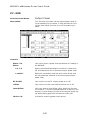
The following procedure describes how to access LabWindows and load files.
Move to the directory containing the LabWindows executable (*.EXE)
files. (This directory is usually named \LW.)
Type LW.
This places you in the PROGRAM window of the LabWindows
environment (below).
2-3
680XXB LabWindows Drivers User’s Guide
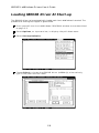
Loading 680XXB Driver As Instrument
Module
The following procedure describes how to load the 680XXB Driver as an instrument
module.
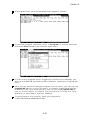
Select Instruments, on the top menu bar (below), to display the pulldown menu.
Select Load, then change to the \LW\INSTR subdirectory (below).
Move the cursor to w680b.fp and select Load.
2-4
Section 2
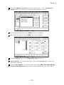
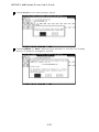
Move the cursor to Instruments to display the pull-down menu. The “ANRITSU 680XXB Synthesized CW Generator” title displays showing that
the instrument module is now loaded.
Select ANRITSU 680XXB Synthesized CW Generator, and observe
that the 680XXB main panel appears (below).
You are now ready to proceed with developing control code using the
680XXB instrument driver.
2-5
680XXB LabWindows Drivers User’s Guide
Loading 680XXB Driver At Start-up
The 680XXB driver can be automatically loaded each time LabWindows is started. The
procedure for making this happen is given below.
Place yourself into the LabWindows PROGRAM window as was described
on page 2-3.
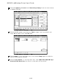
Select Options, on top menu bar, to display the pull-down menu.
Select Startup Defaults.
Choose Select to locate the 680XXB driver (w680b.fp); alternatively,
type in the path and file name.
2-6
Section 2
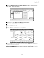
Choose the \LW\INSTR subdirectory from the file list.
Choose w680b.fp from the displayed file list, and click on Load.
The appropriate path will now be displayed in the INSTRUMENT MODULES window. Select OK to exit. The W680B driver will now be loaded
automatically each time LabWindows is entered.
2-7
680XXB LabWindows Drivers User’s Guide
Debug Utility
The 680XXB LabWindows driver incorporates a unique Debug utility, which should be
used for program development only. It should be disabled when compiling stand alone
applications.
Error 305 is returned when the instrument has generated an unexpected SRQ. To determine the cause of the SRQ set the Debug switch to On (Debug%=1), the driver will respond with a specific 3XX error code (Table 2-1).
Table 2-1.
Error Codes
Er ror Code
Descr iption
301
Parameter Range Error
302
File Not Found
310
Disk Failure
311
Self Test Failed
312
Hardware Error
2-8
Section 2
Tutorial
This tutorial takes you through the development of a simple program. This program initializes the 680XXB Synthesized CW Generator, assigns step-sweep frequencies, a
power level, and closes the driver. When you have finished stepping through the tutorial, you will have a BASIC program that can be compiled as a DOS executable (*.EXE)
file. A Microsoft C program could be produced in the exact same manner by switching
the native language to C (under the Program menu).
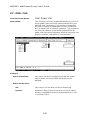
Move cursor to Instruments in the top menu bar, and select ANRITSU
680XXB Synthesized CW Generator. This will display the pull-down
menu shown below.
Choose Select to display the Initialize panel (below).
With the Source Address highlighted as shown, enter the 680XXB
GPIB address (a number between 1 and 30; 5 is the default).
2-9
680XXB LabWindows Driver User’s Guide
Select Go! (below) in the top menu bar. If a 680XXB is connected and
set to GPIB address 5, it will respond by resetting itself and returning
an identification string that will fill the Model Number, Firmware
Rev, Minimum Frequency, Maximum Frequency, Serial Number,
Minimum Output Power, and Maximum Output Power fields.
Leave Debug Flag set to Off. This switch was discussed on page 2-8.
Move the cursor to Keep!, in the top menu bar, then choose Keep from
the next window (below) to select the default option. This transfers the
code shown at the bottom of the panel to the PROGRAM window of the
LabWindows environment.
Select Instruments, in the top menu bar, then ANRITSU 680XXB Synthesized CW Generator to return to the 680XXB Driver main panel.
2-10
Section 2
Select Frequency Control, from the main menu, then Frequency
Setup when the Frequency Control menu appears (below).
Select F1 (below), and enter 2000 from the keyboard.
With F2 highlighted, enter 8400 from the keyboard.
Select Load All, from the Frequency Select control.
Select Keep!, in the top menu bar; then choose Keep again when the
next menu appears.
Select Instruments, in the top menu bar, then ANRITSU 680XXB Synthesized CW Generator to return to the 680XXB Driver main panel.
2-11
680XXB LabWindows Driver User’s Guide
Select Frequency Control and Start/Stop Sweep from the next menus
to appear (below).
Select F1–F2 sweep range (below), Auto trigger, and the default settings 10 ms dwell time, and 50 steps.
Select Keep!, in the top menu bar; then choose Keep again to add the
code to the program window.
Select Instruments, in the top menu bar, then ANRITSU 680XXB Synthesized CW Generator to return to the main driver panel.
2-12
Section 2
Select Power Control then Output Power (below) to display the output power panel (next menu).
Select L0 on the Power List Select control (below) .
Select the RF On/Off control to be On.
Select Offset to be Off.
Enter – 5 from the keyboard in the L0 field.
Select Keep!, in the top menu bar; then choose Keep again to add the
code to the program window.
Select Instruments, in the top menu bar, then ANRITSU 680XXB Synthesized CW Generator to return to the main driver panel.
2-13
680XXB LabWindows Driver User’s Guide
Move cursor to Close (below) and choose Select to display the Close
panel
There is nothing you need to do with this panel, except to select Keep!,
in the top menu bar; then choose Keep again to add the code to the program window.
Select Return! on the menu panel to return to the PROGRAM area.
2-14
Section 2
The program that you have developed now appears (below).
To test the program, move the cursor to Program, in the top menu bar
and select Run (below) from the pull-down menu.
If there are no program errors triggering a syntax error message, you
will see the 680XXB Synthesized CW Generator respond to the program
code.
After you are satisfied that the program runs correctly, you can use the
Create.EXE option, on the File menu, to create a stand-alone DOS executable (*.EXE) file. Alternatively, you can use the Create RTM option, on the file menu, to create a run-time version (*.RTM) file. That
operation is described in the next heading.
To continue with this tutorial, save this program as
\LW\PROGRAMS\W680SAMP.BAS
2-15
680XXB LabWindows Driver User’s Guide
Creating a Compiled Program
Most programs developed with LabWindows can be compiled with the Microsoft C or BASIC compiler. Some applications, however, become too large to compile and run in the
640 KB DOS memory and must be run within LabWindows or the LabWindows RunTime System. The LabWindows Run-Time System includes a DOS extender so programs
can access up to 16 MB of memory during execution. Programs executed in the run-time
system can make calls to any of the LabWindows libraries and instrument drivers. Programs distributed with the run-time system are in a binary format, so the programs
cannot be edited.
A stand-alone application (*.EXE or *.RTM) that incorporates the 680XXB Driver may
be created using the Microsoft C or BASIC compilers or LabWindows Run-Time System.
To avoid OUT OF MEMORY errors when using the Microsoft QuickBASIC compiler,
you must first optimize the 680XXB Driver memory usage with the LabWindows FUNNEL.EXE utility (See the LabWindows User’s Manual for instructions).
The LWMAKE option on the file menu can be used to create an executable file in either
BASIC or C. The following provides a step-by-step tutorial for creating a *.EXE file using the BASIC compiler. This tutorial assumes that you have read and are familiar
with the LWMAKE utility description in the LabWindows User’s Manual.
We will start with the program that you completed in the preceeding tutorial. If you
did not complete the tutorial, you can type the program listing shown on the preceeding
page, and save it as drive\LW\PROGRAMS\W680SAMP.BAS.
Move the cursor to Instruments, in the top menu bar, and ensure that
the ANRITSU 680XXB Synthesized CW Generator driver is loaded. If
it is not loaded, refer to pages 2-4 and 2-5 for instructions.
Move the cursor to File, in the top menu bar, and select Create EXE
from the pull-down menu (below).
2-16
Section 2
Choose Compile (or Check Syntax, if you have run the program before), when the next prompt appears.
Answer OK to the next prompt. This will include calls to the two required files shown in the file list. These files contain code needed to
run your application.
2-17
680XXB LabWindows Driver User’s Guide
Choose Save for the next prompt, below.
Choose Update (or Save, depending on whether or not the file already
exists), to save the changes to the file.
2-18
Section 2
Choose Run LWMAKE, in the next prompt.
Move cursor to Build and choose Make from the pull-down menu.
(Note: This assumes that the compile, link, and output paths have been
previously defined under the LWMAKE Options menu.)
At the conclusion of the processing that occurs next, the DOS executable file W680SAMP.EXE will appear in the subdirectory containing
the like-named BASIC file. Press <ENTER> to return to the LWMAKE
screen. To return to the LabWindows PROGRAM window, select QUITReturn to LabWindows from the File menu.
To check your handiwork, choose DOS SHELL from the File menu. At
the ensuing DOS prompt, type ;7%14 to run the program.
2-19/2-20
Section 3
Driver References
Section 3
Driver References
Introduction
This section lists all the 680XXB Instrument Driver function calls in alphabetical
order.
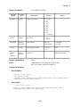
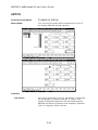
Function Panel Structure
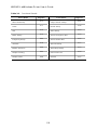
The 680XXB Labwindows Driver contains 18 panels that provide an intuitive method
for coding instrument functions. Figure 3-1 shows the hierachial structure of the functional panels. Table 3-1 lists these panels and shows the page number on which they
are described.
3-3
680XXB LabWindows Driver User’s Guide
Table 3-1.
Functional Panels
P anel Name
Alter nate Sw eep
Clos e
CW
Delta S weep
Frequency S etup
Initialize
Mark er Selection
Output Leveling
Output P ower
P anel Name
Page N o.
3- 8
Output P ower Sw eep
3- 6
Recall S etup
3-10
Save S etup
3-12
Sour ce Frequency D ef
3-34
Sour c e Pow er D ef
3-18
Special S weep
3-36
Star t/Stop S weep
3-24
User Pow er C al
3-28
Utilities
3-4
Page N o.
3-32
3-38
3-40
3-20
3-22
3-14
3-16
3-30
3-42
Section 3
SETCW
List Select
Frequency Select
F0 thru M9
FC.CW
CW Frequency
(F0 through M9)
FC.STST
Sweep Range
Trigger
Dwell Time
Number of Steps
INIT.FREQ
F0 thru M9
Returned Values
FC.DELTA
Center Frequency
Frequency Span
Trigger
Dwell Time
Number of Steps
INIT.PWR
F0 thru F9
Returned Values
Frequency Setup...
CW...
Start/Stop Sweep...
Delta Sweep...
Alternate Sweep...
Special Sweep...
Marker Selection...
FC.ALS
Alternate Sweep
Alt Sweep Power
FC.SPEC
Data Select
Array Name
Number of Elements
SETMK
List Select
Marker Selection
0 thru 9 On/Off
Output Power
Output Power Sweep
Output Leveling
User Power Calibrate
Initialize
Wiltron 680XXB
Synthesized
CW
Generator
Source Frequency Def
Source Power Def
Frequency Control. . .
Power Control. . .
SR.SAVE
Save/Recall Functions. . .
Save Register Select
Utilities
Close
Save Setup
SR.RECALL
Recall Setup
PC.PWR
Power List Select
RF On/Off
Offset
Level Offset
L0 thru L9
PC.PWRS
Sweep Type
Level 1
Level 2
Number of Steps
Dwell Time
Recall Register Select
UT
Blanking Pulse -5V/+5V
Front Panel Display On/Off
CW Ramp On/Off
RF Output (During BW) On/Off
RF Output (During Retrace) On/Off
PC.LEVEL
Leveling
ALC In
Level Correction
Ext Gain DAC
ALC Attenuation
ALC Step Attenuator
ALC Power Slope
Power Slope Pivot
Power Slope Value
PC.PWR.CAL
User Calibrations
Define Calibration
File Name
Figure 3-1.
Function Panel Tree
3-5
680XXB LabWindows Driver User’s Guide
GPSWI
Function Panel Name:
Close
Description:
This function closes the GPIB communications with the
680XXB.
Controls:
None
3-6
Section 3
Input Parameters:
None.
Output Parameters:
None.
Error:
LabWindows error codes only 220 to 240.
3XX Instrument Specific (Page 2-8)
Program Examples:
Quick BASIC:
6)1'PSWIGSQQYRMGEXMSRW[MXLXLIHVMZIV
'%00;&GPSWI
Microsoft C:
'PSWIGSQQYRMGEXMSRW[MXLXLIHVMZIV
;&CGPSWI
3-7
680XXB LabWindows Driver User’s Guide
*'%07
Function Panel Name:
Alternate Sweep
Description:
This function lets users alternate an existing sweep
with another phase-locked sweep. The source must be
sweeping prior to using this function or no action is
taken.
Controls:
Alternate Sweep:
Lets users select the sweep range that will alternate
with the primary sweep: F1–F2, F3–F4, Full, Delta F5
(∆ F5), Delta F6 (∆ F6), Delta F1 (∆ F1). The 680XXB
must have a primary sweep selected and defined before
an alternate sweep can be selected.
Alt Sweep Power:
Selects the power parameter that is to be used for the
Alt Sweep power level. The main sweep’s power level is
selected and defined in the Output Power (pc-pwr)
panel.
NOTE
The main sweep and the alternate sweep may
each have an independent power level associated
with the frequency-sweep range. If you want the
two sweeps to have different power levels, set
the alternate sweep level in this panel and the
main sweep power level in the Output Power
panel. If you do not want to have different power
levels, make the Alt Sweep Power parameter the
same as the main sweep parameter. That is, if
parameter L0 has been selected for the main
sweep, then select L0 for the Alt Sweep also.
3-8
Section 3
Input Parameters:
V ariable
Name
V ariable
Type
(D) is default setting.
Descr iption
Det ails
ALTS %
Integer
Alter nate Sw eep
1,
2,
3,
4,
5,
6,
F1–F2 ( D)
Full B and
F3–F4
D elta F1
D elta F5
D elta F6
S2L%
Integer
Alt S weep P ower
0 thr u 9 = L0 (D )
thr u L9, respectively
Output Parameters:
None.
Error:
LabWindows error codes 220 to 240
3XX Instrument Specific (Page 2-8)
Program Examples:
Quick BASIC:
6)17IPIGXWW[IITXSEPXIVREXI[MXLQEMRW[IIT
'%00;&*'%07%08770
Microsoft C:
7IPIGXWW[IITXSEPXIVREXI[MXLQEMRW[IIT
;&C*'C%07%08770
3-9
R ange
N/A
Model
dependent
680XXB LabWindows Driver User’s Guide
*'';
Function Panel Name:
CW
Description:
This function lets users select the desired CW output
frequency from the values already stored in the
680XXB frequency registers.
Controls:
List Select:
Lets users select the F0–F9 frequency set or the M0–
M9 frequency set.
CW Frequency:
Lets users select CW output frequency from one of the
twenty user-defined frequency registers: F0 through F9
or M0 through M9 (see WIXG[ function, page 3-34).
Frequency Selected:
Returns the CW frequency currently stored in the
selected register, in MHz.
3-10
Section 3
Input Parameters:
Var iable Name
V ariable
Type
LS%
Integer
List Select
1 = F(fr eq)
2 = M(fr eq)
FRE QS EL%
Integer
The frequency of oper ation
1–9
Descr iption
D etails
Output Parameters:
Var iable Name
FSE L#
V ariable
Type
D ouble
P recision
Error:
Descr iption
D etails
Frequency r eturned fr om
680XX B.
LabWindows error codes only 220 to 240
3XX Instrument Specific (Page 2-8)
Program Examples:
Quick BASIC:
6)17IPIGXE';JVIUYIRG]ERHZEPYI
'%00;&*'';07*6)57)0*7)0
Microsoft C:
7IPIGXE';JVIUYIRG]ERHZEPYI
;&C*'C';07*6)57)0*7)0
3-11
680XXB LabWindows Driver User’s Guide
*'()08%
Function Panel Name:
Delta Sweep
Description:
This function lets users set a center frequency, sweep
trigger, and span for the sweep range.
Controls:
Center Frequency:
Lets users select the center frequency F0, F1, F5, or F6
for a delta sweep.
Frequency Span:
Lets users select a sweep width (span) in MHz. The
680XXB will sweep upwards in frequency from
Center – (span/2) to Center + (span/2).
Trigger:
Lets users select the triggering source for the delta
sweep:
Auto:
Sweep is triggered automatically.
Ext/Single:
Sweep can be triggered manually by supplying a TTL
pulse to pin 13 of the rear panel AUX I/O connector. The
ability to launch a single sweep internally is currently
inoperative.
Dwell Time:
Lets users enter the dwell time for a phase-locked
sweep.
Number of Steps:
Lets users enter the number of frequency steps for a
phase-locked sweep.
3-12
Section 3
Input Parameters:
V ariable
Name
V ariable
Type
(D) is default setting.
Descr iption
D etails
F0
F1 ( D)
F5
F6
Range
CFR EQ%
Integer
Center Frequency
0,
1,
5,
6,
FSP AN #
D ouble
P recision
Frequency
Span( MHz)
1000 MH z (D )
1 kH z to full
r ange of
680X XB .
TRIGG%
Integer
Trigger Conditions
0, A uto (D )
1, E xt/Single
( Cur rently
inoper ative)
N /A
DTIME #
D ouble
P recision
PhaseLocked
Dw ell Time
10 mS ec (D )
1 ms to 99 s.
NU MST%
Integer
Number of Steps
For P hase Locked
Sw eeps
50 ( D)
1 to 10,000
steps
N /A
Output Parameters:
None.
Error:
LabWindows error codes only 220 to 240
3XX Instrument Specific (Page 2-8)
Program Examples:
Quick BASIC:
6)17IPIGXWHIPXEW[IIT
'%00;&*'()08%'6)5*74%286-++(8-1)29178
Microsoft C:
7IPIGXWHIPXEW[IIT
;&C*'C()08%'6)5*74%286-++(8-1)29178
3-13
680XXB LabWindows Driver User’s Guide
*'74)'
Function Panel Name:
Special Sweep
Description:
This function lets users specify frequencies and the order that the frequency will be output. The operator can
specify up to 1000 discrete frequencies.
Controls:
Data Select:
Lets users select between new and existing *.wsw (disk
file) data.
Array Name:
Lets users enter the name of the data-array holding the
new or existing data. If no array name is entered, the
special sweep will still be generated. However, it will
not be stored to disk in the current default directory.
Number of
Elements:
Enter the number of frequencies for a user-defined special sweep. The number of steps = (the number of frequencies –1).
3-14
Section 3
Input Parameters:
Same as controls.
Var iable Name
V ariable
Type
DS EL%
Integer
Data select
0 = N ew data file
1 = E xisting data file
DP TS%
Integer
Number of Elements
N umber of fr equencies to be
enter ed or r ecalled.
TES T$
S tring
File Name
If no file name is enter ed the
special sw eep is still generated but
not saved. The dr iver automatically
appends a “ .wsw ” extension to the
user -enter ed filename. The file is
saved to the cur rent default
dir ectory.
Descr iption
Det ails
Output Parameters:
None.
Error:
LabWindows error codes only 220 to 240. If debug
3XX Instrument Specific (Page 2-8)
Program Examples:
Quick BASIC:
6)10IXWSTIVEXSVIRXIVJVIUYIRGMIWMR+MKELIVX^JSVEYWIVHI
JMRIHWTIGMEPW[IIT
'%00;&*'74)'(7)0(4878)78
Microsoft C:
0IXWSTIVEXSVIRXIVJVIUYIRGMIWMR+MKELIVX^JSVEYWIVHI
JMRIHWTIGMEPW[IIT
;&C*'C74)'(7)0(4878)78
3-15
680XXB LabWindows Driver User’s Guide
*'7878
Function Panel Name:
Start/Stop Sweep
Description:
This function lets users select the 680XXB sweep
range. The function uses the existing definitions for
CW frequencies. The user has the opportunity to select
the source trigger conditions and set the phase-locked
step-sweep dwell time.
Controls:
Sweep Range:
Trigger:
Lets users select the primary sweep range: F1–F2,
F3–F4, or Full band.
Lets users select the triggering source for the primary
sweep:
Auto:
Sweep is triggered automatically by the 680XXB.
Ext/Single:
Sweep can be triggered manually by supplying a TTL
pulse to pin 13 of the rear panel AUX I/O connector. The
ability to launch a single sweep internally is currently
inoperative.
Dwell Time:
Lets users enter the dwell time between adjacent frequency steps for a phase-locked sweep.
Number of Steps:
Lets users enter the number of frequency steps for a
phase-locked sweep.
3-16
Section 3
Input Parameters:
V ariable
N ame
V ariable
Type
(D) is default setting.
D escript ion
D etails
R ange
SWR AN GE %
Integer
Sw eep Range
1,F1–F2
2, Full Range ( D)
3, F3–F4
N/A
TRIGG%
Integer
Trigger Conditions
0, Auto ( D)
1, Ext/S ingle
(C urr ently
inoperative)
N/A
DTIME #
Double
Pr ecision
PhaseLocked D well Time
10 mSec ( D)
1 ms to 99 s.
NU MST%
Integer
Number of Steps For
Phase Locked S weeps
50 (D )
1 to 10,000
steps.
Output Parameters:
None.
Error:
LabWindows error codes only 220 to 240
3XX Instrument Specific (Page 2-8)
Program Examples:
Quick BASIC:
6)17IPIGXWETVMQEV]QEMRW[IIT
'%00;&*'78787;6%2+)86-++(8-1)29178
Microsoft C:
7IPIGXWETVMQEV]QEMRW[IIT
;&C*'C78787;6%2+)86-++(8-1)29178
3-17
680XXB LabWindows Driver User’s Guide
-2-8
Function Panel Name:
Initialize
Description:
This function opens the GPIB communication with the
680XXB and sets it to its preset state. The device configuration must already be completed.
Controls:
Source Address:
Lets users enter a GPIB address for the 680XXB. The
factory-set default address is 5.
Model Number:
Displays the returned 680XXB model number.
Firmware Rev:
Displays the returned firmware revision level.
Minimum Frequency:
Displays the returned minimum frequency for a full
band sweep.
Maximum Frequency:
Displays the returned maximum frequency for a full
band sweep.
Serial Number:
Displays the returned 680XXB serial number.
Minimum Output
Power:
Displays the returned minimum output power to which
the 680XXB can be set.
Maximum Output
Power:
Displays the returned maximum output power to which
the 680XXB can be set.
Driver Rev.:
Displays the driver’s revision level.
Debug Flag:
Lets users turn the Debug Utility on or off. This utility
is discussed on page 2-8.
3-18
Section 3
Input Parameters:
V ariable
N ame
AD D%
Var iable
Type
Integer
Same as controls.
D escript ion
GPIB Addr ess
D etails
R ange
1–9, 5 (D )
1 to 31
Output Parameters:
V ariable
N ame
Var iable
Type
Descr iption
LOWF$
Str ing
R eturned minimum fr equency
HIGH$
Str ing
R eturned maximum fr equency
MOD EL$
Str ing
R eturned model number
SWR V$
Str ing
R eturned softw are r evision number
MINP WR$
Str ing
R eturned minimum pow er level
GP WR$
Str ing
R eturned guar anteed power level
SS N$
Str ing
R eturned instr ument serial number
Error:
D etails
680XX B OI string is
parsed to supply values
for the str ing variables
shown in this table
LabWindows error codes only 220 to 240
3XX Instrument Specific (Page 2-8)
Program Examples:
Quick BASIC:
6)1-RMXMEPM^IWXLI<<&
'%00;&-2-8%((
Microsoft C:
-RMXMEPM^IWXLI<<&
;&C-2-8%((
3-19
680XXB LabWindows Driver User’s Guide
-2-8*6)5
Function Panel Name:
Source Frequency Def(inition)
Description:
This function returns the values of the frequencies (F0–
F9, M0–M9) that are presently stored in the 680XXB
storage registers. All frequencies are returned in megahertz. There are no operator inputs.
Controls:
F0 – F9:
Displays the returned 680XXB F0–F9 frequency.
M0 – M9:
Displays the returned 680XXB M0–M9 frequency.
(Press the <Down Page> key to access this panel.)
3-20
Section 3
Input Parameters:
None.
Output Parameters:
V ariable
Name
Var iable
Type
Descr iption
F0# thru F9#
D ouble
P recision
C W frequencies active in the stor age register s.
M0# thru M9#
D ouble
P recision
C W frequencies active in the stor age register s.
Error:
LabWindows error codes only 220 to 240
3XX Instrument Specific (Page 2-8)
Program Examples:
Quick BASIC:
6)1+IXXLIZEPYIJSVYTXSX[IRX]JVIUYIRGMIW
;&-2-8*6)5**********
1111111111
Microsoft C:
+IXXLIZEPYIJSVYTXSRMRIJVIUYIRGMIW
;&C-2-8C*6)5**********
1111111111
3-21
680XXB LabWindows Driver User’s Guide
-2-84;6
Function Panel Name:
Source Power Def(inition)
Description:
This function returns the values of power levels L0–L9
that are presently stored in the 680XXB storage registers. All frequencies are returned in dBm. There are no
operator inputs.
Controls:
L0 – L9:
Displays the returned 680XXBL0–L9 power levels.
3-22
Section 3
Input Parameters:
None.
Output Parameters:
V ariable
Name
F0# thru F9#
Var iable
Type
D ouble
P recision
Error:
Descr iption
P ower levels active in the storage r egisters.
LabWindows error codes only 220 to 240
3XX Instrument Specific (Page 2-8)
Program Examples:
Quick BASIC:
6)1+IXXLIZEPYIJSVYTXSX[IRX]JVIUYIRGMIW
;&-2-8*6)50000000000
Microsoft C:
+IXXLIZEPYIJSVYTXSRMRIJVIUYIRGMIW
;&C-2-8C*6)50000000000
3-23
680XXB LabWindows Driver User’s Guide
4'0):)0
Function Panel Name:
Output Leveling
Description:
This function lets users select the power leveling
mode(s).
Controls:
Leveling
Lets users select the leveling mode for the output
power.
Fixed Gain:
ALC is disabled. The RF Level DAC and step attenuator (if installed) control the relative power level.
Power is not detected at any point, and the absolute
power level is uncalibrated.
Internal:
Output power is leveled using an internal detector in
the directional coupler to sample the output signal.
External Det:
Output power is leveled using an external detector to
sample the output signal.
Ext Pwr Mtr:
Output power is leveled by using the “recorder voltage”
from an external power meter. The 680XXB is compatible with power meters having a ±1 V full scale analog
output.
ALC Input:
Lets users select the front or rear panel ALC Input connector
Level Correction:
Turns the leveling correction from the external detector
or power meter on or off.
Ext Gain DAC:
Allows adjustment of the external-level-gain DAC to optimize loop stability. Enter a value between 0 and 255.
3-24
Section 3
ALC
Attenuation:
Couples or decouples the step attenuator from the ALC
loop.
ALC Step
Attenuator:
Pressing the right arrow turns the optional step attenuator on and increases it in 10 dB steps to 110 dB (decoupled mode only).
ALC Power Slope:
Lets users turn ALC power slope on or off. Power slope
compensates for system, cable, and waveguide varations due to changes in frequency.
Power Slope Pivot:
Lets user enter a model-dependent frequency value for
the power slope pivot point. Pivot point can be any frequency within the range of the instrument.
Power Slope Value:
Lets user enter a value for the ALC slope DAC of between 0 and 255
3-25
680XXB LabWindows Driver User’s Guide
Input Parameters:
V ariable
N ame
Var iable
Type
(D) is default setting
D escript ion
D etails
R ange
LEV %
Integer
Leveling
0,
1,
2,
3,
Fixed Gain
Internal ( D)
Ext D et
Ext P wr Mtr
N /A
ALC CP %
Integer
A LC A ttenuation
0, Coupled ( D)
1, Decouple
N /A
LVC %
Integer
Level C orr ection
0, Off ( D)
1, On
N /A
EX DA C#
Double
Pr ecision
E x t Gain D AC
0 (D )
0 to 255
ALC IN%
Integer
A LC In
0, Front ( D)
1, Rear
N /A
ATT$
Str ing
A LC S tep Attenuator
“00"
”01"
“02"
”03"
“04"
”05"
“06"
”07"
“08"
”09"
“10"
”11"
N /A
ALC PS %
Integer
A LC P ower Slope
0, Off ( D)
1, On
N /A
PV T#
Double
Pr ecision
P ower Slope P ivot
Default, 2 GHz
Model
D ependent
VL%
Integer
P ower Slope V alue
Default, 128
1 to 255
3-26
=
=
=
=
=
=
=
=
=
=
=
=
O ff (D )
10 dB
20 dB
30 dB
40 dB
50 dB
60 dB
70 dB
80 dB
90 dB
100 dB
110 dB
Section 3
Output Parameters:
None.
Error:
LabWindows error codes only 220 to 240
3XX Instrument Specific (Page 2-8)
Program Examples:
Quick BASIC:
6)17IPIGXXLIPIZIPMRKQSHI
'%00;&4'0):)00):%0''40:')<(%'
%0'-2%88%0'474:8:0
Microsoft C:
7IPIGXXLIPIZIPMRKQSHI
;&C4'C0):)00):%0''40:')<(%'%0'-2%88%0'474:8:0
3-27
680XXB LabWindows Driver User’s Guide
4'4;6
Function Panel Name:
Output Power
Description:
This function lets users set the output power level using an editable list of values. It also provides for turning the level offset function on or off and setting its
value.
Controls:
Power List
Select:
Lets users select a power level parameter for loading in
the 680XXB.
L0 – L9:
Opens the selected parameter and lets its value to be
set and selected as the instrument output power level.
Load All:
Opens all parameters and lets their value be set and
the L9 parameter selected as the instrument output
power level.
RF On/Off:
Offset:
Lets users turn the RF output power on or off.
Lets users turn the Level Offset function on or off.
Level Offset:
Lets user enter a level offset value, when the function
is turned on. This value compensates for a device in the
output line that alters the level of the output power signal before being applied to the device-under-test.
L0 thru L9:
Provide for entering power level values.
3-28
Section 3
Input Parameters:
Var iable
Name
Var iable
Type
(D) is default setting.
Descr iption
Det ails
R ange
PWR SE L%
Integer
P ower List Select
0 = L0 ( D)
1 = L1
2 = L2
3 = L3
4 = L4
5 = L5
6 = L6
7 = L7
8 = L8
9 = L9
10 = Load A ll
OTP %
Integer
R F On/Off
0 = Off
1 = On (D )
LEV OFF#
Double
Pr ecision
Level Offset
V alue of
P ower Offset
+100 dB to
–100 dB
LVLP %
Integer
Level Offset On/Off
0, Off (D )
1, On
N /A
PWR 0#
thru
PWR 9#
Double
Pr ecision
L0 thr u L9
Model dependent.
Output Parameters:
None.
Error:
LabWindows error codes only 220 to 240
3XX Instrument Specific (Page 2-8)
Program Examples:
Quick BASIC:
6)17IXSYXTYXTS[IV
'%00;&4'4;6
4;67)03840):3**0:044;64;64;64;64;64;6
4;64;64;64;64;6
Microsoft C:
7IXSYXTYXTS[IV
;&C4'C4;64;67)03840):3**0:044;64;64;64;6
4;64;64;64;64;64;64;6
3-29
680XXB LabWindows Driver User’s Guide
4'4;6'%0
Function Panel Name:
User Power Cal
Description:
This function lets users enable and disable up to five internal power level correction tables created using the
680XXB User Cal feature. This function also permits
the user to upload and download the user cal data for
all five table from an external computer. The purpose of
the User Cal feature is to provide compensation for
power level variations caused by external switching, amplifiers, couplers, and cables in the test setup.
Controls:
User Calibrations:
Lets users activate a numbered, pre-defined, power
level-flatness-correction table stored within the
680XXB.
Define Calibration:
Off:
Lets users turn the level-correction feature off.
Upload:
Uploads to disk all five of the level-correction tables
stored in the 680XXB to the filename specified in the
“File Name” field.
3-30
Section 3
Download:
Downloads data from the disk “File Name” file to the
680XXB that fills all five memory “User x” locations in
the 680XXB.
CAUTION
Downloading data from the disk overwrites
any data that was previously stored in these
User x memory locatgions.
Input Parameters:
Var iable
Name
Var iable
Type
(D) is default setting.
D escript ion
D etails
UC AL%
Integer
U s er C alibration
0
1
2
2
4
5
=Off ( D)
= User 1
= User 2
= User 3
= User 4
= User 5
DC AL%
Integer
D efine Cal
1 = Off( D)
2 = Upload
3 = Dow nload
FAME $
Str ing
File Name
8 character s maximum
Output Parameters:
None.
Error:
LabWindows error codes only 220 to 240
3XX Instrument Specific (Page 2-8)
Program Examples:
Quick BASIC:
6)17IXYWIVGEPJIEXYVITS[IV
'%00;&4'4;6'%09'%0('%0*%1)
Microsoft C:
7IXYWIVGEPJIEXYVITS[IV
;&C4'C4;6C'%09'%0('%0*%1)
3-31
680XXB LabWindows Driver User’s Guide
4'4;67
Function Panel Name:
Output Power Sweep
Description:
This function lets users set up the power sweep mode of
operation.
Controls:
Level 1 :
Lets users enter the setting in dBm for the start power
level value. This is the start value for the power sweep.
Level 2 :
Lets users enter the setting in dBm for the stop power
level value. This is the stop value for the power sweep.
NOTE
Power sweep can be from high to low or low to
high power levels. Therefore, the Level 1
(start) power could be higher or lower than the
Level 2 (stop) power.
Number of Steps:
Lets users enter the number of discrete power points
(steps) at which the sweep will pause (as set using
Dwell Time control).
Dwell Time:
Lets users enter the length of time they want the power
sweep to remain (dwell) at each step.
3-32
Section 3
Input Parameters:
Var iable
N ame
V ariable
Type
(D) is default setting.
D escript ion
Det ails
R ange
LVL1#
R eal
Level 1 Output
Pow er
0 dB m (D )
Model D ependent
LVL2#
R eal
Level 2 Output
Pow er
0 dB m (D )
S ame as above.
NU MST%
Integer
Number of Steps
from Level 1 to Level
2
50 steps ( D)
0.01 to full pow er of
instr ument, which is
model dependent.
DWT#
R eal
Dw ell Time At E ach
Step
50 ms ( D)
1 ms to 99 s.
Output Parameters:
None.
Error:
LabWindows error codes only 220 to 240
3XX Instrument Specific (Page 2-8)
Program Examples:
Quick BASIC:
6)1(IJMRIXLITS[IVW[IIT
'%00;&4'4;674780:00:029178(;80:070:07
Microsoft C:
(IJMRIXLITS[IVW[IIT
;&C4'C4;674780:00:029178(;80:070:07
3-33
680XXB LabWindows Driver User’s Guide
7)8';
Function Panel Name:
Frequency Setup
Description:
This function lets users define frequencies for any of
the twenty 680XXB storage registers.
Controls:
List Select:
Lets users select the F0-F9 set, M0-M9 set, or both sets
for assignment of frequency values. If “Both” is selected, all defined frequencies will be loaded and the
680XXB will be set to output the M-frequency selection
(0–9 on Frequency Select control).
3-34
Section 3
Frequency Select:
Lets users select any single frequency storage location,
or to select all twenty at one time. If more than one frequency is to be defined, the switch must be set to the
Load All position. Press the <Page Down> key to call up
page 2 and the Mx set for assigning frequency definitions
F0 thru F9
M0 thru M9:
Let users enter a frequency value in MHz for storage in
the applicable location (register).
Input Parameters:
Var iable Name
V ariable
Type
FRE QS EL%
Integer
Selects Fr equencies 1–20, wher e 20 loads all frequencies.If
any other value, it selectively loads that value into the
corr esponding register . If a selective load is used, that
frequency then becomes the active output fr equency. If load
all is selected (10) , then frequency r egister 9 ( F9) becomes
the active output when the function is complete.
FRx#
R eal
Frequency to be loaded into the stor age register s.
MFx#
R eal
Frequency to be loaded into the stor age register s.
Descr iption
Output Parameters:
None.
Error:
LabWindows error codes only 220 to 240
3XX Instrument Specific (Page 2-8)
Program Examples:
Quick BASIC:
6)17IPIGXEG[JVIUYIRG]WXSVEKIPSGEXMSRERHPSEHJVIUYIRG]
ZEPYI
'%00;&7)8';
*6)57)0*6*6*6*6*6*6*6*6*6
*61*1*1*1*1*1*1*1*1*1*
Microsoft C:
7IPIGXEG[JVIUYIRG]WXSVEKIPSGEXMSRERHPSEHJVIUYIRG]
ZEPYI
;&C7)8';*6)57)0*6*6*6*6*6*6*6*6*6
*6*61*1*1*1*1*1*1*1*1*
3-35
680XXB LabWindows Driver User’s Guide
7)81/
Function Panel Name:
Marker Selection
Description:
This function lets users set video markers.
Controls:
List Select:
Lets users select the F0–F1 or M0–M1 frequency set.
Marker Selection:
Lets users disable markers or select Video markers.
Disable:
Disables the frequency markers.
Video:
Enables a video pulse to mark the frequency, provided
the selected marker frequency is within the selected frequency range.
0 thru 9:
Turns marker on or off at the frequency stored in
locations F0 thru F9 or M0 thru M9, based on the position of the List Select control.
3-36
Section 3
Input Parameters:
(D) is default setting.
Var iable Name
V ariable
Type
MKS EL%
Integer
Marker Select
0, D isable (D )
1, V ideo
F0% Thru
F9%
Integer
Marker :1–9
0, Off (D )
1, On
Descr iption
D etails
Output Parameters:
None.
Error:
LabWindows error codes only 220 to 240
3XX Instrument Specific (Page 2-8)
Program Examples:
Quick BASIC:
6)17IXQEVOIVW
'%00;&7)81/1/7)0**********
Microsoft C:
7IXQEVOIVW
;&C7)81/1/7)0**********
3-37
680XXB LabWindows Driver User’s Guide
766)'%00
Function Panel Name:
Recall Setup
Description:
This function lets users recall an existing source setup
from the 680XXB internal memory.
Controls:
Recall Register:
Lets users select the storage register containing the
setup they wish to recall.
3-38
Section 3
Input Parameters:
Var iable Name
V ariable
Type
RE G%
Integer
(D) is default setting.
Descr iption
Stor age Register , 1 Thru 9
D etails
1, (D )
Output Parameters:
None.
Error:
LabWindows error codes only 220 to 240
3XX Instrument Specific (Page 2-8)
Program Examples:
Quick BASIC:
6)16IGEPPWXSVIHWIXYTW
'%00;&766)'%006)+
Microsoft C:
6IGEPPWXSVIHWIXYTW
;&C76C6)'%006)+
3-39
680XXB LabWindows Driver User’s Guide
767%:)
Function Panel Name:
Save Setup
Description:
This function lets users save an existing setup to the
680XXB internal memory.
Controls:
Save Register:
Lets users select a storage register for storing a setup
they may wish to recall at a later time.
3-40
Section 3
Input Parameters:
Var iable Name
V ariable
Type
RE G%
Integer
(D) is default setting.
Descr iption
Save R egister, 1 Thr u 9
D etails
1, (D )
Output Parameters:
None.
Error:
LabWindows error codes only 220 to 240
3XX Instrument Specific (Page 2-8)
Program Examples:
Quick BASIC:
6)16IGEPPWXSVIHWIXYTW
'%00;&767%:)6)+
Microsoft C:
6IGEPPWXSVIHWIXYTW
;&C767%:)6)+
3-41
680XXB LabWindows Driver User’s Guide
98
Function Panel Name:
Utilities
Description:
This function lets users define many additional functions typically used for advanced applications. It also
controls the 680XXB during frequency switching and retrace.
Controls:
Blanking Pulse:
Lets users select rear panel AUX I/O supplied blanking
pulse to be ±5 volts during sweep retrace. (AUX I/O connection, pin 6 only).
Front Panel Disp:
Lets users turn the front panel displays on or off.
CW Ramp:
Lets users turn the CW Ramp function on or off. This
function causes a 0–10 volt horizontal ramp to be supplied to the rear panel HORIZONTAL OUTPUT connector
during CW and step sweep operations.
RF Output –
During Frequency
Switching:
Lets users turn the RF output on or off during bandswitching.
RF Output –
During Retrace:
Lets users turn the RF output on or off during sweep retracing.
3-42
Section 3
Input Parameters:
(D) is default setting.
Var iable Name
V ariable
Type
BLN KP %
Integer
Blanking P ulse
0, –5 Volt
1, +5 Volt ( D)
RFFS %
Integer
RF D uring B andswitching
0, Off
1, On ( D)
RFD R%
Integer
RF D uring R etrace
0, Off ( D)
1, 0n
FPD %
Integer
Front P anel Display
0, Off
1, On ( D)
CWR %
Integer
Rear Panel C W Ramp Out
0, Off ( D)
1, On
Descr iption
D etails
Output Parameters:
None.
Error:
LabWindows error codes only 220 to 240
3XX Instrument Specific (Page 2-8)
Program Examples:
Quick BASIC:
6)17IXFPEROMRK';VEQT6*SYXTYXHYVMRKJVIUW[MXGLMRKERH
VIXVEGITIRPMJXVIPE]JVSRXTERIPHMWTPE]ERHLMVIWSPYXMSR
ZEPYIW
'%00;&98&02/46**76*(6*4(';6
Microsoft C:
7IXFPEROMRK';VEQT6*SYXTYXHYVMRKJVIUW[MXGLMRKERH
VIXVEGITIRPMJXVIPE]JVSRXTERIPHMWTPE]ERHLMVIWSPYXMSR
ZEPYIW
;&C98&02/46**76*(6*4(';6
3-43/3-44