1
xx
ZZZ
H500 Spectrum Analyzer &
SA2500 Spectrum Analyzer
Programmer Manual
*P077078400*
077-0784-00
xx
ZZZ
H500 Spectrum Analyzer &
SA2500 Spectrum Analyzer
Programmer Manual
Revision A
www.tektronix.com
077-0784-00
Copyright © Tektronix. All rights reserved. Licensed software products are owned by Tektronix or its subsidiaries
or suppliers, and are protected by national copyright laws and international treaty provisions.
Tektronix products are covered by U.S. and foreign patents, issued and pending. Information in this publication
supersedes that in all previously published material. Specifications and price change privileges reserved.
TEKTRONIX and TEK are registered trademarks of Tektronix, Inc.
Contacting Tektronix
Tektronix, Inc.
14150 SW Karl Braun Drive
P.O. Box 500
Beaverton, OR 97077
USA
For product information, sales, service, and technical support:
In North America, call 1-800-833-9200.
Worldwide, visit www.tektronix.com to find contacts in your area.
Table of Contents
Preface ..............................................................................................................
Related Documentation ......................................................................................
iii
iii
Getting Started
Getting Started ....................................................................................................
Overview of the Manual ....................................................................................
Configuring the Network Interface ........................................................................
Using the Programmable Interface.........................................................................
1-1
1-1
1-3
1-4
Syntax and Commands
Command Syntax.................................................................................................
Backus-Naur Form Definition ..............................................................................
SCPI Commands and Queries ..............................................................................
IEEE 488.2 Common Commands..........................................................................
Constructed Mnemonics ....................................................................................
Command Groups ................................................................................................
Functional Groups ...........................................................................................
Programming Hints ........................................................................................
IEEE Common Commands....................................................................................
Abort Commands ...............................................................................................
Calculate Commands...........................................................................................
Marker Mnemonics ........................................................................................
Calibration Commands.........................................................................................
Display Commands.............................................................................................
Fetch Commands ...............................................................................................
Format Commands .............................................................................................
Initiate Commands .............................................................................................
Input Commands................................................................................................
Mass Memory Commands.....................................................................................
Output Commands..............................................................................................
Sense Commands ...............................................................................................
Status Commands...............................................................................................
System Commands .............................................................................................
Trace Commands ...............................................................................................
Trace Mnemonics ..........................................................................................
H500 & SA2500 Programmer Manual
2-1
2-1
2-2
2-7
2-7
2-8
2-9
2-10
2-11
2-12
2-13
2-15
2-16
2-17
2-18
2-19
2-20
2-21
2-22
2-23
2-24
2-25
2-26
2-27
2-28
i
Table of Contents
Trigger Commands .............................................................................................
Unit Commands.................................................................................................
Command Descriptions ........................................................................................
2-29
2-30
2-31
Status and Events
Status and Events ................................................................................................. 3-1
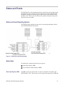
Status and Event Reporting System ....................................................................... 3-1
Status Byte.................................................................................................... 3-1
Standard Event Status Block ............................................................................... 3-4
Queues ........................................................................................................ 3-5
Status and Event Processing Sequence .................................................................... 3-6
Synchronizing Execution ................................................................................... 3-7
Error Messages and Codes....................................................................................... 3-8
Command Errors............................................................................................. 3-8
Execution Errors ............................................................................................. 3-9
Device Specific Errors .................................................................................... 3-11
Query Errors................................................................................................ 3-11
Status Conditions ............................................................................................... 3-12
Appendices
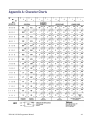
Appendix A: Character Charts .................................................................................
Appendix B: SCPI Conformance Information ...............................................................
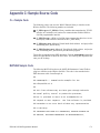
Appendix C: Sample Source Code ............................................................................
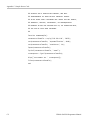
C++ Sample Code ..........................................................................................
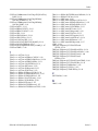
MATLAB Sample Code....................................................................................
ii
A-1
B-1
C-1
C-1
C-1
H500 & SA2500 Programmer Manual
Preface
This programmer manual covers the H500 and SA2500 Spectrum Analyzer
instruments. It provides information on operating your instrument using an
Ethernet network interface.
This manual is composed of the following sections
Getting Started outlines how to configure and use the network interface.
Syntax and Commands defines the syntax used in command descriptions,
presents a list of all command subsystems, and presents detailed descriptions
of all programming commands.
Status and Events describes how the status and Events Reporting system
operates and presents a list of all system errors.
Appendices provides additional information.
Related Documentation
H500 User Manual (Tektronix part number 071-3115-XX) and SA2500 User
Manual (Tektronix part number 071-3118-XX). These manuals contain
general information about how to put your instrument into service, guides to
user interface controls, and application examples.
H500 and SA2500 instruments Online Help The online help contains detailed
information about application controls and parameter fields.
H500 & SA2500 Programmer Manual
iii
Preface
iv
H500 & SA2500 Programmer Manual
Getting Started
Getting Started
You can write computer programs that remotely set the instrument front panel
controls or that take measurements and read those measurements for further
analysis or storage. To help you get started with programming the instrument, this
section includes the following subsections
Overview of the Manual
Summarizes each major section of this manual.
Configuring the Network Interface
Describes how to configure the H500 or SA2500 network interface, and how
to physically connect the instrument to a controller.
Using the Programmable Interface
Describes the communication protocol for using the programmable interface.
Overview of the Manual
The information contained in each major section of this manual is described below.
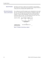
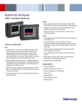
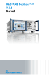
Syntax and Commands
Syntax and Commands, describes the structure and content of the messages your
program sends to the instrument. The following figure shows command parts as
described in the Command Syntax subsection.
Figure 1-1: Command parts
H500 & SA2500 Programmer Manual
1-1
Getting Started
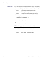
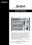
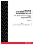
Section 2 also describes the effect of each command and provides examples
of how you might use it. The Command Groups subsection provides lists by
functional areas. The commands are listed alphabetically in the Command
Descriptions section.
Figure 1-2: Functional groupings and an alphabetical list of commands
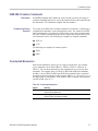
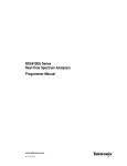
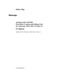
Status and Events
The program may request information from the instrument. The instrument
provides information in the form of status and error messages. The following
figure illustrates the basic operation of this system. Section 3, Status and Events,
describes how to get status or event information from the program and details
the event and error messages.
Figure 1-3: Event-driven program
1-2
H500 & SA2500 Programmer Manual
Getting Started
Configuring the Network Interface
The H500 or SA2500 programmable interface is accessible through the
instruments network interface when the H500 or SA2500 application is running.
You must configure instrument network settings before using the programmable
interface. Use the following steps to configure the instrument network interface:
1. Work with your network administrator to determine the IP address of the
H500 instrument. If the network has DHCP enabled, the instrument will
automatically obtain an IP address when powered on and connected to the
network. If your network does not support DHCP, or you need a fixed IP
address for your instrument, have your system administrator provide you
with an address.
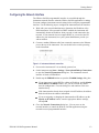
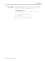
2. Connect a standard Ethernet cable from a network connector to the Ethernet
port on the top of the instrument. You can do this before or after powering
on the instrument.
Figure 1-4: Instrument ethernet connection
3. Power on the instrument if it is not already powered on.
4. On the instrument, tap Start > Settings > Network and Dial-up Connections
to open the Network Connections dialog box. The instrument network
interface is listed as ENDS4ISA1.
5. Double-tap the ENDS4ISA1 icon to open the CSA8900 Settings dialog box:
If your instrument is using DHCP to obtain an IP address, and the Obtain
an IP address via DHCP button is set, you do not need any further
network configuration. Close the dialog box and continue to the next
numbered step.
If the instrument has already been assigned a fixed IP address, the address
fields should show the address information.
If you are assigning or changing the instrument fixed IP address, tap the
Specify an IP address button, enter the appropriate address settings,
and tap OK.
6. Close the Network Connections dialog box. You can now use the
network interface to control the H500 or SA2500 application using the
network-accessed programmable interface.
H500 & SA2500 Programmer Manual
1-3
Getting Started
Using the Programmable Interface
The H500 and SA2500 programmable interface consists of simple text commands.
These are modeled after the Standard Commands for Programmable Instruments
(SCPI) syntax. As an example of a typical command, :SENS:FREQ:CENT?
requests the spectrum analyzer's center frequency. The instrument uses raw
TCP sockets to receive commands and send replies. To send a command to the
H500 or SA2500, make a connection on TCP port 34835 and send the text of the
command, followed by a newline (ASCII 10). The instrument will reply on the
same TCP port, and will add a newline to the end of its response.
Appendix C lists C++ source code that uses the Win32 Winsock library to
interface to the H500 or SA2500. Included is a custom library module with
routines for opening and closing the interface, writing commands, reading query
responses, and determining details when error conditions occur. Also included is
a test wrapper that uses the custom library module to perform basic instrument
operations. Appendix C also lists MATLAB code that uses the MATLAB
Instrument Control Toolbox plug-in to interface to the H500 or SA2500. The
MATLAB example opens the interface, sends a simple query command, and then
reads the response. The example files are provided as attachments to this PDF file.
1-4
H500 & SA2500 Programmer Manual
Syntax and Commands
Command Syntax
This section contains information on the Standard Commands for Programmable
Instruments (SCPI) and IEEE 488.2 Common Commands you can use to program
your H500 or SA2500 instrument. The information is organized in the following
subsections
Backus-Naur Form Definition
SCPI Commands and Queries
IEEE 488.2 Common Commands
Constructed Mnemonics
Backus-Naur Form Definition
This manual may describe commands and queries using the Backus-Naur Form
(BNF) notation. The following table defines the standard BNF symbols.
Table 2-1: BNF symbols and meanings
Symbol
< >
Meaning
:=
Is defined as
|
Exclusive OR
{ }
Group; one element is required
[ ]
.. .
Optional; can be omitted
( )
Comment
H500 & SA2500 Programmer Manual
Defined element
Previous element(s) may be repeated
2-1
Command Syntax
SCPI Commands and Queries
SCPI is a standard created by a consortium that provides guidelines for remote
programming of instruments. These guidelines provide a consistent programming
environment for instrument control and data transfer. This environment uses
defined programming messages, instrument responses, and data format across all
SCPI instruments, regardless of manufacturer. The instrument uses a command
language based on the SCPI standard.
The SCPI language is based on a hierarchical or tree structure as shown in the
following figure that represents a subsystem. The top level of the tree is the root
node; it is followed by one or more lower-level nodes.
Figure 2-1: Example of SCPI subsystem hierarchy tree
You can create commands and queries from these subsystem hierarchy trees.
Commands specify actions for the instrument to perform. Queries return
measurement data and information about parameter settings.
Creating Commands
SCPI commands are created by stringing together the nodes of a subsystem
hierarchy and separating each node by a colon.
In the figure above, TRIGger is the root node and EVENt, EXTernal, INPut,
INTernal, and SOURce are lower-level nodes. To create a SCPI command, start
with the root node TRIGger and move down the tree structure adding nodes
until you reach the end of a branch. Most commands and some queries have
parameters; you must include a value for these parameters. If you specify a
parameter value that is out of range, the parameter will be set to a default value.
The command descriptions list the valid values for all parameters.
For example, :TRIGger:EVENt:INTernal BOTH is a valid SCPI command created
from the hierarchy tree. (See Figure 2-1.)
Creating Queries
2-2
To create a query, start at the root node of a tree structure, move down to the end
of a branch, and add a question mark. TRIGger:EVENt:SOURce? is an example
of a valid SCPI query using the hierarchy tree in the figure. (See Figure 2-1.)
H500 & SA2500 Programmer Manual
Command Syntax
Query Responses
The query causes the instrument to return information about its status or settings.
When a query is sent to the instrument, only the values are returned. When the
returned value is a mnemonic, it is noted in abbreviated format, as shown in the
following table.
Table 2-2: Query response examples
Query
Response
CALCulate:SPECtrum:MARKer:X
7.50E+9
TRACe1:DPSA:DETection
AVER
A few queries also initiate an operation action before returning information. For
example, the *CAL? query runs a calibration.
Parameter Types
Every parameter in the command and query descriptions is of a specified type.
The parameters are enclosed in brackets, such as <value>. The parameter type is
listed after the parameter and is enclosed in parentheses, for example, (boolean).
Some parameter types are defined specifically for the H500 and SA2500
instruments command set and some are defined by ANSI/IEEE 488.2-1987 as
shown in the following table.
Table 2-3: Parameter types used in syntax descriptions
Parameter type
Description
Example
A specified length of
arbitrary data
#512234xxxxx . . . where
5 indicates that the following
5 digits (12234) specify the
length of the data in bytes;
xxxxx ... indicates the data
boolean
Boolean numbers or values
ON or 1; OFF or 0
binary
Binary numbers
#B0110
octal
Octal numbers
#Q57, #Q3
hexadecimal 2
Hexadecimal numbers
(0-9, A, B, C, D, E, F)
#HAA, #H1
NR1 2 numeric
Integers
0, 1, 15, -1
NR2 2 3
Decimal numbers
1.2, 3.141516, -6.5
arbitrary
block 1
numeric
NR3 2
numeric
Floating point numbers
3.1415E-9, -16.1E5
NRf 2
numeric
Flexible decimal number that
may be type NR1, NR2 or NR3
See NR1, NR2, and NR3
examples
Alphanumeric characters (must
be within quotation marks)
"Testing 1, 2, 3"
string 4
1
2
3
4
Defined in ANSI/IEEE 488.2 as "Definite Length Arbitrary Block Response Data."
An ANSI/IEEE 488.2-1992-defined parameter type.
Some commands and queries will accept an octal or hexadecimal value even though the parameter type is
defined as NR1.
Defined in ANSI/IEEE 488.2 as "String Response Data."
H500 & SA2500 Programmer Manual
2-3
Command Syntax
Special Characters
All characters in the range of ASCII 127-255 are defined as special characters.
These characters are used in arbitrary block arguments only; using these characters
in other parts of any command yields unpredictable results.
Abbreviating Commands,
Queries, and Parameters
You can abbreviate most SCPI commands, queries, and parameters to an accepted
short form. This manual shows these short forms as a combination of upper and
lower case letters. The upper case letters indicate the accepted short form of a
command. As shown in the following figure, you can create a short form by
using only the upper case letters. The accepted short form and the long form are
equivalent and request the same action of the instrument.
Figure 2-2: Example of abbreviating a command
2-4
H500 & SA2500 Programmer Manual
Command Syntax
Chaining Commands and
Queries
You can chain several commands or queries together into a single message. To
create a chained message, first create a command or query, add a semicolon
(;), and then add more commands or queries and semicolons until the message
is complete. If the command following a semicolon is a root node, precede it
with a colon (:). The following figure illustrates a chained message consisting
of several commands and queries. The single chained message should end in a
command or query, not a semicolon. Responses to any queries in your message
are separated by semicolons.
Figure 2-3: Example of chaining commands and queries
If a command or query has the same root and lower-level nodes as the previous
command or query, you can omit these nodes. In the following figure, the second
command has the same root node (TRIGger:EVENt) as the first command, so
these nodes can be omitted.
Figure 2-4: Example of omitting root and lower-level nodes in a chained message
H500 & SA2500 Programmer Manual
2-5
Command Syntax
General Rules
Here are three general rules for using SCPI commands, queries, and parameters:
You can use single (‘ ’) or double (“ ”) quotation marks for quoted strings, but
you cannot use both types of quotation marks for the same string.
correct
"This string uses quotation marks correctly."
correct
‘This string also uses quotation marks correctly.'
incorrect
"This string does not use quotation marks correctly.'
You can use upper case, lower case, or a mixture of both cases for all
commands, queries, and parameters.
:SENSE:DPSA:COLOR:MAXIMUM 50
is the same as
:sense:dpsa:color:maximum 50
and
:SENSE:dpsa:COLOR:maximum 50
NOTE. Literal strings (quoted) are case sensitive, for example, file names.
No embedded spaces are allowed between or within nodes.
2-6
correct
:SENSE:DPSA:COLOR:MAXIMUM 50
incorrect
:SENSE: DPSA: COLOR:MAXI MUM 50
H500 & SA2500 Programmer Manual
Command Syntax
IEEE 488.2 Common Commands
Description
ANSI/IEEE Standard 488.2 defines the codes, formats, protocols, and usage of
common commands and queries used on the interface between the controller and
the instruments. The instrument complies with this standard.
Command and Query
Structure
The syntax for an IEEE 488.2 common command is an asterisk (*) followed by a
command and, optionally, a space and parameter value. The syntax for an IEEE
488.2 common query is an asterisk (*) followed by a query and a question mark.
All of the common commands and queries are listed in the last part of the Syntax
and Commands section. The following are examples of common commands:
*ESE 16
*CLS
The following are examples of common queries
*ESR
*IDN
Constructed Mnemonics
Some header mnemonics specify one of a range of mnemonics. For example,
a trace mnemonic can be either TRACe1, TRACe2, TRACe3, TRACe4, or
TRACe5. You use these mnemonics in the command just as you do any other
mnemonic. For example, there is a TRACe1:SPECtrum:FUNCtion command,
and there is also a TRACe2:SPECtrum:FUNCtion command. In the command
descriptions, this list of choices is abbreviated as TRACe<x>. The value of <x> is
the upper range of valid suffixes. If the numeric suffix is omitted, the instrument
uses the default value of "1".
Table 2-4: Constructed mnemonics
Symbol
Meaning
MARKer<x>
A marker specifier where <x> = 0, 1, 2, 3, 4, 5, or 6.
Refer to Marker Mnemonics.
TRACe<x>
A trace specifier where <x> = 1, 2, 3, 4, or 5.
Refer to TRACe Commands for details.
H500 & SA2500 Programmer Manual
2-7
Command Groups
Command Groups
This section lists the H500 and SA2500 instrument commands in two ways. It
first presents them by functional groups. It then lists them alphabetically. The
functional group list starts below. The alphabetical list provides more detail on
each command.
The H500 and SA2500 instruments conform to the Standard Commands for
Programmable Instruments (SCPI) 1999.0 and IEEE Std 488.2-1987 except
where noted.
Items followed by question marks are queries; items without question marks are
commands. Some items in this section have a question mark in parentheses () in
the command header section; this indicates that the item can be both a command
and a query.
For the conventions of notation in this manual, refer to Command Syntax and
following pages.
2-8
H500 & SA2500 Programmer Manual
Command Groups
Functional Groups
All commands are divided into groups as shown in the following table.
Table 2-5: List of command group
Command group
Function
IEEE common
Conforms to the IEEE Std 488.2.
ABORt
Resets the trigger system and stops measurements.
CALCulate
Controls the markers and the search operations.
CALibration
Controls the external correction.
DISPlay
Controls the display of measurement results and waveforms.
FETCh
Retrieves measurements from the latest INITiate command data.
INITiate
Controls data acquisition.
INPut
Controls the characteristics of the signal input.
MMEMory
Provides mass storage capabilities for the instrument.
OUTPut
Controls the characteristics of the signal output.
SENSe
Sets up detailed conditions for each measurement.
STATus
Queries measurement mode status.
SYSTem
Sets or queries system parameters for operation.
TRACe
Controls trace activation and math operations.
TRIGger
Controls triggering.
UNIT
Specifies fundamental units for measurement.
H500 & SA2500 Programmer Manual
2-9
Command Groups
Programming Hints
Here are some basic tips for using the H500 and SA2500 commands:
Selecting a measurement mode
Use Display commands to select or display a measurement mode.
[Example] DISPlay:GENeral:MEASview:NEW SPECtrum
Selects the Spectrum measurement mode.
Setting measurement parameters
Use Sense commands to set conditions for the measurement session.
[Example] SENSe:SPECtrum:FREQuency:CENTer 1.5e9
Sets the center frequency to 1.5 GHz in the Spectrum measurement mode.
Acquiring an input signal
Use an Initiate or Abort command to start or stop data acquisition.
[Example] INITiate:CONTinuous ON;INITiate:IMMediate
Starts data acquisition in the continuous mode.
Processing waveforms arithmetically
Use Trace commands for math operation on waveforms.
[Example] TRACe1:SPECtrum:FUNCtion
AVERage Averages the spectrum waveform.
Measuring with the markers
Use Calculate commands to measure some quantity using the markers.
[Example] CALCulate:SPECtrum:MARKer1:MAXimum
Positions the marker at the highest peak signal on the spectrum.
Obtaining the measurement results
Use a Fetch command to get the results.
[Example] FETCh:SPECtrum:TRACe1
Returns the spectrum trace data.
Scaling the waveform
Use Display commands to change the waveform portion on screen.
[Example] DISPlay:SPECTtrum:Y:SCALE:PDIVISION 5
Sets the scale to 5 dB per division in the Spectrum measurement mode.
The following sections list the commands by group.
2-10
H500 & SA2500 Programmer Manual
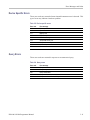
IEEE Common Commands
IEEE Common Commands
The IEEE 488.2 common commands have a "*" prefix.
Table 2-6: Status and error commands
Header
Description
*CAL?
Runs and returns the instrument normalization status.
*CLS
Clears status.
*ESE
Sets or queries the bits in the ESER register.
*ESR?
Returns the contents of the SESR register.
*IDN?
Returns the instrument identification code.
*OPC
Synchronizes commands.
*RST
Returns the instrument settings to the factory defaults.
*SRE
Sets or queries the bits in the SRER register.
*TRG
Generates a trigger.
*WAI
Prevents the instrument from executing further commands.
H500 & SA2500 Programmer Manual
2-11
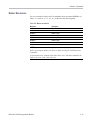
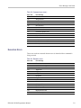
Abort Commands
Abort Commands
Use the Abort commands to reset the trigger system and to stop measurements.
Table 2-7: Abort commands
2-12
Header
Description
ABORt
Resets the trigger system and places the instrument in a paused
state.
H500 & SA2500 Programmer Manual
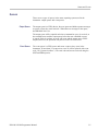
Calculate Commands
Calculate Commands
Use the Calculate commands to control the markers and the search operations.
Table 2-8: Calculate commands
Header
Description
CALCulate:AVTime subgroup
Amplitude vs. Time measurement
CALCulate:AVTime:MARKer<x>:MAXimum
Moves the marker to the highest peak on the trace.
CALCulate:AVTime:MARKer<x>:MODE
Sets or queries the markers absolute/delta readout mode.
CALCulate:AVTime:MARKer<x>:PEAK:HIGHer
Moves the marker to the next peak higher in amplitude on the trace.
CALCulate:AVTime:MARKer<x>:PEAK:LEFT
Moves the marker to the next peak to the left on the trace.
CALCulate:AVTime:MARKer<x>:PEAK:LOWer
Moves the marker to the next peak lower in amplitude on the trace.
CALCulate:AVTime:MARKer<x>:PEAK:RIGHt
Moves the marker to the next peak to the right on the trace.
CALCulate:AVTime:MARKer<x>:STATe
Sets or queries the enable/disable state of the marker.
CALCulate:AVTime:MARKer<x>:TRACE
Sets or queries the trace on which the specified marker is placed.
CALCulate:AVTime:MARKer<x>:X
Sets or queries the current time position of the specified marker.
CALCulate:AVTime:MARKer<x>:Y?
Queries the vertical position of the marker.
CALCulate:DPSA subgroup
DPX spectrum measurement
CALCulate:DPSA:MARKer<x>:MAXimum
Moves the marker to the highest peak on the trace.
CALCulate:DPSA:MARKer<x>:MODE
Sets or queries the markers absolute/delta readout mode.
CALCulate:DPSA:MARKer<x>:PEAK:HIGHer
Moves the marker to the next peak higher in amplitude on the trace.
CALCulate:DPSA:MARKer<x>:PEAK:LEFT
Moves the marker to the next peak to the left on the trace.
CALCulate:DPSA:MARKer<x>:PEAK:LOWer
Moves the marker to the next peak lower in amplitude on the trace.
CALCulate:DPSA:MARKer<x>:PEAK:RIGHt
Moves the marker to the next peak to the right on the trace.
CALCulate:DPSA:MARKer<x>[:SET]:CENTer
Sets the center frequency to the marker frequency.
CALCulate:DPSA:MARKer<x>:STATe
Sets or queries the enable/disable state of the marker.
CALCulate:DPSA:MARKer<x>:X
Sets or queries the frequency position of the marker.
CALCulate:DPSA:MARKer<x>:Y?
Queries the vertical position of the marker.
CALCulate:MARKer subgroup
CALCulate:MARKer:PEAK:THReshold
Sets or queries the threshold level to detect peaks.
CALCulate:SEARch subgroup
CALCulate:SEARch:LIMit:FAIL?
Query whether or not the current acquisition has a mask violation.
CALCulate:SEARch:LIMit:MATCh:BEEP[:STATe]
Sets or queries whether to beep when a mask violation occurs.
CALCulate:SEARch:LIMit:MATCh:SACQuire[:STATe]
Sets or queries whether to stop acquiring data when a mask violation
occurs.
CALCulate:SEARch:LIMit:MATCh:SPICture[:STATe]
Sets or queries whether to perform a screen save when a mask violation
occurs.
CALCulate:SEARch:LIMit:MATCh:STRace[:STATe]
Sets or queries whether to save the waveform trace when a mask
violation occurs.
CALCulate:SEARch:LIMit:OPERation:MASK:LOAD
Loads the spectrum mask from a specified file for the search operation.
H500 & SA2500 Programmer Manual
2-13
Calculate Commands
Table 2-8: Calculate commands (cont.)
Header
Description
CALCulate:SEARch:LIMit:STATe
Sets or queries whether to enable or disable the search function
(spectrum mask mode).
CALCulate:SPECtrum subgroup
Spectrum measurement
CALCulate:SPECtrum:MARKer<x>:MAXimum
Moves the specified marker to the highest peak on the trace.
CALCulate:SPECtrum:MARKer<x>:MODE
Sets or queries the markers absolute/delta readout mode.
CALCulate:SPECtrum:MARKer<x>:PEAK:HIGHer
Moves the marker to the next peak higher in amplitude on the trace.
CALCulate:SPECtrum:MARKer<x>:PEAK:LEFT
Moves the marker to the next peak to the left on the trace.
CALCulate:SPECtrum:MARKer<x>:PEAK:LOWer
Moves the marker to the next peak lower in amplitude on the trace.
CALCulate:SPECtrum:MARKer<x>:PEAK:RIGHt
Moves the marker to the next peak to the right on the trace.
CALCulate:SPECtrum:MARKer<x>[:SET]:CENTer
Sets the center frequency to the marker frequency.
CALCulate:SPECtrum:MARKer<x>:STATe
Sets or queries the enable/disable state of the marker.
CALCulate:SPECtrum:MARKer<x>:TRACe
Sets or queries the trace on which the marker is placed.
CALCulate:SPECtrum:MARKer<x>:X
Sets or queries the horizontal position of the marker.
CALCulate:SPECtrum:MARKer<x>:Y?
Queries the vertical position of the marker.
2-14
H500 & SA2500 Programmer Manual
Calculate Commands
Marker Mnemonics
Up to seven markers can be used. In commands, these are named MARKer<x>,
where <x> can be 0, 1, 2, 3, 4, 5, or 6 as shown in the following table.
Table 2-9: Marker mnemonics
Mnemonic
Description
MARKer0
Measurement frequency marker
MARKer1
Marker 1 (M1)
MARKer2
Marker 2 (M2)
MARKer3
Marker 3 (M3)
MARKer4
Marker 4 (M4)
MARKer5
Marker 5 (M5)
MARKer6
Marker 6 (M6)
NOTE. If you omit the numeric suffix, the marker control defaults to Marker 1.
Before operating the marker, you have to enable it using the CALCulate basic
commands.
If you attempt to use a marker other than above in a CALCulate command, the
suffix error (error code -130) will occur.
H500 & SA2500 Programmer Manual
2-15
Calibration Commands
Calibration Commands
Use the CALibration commands to control signal corrections.
Table 2-10: Calibration commands
Header
Description
CALibration:AUTO
Sets or queries the whether or not automatic normalizations should
occur.
CALibration:CORRection:EXTernal:GAIN[:MAGNitude]
Sets or queries the external gain/loss value.
CALibration:CORRection:EXTernal:GAIN:STATe
Sets or queries whether to enable or disable the external gain/loss value.
2-16
H500 & SA2500 Programmer Manual
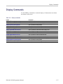
Display Commands
Display Commands
Use the DISPlay commands to control the display of measurement waveforms
and results on the screen.
Table 2-11: Display commands
Header
Description
DISPlay:AVTime subgroup
Amplitude vs. Time measurement
DISPlay:AVTime:MARKer:SHOW:STATe
Sets or queries the current marker display mode.
DISPlay:AVTime:Y[:SCALe]:OFFSet
Sets or queries the vertical position.
DISPlay:AVTime:Y[:SCALe]:PDIVision
Sets or queries the vertical scale (per division).
DISPlay:DPSA subgroup
DPX spectrum measurement
DISPlay:DPSA:MARKer:SHOW:STATe
Sets or queries the current DPSA marker display mode.
DISPlay:GENeral subgroup
General signal viewing
DISPlay:GENeral:MEASview:NEW
Sets the current measurement mode.
DISPlay:GENeral:MEASview:SELect
Sets or queries the current measurement mode.
DISPlay:SPECtrum subgroup
Spectrum measurement
DISPlay:SPECtrum:MARKer:SHOW:STATe
Sets or queries the current Spectrum marker display mode.
DISPlay:SPECtrum:Y[:SCALe]:OFFSet
Sets or queries the vertical position.
DISPlay:SPECtrum:Y[:SCALe]:PDIVision
Sets or queries the vertical scale (per division).
H500 & SA2500 Programmer Manual
2-17
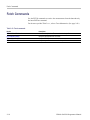
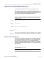
Fetch Commands
Fetch Commands
Use the FETCh commands to retrieve the measurements from the data taken by
the latest INITiate command.
For the trace specifier TRACe<x>, refer to Trace Mnemonics. (See page 2-28.)
Table 2-12: Fetch commands
Header
Description
FETCh:AVTime:TRACe<x>?
Queries the Amplitude vs. Time trace data for the specified trace.
FETCh:DPSA:BITMap?
Query the DPX Spectrum hit count data.
FETCh:DPSA:TRACe1?
Query the DPX Spectrum waveform data.
FETCh:SPECtrum:TRACe<x>?
Query the spectrum waveform data for the specified trace.
2-18
H500 & SA2500 Programmer Manual
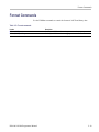
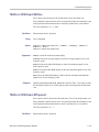
Format Commands
Format Commands
Use the FORMat commands to control the format of ASCII and binary data.
Table 2-13: Format commands
Header
Description
FORMat:[DATA]
Set binary or ASCII format for certain parameters and/or query responses.
FORMat:[DATA]:LOGGing
Set binary or ASCII format for data logging mode.
H500 & SA2500 Programmer Manual
2-19
Initiate Commands
Initiate Commands
Use the INITiate commands to control the acquisition of data.
Table 2-14: Initiate commands
2-20
Header
Description
INITiate:CONTinuous
Sets or queries whether to acquire data continuously.
INITiate[:IMMediate]
Starts data acquisition.
H500 & SA2500 Programmer Manual
Input Commands
Input Commands
Use the INPut commands to control the characteristics of the signal input.
Table 2-15: Input commands
Header
Description
INPut:ALEVel
Perform an auto-level.
INPut:RLEVel
Sets or queries the reference level.
RF: subgroup
INPut[:RF]:ATTenuation
Sets or queries the input attenuation.
INPut[:RF]:GAIN:STATe
Sets or queries whether to enable the internal preamplifier.
H500 & SA2500 Programmer Manual
2-21
Mass Memory Commands
Mass Memory Commands
Use the MMEMory commands to manipulate files on the mass memory devices.
For the trace specifier TRACe<x>, refer to Trace Mnemonics. (See page 2-28.)
Table 2-16: Mass memory (MMEMory) commands
Header
Description
MMEMory basic command subgroup
General file control
MMEMory:APPData:PREFix
Sets or queries the prefix to use for automatically generated filenames.
MMEMory:APPData:RESults
Sets or queries the default directory location for measurement results.
MMEMory:APPData:RESults:DEFault:EXPort:FORMat
Sets or queries the default measurement results ASCII export format.
MMEMory:APPData:RESults:DEFault:SCReen:
FORMat
Sets or queries the default screen image export format.
MMEMory:APPData:RESults:DELete
Deletes the specified file from the current measurement results directory.
MMEMory:APPData:RESults:EXISts?
Queries to see if a specified file exists in the current measurement results
directory.
MMEMory:APPData:RESults:INIT
Sets the measurement results directory to the factory default value.
MMEMory:APPData:SETTings
Sets or queries the default directory location for stored settings.
MMEMory:APPData:SETTings:DELete
Deletes a specified file from the current stored settings directory.
MMEMory:APPData:SETTings:EXISts?
Queries to see if a specified file exists in the current stored settings
directory.
MMEMory:APPData:SETTings:INIT
Sets the stored settings directory to the factory default value.
MMEMory:APPData:USERsettings
Set or queries the location of the default directory for user settings.
MMEMory:APPData:USERsettings:DELete
Deletes the specified file from the current user settings directory.
MMEMory:APPData:USERsettings:EXISts?
Queries to see if a specified file exists in the current user settings directory.
MMEMory:APPData:USERsettings:INIT
Sets the user settings directory to its factory default value.
MMEMory:DELete
Deletes the specified file from the specified path location.
MMEMory:EXISts?
Queries to see if a specified file exists at the specified path.
MMEMory:LOAD:RESults
Loads the previously stored measurement result from a specified file.
MMEMory:LOAD:STATe
Loads the instrument setup from a specified file.
MMEMory:SPECtrum:LOAD:TRACe<x>
Loads the spectrum trace data from the specified file.
MMEMory:STORe:IQ
Stores time-domain IQ data to a specified IQT-format file.
MMEMory:STORe:IQ:CSV
Stores time-domain IQ data to a specified CSV-format file.
MMEMory:STORe:IQ:MAT
Stores time-domain IQ data to a specified Matlab-format file.
MMEMory:STORe:RESults
Store the current measurement results in binary or ASCII format.
MMEMory:STORe:SCReen
Stores the screen image in a specified file.
MMEMory:STORe:STATe
Stores the instrument setup in a specified file.
2-22
H500 & SA2500 Programmer Manual
Output Commands
Output Commands
Use the OUTPut commands to control the characteristics of the signal output.
Table 2-17: Output commands
Header
Description
OUTPut:IF[:STATe]
Sets or queries whether to turn on or off IF output.
H500 & SA2500 Programmer Manual
2-23
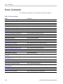
Sense Commands
Sense Commands
Use the SENSe commands to set up detailed measurement conditions.
Table 2-18: Sense commands
Header
Description
[SENSe] basic command subgroup
General analysis parameter control
[SENSe]:POWer:UNITs
Sets or queries the measurement unit of power.
[SENSe]:ROSCillator:SOURce?
Queries the reference oscillator source.
[SENSe]:AVTime subgroup
Amplitude vs. Time measurement
[SENSe]:AVTime:ACQuisition:MODE
Sets or queries the signal acquisition time mode.
[SENSe]:AVTime:ACQuisition:RATE?
Queries the measurement sample rate.
[SENSe]:AVTime:ACQuisition:SAMPles
Sets or queries the number of acquisition samples.
[SENSe]:AVTime:ACQuisition:SEConds
Sets or queries the acquisition time.
[SENSe]:AVTime:FREQuency:MEASurement
Sets or queries the measurement frequency.
[SENSe]:AVTime:FREQuency:SPAN
Sets or queries the measurement span.
[SENSe]:AVTime:MAX:SPAN
Sets the measurement frequency span to the maximum allowable span.
[SENSe]:DPSA subgroup
DPX spectrum measurement
[SENSe]:DPSA:CLEar:RESults
Resets the max hold or average trace and the bitmap.
[SENSe]:DPSA:COLor
Sets or queries the bitmap color mode.
[SENSe]:DPSA:COLor:MAXimum
Sets or queries the maximum value of the color axis.
[SENSe]:DPSA:COLor:MINimum
Sets or queries the minimum value of the color axis.
[SENSe]:DPSA:FREQuency:CENTer
Sets or queries the center frequency.
[SENSe]:DPSA:FREQuency:MEASurement
Sets or queries the measurement frequency.
[SENSe]:DPSA:FREQuency:SPAN
Sets or queries the frequency span.
[SENSe]:DPSA:MAX:SPAN
Sets the frequency span to the maximum span.
[SENSe]:SPECtrum subgroup
Spectrum measurement
[SENSe]:SPECtrum:{BANDwidth|BWIDth}[:
RESolution]
Sets or queries the resolution bandwidth (RBW).
[SENSe]:SPECtrum:{BANDwidth|BWIDth}[:
RESolution]:AUTO
Sets or queries whether to set the RBW automatically.
[SENSe]:SPECtrum:FREQuency:CENTer
Sets or queries the center frequency.
[SENSe]:SPECtrum:FREQuency:MEASurement
Sets or queries the measurement frequency.
[SENSe]:SPECtrum:FREQuency:SPAN
Sets or queries the frequency span.
[SENSe]:SPECtrum:FREQuency:SPAN:BANDwidth[:
RESolution]:RATio
Sets or queries the ratio of span to RBW.
[SENSe]:SPECtrum:FREQuency:STARt
Sets or queries the measurement start frequency.
[SENSe]:SPECtrum:FREQuency:STOP
Sets or queries the measurement stop frequency.
[SENSe]:SPECtrum:MAX:SPAN
Sets the frequency span to the maximum span.
2-24
H500 & SA2500 Programmer Manual
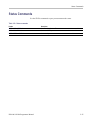
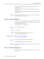
Status Commands
Status Commands
Use the STATus commands to query measurement mode status.
Table 2-19: Status commands
Header
Description
STATus:AVTime:EVENts?
Queries the Amplitude vs. Time measurement event and status condition.
STATus:DPSA:EVENts?
Queries the DPX Spectrum measurement event and status condition.
STATus:SPECtrum:EVENts?
Queries the Spectrum measurement event and status condition.
H500 & SA2500 Programmer Manual
2-25
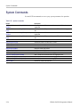
System Commands
System Commands
Use the SYSTem commands to set or query system parameters for operation.
Table 2-20: System commands
Header
Description
SYSTem:COMMunicate:LOGGing:GPS[:SOCKet]:
ADDRess
Sets or queries the UDP address at which to store the GPS time/location
logging files.
SYSTem:COMMunicate:LOGGing:GPS[:SOCKet]:
PORT
Sets or queries the UDP port at which to store GPS time/location logging
files.
SYSTem:COMMunicate:LOGGing:RESults[:SOCKet]:
ADDRess
Sets or queries the UDP address at which to store the measurement result
logging files.
SYSTem:COMMunicate:LOGGing:RESults[:SOCKet]:
PORT
Sets or queries the UDP port at which to store GPS time/location logging
files.
SYSTem:DATE?
Queries the current instrument date.
SYSTem:ERRor:COUNt?
Queries the number of unread errors or events.
SYSTem:ERRor[:NEXT]?
Queries the latest error or event information.
SYSTem:GPS
Sets or queries the GPS operational mode.
SYSTem:GPS:POSition?
Query the current GPS position.
SYSTem:GPS:STATus?
Query the current GPS status.
SYSTem:LOGGing:GPS
Sets or queries the GPS time/location logging mode.
SYSTem:LOGGing:GPS:FILE[:NAME]
Sets or queries the GPS time/location data logging file name.
SYSTem:LOGGing:RESults
Sets or queries the measurement result logging mode.
SYSTem:LOGGing:RESults:FILE[:NAME]
Sets or queries measurement results logging file name.
SYSTem:TIME?
Queries the current instrument time.
2-26
H500 & SA2500 Programmer Manual
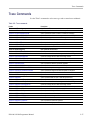
Trace Commands
Trace Commands
Use the TRACe commands to select trace type and to control trace arithmetic.
Table 2-21: Trace commands
Header
Description
TRACe<x>:AVTime subgroup
Amplitude vs. Time measurement
TRACe<x>:AVTime
Sets or queries whether to show or hide the specified trace.
TRACe<x>:AVTime:AVERage:COUNt
Sets or queries the number of traces to combine for averaging.
TRACe<x>:AVTime:AVERage:PROGress?
Queries the number of times the average trace has been averaged.
TRACe<x>:AVTime:AVERage:RESet
Clears the average data and resets the average counter.
TRACe<x>:AVTime:COUNt:RESet
Clears the Max or Min Hold data and counter, and restarts the process.
TRACe<x>:AVTime:DETection
Sets or queries the detection (decimate) algorithm.
TRACe<x>:AVTime:FOReground
Sets or queries the foreground trace.
TRACe<x>:AVTime:FUNCtion
Sets or queries the trace function.
TRACe<x>:DPSA subgroup
DPX spectrum measurement
TRACe<x>:DPSA:AVERage:COUNt
Sets or queries the number of traces to combine for averaging.
TRACe<x>:DPSA:AVERage:PROGress?
Queries the number of times the average trace has been averaged.
TRACe<x>:DPSA:AVERage:RESet
Clears the average data and resets the average counter.
TRACe<x>:DPSA:COLor:INTensity
Sets or queries the color intensity.
TRACe<x>:DPSA:COUNt:RESet
Clears the Max Hold data and counter, and restarts the process.
TRACe<x>:DPSA:DETection
Sets or queries the detection (decimate) algorithm.
TRACe<x>:DPSA:DOT:PERSistent
Sets or queries whether to enable or disable dot persistence mode.
TRACe<x>:DPSA:DOT:PERSistent:TYPE
Sets or queries the persistence type.
TRACe<x>:DPSA:DOT:PERSistent:VARiable
Sets or queries the length of time that data points are displayed.
TRACe<x>:DPSA:FUNCtion
Sets or queries the trace function.
TRACe<x>:SPECtrum subgroup
Spectrum measurement
TRACe<x>:SPECtrum
Sets or queries whether to show or hide the specified trace.
TRACe<x>:SPECtrum:AVERage:COUNt
Sets or queries the number of traces to combine for averaging.
TRACe<x>:SPECtrum:AVERage:PROGress?
Queries the number of times the average trace has been averaged.
TRACe<x>:SPECtrum:AVERage:RESet
Clears the average data and resets the average counter.
TRACe<x>:SPECtrum:COUNt:RESet
Clears the Max or Min Hold data and counter, and restarts the process.
TRACe<x>:SPECtrum:DETection
Sets or queries the detection (decimate) algorithm.
TRACe<x>:SPECtrum:FOReground
Sets or queries the foreground trace.
TRACe<x>:SPECtrum:FUNCtion
Sets or queries the trace function.
TRACe<x>:SPECtrum:LEFToperand
Sets or queries the left operand for the math trace.
TRACe<x>:SPECtrum:LOAD:TRACe
Load a live trace into a reference trace.
TRACe<x>:SPECtrum:OPERation
Sets or queries the math trace operation.
TRACe<x>:SPECtrum:RIGHtoperand
Sets or queries the right operand for the math trace.
H500 & SA2500 Programmer Manual
2-27
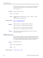
Trace Commands
Trace Mnemonics
Multiple traces can be used in some measurement modes. The traces are
specified by the trace specifier TRACe<x> (<x>=1 to 5) which is defined for
each measurement display as follows.
Table 2-22: Trace mnemonics
Measurement mode
TRACe1
TRACe2
TRACe3
TRACe4
TRACe5
Amplitude vs. Time
Trace 1
Trace 2
NA
NA
NA
DPX Spectrum
Trace 1
NA
NA
NA
Bitmap trace
Spectrum
Trace 1
Trace 2
Ref A
Ref B
Math
NOTE. Valid traces depend on commands. Refer to each command description.
2-28
H500 & SA2500 Programmer Manual
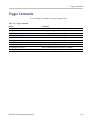
Trigger Commands
Trigger Commands
Use the TRIGger commands to set up the trigger system.
Table 2-23: Trigger commands
Header
Description
TRIGger[:SEQuence]:EVENt:EXTernal:SLOPe
Sets or queries the external trigger slope type.
TRIGger[:SEQuence]:EVENt:INPut:LEVel
Sets or queries the trigger level for the IF input level trigger.
TRIGger[:SEQuence]:EVENt:INPut:SLOPe
Sets or queries the trigger slope for the IF input level trigger.
TRIGger[:SEQuence]:EVENt:INTernal
Sets or queries the internal time base trigger mode.
TRIGger[:SEQuence]:EVENt:INTernal:REPeat
Sets or queries the internal time base trigger repeat interval time.
TRIGger[:SEQuence]:EVENt:INTernal:TIME
Sets or queries the internal time base trigger start time.
TRIGger[:SEQuence]:EVENt:SOURce
Sets or queries the trigger event source.
TRIGger[:SEQuence]:IMMediate
Causes a trigger immediately.
TRIGger[:SEQuence]:STATus
Sets or queries the trigger mode (Free Run or Triggered).
TRIGger[:SEQuence]:TIME:DELay
Sets or queries the trigger delay time.
H500 & SA2500 Programmer Manual
2-29
Unit Commands
Unit Commands
Specify fundamental units for measurement.
Table 2-24: Unit commands
2-30
Header
Description
UNIT:POWer
Sets or queries the measurement unit of power.
H500 & SA2500 Programmer Manual
Command Descriptions
ABORt (No Query Form)
Resets the trigger system and places the instrument in a paused state. Any actions
related to the trigger system that are in progress, such as acquiring a measurement,
are also aborted.
To start data acquisition, use the INITiate commands.
Conditions
Measurement modes: All
Group
Abort commands
Syntax
ABORt
Related Commands
Arguments
Examples
INITiate:CONTinuous
INITiate[:IMMediate]
None
ABORT resets the trigger system and stops data acquisition.
*CAL? (Query Only)
Runs and returns the instrument normalization status.
Conditions
Spectrum and Amplitude vs. Time modes
Group
IEEE common commands
Syntax
*CAL?
Arguments
Returns
None
<NR1>, where:
1 indicates the instrument has completed a measurement normalization process
with no errors.
H500 & SA2500 Programmer Manual
2-31
Command Descriptions
0 indicates the instrument has completed a measurement normalization process
with errors, or normalization on the instrument is disabled, or the instrument is not
in Spectrum or Amplitude vs. Time mode.
Examples
*CAL? might return 1 indicating that the instrument has completed a measurement
normalization process with no errors.
CALCulate:AVTime:MARKer<x>:MAXimum (No Query Form)
Moves the specified Amplitude vs. Time mode marker to the maximum peak on
the Amplitude vs. Time trace. Valid marker <x> values are 1 through 6.
This command is ignored, and an error event generated, when the specified
marker is not enabled, marker display is disabled, or the instrument is not in
Amplitude vs. Time mode.
Conditions
Measurement modes: Amplitude vs. Time
Group
Calculate commands
Syntax
CALCulate:AVTime:MARKer<x>:MAXimum
Arguments
Examples
None
CALCulate:AVTime:MARKer3:MAXimum moves Marker 3 (M3) to the highest
peak on the Amplitude vs. Time trace.
CALCulate:AVTime:MARKer<x>:MODE
Sets or queries the specified Amplitude vs. Time marker to absolute or delta
measurement mode (in relation to Marker 1). Valid marker <x> values are 1
through 6. Marker 1 is always absolute.
This command is ignored and an error event generated when the specified marker
is not enabled, marker display is disabled, or the instrument is not in Amplitude
vs. Time mode.
Conditions
Group
2-32
Measurement modes: Amplitude vs. Time
Calculate commands
H500 & SA2500 Programmer Manual
Command Descriptions
Syntax
Arguments
CALCulate:AVTime:MARKer<x>:MODE { ABSolute | DELTa }
CALCulate:AVTime:MARKer<x>:MODE?
ABSolute sets the specified marker to absolute measurement mode.
DELTa sets the specified marker to delta measurement mode, in relation to marker
1.
Examples
CALCULATE:AVTime:MARKER4:MODE ABSolute sets Marker 4 (M4) to
measure the absolute value at the specified marker position.
CALCULATE:AVTime:MARKER3:MODE? might return DELT, indicating that the
specified marker is set to delta measurement mode.
CALCulate:AVTime:MARKer<x>:PEAK:HIGHer (No Query Form)
Moves the specified marker to the next peak on the Amplitude vs. Time trace that
is higher than the current marker position and is above the current marker peak
threshold. Valid marker <x> values are 1 through 6.
This command is ignored and an error event generated when the specified marker
is not enabled, marker display is disabled, or the instrument is not in Amplitude
vs. Time mode.
Conditions
Measurement modes: Amplitude vs. Time
Group
Calculate commands
Syntax
CALCulate:AVTime:MARKer<x>:PEAK:HIGHer
Related Commands
Arguments
Examples
CALCulate:AVTime:MARKer<x>:PEAK:LEFT
CALCulate:AVTime:MARKer<x>:PEAK:LOWer
CALCulate:AVTime:MARKer<x>:PEAK:RIGHt
CALCulate:MARKer:PEAK:THReshold
None
CALCULATE:AVTime:MARKER2:PEAK:HIGHER moves Marker 2 (M2) to the
next peak higher in amplitude on the trace.
H500 & SA2500 Programmer Manual
2-33
Command Descriptions
CALCulate:AVTime:MARKer<x>:PEAK:LEFT (No Query Form)
Moves the specified marker to the next peak on the Amplitude vs. Time trace that
is to the left of the current marker position and is above the current marker peak
threshold. Valid marker <x> values are 1 through 6.
This command is ignored and an error event generated when the specified marker
is not enabled, marker display is disabled, or the instrument is not in Amplitude
vs. Time mode.
Conditions
Measurement modes: Amplitude vs. Time
Group
Calculate commands
Syntax
CALCulate:AVTime:MARKer<x>:PEAK:LEFT
Related Commands
Arguments
Examples
CALCulate:AVTime:MARKer<x>:PEAK:HIGHer
CALCulate:AVTime:MARKer<x>:PEAK:LOWer
CALCulate:AVTime:MARKer<x>:PEAK:RIGHt
CALCulate:MARKer:PEAK:THReshold
None
CALCULATE:AVTime:MARKER5:PEAK:LEFT moves Marker 5 (M5) to the next
peak to the left on the trace.
CALCulate:AVTime:MARKer<x>:PEAK:LOWer (No Query Form)
Moves the specified marker to the next peak on the Amplitude vs. Time trace that
is lower than the current marker position and is above the current marker peak
threshold. Valid marker <x> values are 1 through 6.
This command is ignored and an error event generated when the specified marker
is not enabled, marker display is disabled, or the instrument is not in Amplitude
vs. Time mode.
Conditions
2-34
Measurement modes: Amplitude vs. Time
Group
Calculate commands
Syntax
CALCulate:AVTime:MARKer<x>:PEAK:LOWer
H500 & SA2500 Programmer Manual
Command Descriptions
Related Commands
Arguments
Examples
CALCulate:AVTime:MARKer<x>:PEAK:HIGHer
CALCulate:AVTime:MARKer<x>:PEAK:LEFT
CALCulate:AVTime:MARKer<x>:PEAK:RIGHt
CALCulate:MARKer:PEAK:THReshold
None
CALCULATE:AVTime:MARKER2:PEAK:LOWER moves Marker 2 (M2) to the next
peak lower in amplitude on the trace.
CALCulate:AVTime:MARKer<x>:PEAK:RIGHt (No Query Form)
Moves the specified marker to the next peak on the Amplitude vs. Time trace that
is to the right of the current marker position and is above the current marker peak
threshold. Valid marker <x> values are 1 through 6.
This command is ignored and an error event generated when the specified marker
is not enabled, marker display is disabled, or the instrument is not in Amplitude
vs. Time mode.
Conditions
Measurement modes: Amplitude vs. Time
Group
Calculate commands
Syntax
CALCulate:AVTime:MARKer<x>:PEAK:RIGHt
Related Commands
Arguments
Examples
CALCulate:AVTime:MARKer<x>:PEAK:HIGHer
CALCulate:AVTime:MARKer<x>:PEAK:LEFT
CALCulate:AVTime:MARKer<x>:PEAK:LOWer
CALCulate:MARKer:PEAK:THReshold
None
CALCULATE:AVTime:MARKER2:PEAK:RIGHT moves Marker 2 (M2) to the next
peak to the right on the trace.
CALCulate:AVTime:MARKer<x>:STATe
Sets or queries the enable/disable state of the specified Amplitude vs. Time mode
marker. Valid marker <x> values are 1 through 6.
H500 & SA2500 Programmer Manual
2-35
Command Descriptions
This command is ignored and an error event generated when the instrument is not
in Amplitude vs. Time mode.
Conditions
Measurement modes: Amplitude vs. Time
Group
Calculate commands
Syntax
CALCulate:AVTime:MARKer<x>:STATe { OFF | ON | 0 | 1 }
CALCulate:AVTime:MARKer<x>:STATe?
Arguments
ON or 1 enables the specified marker.
OFF or 0 disables the specified marker.
Examples
CALCulate:AVTime:MARKer5:STATe ON enables Marker 5 (M5).
CALCulate:AVTime:MARKer2:STATe? might return 0 to indicate that Marker
2 (M2) is not enabled.
CALCulate:AVTime:MARKer<x>:TRACE
Sets or queries the trace on which the specified marker is placed in the Amplitude
vs. Time measurement mode. Valid marker <x> values are 1 through 6.
This command is ignored and an error event generated when the instrument is not
in Amplitude vs. Time measurement mode, the display or markers are currently
disabled, the specified marker is not enabled, or the specified trace is not enabled.
Conditions
Measurement modes: Amplitude vs. Time
Group
Calculate commands
Syntax
CALCulate:AVTime:MARKer<x>:TRACE { TRACe1 | TRACe2 |
FOReground }
CALCulate:AVTime:MARKer<x>:TRACE?
Arguments
TRACe1 places the specified marker on Trace 1.
TRACe2 places the specified marker on Trace 2.
FOReground places the specified marker on the front-most (selected) trace.
2-36
H500 & SA2500 Programmer Manual
Command Descriptions
Examples
CALCulate:AVTime:MARKer1:TRACE TRACe1 places Marker 1 (M1) on
Trace 1.
CALCULATE:AVTime:MARKER2:TRACE? might return TRAC2, indicating that the
marker is on the Trace 2 waveform.
CALCulate:AVTime:MARKer<x>:X
Sets or queries the time value at the position of the Amplitude vs. Time mode
marker on the Amplitude vs. Time trace. Valid marker <x> values are 1 through 6.
When the specified maker is enabled and set to absolute marker mode, the return
value of the query is a NRf type equal to the specified markers current time. When
the specified maker is enabled and set to delta marker mode, the return value of
the query is a NRf type equal to the difference between the specified marker
time and the marker 1 time.
This command is ignored and an error event generated when the specified marker
is not enabled, marker display is disabled, or the instrument is not in Amplitude
vs. Time mode.
Conditions
Measurement modes: Amplitude vs. Time
Group
Calculate commands
Syntax
CALCulate:AVTime:MARKer<x>:X <value>
CALCulate:AVTime:MARKer<x>:X?
Related Commands
Arguments
Examples
CALCulate:AVTime:MARKer<x>:Y?
<value>::=<NRf> specifies the horizontal (time) position of the marker.
Range: allowable time range of the instrument.
CALCULATE:AVTime:MARKER3:X 100e-3 places Marker 3 (M3) at the 100 ms
position on the Amplitude vs. Time trace.
CALCulate:AVTime:MARKer<x>:Y? (Query Only)
Queries the vertical position (amplitude) of the specified marker in the Amplitude
vs. Time trace. Valid marker <x> values are 1 through 6.
When the specified maker is enabled and set to absolute marker mode, the return
value of the query is a NRf type equal to the specified markers current amplitude.
H500 & SA2500 Programmer Manual
2-37
Command Descriptions
When the specified maker is enabled and set to delta marker mode, the return
value of the query is a NRf type equal to the difference between the specified
marker amplitude and the marker 1 amplitude.
This command is ignored and an error event generated when the specified marker
is not enabled, marker display is disabled, or the instrument is not in Amplitude
vs. Time mode.
Conditions
Measurement modes: Amplitude vs. Time
Group
Calculate commands
Syntax
CALCulate:AVTime:MARKer<x>:Y?
Related Commands
Arguments
Returns
Examples
CALCulate:AVTime:MARKer<x>:X
None
<NRf> specifies the markers absolute or delta amplitude, in current power units,
as specified by the UNIT:POWER command.
CALCULATE:AVTime:MARKER1:Y? might return -34.28, indicating that Marker
1 (M1) is at -34.28 dBm.
CALCulate:DPSA:MARKer<x>:MAXimum (No Query Form)
Moves the specified DPX mode marker to the maximum peak on the DPX
spectrum trace. Valid marker <x> values are 0 through 6.
This command is ignored and an error event generated when the specified
marker is not enabled, marker display is disabled, or the instrument is not in
DPX Spectrum mode.
Conditions
2-38
Measurement modes: DPX Spectrum
Group
Calculate commands
Syntax
CALCulate:DPSA:MARKer<x>:MAXimum
H500 & SA2500 Programmer Manual
Command Descriptions
Arguments
Examples
None
CALCULATE:DPSA:MARKER3:MAXIMUM moves Marker 3 (M3) to the highest
peak on the DPX Spectrum trace.
CALCulate:DPSA:MARKer<x>:MODE
Sets or queries the specified DPX marker to absolute or delta measurement mode
(in relation to Marker 1). Valid marker <x> values are 1 through 6. Marker 1 is
always absolute.
This command is ignored and an error event generated when the specified
marker is not enabled, marker display is disabled, or the instrument is not in
DPX Spectrum mode.
Conditions
Measurement modes: DPX Spectrum
Group
Calculate commands
Syntax
CALCulate:DPSA:MARKer<x>:MODE { ABSolute | DELTa }
CALCulate:DPSA:MARKer<x>:MODE?
Arguments
ABSolute sets the specified marker to absolute measurement mode.
DELTa sets the specified marker to delta measurement mode, in relation to marker
1.
Examples
CALCULATE:DPSA:MARKER4:MODE ABSolute sets Marker 4 (M4) to measure
the absolute value at the specified marker position.
CALCULATE:DPSA:MARKER3:MODE? might return DELT, indicating that the
specified marker is set to delta measurement mode.
CALCulate:DPSA:MARKer<x>:PEAK:HIGHer (No Query Form)
Moves the specified marker to the next peak on the DPX spectrum trace that is
higher than the current marker position and is above the current marker peak
threshold. Valid marker <x> values are 0 through 6.
This command is ignored and an error event generated when the specified
marker is not enabled, marker display is disabled, or the instrument is not in
DPX Spectrum mode.
H500 & SA2500 Programmer Manual
2-39
Command Descriptions
Conditions
Measurement modes: DPX Spectrum
Group
Calculate commands
Syntax
CALCulate:DPSA:MARKer<x>:PEAK:HIGHer
Related Commands
Arguments
Examples
CALCulate:AVTime:MARKer<x>:PEAK:LOWer
CALCulate:MARKer:PEAK:THReshold
None
CALCULATE:DPSA:MARKER2:PEAK:HIGHER moves Marker 2 (M2) to the next
peak higher in amplitude on the trace.
CALCulate:DPSA:MARKer<x>:PEAK:LEFT (No Query Form)
Moves the specified marker to the next peak on the DPX spectrum trace that is
to the left of the current marker position and is above the current marker peak
threshold. Valid marker <x> values are 0 through 6.
This command is ignored and an error event generated when the specified
marker is not enabled, marker display is disabled, or the instrument is not in
DPX Spectrum mode.
Conditions
Group
Calculate commands
Syntax
CALCulate:DPSA:MARKer<x>:PEAK:LEFT
Related Commands
Arguments
Examples
2-40
Measurement modes: DPX Spectrum
CALCulate:AVTime:MARKer<x>:PEAK:RIGHt
CALCulate:MARKer:PEAK:THReshold
None
CALCULATE:DPSA:MARKER5:PEAK:LEFT moves Marker 5 (M5) to the next
peak to the left on the trace.
H500 & SA2500 Programmer Manual
Command Descriptions
CALCulate:DPSA:MARKer<x>:PEAK:LOWer (No Query Form)
Moves the specified marker to the next peak on the DPX spectrum trace that
is lower than the current marker position and is above the current marker peak
threshold. Valid marker <x> values are 0 through 6.
This command is ignored and an error event generated when the specified
marker is not enabled, marker display is disabled, or the instrument is not in
DPX Spectrum mode.
Conditions
Measurement modes: DPX Spectrum
Group
Calculate commands
Syntax
CALCulate:DPSA:MARKer<x>:PEAK:LOWer
Related Commands
Arguments
Examples
CALCulate:AVTime:MARKer<x>:PEAK:HIGHer
CALCulate:MARKer:PEAK:THReshold
None
CALCULATE:DPSA:MARKER2:PEAK:LOWER moves Marker 2 (M2) to the next
peak lower in amplitude on the trace.
CALCulate:DPSA:MARKer<x>:PEAK:RIGHt (No Query Form)
Moves the specified marker to the next peak on the DPX spectrum trace that is
to the right of the current marker position and is above the current marker peak
threshold. Valid marker <x> values are 0 through 6.
This command is ignored and an error event generated when the specified
marker is not enabled, marker display is disabled, or the instrument is not in
DPX Spectrum mode.
Conditions
Measurement modes: DPX Spectrum
Group
Calculate commands
Syntax
CALCulate:DPSA:MARKer<x>:PEAK:RIGHt
H500 & SA2500 Programmer Manual
2-41
Command Descriptions
Related Commands
Arguments
Examples
CALCulate:AVTime:MARKer<x>:PEAK:LEFT
CALCulate:MARKer:PEAK:THReshold
None
CALCULATE:DPSA:MARKER2:PEAK:RIGHT moves Marker 2 (M2) to the next
peak to the right on the trace.
CALCulate:DPSA:MARKer<x>[:SET]:CENTer (No Query Form)
Sets the measurement center frequency to that of the specified DPX mode marker
frequency. Valid marker <x> values are 0 through 6.
This command is ignored and an error event generated when the specified
marker is not enabled, marker display is disabled, or the instrument is not in
DPX Spectrum mode.
Conditions
Measurement modes: DPX Spectrum
Group
Calculate commands
Syntax
CALCulate:DPSA:MARKer<x>[:SET]:CENTer
Arguments
Examples
None
CALCULATE:DPSA:MARKER1:SET:CENTER sets the center frequency to the
frequency of marker 1.
CALCulate:DPSA:MARKer<x>:STATe
Sets or queries the enable/disable state of the specified DPX mode marker. Valid
marker <x> values are 0 through 6.
This command is ignored and an error event generated when the instrument is
not in DPX Spectrum mode.
Conditions
Group
2-42
Measurement modes: DPX Spectrum
Calculate commands
H500 & SA2500 Programmer Manual
Command Descriptions
Syntax
Arguments
CALCulate:DPSA:MARKer<x>:STATe { OFF | ON | 0 | 1 }
CALCulate:DPSA:MARKer<x>:STATe?
ON or 1 enables the specified marker.
OFF or 0 disables the specified marker.
Examples
CALCulate:DPSA:MARKer5:STATe ON enables Marker 5 (M5).
CALCulate:DPSA:MARKer2:STATe? might return 0 to indicate that Marker
2 (M2) is not enabled.
CALCulate:DPSA:MARKer<x>:X
Sets or queries the frequency value at the position of the specified marker in the
DPX spectrum view. Valid marker <x> values are 0 through 6.
When the specified maker is enabled and set to absolute marker mode, the return
value of the query is a NRf type equal to the specified markers current frequency.
When the specified maker is enabled and set to delta marker mode, the return
value of the query is a NRf type equal to the difference between the specified
markers frequency and the marker 1 frequency.
This command is ignored and an error event generated when the specified
marker is not enabled, marker display is disabled, or the instrument is not in
DPX Spectrum mode.
Conditions
Measurement modes: DPX Spectrum
Group
Calculate commands
Syntax
CALCulate:DPSA:MARKer<x>:X <value>
CALCulate:DPSA:MARKer<x>:X?
Related Commands
Arguments
Examples
CALCulate:AVTime:MARKer<x>:Y?
<value>::=<NRf> specifies the frequency position of the marker.
Range: allowable frequency range of the instrument.
CALCULATE:DPSA:MARKER3:X:FREQUENCY 800e6 places Marker 3 (M3)
at 800 MHz.
H500 & SA2500 Programmer Manual
2-43
Command Descriptions
CALCulate:DPSA:MARKer<x>:Y? (Query Only)
Queries the amplitude (vertical) value at the position of the specified marker in the
DPX spectrum view. Valid marker <x> values are 0 through 6.
When the specified maker is enabled and set to absolute marker mode, the return
value of the query is a NRf type equal to the specified markers current amplitude.
When the specified maker is enabled and set to delta marker mode, the return
value of the query is a NRf type equal to the difference between the specified
markers amplitude and the marker 1 amplitude.
This command is ignored and an error event generated when the specified
marker is not enabled, marker display is disabled, or the instrument is not in
DPX Spectrum mode.
Conditions
Measurement modes: DPX Spectrum
Group
Calculate commands
Syntax
CALCulate:DPSA:MARKer<x>:Y?
Arguments
Returns
Examples
None
<NRf> The specified markers absolute or delta amplitude, in current power units,
as specified by the UNIT:POWER command.
CALCULATE:DPSA:MARKER1:Y? might return -34.28, indicating that Marker 1
(M1) is at -34.28 dBm of the DPX waveform trace.
CALCulate:MARKer:PEAK:THReshold
Sets or queries the threshold value that determines the minimum peak amplitude
for marker peak searches.
Conditions
2-44
Measurement modes: All
Group
Calculate commands
Syntax
CALCulate:MARKer:PEAK:THReshold <value>
CALCulate:MARKer:PEAK:THReshold?
H500 & SA2500 Programmer Manual
Command Descriptions
Related Commands
Arguments
Examples
CALCulate:AVTime:MARKer<x>:PEAK:HIGHer
CALCulate:AVTime:MARKer<x>:PEAK:LEFT
CALCulate:AVTime:MARKer<x>:PEAK:LOWer
CALCulate:AVTime:MARKer<x>:PEAK:RIGHt
CALCulate:DPSA:MARKer<x>:PEAK:HIGHer
CALCulate:DPSA:MARKer<x>:PEAK:LEFT
CALCulate:DPSA:MARKer<x>:PEAK:LOWer
CALCulate:DPSA:MARKer<x>:PEAK:RIGHt
CALCulate:SPECtrum:MARKer<x>:PEAK:HIGHer
CALCulate:SPECtrum:MARKer<x>:PEAK:LEFT
CALCulate:SPECtrum:MARKer<x>:PEAK:LOWer
CALCulate:SPECtrum:MARKer<x>:PEAK:RIGHt
<value>::=<NRf> specifies the minimum threshold level for detecting peaks.
The threshold value uses the current power units.
Range: -170 to +20 dBm.
CALCULATE:MARKER:PEAK:THRESHOLD -50 sets the minimum threshold level
to -50 dBm.
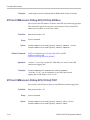
CALCulate:SEARch:LIMit:FAIL? (Query Only)
Queries whether or not the current acquisition has a Spectrum mask violation.
Conditions
Measurement modes: Spectrum and DPX Spectrum
Group
Calculate commands
Syntax
CALCulate:SEARch:LIMit:FAIL?
Arguments
Returns
Examples
None
<boolean> where 0 represents a spectrum mask limit violation on trace 1, and
1 indicates no mask limit violations on trace 1.
CALCulate:SEARch:LIMit:FAIL? might return 0 to indicate that trace 1
violates the current spectrum mask or if mask testing is not enabled.
H500 & SA2500 Programmer Manual
2-45
Command Descriptions
CALCulate:SEARch:LIMit:MATCh:BEEP[:STATe]
Sets or queries whether or not to beep when a spectrum mask violation occurs.
Conditions
Measurement modes: Spectrum and DPX Spectrum
Group
Calculate commands
Syntax
CALCulate:SEARch:LIMit:MATCh:BEEP[:STATe] { OFF | ON | 0 |
1 }
CALCulate:SEARch:LIMit:MATCh:BEEP[:STATe]?
Arguments
ON or 1 enables the instrument to sound a beep when a mask test violation occurs.
OFF or 0 disables the instrument from sounding a beep when a mask test violation
occurs.
Examples
CALCULATE:SEARCH:LIMIT:MATCH:BEEP:STATE 1 sets the instrument to
sound a beep when a mask test violation occurs.
CALCULATE:SEARCH:LIMIT:MATCH:BEEP? might return a 0, indicating that the
instrument sound beep on mask test violation parameter is disabled.
CALCulate:SEARch:LIMit:MATCh:SACQuire[:STATe]
Sets or queries whether or not to pause acquisitions when a spectrum mask
violation occurs.
Conditions
Measurement modes: Spectrum and DPX Spectrum
Group
Calculate commands
Syntax
CALCulate:SEARch:LIMit:MATCh:SACQuire[:STATe] { OFF | ON |
0 | 1 }
CALCulate:SEARch:LIMit:MATCh:SACQuire[:STATe]?
Arguments
ON or 1 sets the instrument to pause acquisition when a mask test violation occurs.
OFF or 0 sets the instrument to continue measurement acquisition when a mask
test violation occurs.
2-46
H500 & SA2500 Programmer Manual
Command Descriptions
Examples
CALCULATE:SEARCH:LIMIT:MATCH:SACQUIRE:STATE 1 sets the instrument
to pause acquisition when a mask test violation occurs.
CALCULATE:SEARCH:LIMIT:MATCH:SACQUIRE? might return a 0, indicating
that the instrument is set to continue measurement acquisition when a mask test
violation occurs.
CALCulate:SEARch:LIMit:MATCh:SPICture[:STATe]
Sets or queries whether or not to export a screen image when a spectrum mask
violation occurs.
Conditions
Measurement modes: Spectrum and DPX Spectrum
Group
Calculate commands
Syntax
CALCulate:SEARch:LIMit:MATCh:SPICture[:STATe] { OFF | ON |
0 | 1 }
CALCulate:SEARch:LIMit:MATCh:SPICture[:STATe]?
Arguments
ON or 1 sets the instrument to automatically save a screen shot of spectrum mask
violations when a mask test violation occurs.
OFF or 0 sets the instrument to not automatically save a screen shot of the mask
violations when a mask test violation occurs.
Examples
CALCULATE:SEARCH:LIMIT:MATCH:SPICTURE:STATE ON sets the instrument
to automatically save a screen shot of spectrum mask violations when a mask test
violation occurs.
CALCULATE:SEARCH:LIMIT:MATCH:SPICTURE? might return a 0, indicating
that the instrument is set to continue measurement acquisition without saving a
screen shot of the mask violations when a mask test violation occurs.
CALCulate:SEARch:LIMit:MATCh:STRace[:STATe]
Sets or queries whether or not to export the current measurement results when a
spectrum mask violation occurs.
Conditions
Group
Measurement modes: Spectrum and DPX Spectrum
Calculate commands
H500 & SA2500 Programmer Manual
2-47
Command Descriptions
Syntax
Arguments
CALCulate:SEARch:LIMit:MATCh:STRace[:STATe] { OFF | ON | 0 |
1 }
CALCulate:SEARch:LIMit:MATCh:STRace[:STATe]?
ON or 1 sets the instrument to automatically export measurement results of
spectrum mask violations to a file when a mask test violation occurs.
OFF or 0 sets the instrument to not export measurement results of spectrum mask
violations to a file when a mask test violation occurs.
Examples
CALCULATE:SEARCH:LIMIT:MATCH:STRACE:STATE ON sets the instrument to
export measurement results of spectrum mask violations to a file when a mask test
violation occurs.
CALCULATE:SEARCH:LIMIT:MATCH:STRACE? might return a 1, indicating that
the instrument is set to export measurement results of spectrum mask violations to
a file when a mask test violation occurs.
CALCulate:SEARch:LIMit:OPERation:MASK:LOAD
Loads a specified spectrum mask file.
Conditions
Measurement modes: Spectrum and DPX Spectrum
Group
Calculate commands
Syntax
CALCulate:SEARch:LIMit:OPERation:MASK:LOAD <file_name>
Arguments
<file_name>::=<string> specifies the path and file from which to load the
spectrum mask file. You do not need to specify the mask test file extension.
When the specified spectrum mask file name does not include a path component,
the file will be loaded from the current stored settings directory.
When the specified spectrum mask file name does include a path, the file will be
loaded from the directory specified in the path.
The instrument ignores the command and generates an execution error if the
specified spectrum mask file does not exist.
Examples
2-48
CALCULATE:SEARCH:LIMIT:OPERATION:MASK:LOAD "Mask1" loads the
mask data from the Mask1.hdm file.
H500 & SA2500 Programmer Manual
Command Descriptions
CALCulate:SEARch:LIMit:STATe
Sets or queries the spectrum mask testing state.
This command is ignored and an error event generated if issued with a 1 or ON
argument when no mask file is currently specified or the currently specified mask
file does not exist.
Conditions
Measurement modes: Spectrum and DPX Spectrum
Group
Calculate commands
Syntax
CALCulate:SEARch:LIMit:STATe { OFF | ON | 0 | 1 }
CALCulate:SEARch:LIMit:STATe?
Arguments
ON or 1 enables Spectrum mask testing.
OFF or 0 disables Spectrum mask testing.
Examples
CALCULATE:SEARCH:LIMIT:STATE 1 enables Spectrum mask testing.
CALCULATE:SEARCH:LIMIT:STATE? might return a 0, indicating that Spectrum
mask testing is disabled.
CALCulate:SPECtrum:MARKer<x>:MAXimum (No Query Form)
Moves the specified marker to the maximum peak on the spectrum trace. Valid
marker <x> values are 0 through 6.
This command is ignored and an error event generated when the specified marker
is not enabled, marker display is disabled, or the instrument is not in Spectrum
mode.
Conditions
Measurement modes: Spectrum
Group
Calculate commands
Syntax
CALCulate:SPECtrum:MARKer<x>:MAXimum
Arguments
None
H500 & SA2500 Programmer Manual
2-49
Command Descriptions
Examples
CALCULATE:SPECtrum:MARKER3:MAXIMUM moves Marker 3 (M3) to the
highest peak on the spectrum trace.
CALCulate:SPECtrum:MARKer<x>:MODE (No Query Form)
Sets or queries the specified marker to absolute or delta measurement mode (in
relation to Marker 1). Valid marker <x> values are 1 through 6. Marker 1 is
always absolute.
This command is ignored and an error event generated when the specified marker
is not enabled, marker display is disabled, or the instrument is not in Spectrum
mode.
Conditions
Measurement modes: Spectrum
Group
Calculate commands
Syntax
CALCulate:SPECtrum:MARKer<x>:MODE { ABSolute | DELTa }
CALCulate:SPECtrum:MARKer<x>:MODE?
Arguments
ABSolute sets the specified marker to absolute measurement mode.
DELTa sets the specified marker to delta measurement mode, in relation to
Marker 1.
Examples
CALCULATE:SPECtrum:MARKER4:MODE ABSolute sets Marker 4 (M4) to
measure the absolute value at the specified marker position.
CALCULATE:SPECtrum:MARKER3:MODE? might return DELT, indicating that the
specified marker is set to delta measurement mode.
CALCulate:SPECtrum:MARKer<x>:PEAK:HIGHer (No Query Form)
Moves the specified marker to the next peak on the Spectrum trace that is higher
than the current marker position and is above the current marker peak threshold.
Valid marker <x> values are 0 through 6.
This command is ignored and an error event generated when the specified marker
is not enabled, marker display is disabled, or the instrument is not in Spectrum
mode.
Conditions
2-50
Measurement modes: Spectrum
H500 & SA2500 Programmer Manual
Command Descriptions
Group
Calculate commands
Syntax
CALCulate:SPECtrum:MARKer<x>:PEAK:HIGHer
Related Commands
Arguments
Examples
CALCulate:SPECtrum:MARKer<x>:PEAK:LOWer
CALCulate:MARKer:PEAK:THReshold
None
CALCULATE:SPECtrum:MARKER2:PEAK:HIGHER moves Marker 2 (M2) to the
next peak higher in amplitude on the Spectrum trace.
CALCulate:SPECtrum:MARKer<x>:PEAK:LEFT (No Query Form)
Moves the specified marker to the next peak on the Spectrum trace that is to the
left of the current marker position and is above the current marker peak threshold.
Valid marker <x> values are 0 through 6.
This command is ignored and an error event generated when the specified marker
is not enabled, marker display is disabled, or the instrument is not in Spectrum
mode.
Conditions
Measurement modes: Spectrum
Group
Calculate commands
Syntax
CALCulate:SPECtrum:MARKer<x>:PEAK:LEFT
Related Commands
CALCulate:SPECtrum:MARKer<x>:PEAK:RIGHt
CALCulate:MARKer:PEAK:THReshold
Arguments
Examples
None
CALCULATE:SPECtrum:MARKER5:PEAK:LEFT moves Marker 5 (M5) to the
next peak to the left on the Spectrum trace.
H500 & SA2500 Programmer Manual
2-51
Command Descriptions
CALCulate:SPECtrum:MARKer<x>:PEAK:LOWer (No Query Form)
Moves the specified marker to the next peak on the Spectrum trace that is lower
than the current marker position and is above the current marker peak threshold.
Valid marker <x> values are 0 through 6.
This command is ignored and an error event generated when the specified marker
is not enabled, marker display is disabled, or the instrument is not in Spectrum
mode.
Conditions
Measurement modes: Spectrum
Group
Calculate commands
Syntax
CALCulate:SPECtrum:MARKer<x>:PEAK:LOWer
Related Commands
CALCulate:SPECtrum:MARKer<x>:PEAK:HIGHer
CALCulate:MARKer:PEAK:THReshold
Arguments
Examples
None
CALCULATE:SPECtrum:MARKER2:PEAK:LOWER moves Marker 2 (M2) to the
next peak lower in amplitude on the Spectrum trace.
CALCulate:SPECtrum:MARKer<x>:PEAK:RIGHt (No Query Form)
Moves the specified marker to the next peak on the Spectrum trace that is to
the right of the current marker position and is above the current marker peak
threshold. Valid marker <x> values are 0 through 6.
This command is ignored and an error event generated when the specified marker
is not enabled, marker display is disabled, or the instrument is not in Spectrum
mode.
Conditions
2-52
Measurement modes: Spectrum
Group
Calculate commands
Syntax
CALCulate:SPECtrum:MARKer<x>:PEAK:RIGHt
H500 & SA2500 Programmer Manual
Command Descriptions
Related Commands
Arguments
Examples
CALCulate:SPECtrum:MARKer<x>:PEAK:LEFT
CALCulate:MARKer:PEAK:THReshold
None
CALCULATE:SPECtrum:MARKER2:PEAK:RIGHT moves Marker 2 (M2) to the
next peak to the right on the Spectrum trace.
CALCulate:SPECtrum:MARKer<x>[:SET]:CENTer (No Query Form)
Sets the measurement center frequency to the frequency of the specified Spectrum
mode marker. Valid marker <x> values are 0 through 6.
This command is ignored and an error event generated when the specified marker
is not enabled, marker display is disabled, or the instrument is not in Spectrum
mode.
Conditions
Measurement modes: Spectrum
Group
Calculate commands
Syntax
CALCulate:SPECtrum:MARKer<x>[:SET]:CENTer
Arguments
Examples
None
CALCULATE:SPECtrum:MARKER1:SET:CENTER sets the center frequency to the
frequency of Marker 1 (M1).
CALCulate:SPECtrum:MARKer<x>:STATe
Sets or queries the enable/disable state of the specified mode marker. Valid
marker <x> values are 0 through 6.
This command is ignored and an error event generated when the instrument is
not in Spectrum mode.
Conditions
Group
Measurement modes: Spectrum
Calculate commands
H500 & SA2500 Programmer Manual
2-53
Command Descriptions
Syntax
Arguments
CALCulate:SPECtrum:MARKer<x>:STATe { OFF | ON | 0 | 1 }
CALCulate:SPECtrum:MARKer<x>:STATe?
ON or 1 enables the specified marker.
OFF or 0 disables the specified marker.
Examples
CALCulate:SPECtrum:MARKer5:STATe ON enables Marker 5 (M5).
CALCulate:SPECtrum:MARKer2:STATe? might return 0 to indicate that
Marker 2 (M2) is not enabled.
CALCulate:SPECtrum:MARKer<x>:TRACe
Sets or queries the trace on which the specified marker is placed in the Spectrum
measurement. Valid marker <x> values are 1 through 6.
This command is ignored and an error event generated when the instrument is not
in Spectrum measurement mode, the display or markers are currently disabled, the
specified marker is not enabled, or the specified trace is not enabled.
Conditions
Measurement modes: Spectrum
Group
Calculate commands
Syntax
CALCulate:SPECtrum:MARKer<x>:TRACe { TRACe1 | TRACe2 |
TRACe3 | TRACe4 | TRACe5 | FOReground }
CALCulate:SPECtrum:MARKer<x>:TRACe?
Arguments
TRACe1 places the specified marker on Trace 1.
TRACe2 places the specified marker on Trace 2.
TRACe3 places the specified marker on Trace 3 (Ref A).
TRACe4 places the specified marker on Trace 4 (Ref B).
TRACe5 places the specified marker on Trace 5 (Math).
FOReground places the specified marker on the front-most (selected) trace.
Examples
CALCULATE:SPECTRUM:MARKER1:TRACE TRACE1 places Marker 1 (M1) on
Trace 1.
CALCULATE:SPECTRUM:MARKER2:TRACE? might return TRAC3, indicating that
the marker is on the Ref A waveform.
2-54
H500 & SA2500 Programmer Manual
Command Descriptions
CALCulate:SPECtrum:MARKer<x>:X
Sets or queries the current frequency of the specified Spectrum mode marker
on the spectrum trace.
When the specified maker is enabled and set to absolute marker mode, the return
value of the query is a NRf type equal to the specified markers current frequency.
When the specified maker is enabled and set to delta marker mode, the return
value of the query is a NRf type equal to the difference between the specified
markers frequency and the marker 1 frequency.
This command is ignored and an error event generated when the specified marker
is not enabled, marker display is disabled, or the instrument is not in Spectrum
mode.
Conditions
Measurement modes: Spectrum
Group
Calculate commands
Syntax
CALCulate:SPECtrum:MARKer<x>:X <value>
CALCulate:SPECtrum:MARKer<x>:X?
Related Commands
Arguments
Examples
CALCulate:SPECtrum:MARKer<x>:Y?
<value>::=<NRf> specifies the horizontal (frequency) position of the marker.
Range: allowable frequency range of the instrument.
CALCULATE:SPECTRUM:MARKER3:X 800e6 places Marker 3 (M3) at 800 MHz
on the spectrum trace.
CALCulate:SPECtrum:MARKer<x>:Y? (Query Only)
Queries the vertical position (amplitude) of the selected marker on the spectrum
trace.
When the specified marker is enabled and set to absolute marker mode, the return
value of the query is a NRf value equal to the specified markers current amplitude.
When the specified marker is enabled and set to delta marker mode, the return
value of the query is a NRf value equal to the difference between the specified
markers amplitude and the marker 1 amplitude.
This command is ignored and an error event generated when the specified marker
is not enabled, marker display is disabled, or the instrument is not in Spectrum
mode.
H500 & SA2500 Programmer Manual
2-55
Command Descriptions
Conditions
Measurement modes: Spectrum
Group
Calculate commands
Syntax
CALCulate:SPECtrum:MARKer<x>:Y?
Related Commands
Arguments
Returns
CALCulate:SPECtrum:MARKer<x>:X
None
<NRf> specifies the markers absolute or delta amplitude, in current power units,
as specified by the UNIT:POWER command.
NOTE. When using log power units, the response units for the math trace is
always in dB.
Examples
CALCULATE:SPECTRUM:MARKER1:Y? might return -34.28, indicating Marker 1
(M1) is at -34.28 dBm.
CALibration:AUTO
Sets or queries the whether or not automatic normalizations should occur.
Conditions
Measurement modes: Spectrum and Amplitude vs. Time
Group
Calculate commands
Syntax
CALibration:AUTO { OFF | ON | 0 | 1 }
CALibration:AUTO?
Arguments
ON or 1 enables automatic normalizations.
OFF or 0 disables automatic normalizations.
Examples
CALibration:AUTO ON enables automatic normalizations.
CALibration:AUTO? might return 0 to indicate that automatic normalizations
are disabled.
2-56
H500 & SA2500 Programmer Manual
Command Descriptions
CALibration:CORRection:EXTernal:GAIN[:MAGNitude]
Sets or queries the external gain or loss value. It can be enabled or disabled using
the CALibration:CORRection:EXTernal:GAIN:STATe command.
Conditions
Measurement modes: All
Group
Calibration commands
Syntax
CALibration:CORRection:EXTernal:GAIN[:MAGNitude] <value>
CALibration:CORRection:EXTernal:GAIN[:MAGNitude]?
Arguments
<value>::=<NRf> specifies the external gain or loss value of the RF signal
applied to the instrument. A positive value sets external gain; a negative value
sets external loss. Range: -80 to +30 dB.
Examples
CALIBRATION:CORRECTION:EXTERNAL:GAIN:MAGNITUDE -10 specifies an
external loss of -10 dB.
CALIBRATION:CORRECTION:EXTERNAL:GAIN:MAGNITUDE? might return 20,
indicating an external gain of 20 dB.
CALibration:CORRection:EXTernal:GAIN:STATe
Sets or queries the external signal gain/loss state mode. When enabled,
the instrument applies the gain or loss setting as specified by the
CALibration:CORRection:EXTernal:GAIN[:MAGNitude] command.
Conditions
Measurement modes: All
Group
Calibration commands
Syntax
CALibration:CORRection:EXTernal:GAIN:STATe { OFF | ON | 0 |
1 }
CALibration:CORRection:EXTernal:GAIN:STATe?
Related Commands
CALibration:CORRection:EXTernal:GAIN[:MAGNitude]
H500 & SA2500 Programmer Manual
2-57
Command Descriptions
Arguments
OFF or 0 disables the external gain/loss correction.
ON or 1 enables the external gain/loss correction.
Examples
CALIBRATION:CORRECTION:EXTERNAL:GAIN:STATE ON enables the external
gain/loss corrections.
*CLS (No Query Form)
Clears the instrument status data structures. Refer to Section 3, Status and Events,
for the register information.
The *CLS command clears the following
the Event Queue
the Standard Event Status Register (SESR)
the Status Byte Register (except the MAV bit)
Conditions
Measurement modes: All
Group
IEEE common commands
Syntax
*CLS
Related Commands
Arguments
Examples
*ESE
*ESR?
*SRE
None
*CLS clears the instrument status data structures.
DISPlay:DPSA:MARKer:SHOW:STATe
Sets or queries the DPX mode enable/disable state for markers and marker
readouts.
This command is ignored and an error event generated when the instrument is
not in DPX Spectrum mode.
2-58
H500 & SA2500 Programmer Manual
Command Descriptions
Conditions
Measurement modes: DPX Spectrum
Group
Display commands
Syntax
DISPlay:DPSA:MARKer:SHOW:STATe { OFF | ON | 0 | 1 }
DISPlay:DPSA:MARKer:SHOW:STATe?
Arguments
OFF or 0 disables markers and marker readouts in the DPX Spectrum measurement
mode.
ON or 1 enables markers and marker readouts in the DPX Spectrum measurement
mode.
Examples
DISPLAY:DPSA:MARKER:SHOW:STATE ON enables markers and marker
readouts in the DPX Spectrum mode.
DISPlay:AVTime:MARKer:SHOW:STATe
Sets or queries the Amplitude vs. Time mode enable/disable state for markers
and marker readouts.
This command is ignored and an error event generated when the instrument is not
in Amplitude vs. Time mode.
Conditions
Measurement modes: Amplitude vs. Time
Group
Display commands
Syntax
DISPlay:AVTime:MARKer:SHOW:STATe { OFF | ON | 0 | 1 }
DISPlay:AVTime:MARKer:SHOW:STATe?
Arguments
OFF or 0 disables markers and marker readouts in the Amplitude vs. Time
measurement mode.
ON or 1 enables markers and marker readouts in the Amplitude vs. Time
measurement mode.
Examples
DISPLAY:AVTIME:MARKER:SHOW:STATE ON enables markers and marker
readouts in the Amplitude vs. Time measurement mode.
H500 & SA2500 Programmer Manual
2-59
Command Descriptions
DISPlay:AVTime:Y[:SCALe]:OFFSet
Sets or queries the vertical position (the value at the top edge of the vertical axis)
of the Amplitude vs. Time display. The vertical position value uses the current
power units.
This command is ignored and an error event generated when the instrument is not
in the Amplitude vs. Time measurement mode or when using linear power units.
Conditions
Measurement modes: Amplitude vs. Time
Group
Display commands
Syntax
DISPlay:AVTime:Y[:SCALe]:OFFSet <value>
DISPlay:AVTime:Y[:SCALe]:OFFSet?
Arguments
Examples
<value>::=<NRf> specifies the vertical position.
The vertical position value uses the current power units.
DISPLAY:SPECTRUM:Y:SCALE:OFFSET -12.5 sets the vertical position to
-12.5 dBm.
DISPlay:AVTime:Y[:SCALe]:PDIVision
Sets or queries the vertical scale (per division) of the Amplitude vs. Time
measurement graph.
This command is ignored and an error event generated when the instrument is not
in the Amplitude vs. Time measurement mode or when using linear power units.
Conditions
Group
Display commands
Syntax
DISPlay:AVTime:Y[:SCALe]:PDIVision <value>
DISPlay:AVTime:Y[:SCALe]:PDIVision?
Arguments
2-60
Measurement modes: Amplitude vs. Time
<value>::=<NRf> specifies the vertical scale (per division).
Range: 1 to 20 dB/div.
H500 & SA2500 Programmer Manual
Command Descriptions
Examples
DISPLAY:SPECTRUM:Y:SCALE:PDIVISION 5 sets the vertical scale to 5 dB/div.
DISPlay:GENeral:MEASview:NEW (No Query Form)
Sets a new measurement mode.
Conditions
Measurement modes: All
Group
Display commands
Syntax
DISPlay:GENeral:MEASview:NEW { SPECtrum | DPSA | AVTime }
Arguments
SPECtrum sets the instrument to Spectrum measurement mode.
DPSA sets the instrument to DPX Spectrum measurement mode.
AVTime sets the instrument to Amplitude vs. Time measurement mode.
Examples
DISPLAY:GENERAL:MEASVIEW:NEW DPSA sets the instrument to the DPX
Spectrum measurement mode.
DISPlay:GENeral:MEASview:SELect
Sets or queries the measurement mode.
Conditions
Measurement modes: All
Group
Display commands
Syntax
DISPlay:GENeral:MEASview:SELect { SPECtrum | DPSA | AVTime }
DISPlay:GENeral:MEASview:SELect?
Arguments
SPECtrum sets the instrument to Spectrum measurement mode.
DPSA sets the instrument to DPX Spectrum measurement mode.
AVTime sets the instrument to Amplitude vs. Time measurement mode.
Examples
DISPLAY:GENERAL:MEASVIEW:SELECT DPSA sets the instrument to the DPX
Spectrum measurement mode.
H500 & SA2500 Programmer Manual
2-61
Command Descriptions
DISPLAY:GENERAL:MEASVIEW:SELECT? might return SPEC, indicating that the
instrument is in the Spectrum measurement mode.
DISPlay:SPECtrum:MARKer:SHOW:STATe
Sets or queries the Spectrum mode enable/disable state for markers and marker
readouts.
This command is ignored and an error event generated when the instrument is not
in the Spectrum measurement mode.
Conditions
Measurement modes: Spectrum
Group
Display commands
Syntax
DISPlay:SPECtrum:MARKer:SHOW:STATe { OFF | ON | 0 | 1 }
DISPlay:SPECtrum:MARKer:SHOW:STATe?
Arguments
OFF or 0 disables markers and marker readouts in the Spectrum measurement
mode.
ON or 1 enables markers and marker readouts in the Spectrum measurement mode.
Examples
DISPLAY:SPECTRUM:MARKER:SHOW:STATE ON enables markers and marker
readouts in the Spectrum mode.
DISPlay:SPECtrum:Y[:SCALe]:OFFSet
Sets or queries the vertical position (the value at the top edge of the vertical axis)
of the Spectrum display. The vertical position value uses the current power units.
This command is ignored and an error event generated when the instrument is not
in the Spectrum measurement mode or when using linear power units.
Conditions
2-62
Measurement modes: Spectrum
Group
Display commands
Syntax
DISPlay:SPECtrum:Y[:SCALe]:OFFSet <value>
DISPlay:SPECtrum:Y[:SCALe]:OFFSet?
H500 & SA2500 Programmer Manual
Command Descriptions
Related Commands
Arguments
Examples
[SENSe]:POWer:UNITs
<value>::=<NRf> specifies the vertical position.
The vertical position value uses the current power units.
DISPLAY:SPECTRUM:Y:SCALE:OFFSET -12.5 sets the vertical position to
-12.5 dBm.
DISPlay:SPECtrum:Y[:SCALe]:PDIVision
Sets or queries the vertical scale (per division) of the Spectrum measurement
graph.
This command is ignored and an error event generated when the instrument is not
in the Spectrum measurement mode or when using linear power units.
Conditions
Measurement modes: Spectrum
Group
Display commands
Syntax
DISPlay:SPECtrum:Y[:SCALe]:PDIVision <value>
DISPlay:SPECtrum:Y[:SCALe]:PDIVision?
Arguments
Examples
<value>::=<NRf> specifies the vertical scale (per division).
Range: 1 to 20 dB/div.
DISPLAY:SPECTRUM:Y:SCALE:PDIVISION 5 sets the vertical scale to 5 dB/div.
*ESE
Sets or queries the bits in the Event Status Enable Register (ESER). The ESER
prevents events from being reported to the Status Byte Register (STB). Refer to
Section 3, Status and Events, for the register information.
Conditions
Measurement modes: All
Group
IEEE common commands
H500 & SA2500 Programmer Manual
2-63
Command Descriptions
Syntax
Related Commands
Arguments
Examples
*ESE <value>
*ESE?
*CLS
*ESR?
*SRE
<value>::=<NR1> is a value in the range from 0 through 255.
The binary bits of the ESER are set according to this value.
*ESE 145 sets the ESER to binary 10010001.
*ESE? might return the string *ESE 184, showing that the ESER contains the
binary value 10111000.
*ESR? (Query Only)
Returns the contents of the Standard Event Status Register (SESR). *ESR? also
clears the SESR (since reading the SESR clears it). Refer to Section 3, Status
and Events, for the register information.
Conditions
Measurement modes: All
Group
IEEE common commands
Syntax
*ESR?
Related Commands
*CLS
*ESE
*SRE
Arguments
None
Returns
Examples
2-64
<NR1> representing the contents of the SESR by a 0 to 255 decimal number.
*ESR? might return the value 213, showing that the SESR contains binary
11010101.
H500 & SA2500 Programmer Manual
Command Descriptions
FETCh:AVTime:TRACe<x>? (Query Only)
Queries the current Amplitude vs. Time mode trace data for the specified trace.
The valid range of trace<x> values is 1 through 2.
This command is ignored and an error event generated when the specified trace
is not currently enabled or the instrument is not in the Amplitude vs. Time
measurement mode.
Conditions
Measurement modes: Amplitude vs. Time
Group
Fetch commands
Syntax
FETCh:AVTime:TRACe<x>?
Arguments
Returns
None
When the results data format is set to ASCII, the 500 amplitude points are
returned as 500 comma-separated NR2 values. When the results data format is set
to binary, the 500 amplitude points are returned in an arbitrary block format as
4-byte little endian floating point values as follows:
#<num_digit><num_byte><data(1)<data(2)>...<data(500)>
Where:
<num_digit> is the number of digits in <num_byte>. This value is always 4.
<num_byte> is the number of bytes of data that follow.
<data(n)> is the amplitude (in current power units) of the trace for point #n,
4-byte little endian floating-point format, as specified in IEEE 488.2.
NOTE. When the trace is in min/max hold mode, waveform points for both the min
and max waveforms are returned, resulting in a total of 1000 amplitude points.
Examples
FETCH:AVTime:TRACe2? might return #42004xxxx... for the Amplitude vs.
Time waveform trace 2 data.
FETCh:DPSA:BITMap? (Query Only)
Query the current DPX Spectrum mode hit count information for each cell of
the bitmap data.
H500 & SA2500 Programmer Manual
2-65
Command Descriptions
This command is ignored and an error event generated when the instrument is not
in the DPX Spectrum measurement mode.
Conditions
Measurement modes: DPX Spectrum
Group
Fetch commands
Syntax
FETCh:DPSA:BITMap?
Arguments
Returns
None
<arbitrary block> containing hit count information for each cell of the DPX
bitmap data, based on the current DPX bitmap intensity and dot persistence
settings. The format of the query response is a matrix of cells consisting of 151
rows by 365 columns, for a total of 55115 bytes, with the following characteristics:
The first byte in the response is the upper left hand corner cell of the displayed
DPX Spectrum bitmap. The first row of data (the first 365 bytes) in the
response is the top row of cells of the displayed DPX Spectrum bitmap.
The last byte in the response is the lower right hand corner cell of the
displayed DPX Spectrum bitmap. The last row of data (the last 365 bytes) in
the response is the bottom row of cells of the displayed DPX Spectrum bitmap.
Each byte in the data block indicates what percentage of time that particular
cell was "hit" by the input signal. The following list indicates the hit
percentage values:
2-66
Cell value
Percent hit range
15
93.34 to 100.00
14
86.68 to 93.33
13
80.01 to 86.67
12
73.34 to 80.00
11
66.68 to 73.33
10
60.01 to 66.67
9
53.34 to 60.00
8
46.68 to 53.33
7
40.01 to 46.68
6
33.34 to 40.00
5
26.68 to 33.33
4
20.01 to 26.67
3
6.68 to 13.33
H500 & SA2500 Programmer Manual
Command Descriptions
Examples
Cell value
Percent hit range
2
6.68 to 13.33
1
0.01 to 6.67
0
0.0 0(Never hit)
FETCH:DPSA:BITMap? might return #555115... for the hit count information
of each cell of the bitmap data.
FETCh:DPSA:TRACe1? (Query Only)
Query the current DPX Spectrum mode trace1 data.
This command is ignored and an error event generated when the instrument is not
in the DPX Spectrum measurement mode.
Conditions
Measurement modes: DPX Spectrum
Group
Fetch commands
Syntax
FETCh:DPSA:TRACe1?
Related Commands
Arguments
Returns
FORMat:[DATA]
None
When the results data format is set to ASCII, the 365 amplitude points are
returned as 365 comma-separated NR2 values. When the results data format is set
to binary, the 365 amplitude points are returned in an arbitrary block format as
4-byte little endian floating point values as follows:
#<num_digit><num_byte><data(1)<data(2)>...<data(365)>
Where:
<num_digit> is the number of digits in <num_byte>. This value is always 4.
<num_byte> is the number of bytes of data that follow. This value is always 1460.
<data(n)> is the amplitude (in current power units) of the trace for point #n,
4-byte little endian floating-point format as specified in IEEE 488.2.
Examples
FETCH:DPSA:TRACe1? might return #41460xxxx... for the DPX Spectrum
waveform data.
H500 & SA2500 Programmer Manual
2-67
Command Descriptions
FETCh:SPECtrum:TRACe<x>? (Query Only)
Queries the current Spectrum mode trace data for the specified trace. The valid
range of trace<x> values is 1 through 5.
This command is ignored and an error event generated when the specified trace is
not currently enabled or the instrument is not in the Spectrum measurement mode.
Conditions
Measurement modes: Spectrum
Group
Fetch commands
Syntax
FETCh:SPECtrum:TRACe<x>?
Related Commands
Arguments
Returns
FORMat:[DATA]
None
When the results data format is set to ASCII, the 501 amplitude points are
returned as 501 comma-separated NR2 values. When the results data format is set
to binary, the 501 amplitude points are returned in an arbitrary block format as
4-byte little endian floating point values as follows:
#<num_digit><num_byte><data(1)<data(2)>...<data(501)>
Where:
<num_digit> is the number of digits in <num_byte>. This value is always 4.
<num_byte> is the number of bytes of data that follow.
<data(n)> is the amplitude (in current power units) of the trace for point #n,
4-byte little endian floating-point format as specified in IEEE 488.2.
NOTE. When the trace is in min/max hold mode, waveform points for both the min
and max waveforms are returned, resulting in a total of 1002 amplitude points.
Examples
2-68
FETCH:SPECtrum:TRACe3? might return #42004xxxx... for the Spectrum
waveform trace 3 data.
H500 & SA2500 Programmer Manual
Command Descriptions
FORMat:[DATA]
Sets or queries whether the following commands/queries will use binary or ASCII
formats for parameters and/or query responses:
FETCh:DPSA:TRACe1?, FETCh:SPECtrum:TRACe<x>?,
MMEMory:STORe:RESults
Conditions
Measurement modes: All
Group
Format commands
Syntax
FORMat:[DATA] {ASCii | BINary }
FORMat:[DATA]?
Related Commands
Arguments
FETCh:DPSA:TRACe1?
FETCh:AVTime:TRACe<x>?
MMEMory:STORe:IQ:CSV
ASCii sets the format type to ASCII.
BINary sets the format type to binary.
Examples
FORMAT:DATA ASCII sets the format type to ASCII.
FORMAT:DATA? might return BIN, indicating that the format type is binary.
FORMat:[DATA]:LOGGing
Sets or queries the format of the measurement result data logging file (ASCII or
binary).
Conditions
Measurement modes: All
Group
Format commands
Syntax
FORMat:[DATA]:LOGGing {ASCii | BINary }
FORMat:[DATA]:LOGGing?
Related Commands
SYSTem:LOGGing:GPS
SYSTem:LOGGing:GPS:FILE[:NAME]
H500 & SA2500 Programmer Manual
2-69
Command Descriptions
SYSTem:LOGGing:RESults
SYSTem:LOGGing:RESults:FILE[:NAME]
Arguments
ASCii sets the data logging file format to ASCII.
BINary sets the data logging file format to binary.
Examples
FORMAT:DATA:LOGGING ASCII sets the measurement data logging output file
format to ASCII.
FORMAT:LOGGING? might return BIN, indicating that the measurement data
logging output file format is binary.
*IDN? (Query Only)
Returns the instrument identification code.
Conditions
Measurement modes: All
Group
IEEE common commands
Syntax
*IDN?
Arguments
Returns
None
The instrument identification code in the following format
TEKTRONIX,<instrument_name>,<serial_number>,<firmware_version>
Where:
TEKTRONIX indicates that the manufacturer is Tektronix.
<instrument_name> is the instrument name (SA2500 or H500).
<serial_number> is the serial number.
<firmware_version> is the software version of the application.
Examples
*IDN? might return the response TEKTRONIX,SA2500,B0101533,FV2.063.
INITiate:CONTinuous
Sets or queries the instrument measurement acquisition mode (single or
continuous).
2-70
H500 & SA2500 Programmer Manual
Command Descriptions
Conditions
Measurement modes: All
Group
Initiate commands
Syntax
INITiate:CONTinuous { OFF | ON | 0 | 1 }
INITiate:CONTinuous?
Related Commands
Arguments
INITiate[:IMMediate]
OFF or 0 places the instrument in the single acquisition mode.
ON or 1 places the instrument in the continuous acquisition mode.
Examples
INITIATE:CONTINUOUS ON places the instrument in the continuous acquisition
mode.
INITiate[:IMMediate] (No Query Form)
Starts an input signal acquisition.
NOTE. This is an overlapped command that does not finish executing before
the next command starts executing. Use the *OPC(?) and *WAI commands to
synchronize all pending operations to the execution of this command.
Conditions
Measurement modes: All
Group
Initiate commands
Syntax
INITiate[:IMMediate]
Related Commands
Arguments
Examples
*OPC
*TRG
*WAI
INITiate:CONTinuous
None
INITIATE:IMMEDIATE starts an input signal acquisition.
H500 & SA2500 Programmer Manual
2-71
Command Descriptions
INPut:ALEVel (No Query Form)
Performs an auto-level operation.
Conditions
Measurement modes: All
Group
Input commands
Syntax
INPut:ALEVel
Arguments
Examples
None
INPut:ALEVel performs an auto-level operation.
INPut:RLEVel
Sets or queries the input reference level.
Conditions
Measurement modes: All
Group
Input commands
Syntax
INPut:RLEVel <value>
INPut:RLEVel?
Arguments
Examples
<value>::=<NRf> specifies the reference level value. The reference level value
uses the current power units.
INPUT:RLEVel 10 sets the reference level to 10.
INPut[:RF]:ATTenuation
Sets or queries the input attenuation value.
Conditions
2-72
Measurement modes: All
H500 & SA2500 Programmer Manual
Command Descriptions
Group
Input commands
Syntax
INPut[:RF]:ATTenuation <value>
INPut[:RF]:ATTenuation?
Arguments
Examples
<value>::=<NR1> specifies the input attenuation.
Range: 0 to 50 dB in 5 dB steps.
INPUT:RF:ATTENUATION 20 sets the input attenuation to 20 dB.
INPut[:RF]:GAIN:STATe
Sets or queries the input preamp state.
The preamp can only be enabled when the input attenuation is 15 dB or less.
Conditions
Measurement modes: All
Group
Input commands
Syntax
INPut[:RF]:GAIN:STATe { OFF | ON | 0 | 1 }
INPut[:RF]:GAIN:STATe?
Arguments
OFF or 0 disables the internal pre-amp.
ON or 1 enables the internal pre-amp.
Examples
INPUT:RF:GAIN:STATE ON enables the internal pre-amp.
MMEMory:APPData:PREFix
Sets or queries the prefix to use for automatically generated filenames.
Conditions
Measurement modes: All
Group
Mass memory commands
H500 & SA2500 Programmer Manual
2-73
Command Descriptions
Syntax
Related Commands
Arguments
Examples
MMEMory:APPData:PREFix <prefix
MMEMory:APPData:PREFix?
MMEMory:STORe:IQ
MMEMory:STORe:IQ:CSV
MMEMory:STORe:IQ:MAT
MMEMory:STORe:RESults
MMEMory:STORe:SCReen
MMEMory:STORe:STATe
<prefix>::<string> specifies the prefix for automatically generated filenames. An
empty string specifies that no prefix should be used.
MMEMory:APPData:RESults “\Data\MyResults” sets the default
measurement result directory to \Data\MyResults.
MMEMory:APPData:RESults
Sets or queries the default directory location for measurement results. This
directory is used when using automatically named results files or when a path is
not specified for the measurement result file.
Conditions
Measurement modes: All
Group
Mass memory commands
Syntax
MMEMory:APPData:RESults <file_name>
MMEMory:APPData:RESults?
Related Commands
Arguments
2-74
MMEMory:APPData:RESults:INIT
MMEMory:STORe:IQ
MMEMory:STORe:IQ:CSV
MMEMory:STORe:IQ:MAT
MMEMory:STORe:RESults
MMEMory:STORe:SCReen
<file_name>::<string> specifies the full path name for the measurement results
directory.
H500 & SA2500 Programmer Manual
Command Descriptions
Examples
MMEMory:APPData:RESults “\Data\MyResults” sets the default
measurement result directory to \Data\MyResults.
MMEMory:APPData:RESults:DEFault:EXPort:FORMat
Sets or queries the default measurement results ASCII export format.
Conditions
Measurement modes: All
Group
Mass memory commands
Syntax
MMEMory:APPData:RESults:DEFault:EXPort:FORMat { CSV | TEXT }
MMEMory:APPData:RESults:DEFault:EXPort:FORMat?
Related Commands
Arguments
MMEMory:STORe:RESults
CSV specifies comma-separated ASCII format.
TEXT specifies tab-separated ASCII format.
Examples
MMEMory:APPData:RESults:DEFault:EXPort:FORMat CSV sets the default
measurement results ASCII export format to comma-separated ASCII format.
MMEMory:APPData:RESults:DEFault:SCReen:FORMat
Sets or queries the default screen image export format.
Conditions
Measurement modes: All
Group
Mass memory commands
Syntax
MMEMory:APPData:RESults:DEFault:SCReen:FORMat { JPG | BMP
| PNG }
MMEMory:APPData:RESults:DEFault:SCReen:FORMat?
Related Commands
MMEMory:STORe:SCReen
H500 & SA2500 Programmer Manual
2-75
Command Descriptions
Arguments
JPG specifies a screen image export format of JPEG.
BMP specifies a screen image format of Bitmap.
PNG specifies a screen image format of PNG (not supported on PC desktop
versions of the H500/SA2500 applications).
Examples
MMEMory:APPData:RESults:DEFault:EXPort:FORMat BMP sets the default
screen image export format to Bitmap.
MMEMory:APPData:RESults:DELete (No Query Form)
Deletes the specified file from the current measurement results directory.
The command is ignored and generates an execution error if the specified file does
not exist in the current measurement results directory.
Conditions
Measurement modes: All
Group
Mass memory commands
Syntax
MMEMory:APPData:RESults:DELete <file_name>
Arguments
Examples
<file_name>::<string> deletes the specified file name in the current measurement
results directory to delete.
MMEMory:APPData:RESults:DELete “spect00001.txt” deletes the file
spect00001.txt from the current measurement results directory.
MMEMory:APPData:RESults:EXISts? (Query Only)
Queries to see if a specified file exists in the current measurement results directory.
2-76
Conditions
Measurement modes: All
Group
Mass memory commands
Syntax
MMEMory:APPData:RESults:EXISts?
<file_name>
H500 & SA2500 Programmer Manual
Command Descriptions
Arguments
<file_name>::<string> specifies the file name in the current measurement results
directory for which to check.
Returns
<Boolean> where 0 indicates the file does not exist, and 1 indicates it does exist.
Examples
MMEMory:APPData:RESults:EXISts?
“spect00002.csv” would return 1
if the file spect00002.csv was present in the current measurement results directory.
MMEMory:APPData:RESults:INIT (No Query Form)
Sets the measurement results directory to the factory default value.
Conditions
Measurement modes: All
Group
Mass memory commands
Syntax
MMEMory:APPData:RESults:INIT
Arguments
Examples
None.
MMEMory:APPData:RESults:INIT sets the measurement results directory to
the factory default value.
MMEMory:APPData:SETTings
Sets or queries the default directory location for stored settings. This is the
directory that is used when using automatically named settings files or when a
path is not specified for the settings file.
Conditions
Measurement modes: All
Group
Mass memory commands
Syntax
MMEMory:APPData:SETTings <file_name>
MMEMory:APPData:SETTings?
Related Commands
MMEMory:APPData:SETTings:INIT
H500 & SA2500 Programmer Manual
2-77
Command Descriptions
MMEMory:STORe:STATe
Arguments
Examples
<file_name>::<string> specifies the full path name of the stored settings directory.
MMEMory:APPData:SETTings “\Data\MySettings” sets the default stored
settings directory to \Data\MySettings.
MMEMory:APPData:SETTings:DELete (No Query Form)
Deletes a specified file from the current stored settings directory.
The command is ignored and generates an execution error if the specified file does
not exist in the current stored settings directory.
Conditions
Measurement modes: All
Group
Mass memory commands
Syntax
MMEMory:APPData:SETTings:DELete <file_name>
Arguments
Examples
<file_name>::<string> specifies the file name in the current stored settings
directory to delete.
MMEMory:APPData:SETTings:DELete “00001.sav” deletes the file
00001.sav from the current stored settings directory.
MMEMory:APPData:SETTings:EXISts? (Query Only)
Queries to see if a specified file exists in the current stored settings directory.
2-78
Conditions
Measurement modes: All
Group
Mass memory commands
Syntax
MMEMory:APPData:SETTings:EXISts?
<file_name>
H500 & SA2500 Programmer Manual
Command Descriptions
Arguments
Returns
Examples
<file_name>::<string> specifies the file name in the current stored settings
directory for which to check.
<Boolean> where 0 indicates the file does not exist, and 1 indicates it does exist.
MMEMory:APPData:SETTings:EXISts?
“mysetup.sav” returns 1 if the
file mysetup.sav is present in the current stored settings directory.
MMEMory:APPData:SETTings:INIT (No Query Form)
Sets the stored settings directory to the factory default value.
Conditions
Measurement modes: All
Group
Mass memory commands
Syntax
MMEMory:APPData:SETTings:INIT
Arguments
Examples
None
MMEMory:APPData:SETTings:INIT sets the stored settings directory to the
factory default value.
MMEMory:APPData:USERsettings
Set or queries the location of the default directory for user settings. This is the
directory that is used when saving automatically named user settings files or when
a path is not specified for the user settings file.
Conditions
Measurement modes: All
Group
Mass memory commands
Syntax
MMEMory:APPData:USERsettings <file_name>
MMEMory:APPData:USERsettings?
Arguments
<file_name>::<string> specifies the full path name for the user settings directory.
H500 & SA2500 Programmer Manual
2-79
Command Descriptions
Examples
MMEMory:APPData:USERsettings “\Data\MySettings” sets the default
user settings directory to \Data\MySettings.
MMEMory:APPData:USERsettings:DELete (No Query Form)
Deletes the specified file from the current user settings directory.
The command is ignored and generates an execution error if the specified file does
not exist in the current user settings directory.
Conditions
Measurement modes: All
Group
Mass memory commands
Syntax
MMEMory:APPData:USERsettings:DELete <file_name>
Arguments
Examples
<file_name>::<string> specifies the file name in the current user settings directory
to delete.
MMEMory:APPData:USERsettings:DELete “mycablecorr.csv” deletes
the file mycablecorr.csv from the current user settings directory.
MMEMory:APPData:USERsettings:EXISts? (Query Only)
Queries to see if a specified file exists in the current user settings directory.
Conditions
Measurement modes: All
Group
Mass memory commands
Syntax
MMEMory:APPData:USERsettings:EXISts?
Arguments
Returns
2-80
<file_name>
<file_name>::<string> specifies the file name in the current user settings directory
to check for.
<Boolean> where 0 indicates the file does not exist, and 1 indicates it does exist.
H500 & SA2500 Programmer Manual
Command Descriptions
Examples
MMEMory:APPData:USERsettings:EXISts? “mycablecorr.csv” returns
1 if the file mycablecorr.csv is present in the current user settings directory.
MMEMory:APPData:USERsettings:INIT (No Query Form)
Sets the user settings directory to its factory default value.
Conditions
Measurement modes: All
Group
Mass memory commands
Syntax
MMEMory:APPData:USERsettings:INIT
Arguments
Examples
None
MMEMory:APPData:USERsettings:INIT sets the user settings directory to its
factory default value.
MMEMory:DELete (No Query Form)
Deletes the specified file from the specified path location.
The command is ignored and generates an execution error if the specified file does
not exist in the specified path location.
Conditions
Measurement modes: All
Group
Mass memory commands
Syntax
MMEMory:DELete <file_name>
Arguments
Examples
<file_name>::<string> specifies the path and file name to delete.
MMEMory:DELete “\temp\mytempsetup.sav” deletes the file
mytempsetup.sav from the \temp directory.
H500 & SA2500 Programmer Manual
2-81
Command Descriptions
MMEMory:EXISts? (Query Only)
Queries to see if a specified file exists at the specified path.
Conditions
Measurement modes: All
Group
Mass memory commands
Syntax
MMEMory:EXISts?
Arguments
Returns
Examples
<file_name>
<file_name>::<string> specifies the path and file name for which to check.
<Boolean> where 0 indicates the file does not exist, and 1 indicates it does exist.
MMEMory:EXISts?
“\temp\mytempsetup.sav” returns 1 if the file
mytempsetup.sav is present in the \temp directory.
MMEMory:LOAD:RESults (No Query Form)
Loads a binary format stored measurement result file.
This command is ignored and an error event generated when the specified
measurement result file does not exist or is not a valid binary format measurement
result file.
NOTE. Loading a binary stored measurement result file has a side effect of setting
the current instrument measurement mode to that of the result being recalled.
Conditions
Measurement modes: All
Group
Mass memory commands
Syntax
MMEMory:LOAD:RESults <file_name>
Arguments
2-82
<file_name>::=<string> specifies the path and file name from which to load
binary format stored measurement results data. When the specified file does not
include a path component, the file is loaded from the current measurement results
H500 & SA2500 Programmer Manual
Command Descriptions
directory. When a path is specified, the current measurement results directory
is set to that path.
You must enter a file extension as part of the file name. The following table lists
valid measurement results file extensions.
Examples
Measurement
File extension
Amplitude vs. Time
Spectrum
.savt
.ssp
DPX Spectrum
.sdpx
MMEMORY:LOAD:RESULTS "meas1.ssp" loads and displays the binary format
measurement results data from the meas1.ssp file and sets the current measurement
mode to Spectrum.
MMEMory:LOAD:STATe (No Query Form)
Loads instrument settings data from a specified file and configures the instrument
with the new settings data.
This command is ignored and an error event generated when the specified settings
file does not exist or is not a settings file.
Conditions
Measurement modes: All
Group
Mass memory commands
Syntax
MMEMory:LOAD:STATe <file_name>
Arguments
Examples
<file_name>::=<string> specifies the path and file name from which to
load the instrument settings data. When the specified file does not include a path
component, the file is loaded from the current saved settings directory. When a
path is specified, the current saved settings directory is set to that path.
The file extension is .sav. You can omit the extension.
MMEMORY:LOAD:STATE "Setup1" loads and configures the instrument settings
from the Setup1.sav file of the current saved settings directory.
H500 & SA2500 Programmer Manual
2-83
Command Descriptions
MMEMory:SPECtrum:LOAD:TRACe<x> (No Query Form)
Load the specified waveform trace from the specified measurement result file
into either the RefA (Trace 3) or RefB (Trace 4) trace. Valid trace<x> values
are 3 and 4.
This command is ignored and an error event generated when the file does not
exist, the instrument is not in the Spectrum measurement mode, the destination
trace is not enabled, or the measurement result file does not contain the specified
source trace.
Conditions
Measurement modes: Spectrum
Group
Mass memory commands
Syntax
MMEMory:SPECtrum:LOAD:TRACe<x> {TRACe1 | TRACe2 | TRACe3 |
TRACe4 | TRACe5},<file_name>
Arguments
TRACe1 specifies to load Trace 1 waveform data from the file.
TRACe2 specifies to load Trace 2 waveform data from the file.
TRACe3 specifies to load Trace 3 waveform data from the file.
TRACe4 specifies to load Trace 4 waveform data from the file.
TRACe5 specifies to load Trace 5 waveform data from the file.
<file_name>::=<string> specifies the measurement results file from which to
load the trace data. When the string does not include a path component, the file is
loaded from the current measurement results directory. When a path is specified,
the current measurement results directory is set to that path.
You must enter a file extension as part of the file name. See
MMEMory:LOAD:RESults for a table of valid measurement results file
extensions.
Examples
MMEMORY:SPECTRUM:LOAD:TRACE3 TRACE1,"Meas23.ssp" loads trace 1
waveform data from the meas23.ssp. file into Trace 3 (RefA) and displays the
waveform.
MMEMory:STORe:IQ (No Query Form)
Saves the time-domain IQ data for the currently displayed acquisition to a
specified file in IQT format.
2-84
H500 & SA2500 Programmer Manual
Command Descriptions
The IQT format is a binary format for use with the Tektronix RSAVu application.
See the RSAVu documentation for more information.
Conditions
Measurement modes: Amplitude vs. Time
Group
Mass memory commands
Syntax
MMEMory:STORe:IQ [<file_name>]
Related Commands
Arguments
MMEMory:APPData:PREFix
MMEMory:APPData:RESults
MMEMory:STORe:IQ:CSV
MMEMory:STORe:IQ:MAT
The optional <file_name>::=<string> specifies the path and file name in
which to store the measurement results. When the string does not include a path
component, the file is saved to the current measurement results directory. When a
path is specified, the current measurement results directory is set to that path.
When the <file_name> argument is omitted, the time-domain IQ data is
automatically saved in the current measurement results directory with a unique
file name.
The file extension is .iqt. You can omit the extension. Any specified filename
extension is discarded and replaced with iqt.
Examples
MMEMORY:STORE:IQ "RESULT1.iqt" stores the current IQ data to the
RESULT1.iqt file as an IQT format file in the current measurement results
directory.
MMEMory:STORe:IQ:CSV (No Query Form)
Saves the time-domain IQ data for the currently displayed acquisition to a
specified file in CSV format.
The CSV format uses the first four rows to list the sampling frequency, number of
samples, data/time of export, and the center frequency. The remaining rows in
the CSV file are the pairs of IQ data.
Conditions
Group
Measurement modes: Amplitude vs. Time
Mass memory commands
H500 & SA2500 Programmer Manual
2-85
Command Descriptions
Syntax
Related Commands
Arguments
MMEMory:STORe:IQ:CSV [<file_name>]
MMEMory:APPData:PREFix
MMEMory:APPData:RESults
MMEMory:STORe:IQ
MMEMory:STORe:IQ:MAT
The optional <file_name>::=<string> specifies the path and file name in
which to store the measurement results. When the string does not include a path
component, the file is saved to the current measurement results directory. When a
path is specified, the current measurement results directory is set to that path.
When the <file_name> argument is omitted, the time-domain IQ data is
automatically saved in the current measurement results directory with a unique
file name.
The file extension is .csv. You can omit the extension. Any specified filename
extension is discarded and replaced with csv.
Examples
MMEMORY:STORE:IQ:CSV "RESULT1.csv" stores the current IQ data to the
RESULT1.csv file as an ASCII comma-separated format file in the current
measurement results directory.
MMEMory:STORe:IQ:MAT (No Query Form)
Saves the time-domain IQ data for the currently displayed acquisition to a
specified file in Matlab format.
The Matlab format includes the following Matlab variables:
<InputCenter> - center frequency
<InputZoom> - always 1
<XDelta> - 1/sample rate
<Y> - pairs of IQ data
Conditions
2-86
Measurement modes: Amplitude vs. Time
Group
Mass memory commands
Syntax
MMEMory:STORe:IQ:MAT [<file_name>]
H500 & SA2500 Programmer Manual
Command Descriptions
Related Commands
Arguments
MMEMory:APPData:PREFix
MMEMory:APPData:RESults
MMEMory:STORe:IQ
MMEMory:STORe:IQ:CSV
The optional <file_name>::=<string> specifies the path and file name in
which to store the measurement results. When the string does not include a path
component, the file is saved to the current measurement results directory. When a
path is specified, the current measurement results directory is set to that path.
When the <file_name> argument is omitted, the time-domain IQ data is
automatically saved in the current measurement results directory with a unique
file name.
The file extension is .mat. You can omit the extension. Any specified filename
extension is discarded and replaced with mat.
Examples
MMEMORY:STORE:IQ:MAT "RESULT1.mat" stores the current IQ data to the
RESULT1.mat file as an MatLab format file in the current measurement results
directory.
MMEMory:STORe:RESults (No Query Form)
Stores the current measurement results to a specified file in either binary or ASCII
format, as last set by the FORMat:[DATA] command.
This command is ignored and an error event generated when a specified file
directory component does not exist or the specified measurement result file name
already exists.
Conditions
Measurement modes: All
Group
Mass memory commands
Syntax
MMEMory:STORe:RESults [<file_name>]
Related Commands
FORMat:[DATA]
MMEMory:APPData:PREFix
MMEMory:APPData:RESults
MMEMory:APPData:RESults:DEFault:EXPort:FORMat
MMEMory:LOAD:RESults
H500 & SA2500 Programmer Manual
2-87
Command Descriptions
Arguments
The optional <file_name>::=<string> specifies the path and file name in
which to store the measurement results. When the string does not include a path
component, the file is saved to the current measurement results directory. When a
path is specified, the current measurement results directory is set to that path.
When FORMat:[DATA] is set to binary, results are stored in a binary measurement
results file, which can later be loaded with the MMEMory:LOAD:RESults
command. Any user-specified file extension is replaced by the default
measurement results file extension for the current measurement mode.
When FORMat:[DATA] is set to ASCII, results are stored in an ASCII-format
exported results file. To create a tab-separated format file, use a .txt file extension.
To create a comma-separated format file, use a .csv file extension.
If the file extension is omitted, the format will be that last set by
MMEMory:APPData:RESults:DEFault:EXPort:FORMat command.
When the <file_name> argument is omitted, the data is automatically saved in the
current measurement results directory with a unique file name.
Examples
MMEMORY:STORE:RESULTS "RESULT1.csv" stores the measurement results
to the RESULT1.csv file as an ASCII comma-separated format file in the current
measurement results directory.
MMEMory:STORe:SCReen(No Query Form)
Stores the instrument screen image to a specified file and format.
The file extension sets the file format type. Valid file extensions are .png, .bmp
and .jpg. If the file name does not include a file extension, the format will be the
format last set by the MMEMory:APPData:RESults:DEFault:SCReen:FORMat
command.
This command is ignored and an error event generated when a specified file
directory component does not exist or the specified screen image file name
already exists.
Conditions
Measurement modes: All
Group
Mass memory commands
Syntax
MMEMory:STORe:SCReen [<file_name>]
Related Commands
2-88
MMEMory:APPData:PREFix
MMEMory:APPData:RESults
H500 & SA2500 Programmer Manual
Command Descriptions
MMEMory:APPData:RESults:DEFault:EXPort:FORMat
Arguments
The optional <file_name>::=<string> specifies the path and file name
in which to store the screen image. When the string does not include a path
component, the file is saved to the current measurement results directory. When a
path is specified, the current measurement results directory is set to that path.
When the <file_name> argument is omitted, the data is automatically saved in the
current measurement results directory with a unique file name.
The file extension sets the file format type. Valid file extensions are .png, .bmp
and .jpg. If the file name does not include a file extension then it will use the
current default exported screen format.
Examples
MMEMORY:STORE:SCREEN "image1.jpg" stores the image1.jpg file in the
current stored measurement results directory.
MMEMory:STORe:STATe (No Query Form)
Stores the instrument settings to a specified file.
This command is ignored and an error event generated when a specified file
directory component does not exist or the specified file name already exists.
Conditions
Measurement modes: All
Group
Mass memory commands
Syntax
MMEMory:STORe:STATe [<file_name>]
Related Commands
Arguments
MMEMory:APPData:PREFix
MMEMory:APPData:SETTings
MMEMory:LOAD:STATe
The optional <file_name>::=<string> specifies the path and file name in
which to store the instrument settings file. When the string does not include a path
component, the file is saved to the current stored settings directory. When a path
is specified, the file is saved at the specified path location.
When the <file_name> argument is omitted, the data is automatically saved in the
current stored settings directory with a unique file name.
H500 & SA2500 Programmer Manual
2-89
Command Descriptions
The file extension is .sav. You can omit the extension. Any specified filename
extension is discarded and replaced with sav.
Examples
MMEMORY:STORE:STATE "STATE1" stores the instrument settings in the
STATE1.sav file in the current saved settings directory.
*OPC
The *OPC command generates the operation complete message in the Standard
Event Status Register (SESR) when all pending operations finish. The *OPC?
query places the ASCII character "1" into the output queue when all pending
operations are finished. The *OPC? response is not available to read until all
pending operations finish.
The *OPC command allows you to synchronize the operation of the instrument
with your application program. Refer to Synchronizing Execution (See page 3-7.)
for the details.
Conditions
Measurement modes: All
Group
IEEE common commands
Syntax
*OPC
*OPC?
Arguments
Examples
None
*OPC? returns a 1 when all pending operations are finished.
OUTPut:IF[:STATe]
Sets or queries the state of the IF output. The nominal IF out frequency is
140 MHz. The IF Output signal can only be enabled when in Spectrum mode.
The IF output signal is unavailable when taking Spectrum measurements that
require multiple acquisitions. Multiple acquisitions occur when the span is greater
than 20 MHz, and can occur for some combinations of manually set RBW. To
ensure an IF output signal, set the measurement span to be ≤20 MHz and set
the RBW to Auto.
Enabling the IF output signal results in the instrument measurements being
uncalibrated.
2-90
H500 & SA2500 Programmer Manual
Command Descriptions
This command is ignored and an error event generated when the current instrument
settings or measurement mode prohibit the IF output from being enabled.
Conditions
Measurement modes: Spectrum and Amplitude vs. Time
Group
Output commands
Syntax
OUTPut:IF[:STATe] { OFF | ON | 0 | 1 }
OUTPut:IF[:STATe]?
Arguments
OFF or 0 turns off IF output.
ON or 1 turns on IF output.
Examples
OUTPUT:IF:STATE ON turns on IF output.
*RST (No Query Form)
Returns the instrument settings to the factory defaults.
The *RST command does not alter the following
Alignment data that affect device specifications.
The Output Queue.
The Service Request Enable Register setting.
The Standard Event Status Enable Register setting.
Stored settings.
NOTE. Execution of the *RST command is not complete until all changes from
resetting the instrument are completed. Following commands and queries will not
be executed until these actions are completed.
Conditions
Measurement modes: All
Group
IEEE common commands
Syntax
*RST
H500 & SA2500 Programmer Manual
2-91
Command Descriptions
Related Commands
*CLS
Arguments
None
Examples
*RST returns the instrument settings to the factory defaults.
[SENSe]:AVTime:ACQuisition:MODE
Sets or queries the Amplitude vs. Time measurement signal acquisition time mode.
Conditions
Measurement modes: Amplitude vs. Time
Group
Sense commands
Syntax
[SENSe]:AVTime:ACQuisition:MODE { AUTO | LENGth | SAMPles }
[SENSe]:AVTime:ACQuisition:MODE?
Related Commands
Arguments
[SENSe]:AVTime:ACQuisition:SAMPles
[SENSe]:AVTime:ACQuisition:SEConds
AUTO sets the instrument to automatically assign the acquisition length based on
the current Span setting. This results in a maximum number of samples while still
providing relatively fast sweep updates.
LENGth sets the instrument to acquire for a specified time length.
SAMPles sets the instrument to acquire for a specified number of samples.
Examples
SENSE:AVTIME:ACQUISITION:MODE LENGTH sets the instrument to acquire for
a specified time length.
[SENSe]:AVTime:ACQuisition:RATE? (Query Only)
Queries for the current Amplitude vs. Time measurement mode sample rate.
Conditions
Group
2-92
Measurement modes: Amplitude vs. Time
Sense commands
H500 & SA2500 Programmer Manual
Command Descriptions
Syntax
Arguments
Returns
Examples
[SENSe]:AVTime:ACQuisition:RATE?
None
<NRf> indicates the current sample rate in samples per second.
SENSE:AVTIME:ACQUISITION:RATE? might return 6835, indicating that the
sample rate is 6.835 ksps.
[SENSe]:AVTime:ACQuisition:SAMPles
Sets or queries the Amplitude vs. Time measurement mode number of acquisition
samples.
Conditions
Measurement modes: Amplitude vs. Time
Group
Sense commands
Syntax
[SENSe]:AVTime:ACQuisition:SAMPles <value>
[SENSe]:AVTime:ACQuisition:SAMPles?
Related Commands
Arguments
Examples
[SENSe]:AVTime:ACQuisition:MODE
[SENSe]:AVTime:ACQuisition:SEConds
<value>::=<NRf> specifies the number of acquisition samples.
SENse:AVTime:ACQuisition:SAMPles 10000 sets the number of acquisition
samples to 10000.
[SENSe]:AVTime:ACQuisition:SEConds
Sets or queries the Amplitude vs. Time measurement mode acquisition time.
Conditions
Group
Measurement modes: Amplitude vs. Time
Sense commands
H500 & SA2500 Programmer Manual
2-93
Command Descriptions
Syntax
Related Commands
Arguments
Examples
[SENSe]:AVTime:ACQuisition:SEConds <value>
[SENSe]:AVTime:ACQuisition:SEConds?
[SENSe]:AVTime:ACQuisition:MODE
[SENSe]:AVTime:ACQuisition:SAMPles
<value>::=<NRf> specifies the acquisition time (in seconds).
SENse:AVTime:ACQuisition:SEConds 100e–3 sets the acquisition time to
100 ms.
[SENSe]:AVTime:FREQuency:MEASurement
Sets or queries the Amplitude vs. Time mode measurement frequency.
This command is ignored and an error event generated when the instrument is not
in the Amplitude vs. Time measurement mode.
Conditions
Measurement modes: Amplitude vs. Time
Group
Sense commands
Syntax
[SENSe]:AVTime:FREQuency:MEASurement <value>
[SENSe]:AVTime:FREQuency:MEASurement?
Arguments
<value>::=<NRf> specifies the center frequency.
Range: 10 kHz to 6.2 GHz.
Examples
SENSE:AVTIME:FREQUENCY:MEASUREMENT 2.5e9 sets the measurement
frequency to 2.5 GHz.
[SENSe]:AVTime:FREQuency:SPAN
Sets or queries the frequency span in the Amplitude vs. Time measurement.
This command is ignored and an error event generated when the instrument is not
in the Amplitude vs. Time measurement mode.
Conditions
2-94
Measurement modes: Amplitude vs. Time
H500 & SA2500 Programmer Manual
Command Descriptions
Group
Sense commands
Syntax
[SENSe]:AVTime:FREQuency:SPAN <value>
[SENSe]:AVTime:FREQuency:SPAN?
Arguments
<value>::=<NRf> specifies the frequency span.
Range: 5 kHz to 20 MHz.
Examples
SENSE:AVTime:FREQUENCY:SPAN 20e sets the measurement span to 20 MHz.
[SENSe]:AVTime:MAX:SPAN (No Query Form)
Sets the frequency span to the maximum allowable span.
This command is ignored and an error event generated when the instrument is not
in Amplitude vs. Time measurement mode.
Conditions
Measurement modes: Amplitude vs. Time
Group
Sense commands
Syntax
[SENSe]:AVTime:MAX:SPAN
Arguments
Examples
None
SENSE:AVTIME:MAX:SPAN sets the measurement frequency span to the
maximum span.
[SENSe]:DPSA:CLEar:RESults (No Query Form)
Resets the DPX Spectrum max hold or average trace and the DPX bitmap.
This command is ignored and an error event generated when the instrument is not
in the DPX Spectrum measurement mode.
Conditions
Group
Measurement modes: DPX spectrum
Sense commands
H500 & SA2500 Programmer Manual
2-95
Command Descriptions
Syntax
Arguments
Examples
[SENSe]:DPSA:CLEar:RESults
None
SENSE:DPSA:CLEAR:RESULTS resets the DPX Spectrum max hold or average
trace and the DPX bitmap.
[SENSe]:DPSA:COLor
Sets or queries the DPX bitmap color mode.
This command is ignored and an error event generated when the instrument is not
in the DPX Spectrum measurement mode.
Conditions
Measurement modes: DPX spectrum
Group
Sense commands
Syntax
[SENSe]:DPSA:COLor { BCYan | TEMPerature | SPECtral }
[SENSe]:DPSA:COLor?
Arguments
The following table lists the arguments:
Table 2-25: Color palette for DPX Spectrum
Examples
Argument
Palette
BCYan
Binary cyan
TEMPerature
Temperature
SPECtral
Spectral
SENSE:DPSA:COLOR TEMPerature sets the temperature color palette to
Temperature.
[SENSe]:DPSA:COLor:MAXimum
Sets or queries the maximum value of the color axis in the DPX Spectrum
measurement.
This command is ignored and an error event generated when the instrument is not
in the DPX Spectrum measurement mode.
2-96
H500 & SA2500 Programmer Manual
Command Descriptions
Conditions
Measurement modes: DPX spectrum
Group
Sense commands
Syntax
[SENSe]:DPSA:COLor:MAXimum <value>
[SENSe]:DPSA:COLor:MAXimum?
Arguments
<value>::=<NRf> specifies the maximum value of the color axis.
Range: The minimum value to 100%.
The minimum value is set using the [SENSe]:DPSA:COLor:MINimum command.
Examples
SENSE:DPSA:COLOR:MAXIMUM 90 sets the maximum value of the color axis
to 90%.
[SENSe]:DPSA:COLor:MINimum
Sets or queries the minimum value of the color axis in the DPX spectrum
measurement.
This command is ignored and an error event generated when the instrument is not
in the DPX Spectrum measurement mode.
Conditions
Measurement modes: DPX spectrum
Group
Sense commands
Syntax
[SENSe]:DPSA:COLor:MINimum <value>
[SENSe]:DPSA:COLor:MINimum?
Arguments
<value>::=<NRf> specifies the minimum value of the color axis.
Range: 0% to the maximum value.
The maximum value is set using the [SENSe]:DPSA:COLor:MAXimum
command.
Examples
SENSE:DPSA:COLOR:MINIMUM 10 sets the minimum value of the color axis
to 10%.
H500 & SA2500 Programmer Manual
2-97
Command Descriptions
[SENSe]:DPSA:FREQuency:CENTer
Sets or queries the center frequency in the DPX Spectrum measurement.
This command is ignored and an error event generated when the instrument is not
in the DPX Spectrum measurement mode.
Conditions
Measurement modes: DPX spectrum
Group
Sense commands
Syntax
[SENSe]:DPSA:FREQuency:CENTer <value>
[SENSe]:DPSA:FREQuency:CENTer?
Related Commands
Arguments
Examples
[SENSe]:DPSA:MAX:SPAN
<value>::=<NRf> specifies the center frequency.
Range: 0 Hz to 6.2 GHz.
SENSE:DPSA:FREQUENCY:CENTER 2.5e9 sets the DPX Spectrum measurement
center frequency to 2.5 GHz.
[SENSe]:DPSA:FREQuency:MEASurement
Sets or queries the measurement frequency in the DPX Spectrum measurement.
This command is ignored and an error event generated when the instrument is not
in the DPX Spectrum measurement mode.
Conditions
Group
Sense commands
Syntax
[SENSe]:DPSA:FREQuency:MEASurement <value>
[SENSe]:DPSA:FREQuency:MEASurement?
Arguments
2-98
Measurement modes: DPX spectrum
<value>::=<NRf> is the measurement frequency.
H500 & SA2500 Programmer Manual
Command Descriptions
Examples
SENSE:DPSA:FREQUENCY:MEASUREMENT 833e6 sets the DPX Spectrum
measurement frequency to 833 MHz.
[SENSe]:DPSA:FREQuency:SPAN
Sets or queries the frequency span in the DPX Spectrum measurement.
This command is ignored and an error event generated when the instrument is not
in the DPX Spectrum measurement mode.
Conditions
Measurement modes: DPX spectrum
Group
Sense commands
Syntax
[SENSe]:DPSA:FREQuency:SPAN <value>
[SENSe]:DPSA:FREQuency:SPAN?
Arguments
Examples
<value>::=<NRf> is the frequency span.
Range: 5.0 kHz to 20 MHz
SENSE:DPSA:FREQUENCY:SPAN 20e6 sets the span to 20 MHz.
[SENSe]:DPSA:MAX:SPAN (No Query Form)
Sets the measurement span for the DPX Spectrum measurement mode to the
maximum allowable span.
This command is ignored and an error event generated when the instrument is not
in the DPX Spectrum measurement mode.
Conditions
Measurement modes: DPX spectrum
Group
Sense commands
Syntax
[SENSe]:DPSA:MAX:SPAN
Arguments
None
H500 & SA2500 Programmer Manual
2-99
Command Descriptions
Examples
SENSE:DPSA:MAX:SPAN sets the DPX Spectrum measurement mode span to
the maximum allowable span.
[SENSe]:POWer:UNITs
Sets or queries the Spectrum and DPX Spectrum measurement amplitude power
units. This command is equivalent to the UNIT:POWER command.
Conditions
Measurement modes: Spectrum and DPX Spectrum
Group
Sense commands
Syntax
[SENSe]:POWer:UNITs { DBM | DBV | VOLTs | WATTs | DBW | DBUV
| DBMV }
[SENSe]:POWer:UNITs?
Related Commands
Arguments
UNIT:POWer
The following table lists the arguments:
Table 2-26: Power units
Argument
Power unit
DBM
dBm
DBV
dBV
VOLTs
Volts
WATTs
Watts
DBW
dBW
DBUV
dBµV
DBMV
dBmV
NOTE. All arguments are supported in the Spectrum and Amplitude vs. Time
measurement modes. The VOLTs and WATTs arguments are not supported in the
DPX Spectrum measurement mode, and will generate an execution error if issued
while in DPX Spectrum measurement mode.
Examples
2-100
SENSE:POWER:UNITS DBM specifies the measurement unit of power as dBm.
H500 & SA2500 Programmer Manual
Command Descriptions
[SENSe]:ROSCillator:SOURce? (Query Only)
Queries the current reference oscillator source.
Conditions
Measurement modes: All
Group
Sense commands
Syntax
[SENSe]:ROSCillator:SOURce?
Arguments
Returns
None
INT when the internal oscillator is being used as the reference oscillator source.
EXT when an externally connected reference is being used as the reference
oscillator source.
GPS when the internal GPS is being used as the reference oscillator source.
Examples
SENSE:ROSCILLATOR:SOURCE? might return EXT, indicating that an externally
connected reference is being used as the reference oscillator source for the
instrument.
[SENSe]:SPECtrum:{BANDwidth|BWIDth}[:RESolution]
Sets or queries the Spectrum measurement mode resolution bandwidth
(RBW). Manually programming a specified RBW sets [SENSe]:SPECtrum:
{BANDwidth|BWIDth}[:RESolution]:AUTO to OFF.
This command is ignored and an error event generated when the instrument is not
in the Spectrum measurement mode.
Conditions
Measurement modes: Spectrum
Group
Sense commands
Syntax
[SENSe]:SPECtrum:{BANDwidth|BWIDth}[:RESolution] <value>
[SENSe]:SPECtrum:{BANDwidth|BWIDth}[:RESolution]?
Related Commands
[SENSe]:SPECtrum:{BANDwidth|BWIDth}[:RESolution]:AUTO
H500 & SA2500 Programmer Manual
2-101
Command Descriptions
Arguments
Examples
<value>::=<NRf> specifies the RBW. Range: 10 Hz to 3 MHz.
SENSE:SPECTRUM:BANDWIDTH:RESOLUTION 200e3 sets the RBW to 200 kHz.
[SENSe]:SPECtrum:{BANDwidth|BWIDth}[:RESolution]:AUTO
Determines whether to set the resolution bandwidth (RBW) automatically or
manually in the spectrum measurement.
This command is ignored and an error event generated when the instrument is not
in the Spectrum measurement mode.
Conditions
Measurement modes: Spectrum
Group
Sense commands
Syntax
[SENSe]:SPECtrum:{BANDwidth|BWIDth}[:RESolution]:AUTO { OFF
| ON | 0 | 1 }
[SENSe]:SPECtrum:{BANDwidth|BWIDth}[:RESolution]:AUTO?
Related Commands
[SENSe]:SPECtrum:FREQuency:SPAN:BANDwidth[:RESolution]:RATio
[SENSe]:SPECtrum:{BANDwidth|BWIDth}[:RESolution]
Arguments
OFF or 0 specifies that the resolution bandwidth is set manually using the
[SENSe]:SPECtrum:{BANDwidth|BWIDth}[:RESolution] command.
ON or 1 specifies that the resolution bandwidth is set automatically. Automatic
RBW range: 10 Hz to 1 MHz.
Examples
SENSE:SPECTRUM:BANDWIDTH:RESOLUTION:AUTO ON sets the resolution
bandwidth automatically.
[SENSe]:SPECtrum:FREQuency:CENTer
Sets or queries the center frequency in the spectrum measurement.
This command is ignored and an error event generated when the instrument is not
in the Spectrum measurement mode.
2-102
H500 & SA2500 Programmer Manual
Command Descriptions
NOTE. The center, start and stop frequencies are set interlocking each other with
the following relationships: (start frequency) = (center frequency) - (span)/2 and
(stop frequency) = (center frequency) + (span)/2.
Conditions
Measurement modes: Spectrum
Group
Sense commands
Syntax
[SENSe]:SPECtrum:FREQuency:CENTer <value>
[SENSe]:SPECtrum:FREQuency:CENTer?
Related Commands
Arguments
[SENSe]:SPECtrum:FREQuency:STARt
[SENSe]:SPECtrum:FREQuency:STOP
<value>::=<NRf> specifies the center frequency.
Range: 10 kHz to 6.2 GHz.
Examples
SENSE:SPECTRUM:FREQUENCY:CENTER 1.5e9 sets the center frequency to
1.5 GHz.
[SENSe]:SPECtrum:FREQuency:MEASurement
Sets or queries the Spectrum mode measurement frequency.
This command is ignored and an error event generated when the instrument is not
in the Spectrum measurement mode.
Conditions
Measurement modes: Spectrum
Group
Sense commands
Syntax
[SENSe]:SPECtrum:FREQuency:MEASurement <value>
[SENSe]:SPECtrum:FREQuency:MEASurement?
Related Commands
[SENSe]:SPECtrum:FREQuency:STARt
[SENSe]:SPECtrum:FREQuency:STOP
H500 & SA2500 Programmer Manual
2-103
Command Descriptions
Arguments
<value>::=<NRf> specifies the center frequency.
Range: 10 kHz to 6.2 GHz.
Examples
SENSE:SPECTRUM:FREQUENCY:CENTER 2.5e9 sets the measurement
frequency to 2.5 GHz.
[SENSe]:SPECtrum:FREQuency:SPAN
Sets or queries the frequency span in the Spectrum measurement.
This command is ignored and an error event generated when the instrument is not
in the Spectrum measurement mode.
Conditions
Measurement modes: Spectrum
Group
Sense commands
Syntax
[SENSe]:SPECtrum:FREQuency:SPAN <value>
[SENSe]:SPECtrum:FREQuency:SPAN?
Arguments
<value>::=<NRf> specifies the frequency span.
Range: 1 kHz to 6.2 GHz.
Examples
SENSE:SPECTRUM:FREQUENCY:SPAN 20e6 sets the span to 20 MHz.
[SENSe]:SPECtrum:FREQuency:SPAN:BANDwidth[:RESolution]:RATio
Sets or queries the ratio of span to RBW (Resolution Bandwidth) in the
Spectrum measurement. This command is valid when [SENSe]:SPECtrum:
{BANDwidth|BWIDth}[:RESolution]:AUTO is set to On.
This command is ignored and an error event generated when the instrument is not
in the Spectrum measurement mode.
Conditions
Group
2-104
Measurement modes: Spectrum
Sense commands
H500 & SA2500 Programmer Manual
Command Descriptions
Syntax
Related Commands
Arguments
[SENSe]:SPECtrum:FREQuency:SPAN:BANDwidth[:RESolution]:RATio
<value>
[SENSe]:SPECtrum:FREQuency:SPAN:BANDwidth[:RESolution]:
RATio?
[SENSe]:SPECtrum:{BANDwidth|BWIDth}[:RESolution]:AUTO
<value>::=<NRf> specifies the ratio of span to RBW. Range: 10 to 1000.
Programming a specified ratio sets the RBW equal to the current span divided by
the specified ratio, rounded down to the nearest valid value.
Examples
SENSE:SPECTRUM:FREQUENCY:SPAN:BANDWIDTH:RESOLUTION:RATIO 200
sets the ratio to 200, setting the RBW to 200 kHz for the span of 40 MHz.
[SENSe]:SPECtrum:FREQuency:STARt
Sets or queries the measurement start frequency (left edge on the graph) in the
spectrum measurement.
The center, start and stop frequencies are set interlocking each other.
This command is ignored and an error event generated when the instrument is not
in the Spectrum measurement mode.
Conditions
Measurement modes: Spectrum
Group
Sense commands
Syntax
[SENSe]:SPECtrum:FREQuency:STARt <value>
[SENSe]:SPECtrum:FREQuency:STARt?
Related Commands
Arguments
Examples
[SENSe]:SPECtrum:FREQuency:STOP
[SENSe]:SPECtrum:FREQuency:CENTer
<value>::=<NRf> is the measurement start frequency.
SENSE:SPECTRUM:FREQUENCY:START 3.95e9 sets the start frequency to
3.95 GHz.
H500 & SA2500 Programmer Manual
2-105
Command Descriptions
[SENSe]:SPECtrum:FREQuency:STOP
Sets or queries the measurement stop frequency (right edge on the graph) in the
spectrum measurement.
The center, start and stop frequencies are set interlocking each other.
This command is ignored and an error event generated when the instrument is not
in the Spectrum measurement mode.
Conditions
Measurement modes: Spectrum
Group
Sense commands
Syntax
[SENSe]:SPECtrum:FREQuency:STOP <value>
[SENSe]:SPECtrum:FREQuency:STOP?
Related Commands
Arguments
Examples
[SENSe]:SPECtrum:FREQuency:STARt
[SENSe]:SPECtrum:FREQuency:CENTer
<value>::=<NRf> is the measurement stop frequency.
SENSE:SPECTRUM:FREQUENCY:STOP 4.15e9 sets the stop frequency to
4.15 GHz.
[SENSe]:SPECtrum:MAX:SPAN (No Query Form)
Sets the frequency span to the maximum allowable span.
This command is ignored and an error event generated when the instrument is not
in the Spectrum measurement mode.
Conditions
Group
Sense commands
Syntax
[SENSe]:SPECtrum:MAX:SPAN
Arguments
2-106
Measurement modes: Spectrum
None
H500 & SA2500 Programmer Manual
Command Descriptions
Examples
SENSE:SPECTRUM:MAX:SPAN sets the frequency span to the maximum span.
*SRE
Sets or queries the value of the Service Request Enable Register (SRER).
Refer to Section 3, Status and Events, for the register information.
Conditions
Measurement modes: All
Group
IEEE common commands
Syntax
*SRE <value>
*SRE?
Related Commands
Arguments
Examples
*CLS
*ESE
*ESR?
<value>::=<NR1> is a value in the range from 0 to 255.
The binary bits of the SRER are set according to this value.
Using an out-of-range value causes an execution error.
*SRE 48 sets binary 00110000 in the SRER's bits.
*SRE? might return 32, indicating that the SRER's bit settings are 00100000.
STATus:AVTime:EVENts? (Query Only)
Returns the current event and status condition for the Amplitude vs. Time
measurement.
Conditions
Measurement modes: Amplitude vs. Time measurement
Group
Status commands
Syntax
STATus:AVTime:EVENts?
Arguments
None
H500 & SA2500 Programmer Manual
2-107
Command Descriptions
Returns
<ecode>,“<edesc>”
Where:
<ecode>::=<NR1> is the error/event code (-32768 to 32767).
<edesc>::=<string> is the description on the error/event.
If there is no error, the response is 0, "No events to report".
Examples
STATUS:AVTIME:EVENTS? might return 12005,"Normalization in process",
indicating that the instrument is currently performing a normalization.
STATus:DPSA:EVENts? (Query Only)
Returns the current event and status condition for the DPX Spectrum measurement.
Conditions
Measurement modes: DPX Spectrum
Group
Status commands
Syntax
STATus:DPSA:EVENts?
Arguments
Returns
None
<ecode>,“<edesc>”
Where:
<ecode>::=<NR1> is the error/event code (-32768 to 32767).
<edesc>::=<string> is the description on the error/event.
If there is no error, the response is 0, "No events to report".
Examples
STATUS:DPSA:EVENTS? might return 12005,"Normalization in process",
indicating that the instrument is currently performing a normalization.
STATus:SPECtrum:EVENts? (Query Only)
Returns the current event and status condition for the Spectrum measurement.
Conditions
2-108
Measurement modes: Spectrum
H500 & SA2500 Programmer Manual
Command Descriptions
Group
Status commands
Syntax
STATus:SPECtrum:EVENts?
Arguments
Returns
None
<ecode>,“<edesc>”
Where:
<ecode>::=<NR1> is the error/event code (-32768 to 32767).
<edesc>::=<string> is the description on the error/event.
If there is no error, the response is 0, "No events to report".
Examples
STATUS:SPECTRUM:EVENTS? might return 12005,"Normalization in process",
indicating that the instrument is currently performing a normalization.
*STB? (Query Only)
Returns the contents of the Status Byte Register (SBR) in the status/event
reporting structure using the Master Summary Status (MSS) bit. Refer to
Section3, Status and Events, for the register information.
Conditions
Measurement modes: All
Group
IEEE common commands
Syntax
*STB?
Related Commands
*CLS
*ESE
*ESR?
*SRE
Arguments
Returns
None
<NR1> representing the contents of the SBR as a decimal number.
H500 & SA2500 Programmer Manual
2-109
Command Descriptions
Examples
*STB? might return 96, indicating that the SBR contains binary 0110 0000.
SYSTem:COMMunicate:LOGGing:GPS[:SOCKet]:ADDRess
Sets or queries the UDP address to which to send GPS time/location logging data.
This command is ignored and an error event generated if the specified UDP
address does not adhere to an N.N.N.N format.
Conditions
Measurement modes: All
Group
System commands
Syntax
SYSTem:COMMunicate:LOGGing:GPS[:SOCKet]:ADDRess <value>
SYSTem:COMMunicate:LOGGing:GPS[:SOCKet]:ADDRess?
Related Commands
Arguments
Examples
SYSTem:COMMunicate:LOGGing:GPS[:SOCKet]:PORT
SYSTem:LOGGing:GPS
SYSTem:LOGGing:GPS:FILE[:NAME]
<value>::=<string> specifies the UDP address to which to send GPS
time/location logging data.
SYSTEM:COMMUNICATE:LOGGING:GPS:SOCKET:ADDRESS
“128.181.23.45” sets the instrument to send GPS time/location
logging data to UDP address 128.181.23.45.
SYSTem:COMMunicate:LOGGing:GPS[:SOCKet]:PORT
Sets or queries the UDP port to which to send GPS time/location logging data.
Conditions
2-110
Measurement modes: All
Group
System commands
Syntax
SYSTem:COMMunicate:LOGGing:GPS[:SOCKet]:PORT <value>
SYSTem:COMMunicate:LOGGing:GPS[:SOCKet]:PORT?
H500 & SA2500 Programmer Manual
Command Descriptions
Related Commands
Arguments
Examples
SYSTem:COMMunicate:LOGGing:GPS[:SOCKet]:ADDRess
SYSTem:LOGGing:GPS
SYSTem:LOGGing:GPS:FILE[:NAME]
<value>::=<NR1> specifies the UDP port number to which to send GPS
time/location logging data.
SYSTEM:COMMUNICATE:LOGGING:GPS:SOCKET:PORT 21010 sets the UDP
port to 21010.
SYSTem:COMMunicate:LOGGing:RESults[:SOCKet]:ADDRess
Sets or queries the UDP address to which to send the measurement result logging
data.
This command is ignored and an error event generated if the specified UDP
address does not adhere to an N.N.N.N format.
Conditions
Measurement modes: All
Group
System commands
Syntax
SYSTem:COMMunicate:LOGGing:RESults[:SOCKet]:ADDRess <value>
SYSTem:COMMunicate:LOGGing:RESults[:SOCKet]:ADDRess?
Related Commands
Arguments
Examples
SYSTem:LOGGing:RESults
SYSTem:COMMunicate:LOGGing:RESults[:SOCKet]:PORT
SYSTem:LOGGing:RESults:FILE[:NAME]
<value>::=<string> specifies the UDP address to which to send measurement
logging data.
SYSTEM:COMMUNICATE:LOGGING:RESULTS:SOCKET:ADDRESS
“181.123.45.67” sets the instrument to send measurement result logging data
to UDP address 181.123.45.67.
SYSTem:COMMunicate:LOGGing:RESults[:SOCKet]:PORT
Sets or queries the UDP port to which to send measurement result logging data.
H500 & SA2500 Programmer Manual
2-111
Command Descriptions
Conditions
Measurement modes: All
Group
System commands
Syntax
SYSTem:COMMunicate:LOGGing:RESults[:SOCKet]:PORT <value>
SYSTem:COMMunicate:LOGGing:RESults[:SOCKet]:PORT?
Related Commands
Arguments
Examples
SYSTem:LOGGing:RESults
SYSTem:COMMunicate:LOGGing:RESults[:SOCKet]:ADDRess
SYSTem:LOGGing:RESults:FILE[:NAME]
<value>::=<NR1> specifies the UDP port number to which to send measurement
results logging data.
SYSTEM:COMMUNICATE:LOGGING:RESULTS:SOCKET:PORT 21010 sets the
measurement results UDP port to 21010.
SYSTem:DATE? (Query Only)
Queries the current instrument date setting.
Conditions
Group
System commands
Syntax
SYSTem:DATE?
Related Commands
SYSTem:TIME?
Arguments
Returns
Examples
2-112
Measurement modes: All
None.
<NR1>,<NR1>,<NR1> represent the year, month, and day values of the current
system date setting.
SYSTEM:DATE? might return 2009,7,17, indicating the current instrument date
setting is July 17, 2009.
H500 & SA2500 Programmer Manual
Command Descriptions
SYSTem:ERRor:COUNt? (Query Only)
Queries the error/event queue for the number of unread items. As errors and
events may occur at any time, more items may be present in the queue at the
time it is actually read.
Conditions
Measurement modes: All
Group
System commands
Syntax
SYSTem:ERRor:COUNt?
Arguments
Returns
None
<NR1> is the number of errors/events.
If the queue is empty, the response is 0.
Examples
SYSTEM:ERROR:COUNT? might return 2, indicating that the error/event queue
contains two unread errors/events.
SYSTem:ERRor[:NEXT]? (Query Only)
Queries the next item in the error/event queue (which is removed from queue after
the query). The response returns the full queue item consisting of an integer
and a string. (See Table 3-3.)
Conditions
Measurement modes: All
Group
System commands
Syntax
SYSTem:ERRor[:NEXT]?
Arguments
Returns
None
<ecode>,"<edesc>[;<einfo>]"
Where:
<ecode>::=<NR1> is the error/event code, ranging from -32768 to 32767.
H500 & SA2500 Programmer Manual
2-113
Command Descriptions
<edesc>::=<string> is the description on the error/event.
<einfo>::=<string> is the additional information on the error/event.
Examples
SYSTEM:ERROR:NEXT? might return –113,"Undefined header; Command
not found; FETCh:DPSA:TRACe2?", indicating that the command issued
was invalid.
SYSTem:GPS
Sets or queries the GPS receiver operational mode.
Conditions
Measurement modes: All
Group
System commands
Syntax
SYSTem:GPS { NONE | EXTernal | INTernal }
SYSTem:GPS?
Arguments
NONE disables GPS operation.
EXTernal enables operation with an externally connected GPS.
INTernal enables operation with the internal GPS.
Examples
SYSTEM:GPS INTERNAL sets the instrument to use the internal GPS receiver.
SYSTem:GPS:POSition? (Query Only)
Queries the current GPS provided latitude and longitude in decimal degrees units.
In the case where GPS operation is disabled, or GPS is not currently locked, the
query response values for both parameters is "NAN".
Conditions
2-114
Measurement modes: All
Group
System commands
Syntax
SYSTem:GPS:POSition?
H500 & SA2500 Programmer Manual
Command Descriptions
Arguments
Returns
Examples
None
<NRf>,<NRf> contains the comma-separated latitude and longitude numbers.
North latitudes are positive, south latitudes are negative. East longitudes are
positive, west longitudes are negative.
SYSTEM:GPS:POSITION? might return 45.4991875,-122.823165833333,
indicating the current latitude and longitude of the instrument.
SYSTem:GPS:STATus? (Query Only)
Queries the current GPS signal lock status.
Conditions
Measurement modes: All
Group
System commands
Syntax
SYSTem:GPS:STATus?
Arguments
Returns
None
DIS indicates that GPS is not currently enabled.
GOOD indicates that the GPS receiver is locked to four or more satellites.
FAIR indicates that the GPS receiver is locked to less than four satellites.
BAD indicates that the GPS receiver is disabled or is not locked to any satellites.
Examples
SYSTEM:GPS:STATUS? might return "FAIR, indicating that the GPS receiver
is locked to less than four satellites.
SYSTem:LOGGing:GPS
Sets or queries the GPS time/location logging mode.
Conditions
Group
Measurement modes: All
System commands
H500 & SA2500 Programmer Manual
2-115
Command Descriptions
Syntax
Related Commands
Arguments
SYSTem:LOGGing:GPS { NONE | FILE | UDP }
SYSTem:LOGGing:GPS?
SYSTem:COMMunicate:LOGGing:GPS[:SOCKet]:ADDRess
SYSTem:COMMunicate:LOGGing:GPS[:SOCKet]:PORT
SYSTem:LOGGing:GPS:FILE[:NAME]
NONE disables GPS time/location logging.
FILE enables GPS time/location logging to a file on the instrument.
UDP enables GPS time/location logging to a UDP (network) address.
Examples
SYSTEM:LOGGING:GPS FILE enables GPS time/location logging to a file on
the instrument.
SYSTem:LOGGing:GPS:FILE[:NAME]
Set or queries the GPS time/location log file name.
This command is ignored and an error event generated if the directory component
of the specified GPS time/location log file does not exist or the specified GPS
time/location log file name already exists.
Conditions
Group
System commands
Syntax
SYSTem:LOGGing:GPS:FILE[:NAME] <file>
SYSTem:LOGGing:GPS:FILE[:NAME]?
Related Commands
Arguments
2-116
Measurement modes: All
SYSTem:COMMunicate:LOGGing:GPS[:SOCKet]:ADDRess
SYSTem:COMMunicate:LOGGing:GPS[:SOCKet]:PORT
SYSTem:LOGGing:RESults
<file>::=<string> specifies the path and file name at which to store GPS
time/location logging files. If the specified name does not include a path
component, the file is stored at the current measurement results directory.
H500 & SA2500 Programmer Manual
Command Descriptions
Examples
SYSTEM:LOGGING:GPS:FILE:NAME “GpsLocFile1” sets the instrument
to save the GPS time/location logging file to the current measurement results
directory with the specified file name.
SYSTem:LOGGing:RESults
Sets or queries the measurement result logging mode
Conditions
Measurement modes: All
Group
System commands
Syntax
SYSTem:LOGGing:RESults { NONE | FILE | UDP }
SYSTem:LOGGing:RESults?
Related Commands
Arguments
SYSTem:COMMunicate:LOGGing:RESults[:SOCKet]:ADDRess
SYSTem:COMMunicate:LOGGing:RESults[:SOCKet]:PORT
SYSTem:LOGGing:RESults:FILE[:NAME]
NONE disables measurement results logging.
FILE enables saving measurement result logging files to a location on the
instrument.
UDP enables saving measurement result logging data to a UDP (network) address.
Examples
SYSTEM:LOGGING:RESULTS FILE sets the instrument to save measurement
result logging files to a location on the instrument.
SYSTem:LOGGing:RESults:FILE[:NAME]
Sets or queries measurement results logging file name.
This command is ignored and an error event generated if a directory component of
the specified log file does not exist or the specified log file name already exists.
Conditions
Group
Measurement modes: All
System commands
H500 & SA2500 Programmer Manual
2-117
Command Descriptions
Syntax
Related Commands
Arguments
Examples
SYSTem:LOGGing:RESults:FILE[:NAME] <file>
SYSTem:LOGGing:RESults:FILE[:NAME]?
SYSTem:LOGGing:RESults
SYSTem:COMMunicate:LOGGing:RESults[:SOCKet]:ADDRess
SYSTem:COMMunicate:LOGGing:RESults[:SOCKet]:PORT
<file>::=<string> specifies the path and file name at which to store
measurement results logging files. If the specified name does not include a path
component, the file is stored at the current measurement results directory.
SYSTEM:LOGGING:RESULTS:FILE:NAME “MeasLogFile” sets the instrument
to save the measurement results logging file to the current measurement results
directory with the specified file name.
SYSTem:TIME? (Query Only)
Queries the current instrument time setting.
Conditions
Group
System commands
Syntax
SYSTem:TIME?
Related Commands
Arguments
Returns
Examples
2-118
Measurement modes: All
SYSTem:DATE?
None.
<NR1>,<NR1>,<NR1> representing the hour, minute, and second values of the
current system time setting.
SYSTEM:TIME? might return 14,45,12, indicating the current instrument time
setting (2:45:12 PM).
H500 & SA2500 Programmer Manual
Command Descriptions
TRACe<x>:AVTime
Sets or queries visibility of waveform traces in Amplitude vs. Time measurement
mode.
This command is ignored and an error event generated when the instrument is not
in the Amplitude vs. Time measurement mode.
The Trace parameter <x> = 2 for command executions (Trace 1 is always visible
and cannot be disabled).
The Trace parameter <x> = 1 or 2 for query executions.
Conditions
Measurement modes: Amplitude vs. Time
Group
Trace commands
Syntax
TRACe<x>:AVTime { OFF | ON | 0 | 1 }
TRACe<x>:AVTime?
Arguments
OFF or 0 hides the specified trace.
ON or 1 shows the specified trace.
Examples
TRACE2:AVTime ON enables displaying Trace 2 in the Amplitude vs. Time
measurement mode.
TRACe<x>:AVTime:AVERage:COUNt
Sets or queries the number of traces to average when the Amplitude vs. Time
measurement mode trace function is set to average.
This command is ignored and an error event generated when the instrument is not
in the Amplitude vs. Time measurement mode or if waveform averaging is not
enabled on the specified trace.
The Trace parameter <x> = 1 or 2.
NOTE. The average count value applies to both Trace 1 and Trace 2. Therefore
setting a count value for Trace 1 also sets the count value for Trace 2.
Conditions
Measurement modes: Amplitude vs. Time
H500 & SA2500 Programmer Manual
2-119
Command Descriptions
Group
Trace commands
Syntax
TRACe<x>:AVTime:AVERage:COUNt <number>
TRACe<x>:AVTime:AVERage:COUNt?
Arguments
<number>::=<NR1> specifies the number of traces to combine for averaging.
Range: 1 to 200.
Examples
TRACE1:AVTime:AVERage:COUNt 64 sets the average count to 64 for Trace 1
(and Trace 2 if enabled).
TRACe<x>:AVTime:AVERage:PROGress? (Query Only)
Queries the number of times the specified Amplitude vs. Time measurement
waveform trace has been averaged.
This command is ignored and an error event generated when the instrument is not
in the Amplitude vs. Time measurement mode.
The Trace parameter <x> = 1 or 2.
NOTE. The average count applies to both Trace 1 and Trace 2. Therefore
querying a value for Trace 1 is equal to querying the value for Trace 2.
Conditions
Group
Trace commands
Syntax
TRACe<x>:AVTime:AVERage:PROGress?
Arguments
Examples
2-120
Measurement modes: Amplitude vs. Time
None
TRACE1:AVTIME:AVERAGE:PROGRESS? might return 118, indicating that
Amplitude vs. Time waveform Trace 1 (and Trace 2 if enabled) have been
averaged 118 times.
H500 & SA2500 Programmer Manual
Command Descriptions
TRACe<x>:AVTime:AVERage:RESet (No Query Form)
Resets the specified Amplitude vs. Time mode waveform trace averaging and
restarts the trace averaging process.
This command is ignored and an error event generated when the instrument is not
in the Amplitude vs. Time measurement mode or when the specified Amplitude
vs. Time mode trace is not set to average acquisition mode.
The Trace parameter <x> = 1 or 2.
NOTE. The reset applies to both Trace 1 and Trace 2. Therefore resetting Trace
1 also resets Trace 2.
Conditions
Measurement modes: Amplitude vs. Time
Group
Trace commands
Syntax
TRACe<x>:AVTime:AVERage:RESet
Arguments
Examples
None
TRACE1:AVTIME:AVERAGE:RESET clears average data and counter, and restarts
the average process for Trace 1 (and Trace 2 if enabled).
TRACe<x>:AVTime:COUNt:RESet (No Query Form)
Resets the Amplitude vs. Time mode Min Hold, Max Hold, or Min/Max Hold
trace waveforms for Trace 1 and Trace 2. This command is effective when
TRACe<x>:AVTime:FUNCtion is set to MAXHold, MINHold, or BOTH.
This command is ignored and an error event generated when the instrument is not
in the Amplitude vs. Time measurement mode or when the specified Amplitude
vs. Time mode trace is not set to max hold, min hold, or min/max hold acquisition
mode.
The Trace parameter <x> = 1 or 2.
NOTE. The reset applies to both Trace 1 and Trace 2. Therefore resetting Trace
1 also resets Trace 2.
Conditions
Measurement modes: Amplitude vs. Time
H500 & SA2500 Programmer Manual
2-121
Command Descriptions
Group
Trace commands
Syntax
TRACe<x>:AVTime:COUNt:RESet
Arguments
Examples
None
TRACE1:AVTIME:COUNT:RESET clears the Min Hold, Max Hold, or Min/Max
Hold data and counter, and restarts the process for Trace 1 (and Trace 2 if enabled).
TRACe<x>:AVTime:DETection
Sets or queries the algorithm used to decimate (decrease) the raw acquisition data
down to a reasonable number of measurement points. Each Amplitude vs. Time
waveform point corresponds to a time range, or bin, within the measurement
acquisition. When the Amplitude vs. Time analysis results in multiple points per
bin, the detector setting determines how the multiple points are condensed to the
single output waveform point for that bin.
This command is ignored and an error event generated when the instrument is not
in the Amplitude vs. Time measurement mode.
The Trace parameter <x> = 1 or 2.
NOTE. This command applies to both Trace 1 and Trace 2. Therefore setting the
Trace 1 detector mode also sets the Trace 2 detector mode.
Conditions
Measurement modes: Amplitude vs. Time
Group
Trace commands
Syntax
TRACe<x>:AVTime:DETection { AVERage | POSitive | NEGative |
BOTH }
TRACe<x>:AVTime:DETection?
Arguments
AVERage sets the display to show the average value for each bin.
POSitive sets the display to show the maximum (positive peak) data value for
each bin.
NEGative sets the display to show the minimum (negative peak) data value
for each bin.
2-122
H500 & SA2500 Programmer Manual
Command Descriptions
BOTH sets the display to show a vertical bar for each bin, showing the maximum
and minimum acquisition point values.
Examples
TRACE1:AVTIME:DETECTION POSitive displays the maximum data value for
each bin of Trace 1 (and Trace 2 if enabled).
TRACe<x>:AVTime:FOReground
Sets or queries the foreground status of the specified Amplitude vs. Time
measurement trace.
This command is ignored and an error event generated when the instrument is not
in the Amplitude vs. Time measurement mode or the specified trace is disabled.
The Trace parameter <x> = 1 or 2. All traces are valid.
Conditions
Measurement modes: Amplitude vs. Time
Group
Trace commands
Syntax
TRACe<x>:AVTime:FOReground { OFF | ON | 0 | 1 }
TRACe<x>:AVTime:FOReground?
Arguments
OFF or 0 sets the front-most trace to the next available enabled trace.
ON or 1 sets the specified trace to be the front-most trace.
Examples
TRACE2:AVTIME:FOREGROUND ON sets Trace 2 as the front-most trace in the
Amplitude vs. Time measurement mode.
TRACe<x>:AVTime:FUNCtion
Sets or queries the function for the specified trace in the Amplitude vs. Time
measurement mode.
This command is ignored and an error event generated when the instrument is not
in the Amplitude vs. Time measurement mode or when the specified trace is
not enabled.
The Trace parameter <x> = 1 or 2.
Conditions
Measurement modes: Amplitude vs. Time
H500 & SA2500 Programmer Manual
2-123
Command Descriptions
Group
Trace commands
Syntax
TRACe<x>:AVTime:FUNCtion { NORMal | AVERage | MAXHold |
MINHold | BOTH }
TRACe<x>:AVTime:FUNCtion?
Arguments
NORMal sets the display to show the normal Amplitude vs. Time display.
AVERage sets the display to showthe average signal level at each waveform point.
MAXHold sets the display to show the maximum signal level at each waveform
point.
MINHold sets the display to show the minimum signal level at each waveform
point.
BOTH sets the display to show both the maximum and minimum signal levels at
each waveform point.
Examples
TRACE2:AVTIME:FUNCTION MAXHold sets the Trace 2 waveform to show
the maximum signal level at each waveform point in the Amplitude vs. Time
measurement mode.
TRACe<x>:DPSA:AVERage:COUNt
Sets or queries the number of traces to average in the DPX Spectrum view.
This command is ignored and an error event generated when the instrument is not
in the DPX Spectrum measurement mode.
The Trace parameter <x> = 1; only Trace 1 is valid.
Conditions
Group
Trace commands
Syntax
TRACe<x>:DPSA:AVERage:COUNt <number>
TRACe<x>:DPSA:AVERage:COUNt?
Arguments
2-124
Measurement modes: DPX spectrum
<number>::=<NR1> specifies the number of traces to combine for averaging.
Range: 1 to 200.
H500 & SA2500 Programmer Manual
Command Descriptions
Examples
TRACE1:DPSA:AVERAGE:COUNT 32 sets the number of DPX traces to average
to 32.
TRACe<x>:DPSA:AVERage:PROGress? (Query Only)
Queries the number of times the current DPX Spectrum mode average waveform
has been averaged.
This command is ignored and an error event generated when the instrument is not
in the DPX Spectrum measurement mode.
The Trace parameter <x> = 1; only Trace 1 is valid.
Conditions
Measurement modes: DPX spectrum
Group
Trace commands
Syntax
TRACe<x>:DPSA:AVERage:PROGress?
Arguments
Examples
None.
TRACE1:DPSA:AVERAGE:PROGRESS? might return 32, indicating that 32 DPX
Spectrum waveforms have been averaged.
TRACe<x>:DPSA:AVERage:RESet (No Query Form)
Resets the waveform averaging in the DPX Spectrum mode.
This command is ignored and an error event generated when the instrument is
not in the DPX Spectrum measurement mode or the current DPX trace mode
is not set to Average.
The Trace parameter <x> = 1; only Trace 1 is valid.
Conditions
Measurement modes: DPX spectrum
Group
Trace commands
Syntax
TRACe<x>:DPSA:AVERage:RESet
H500 & SA2500 Programmer Manual
2-125
Command Descriptions
Arguments
Examples
None.
TRACE1:DPSA:AVERAGE:RESET resets the DPX Spectrum mode average trace.
TRACe<x>:DPSA:COLor:INTensity
Sets or queries the color intensity in the DPX spectrum view.
This command is ignored and an error event generated when the instrument is not
in the DPX Spectrum measurement mode.
The Trace parameter <x> = 5; only Trace 5 (the bitmap) is valid.
Conditions
Measurement modes: DPX spectrum
Group
Trace commands
Syntax
TRACe<x>:DPSA:COLor:INTensity <value>
TRACe<x>:DPSA:COLor:INTensity?
Arguments
Examples
<value>::=<NRf> specifies color intensity. Range: 1 to 100%.
TRACE1:DPSA:COLOR:INTENSITY 30 sets the color intensity to 30%.
TRACe<x>:DPSA:COUNt:RESet (No Query Form)
Resets the DPX Spectrum mode max hold trace.
This command is ignored and an error event generated when the instrument is not
in the DPX Spectrum measurement mode or the current DPX Spectrum trace
mode is not set to max hold.
The Trace parameter <x> = 1; only Trace 1 is valid when the trace function has
been set to max hold.
Conditions
2-126
Measurement modes: DPX spectrum
Group
Trace commands
Syntax
TRACe<x>:DPSA:COUNt:RESet
H500 & SA2500 Programmer Manual
Command Descriptions
Arguments
Examples
None.
TRACE1:DPSA:COUNT:RESET resets the DPX Spectrum max hold trace.
TRACe<x>:DPSA:DETection
Sets or queries the DPX Spectrum mode detector.
This command is ignored and an error event generated when the instrument is not
in the DPX Spectrum measurement mode or if you attempt to set the detector to
Positive when the DPX Spectrum trace mode is set to max hold.
The Trace parameter <x> = 1; only Trace 1 is valid.
Conditions
Measurement modes: DPX spectrum
Group
Trace commands
Syntax
TRACe<x>:DPSA:DETection { AVERage | POSitive }
TRACe<x>:DPSA:DETection?
Arguments
AVERage sets the DPX Spectrum detector mode to Average.
POSitive sets the DPX Spectrum detector mode to Positive.
Examples
TRACE1:DPSA:DETECTION AVERAGE sets the DPX Spectrum detector mode to
Average.
TRACe<x>:DPSA:DOT:PERSistent
Enables or disables the dot persistence for the bitmap trace in the DPX Spectrum
measurement.
This command is ignored and an error event generated when the instrument is not
in the DPX Spectrum measurement mode.
The Trace parameter <x> = 5; only Trace 5 (bitmap trace) is valid.
Conditions
Group
Measurement modes: DPX spectrum
Trace commands
H500 & SA2500 Programmer Manual
2-127
Command Descriptions
Syntax
Related Commands
Arguments
TRACe<x>:DPSA:DOT:PERSistent { OFF | ON | 0 | 1 }
TRACe<x>:DPSA:DOT:PERSistent?
TRACe<x>:DPSA:DOT:PERSistent:TYPE
TRACe<x>:DPSA:DOT:PERSistent:VARiable
OFF or 0 disables the dot persistence.
ON or 1 enables the dot persistence.
Examples
TRACE5:DPSA:DOT:PERSISTENT ON enables the dot persistence in the DPX
Spectrum view.
TRACe<x>:DPSA:DOT:PERSistent:TYPE
Sets or queries the persistence type for the bitmap trace in the DPX Spectrum
measurement.
This command is ignored and an error event generated when the instrument
is not in the DPX Spectrum measurement mode or when dot persistence is not
currently enabled.
The Trace parameter <x> = 5; only Trace 5 (bitmap trace) is valid.
Conditions
Measurement modes: DPX spectrum
Group
Trace commands
Syntax
TRACe<x>:DPSA:DOT:PERSistent:TYPE { VARiable | INFinite }
TRACe<x>:DPSA:DOT:PERSistent:TYPE?
Related Commands
Arguments
TRACe<x>:DPSA:DOT:PERSistent
TRACe<x>:DPSA:DOT:PERSistent:VARiable
VARiable sets the variable persistence display to leave acquired
data points on the display for a period of time specified by the
TRACe<x>:DPSA:DOT:PERSistent:VARiable command.
INFinite sets the instrument to show accumulated data points on the DPX
Spectrum measurement for an indefinite period.
2-128
H500 & SA2500 Programmer Manual
Command Descriptions
Examples
TRACE5:DPSA:DOT:PERSISTENT:TYPE VARiable selects the variable
persistence display mode.
TRACe<x>:DPSA:DOT:PERSistent:VARiable
Sets or queries the decay period for how long a bitmap point is displayed
before fading. Note that this setting has no units associated with it. The
greater the persistence and intensity setting, the longer each dot remains
displayed on the screen before fading. This command is effective when
TRACe<x>:DPSA:DOT:PERSistent:TYPE is set to VARiable.
This command is ignored and an error event generated when the instrument is not
in the DPX Spectrum measurement mode, when dot persistence is not currently
enabled, or when the dot persistence type is not currently set to Variable.
The Trace parameter <x> = 5; only Trace 5 (bitmap trace) is valid.
Conditions
Measurement modes: DPX spectrum
Group
Trace commands
Syntax
TRACe<x>:DPSA:DOT:PERSistent:VARiable <number>
TRACe<x>:DPSA:DOT:PERSistent:VARiable?
Related Commands
TRACe<x>:DPSA:DOT:PERSistent
TRACe<x>:DPSA:DOT:PERSistent:TYPE
Arguments
<number>::=<NR1> specifies the period that the bitmap data points are displayed
on the screen. Range: 1 to 1000 (unitless; the default value is 10).
Examples
TRACE5:DPSA:DOT:PERSISTENT:VARIABLE 20 specifies that the bitmap data
points are displayed on the screen for a period of 20 before fading.
TRACe<x>:DPSA:FUNCtion
Sets or queries the DPX Spectrum trace function.
This command is ignored and an error event generated when the instrument is not
in the DPX Spectrum measurement mode.
The Trace parameter <x> = 1; only Trace 1 is valid.
H500 & SA2500 Programmer Manual
2-129
Command Descriptions
Conditions
Measurement modes: DPX spectrum
Group
Trace commands
Syntax
TRACe<x>:DPSA:FUNCtion { NORMal | HOLD | AVERage }
TRACe<x>:DPSA:FUNCtion?
Arguments
NORMal sets the DPX Spectrum mode trace function to Normal.
HOLD sets the DPX Spectrum mode trace function to Max Hold.
AVERage sets the DPX Spectrum mode trace function to Average.
Examples
TRACE1:DPSA:FUNCTION HOLD sets the DPX Spectrum trace function to Max
Hold.
TRACe<x>:SPECtrum
Sets or queries visibility of waveform traces in Spectrum measurement mode.
This command is ignored and an error event generated when the instrument is not
in the Spectrum measurement mode.
The Trace parameter <x> = 2 to 5 for command executions; Trace 1 is always
visible and cannot be disabled.
Conditions
Measurement modes: Spectrum
Group
Trace commands
Syntax
TRACe<x>:SPECtrum { OFF | ON | 0 | 1 }
TRACe<x>:SPECtrum?
Arguments
OFF or 0 hides the specified trace.
ON or 1 shows the specified trace.
Examples
2-130
TRACE3:SPECTRUM ON enables displaying Trace 3 in the Spectrum measurement
view.
H500 & SA2500 Programmer Manual
Command Descriptions
TRACe<x>:SPECtrum:AVERage:COUNt
Sets or queries the number of traces to average when the Spectrum measurement
mode trace function is set to average.
This command is ignored and an error event generated when the instrument is not
in the Spectrum measurement mode or if waveform averaging is not enabled
on the specified trace.
The Trace parameter <x> = 1 or 2.
Conditions
Measurement modes: Spectrum
Group
Trace commands
Syntax
TRACe<x>:SPECtrum:AVERage:COUNt <number>
TRACe<x>:SPECtrum:AVERage:COUNt?
Arguments
<number>::=<NR1> specifies the number of traces to combine for averaging.
Range: 1 to 200.
NOTE. The average count value applies to both Trace 1 and Trace 2. Therefore
specifying a value for Trace 1 also applies that value to Trace 2.
Examples
TRACE1:SPECTRUM:AVERAGE:COUNT 64 sets the average count to 64 for
Trace 1 (and Trace 2 if enabled).
TRACe<x>:SPECtrum:AVERage:PROGress? (Query Only)
Queries the number of times the specified Spectrum measurement waveform
trace has been averaged.
This command is ignored and an error event generated when the instrument is not
in the Spectrum measurement mode.
The parameter <x> = 1 or 2.
NOTE. The average count applies to both Trace 1 and Trace 2. Therefore
querying a value for Trace 1 is equal to querying the value for Trace 2.
Conditions
Measurement modes: Spectrum
H500 & SA2500 Programmer Manual
2-131
Command Descriptions
Group
Trace commands
Syntax
TRACe<x>:SPECtrum:AVERage:PROGress?
Arguments
Examples
None
TRACE1:SPECTRUM:AVERAGE:PROGRESS? might return 118, indicating that
Spectrum waveform Trace 1 ( and Trace 2 if enabled) have been averaged 118
times.
TRACe<x>:SPECtrum:AVERage:RESet (No Query Form)
Resets the specified Spectrum mode waveform trace averaging and restarts the
trace averaging process.
This command is ignored and an error event generated when the instrument is not
in the Spectrum measurement mode or when the specified Spectrum mode trace is
not set to average acquisition mode.
The Trace parameter <x> = 1 or 2.
NOTE. The reset applies to both Trace 1 and Trace 2. Therefore resetting Trace
1 also resets Trace 2.
Conditions
Group
Trace commands
Syntax
TRACe<x>:SPECtrum:AVERage:RESet
Arguments
Examples
2-132
Measurement modes: Spectrum
None
TRACE1:SPECTRUM:AVERAGE:RESET clears average data and counter, and
restarts the average process for Trace 1 (and Trace 2 if enabled).
H500 & SA2500 Programmer Manual
Command Descriptions
TRACe<x>:SPECtrum:COUNt:RESet (No Query Form)
Resets the Spectrum mode Min Hold, Max Hold, or Min/Max Hold trace
waveforms for Trace 1 and Trace 2. This command is effective when
TRACe<x>:SPECtrum:FUNCtion is set to MAXHold, MINHold, or BOTH.
This command is ignored and an error event generated when the instrument is not
in the Spectrum measurement mode or when the specified Spectrum mode trace is
not set to max hold, min hold, or min/max hold acquisition mode.
The Trace parameter <x> = 1 or 2.
NOTE. The reset applies to both Trace 1 and Trace 2. Therefore resetting Trace
1 also resets Trace 2.
Conditions
Measurement modes: Spectrum
Group
Trace commands
Syntax
TRACe<x>:SPECtrum:COUNt:RESet
Arguments
Examples
None
TRACE1:SPECTRUM:COUNT:RESET clears the Min Hold, Max Hold, or Min/Max
Hold data and counter, and restarts the process for Trace 1 (and Trace 2 if enabled).
TRACe<x>:SPECtrum:DETection
Sets or queries the algorithm used to decimate (decrease) the raw acquisition data
down to a reasonable number of measurement points. Each spectrum waveform
point corresponds to a frequency range, or bin, within the measurement span.
When the spectrum analysis results in multiple points per bin, the detector setting
determines how the multiple points are condensed to the single output waveform
point for that bin.
This command is ignored and an error event generated when the instrument is not
in the Spectrum measurement mode.
The Trace parameter <x> = 1 or 2.
NOTE. This command applies to both Trace 1 and Trace 2. Therefore setting the
Trace 1 detector mode also sets the Trace 2 detector mode.
H500 & SA2500 Programmer Manual
2-133
Command Descriptions
Conditions
Measurement modes: Spectrum
Group
Trace commands
Syntax
TRACe<x>:SPECtrum:DETection { AVERage | POSitive | NEGative
}
TRACe<x>:SPECtrum:DETection?
Arguments
AVERage displays the average data value for each bin.
POSitive displays the maximum (positive peak) data value for each bin.
NEGative displays the minimum (negative peak) data value for each bin.
Examples
TRACE1:SPECTRUM:DETECTION POSitive displays the maximum data value
for each bin of Trace 1 (and Trace 2 if enabled).
TRACe<x>:SPECtrum:FOReground
Sets or queries the foreground status of the specified Spectrum measurement trace.
This command is ignored and an error event generated when the instrument is not
in the Spectrum measurement mode or the specified trace is disabled.
The Trace parameter <x> = 1 to 5; All traces are valid.
Conditions
Measurement modes: Spectrum
Group
Trace commands
Syntax
TRACe<x>:SPECtrum:FOReground { OFF | ON | 0 | 1 }
TRACe<x>:SPECtrum:FOReground?
Arguments
ON or 1 sets the specified trace to be the front-most trace.
OFF or 0 sets the front-most trace to the next available enabled trace.
Examples
2-134
TRACE3:SPECTRUM:FOREGROUND ON sets Trace 3 as the front-most trace in the
Spectrum measurement view.
H500 & SA2500 Programmer Manual
Command Descriptions
TRACe<x>:SPECtrum:FUNCtion
Sets or queries the function for the specified trace in the Spectrum view.
This command is ignored and an error event generated when the instrument is not
in the Spectrum measurement mode or when the specified trace is not enabled.
The Trace parameter <x> = 1 and 2.
Conditions
Measurement modes: Spectrum
Group
Trace commands
Syntax
TRACe<x>:SPECtrum:FUNCtion { NORMal | AVERage | MAXHold |
MINHold | BOTH }
TRACe<x>:SPECtrum:FUNCtion?
Arguments
NORMal selects the normal spectrum display.
AVERage selects the Average display to show the average signal level at each
frequency point.
MAXHold selects the Max Hold display to show the maximum signal level at
each frequency point.
MINHold selects the Min Hold display to show the minimum signal level at each
frequency point.
BOTH selects the Min Hold display to show both the maximum and minimum
signal levels at each frequency point.
Examples
TRACE2:SPECTRUM:FUNCTION MAXHold selects the Trace 2 waveform to show
the maximum signal level at each frequency point in the Spectrum measurement
view.
TRACe<x>:SPECtrum:LEFToperand
Sets or queries the left operand for the math trace (Trace 5) in the Spectrum view.
This command is ignored and an error event generated when the instrument is not
in the Spectrum measurement mode or when a specified trace is not enabled.
The Trace parameter <x> = 5.
Conditions
Measurement modes: Spectrum
H500 & SA2500 Programmer Manual
2-135
Command Descriptions
Group
Trace commands
Syntax
TRACe<x>:SPECtrum:LEFToperand { TRACe1 | TRACe2 | TRACe3 |
TRACe4 }
TRACe<x>:SPECtrum:LEFToperand?
Related Commands
Arguments
TRACe<x>:SPECtrum:OPERation
TRACe<x>:SPECtrum:RIGHtoperand
TRACe1 selects Trace 1 as the left operand for the math trace.
TRACe2 selects Trace 2 as the left operand for the math trace.
TRACe3 selects Trace 3 as the left operand for the math trace.
TRACe4 selects Trace 4 as the left operand for the math trace.
Examples
TRACE5:SPECTRUM:LEFTOPERAND TRACE1 selects Trace 1 as the left operand
for the math trace.
TRACe<x>:SPECtrum:LOAD:TRACe (No Query Form)
Loads the specified Spectrum measurement waveform trace into the Ref A or
Ref B waveform traces.
This command is ignored and an error event generated when the instrument is not
in the Spectrum measurement mode, when a specified trace (source or destination)
is not enabled, or the specified source and destination traces are the same.
The Trace parameter <x> = 3 (Ref A) or 4 (Ref B).
Conditions
Measurement modes: Spectrum
Group
Trace commands
Syntax
TRACe<x>:SPECtrum:LOAD:TRACe { TRACe1 | TRACe2 | TRACe3 |
TRACe4 | TRACe5 }
Arguments
TRACe1 loads the specified Spectrum measurement reference trace with the
contents of trace 1.
TRACe2 loads the specified Spectrum measurement reference trace with the
contents of trace 2.
2-136
H500 & SA2500 Programmer Manual
Command Descriptions
TRACe3 loads the specified Spectrum measurement reference trace with the
contents of trace 3.
TRACe4 loads the specified Spectrum measurement reference trace with the
contents of trace 4.
TRACe5 loads the specified Spectrum measurement reference trace with the
contents of trace 5.
Examples
TRACE4:SPECTRUM:LOAD:TRACE TRACE1 loads Trace 1 waveform data into
the Spectrum waveform Trace 4 (Ref B).
TRACe<x>:SPECtrum:OPERation
Sets or queries the math operation to perform on the Spectrum mode Math trace.
This command is ignored and an error event generated when the instrument is not
in the Spectrum measurement mode.
The Trace parameter <x> = 5 (Math trace)
Conditions
Measurement modes: Spectrum
Group
Trace commands
Syntax
TRACe<x>:SPECtrum:OPERation { MINus | PLUS }
TRACe<x>:SPECtrum:OPERation?
Related Commands
Arguments
TRACe<x>:SPECtrum:LEFToperand
TRACe<x>:SPECtrum:RIGHtoperand
MINus sets the math trace operation to subtract two traces.
PLUS sets the math trace operation to add two traces.
Examples
TRACE5:SPECTRUM:OPERATION MINUS sets the math trace operation to subtract
two traces.
TRACe<x>:SPECtrum:RIGHtoperand
Sets or queries the right operand for the math trace (Trace 5) in the Spectrum
measurement.
H500 & SA2500 Programmer Manual
2-137
Command Descriptions
This command is ignored and an error event generated when the instrument is not
in the Spectrum measurement mode or when a specified trace is not enabled.
The Trace parameter <x> = 5.
Conditions
Measurement modes: Spectrum
Group
Trace commands
Syntax
TRACe<x>:SPECtrum:RIGHtoperand { TRACe1 | TRACe2 | TRACe3
| TRACe4 }
TRACe<x>:SPECtrum:RIGHtoperand?
Related Commands
Arguments
TRACe<x>:SPECtrum:LEFToperand
TRACe<x>:SPECtrum:OPERation
TRACe1 selects Trace 1 as the right operand for the math trace.
TRACe2 selects Trace 2 as the right operand for the math trace.
TRACe3 selects Trace 3 as the right operand for the math trace.
TRACe4 selects Trace 4 as the right operand for the math trace.
Examples
TRACE5:SPECTRUM:RIGHTOPERAND TRACE2 selects Trace 2 as the right
operand for the math trace.
*TRG (No Query Form)
Generates a trigger. It produces the same effect as tapping the UI trigger tab "Force
Trigger" button. This command is valid when the trigger mode is Triggered. In
cases where the acquisition has been started but is currently waiting for the trigger
event, issuing this command immediately forces the trigger event to occur.
Conditions
Measurement modes: All
Group
IEEE common commands
Syntax
*TRG
Related Commands
2-138
TRIGger[:SEQuence]:STATus
H500 & SA2500 Programmer Manual
Command Descriptions
Arguments
Examples
None
*TRG generates a trigger.
TRIGger[:SEQuence]:EVENt:EXTernal:SLOPe
Sets or queries the trigger slope of the external trigger input.
Conditions
Measurement modes: All
Group
Trigger commands
Syntax
TRIGger[:SEQuence]:EVENt:EXTernal:SLOPe { RISE | FALL | HIGH
| LOW }
TRIGger[:SEQuence]:EVENt:EXTernal:SLOPe?
Arguments
RISE causes the trigger event on the rising edge.
FALL causes the trigger event on the falling edge.
HIGH causes the trigger event on a logic high.
LOW causes the trigger event on a logic low.
Examples
TRIGGER:SEQUENCE:EVENT:EXTERNAL:SLOPE RISE causes a trigger event on
the rising edge of the external trigger input.
TRIGger[:SEQuence]:EVENt:INPut:LEVel
Sets or queries the IF trigger level.
Conditions
Measurement modes: All
Group
Trigger commands
Syntax
TRIGger[:SEQuence]:EVENt:INPut:LEVel <value>
TRIGger[:SEQuence]:EVENt:INPut:LEVel?
H500 & SA2500 Programmer Manual
2-139
Command Descriptions
Arguments
Examples
<value>::=<NRf> specifies the IF level trigger threshold. The threshold value
uses the current power units.
TRIGGER:SEQUENCE:EVENT:INPUT:LEVEL -10 sets the IF trigger threshold
level to -10.
TRIGger[:SEQuence]:EVENt:INPut:SLOPe
Sets or queries the IF trigger slope type.
Conditions
Measurement modes: All
Group
Trigger commands
Syntax
TRIGger[:SEQuence]:EVENt:INPut:SLOPe { RISE | FALL | HIGH
| LOW }
TRIGger[:SEQuence]:EVENt:INPut:SLOPe?
Arguments
RISE causes the IF trigger event on the rising edge.
FALL causes the IF trigger event on the falling edge.
HIGH causes the IF trigger event on a logic high.
LOW causes the IF trigger event on a logic low.
Examples
TRIGGER:SEQUENCE:EVENT:INPUT:SLOPE RISE causes the IF trigger event
on the rising edge of the signal.
TRIGger[:SEQuence]:EVENt:INTernal
Sets or queries the internal time base trigger mode.
Conditions
2-140
Measurement modes: All
Group
Trigger commands
Syntax
TRIGger[:SEQuence]:EVENt:INTernal {TIME | INTerval | BOTH }
TRIGger[:SEQuence]:EVENt:INTernal?
H500 & SA2500 Programmer Manual
Command Descriptions
Related Commands
Arguments
TRIGger[:SEQuence]:EVENt:INTernal:REPeat
TRIGger[:SEQuence]:EVENt:INTernal:TIME
TIME sets the internal time base trigger mode to trigger at a specific time.
INTerval sets the internal time base trigger mode to trigger at a specific interval.
BOTH sets the internal time base trigger mode to trigger at a specific time and
interval.
Examples
TRIGGER:SEQUENCE:EVENT:INTERNAL TIME sets the internal time base
trigger mode to trigger at a specific time.
TRIGger[:SEQuence]:EVENt:INTernal:REPeat
Sets or queries the internal time base trigger repeat interval time.
This command is ignored and an error event generated when the seconds
parameter is less than 10 ms or greater than 600 seconds.
Conditions
Measurement modes: All
Group
Trigger commands
Syntax
TRIGger[:SEQuence]:EVENt:INTernal:REPeat <seconds>
TRIGger[:SEQuence]:EVENt:INTernal:REPeat?
Arguments
Examples
<seconds>::=<NRf> sets the internal time base trigger repeat interval time, in
seconds. This value is rounded to the nearest 1μs boundary.
TRIGGER:SEQUENCE:EVENT:INTERNAL:REPEAT 300 sets the internal time
base trigger repeat interval time to 300 seconds.
TRIGger[:SEQuence]:EVENt:INTernal:TIME
Sets or queries the internal time base trigger start time.
This command is ignored and an error event generated when the time parameter
values are not standard hour, minute, or second values.
Conditions
Measurement modes: All
H500 & SA2500 Programmer Manual
2-141
Command Descriptions
Group
Trigger commands
Syntax
TRIGger[:SEQuence]:EVENt:INTernal:TIME
<hour>,<minute>,<seconds>
TRIGger[:SEQuence]:EVENt:INTernal:TIME?
Arguments
<hour>::=<NRf> sets the hour portion of the internal time base trigger start
time. This value is rounded to the nearest hour boundary.
<minutes>::=<NRf> sets the minute portion of the internal timebase trigger
start time. This value is rounded to the nearest minute boundary.
<seconds>::=<NRf> sets the seconds portion of the internal timebase trigger
start time. This value is rounded to the nearest 1μs boundary.
Examples
TRIGGER:SEQUENCE:EVENT:INTERNAL:TIME 14,33,00 sets the internal
time base trigger start time to 2:33 PM.
TRIGger[:SEQuence]:EVENt:SOURce
Sets or queries the trigger event source.
This command is ignored and an error event generated when the current
instrument settings constrain triggering to just free-run mode.
Conditions
Group
Trigger commands
Syntax
TRIGger[:SEQuence]:EVENt:SOURce { INPut | EXTernal |
INTernal }
TRIGger[:SEQuence]:EVENt:SOURce?
Related Commands
2-142
Measurement modes: All
TRIGger[:SEQuence]:STATus
H500 & SA2500 Programmer Manual
Command Descriptions
Arguments
The following table lists the arguments.
Table 2-27: Trigger event source
Examples
Argument
Source
INPut
IF level input
EXTernal
External input
INTernal
Internal time base input.
TRIGGER:SEQUENCE:EVENT:SOURCE INPUT sets the trigger event source as
the IF level input.
TRIGger[:SEQuence]:IMMediate (No Query Form)
Forces a trigger immediately, skipping the event detection. This command is valid
when TRIGger[:SEQuence]:STATus is set to On (the trigger mode is Triggered).
In cases where the acquisition has been started but is currently waiting for the
trigger event, issuing this command immediately forces the trigger event to occur.
In cases where an acquisition is not currently waiting for the trigger event, this
command effectively performs no operation.
This command is ignored and an error event generated when the current
instrument settings constrain triggering to just free-run mode.
Conditions
Measurement modes: All
Group
Trigger commands
Syntax
TRIGger[:SEQuence]:IMMediate
Arguments
Examples
None
TRIGGER:SEQUENCE:IMMEDIATE causes a trigger immediately, skipping the
event detection and delay.
TRIGger[:SEQuence]:STATus
Sets or queries the trigger mode (Free Run or Triggered).
This command is ignored and an error event generated when the current
instrument settings constrain triggering to just free-run mode.
H500 & SA2500 Programmer Manual
2-143
Command Descriptions
Conditions
Measurement modes: All
Group
Trigger commands
Syntax
TRIGger[:SEQuence]:STATus { OFF | ON | 0 | 1 }
TRIGger[:SEQuence]:STATus?
Related Commands
Arguments
TRIGger[:SEQuence]:EVENt:SOURce
OFF or 0 selects free-run mode.
ON or 1 selects triggered mode.
Examples
TRIGGER:SEQUENCE:STATUS ON selects the triggered mode.
TRIGger[:SEQuence]:TIME:DELay
Sets or queries the trigger delay time (after recognizing the event but before
actually declaring the trigger).
Conditions
Measurement modes: All
Group
Trigger commands
Syntax
TRIGger[:SEQuence]:TIME:DELay <value>
TRIGger[:SEQuence]:TIME:DELay?
Arguments
Examples
<value>::=<NRf> specifies the trigger delay time in seconds. Range: 0 to
60 seconds. The value is rounded to the nearest 1 ns boundary.
TRIGGER:SEQUENCE:TIME:DELAY 1.5 sets the trigger delay time to
1.5 seconds.
UNIT:POWer
Sets or queries the amplitude power units. This command is equivalent to
[SENSe]:POWer:UNITs.
2-144
H500 & SA2500 Programmer Manual
Command Descriptions
This command is ignored and an error event generated if you issue a VOLTs or
WATTs argument while in the DPX Spectrum measurement mode.
Conditions
Measurement modes: All
Group
Unit commands
Syntax
UNIT:POWer { DBM | DBV | VOLTs | WATTs | DBW| DBUV | DBMV }
UNIT:POWer?
Arguments
The following table lists the arguments.
Table 2-28: Power units
Argument
Power unit
DBM
dBm
DBV
dBV
VOLTs
Volts
WATTs
Watts
DBW
dBW
DBUV
dBµV
DBMV
dBmV
NOTE. The DPX Spectrum measurements do not support VOLTs or WATTs units.
Examples
UNIT:POWER DBM specifies the measurement unit of power as dBm.
*WAI (No Query Form)
Prevents the instrument from executing further commands or queries until
all pending operations finish. This command allows you to synchronize the
operation of the instrument with your application program. For the details, refer
to Synchronizing Execution (See page 3-7.).
Conditions
Measurement modes: All
Group
IEEE common commands
H500 & SA2500 Programmer Manual
2-145
Command Descriptions
Syntax
2-146
*WAI
Related Commands
*OPC
Arguments
None
H500 & SA2500 Programmer Manual
Status and Events
Status and Events
The SCPI interface in the instrument includes a status and event reporting system
that enables the user to monitor crucial events that occur in the instrument. The
instrument is equipped with four registers and one queue that conform to IEEE
Std 488.2-1987. This section will discuss these registers and queues along with
status and event processing.
Status and Event Reporting System
The following figure outlines the status and event reporting mechanism offered
in the H500 and SA2500 instruments.
Figure 3-1: Status/Event reporting mechanism
Status Byte
The Status Byte contains the following two registers
Status Byte Register (SBR)
Service Request Enable Register (SRER)
Status Byte Register (SBR)
The SBR is made up of 8 bits. Bits 4, 5 and 6 are defined in accordance with
IEEE Std 488.2-1987. These bits are used to monitor the output queue, SESR and
H500 & SA2500 Programmer Manual
3-1
Status and Events
master status summary, respectively. The contents of this register are returned
when the *STB? query is used.
Figure 3-2: Status Byte Register (SBR)
Table 3-1: SBR bit functions
3-2
Bit
Description
7
Not used.
6
Master Status Summary (MSS) bit. Indicates that the instrument has issued a
service request for one or more reasons. The MSS bit is never cleared to 0 by
the *STB? query.
5
Event Status Bit (ESB). This bit indicates whether or not a new event has
occurred after the previous Standard Event Status Register (SESR) has been
cleared or after an event readout has been performed.
4
Message Available Bit (MAV). This bit indicates that a message has been
placed in the output queue and can be retrieved.
3-0
Not used.
H500 & SA2500 Programmer Manual
Status and Events
Service Request Enable
Register (SRER)
The SRER is made up of bits defined exactly the same as bits 0 through 7 in
the SBR as shown in the following figure. This register is used by the user to
determine which events will set the MSS bit of the SBR.
The SRER bit 6 cannot be set.
Use the *SRE command to set the bits of the SRER. Use the *SRE? query to read
the contents of the SRER. Bit 6 must be set to 0.
Figure 3-3: Service Request Enable Register (SRER)
H500 & SA2500 Programmer Manual
3-3
Status and Events
Standard Event Status Block
Reports errors and operation complete status. It consists of the following registers
Standard Event Status Register (SESR)
Event Status Enable Register (ESER)
These registers are made up of the same bits defined in the following figure and
table. Use the *ESR? query to read the contents of the SESR. Use the *ESE()
command to access the ESER.
Figure 3-4: Standard event status register
Table 3-2: Standard event status register bit definition
Bit
Description
7
Not used.
6
Not used.
5
Command Error (CME). Indicates that a command error has occurred while
parsing by the command parser was in progress.
4
Execution Error (EXE). Indicates that an error occurred during the execution of
a command. Execution errors occur for one of the following reasons:
When a value designated in the argument is outside the allowable range of
the instrument, or is in conflict with the capabilities of the instrument.
When the command could not be executed properly because the conditions
for execution differed from those essentially required.
3
Device-Dependent Error (DDE). An instrument error has been detected.
2
Query Error (QYE). Indicates that a query error has been detected by the output
queue controller. Query errors occur for one of the following reasons:
An attempt was made to retrieve messages from the output queue, despite
the fact that the output queue is empty or in pending status.
The output queue messages have been cleared despite the fact that they
have not been retrieved.
1
Not used.
0
Operation Complete (OPC). This bit is set with the results of the execution of the
*OPC command. It indicates that all pending operations have been completed.
When an event occurs, the SESR bit corresponding to the event is set, resulting in
the event being stacked in the Error/Event Queue. If the bit corresponding to the
event has also been set in the ESER, the SBR ESB bit is also set. When a message
is sent to the Output Queue, the SBR MAV bit is set.
3-4
H500 & SA2500 Programmer Manual
Status and Events
Queues
There are two types of queues in the status reporting system used in the
instrument: output queues and event queues.
Output Queue
The output queue is a FIFO (first in, first out) queue and holds response messages
to queries, where they await retrieval. When there are messages in the queue,
the SBR MAV bit is set.
The output queue will be emptied each time a command or query is received, so
the controller must read the output queue before the next command or query
is issued. If this is not done, an error will occur and the output queue will be
emptied; however, the operation will proceed even if an error occurs.
Event Queue
The event queue is a FIFO queue and stores events as they occur in the
instrument. If more than 32 events occur, event 32 will be replaced with event
code -350 ("Queue Overflow"). The error code and text are retrieved using the
SYSTem:ERRor queries.
H500 & SA2500 Programmer Manual
3-5
Status and Events
Status and Event Processing Sequence
The following figure shows an outline of the sequence for status and event
processing.
Figure 3-5: Status and event processing sequence
1. If an event has occurred, the SESR bit corresponding to that event is set and
the event is placed in the event queue.
2. A bit corresponding to that event in the ESER has is set.
3. The SBR ESB bit is set to reflect the status of the ESER.
4. When a message is sent to the output queue, the SBR MAV bit is set.
5. Setting either the ESB or MAV bits in the SBR sets the respective bit in the
SRER.
6. When the SRER bit is set, the SBR MSS bit is set.
3-6
H500 & SA2500 Programmer Manual
Status and Events
Synchronizing Execution
Almost all commands are executed in the order in which they are sent from the
controller, and the execution of each command is completed in a short period of
time. However, the INITiate[:IMMediate] command performs data analysis in
another thread, and another command can thus be executed concurrently.
This command is designed so that the next command to be sent is executed
without waiting for the previous command to be completed. In some cases,
a process executed by another command must first be completed before this
commands can be executed; in other cases, this command must be completed
before the next command is executed.
To achieve synchronization, the IEEE-488.2 common commands include the
following commands:
*OPC
*OPC?
*WAI
Using the *OPC command. The *OPC command sets the SESR OPC bit when
all the operations for which it is waiting are completed. You can synchronize the
execution by using this command together with the serial polling function.
The following is a command sequence example:
*ESE 1
// Enable the ESER OPC bit
ABORt;INITiate:IMMediate;*OPC
// Wait for the ESB bit of the SESR to be set to provide synchronization
Using the *OPC? query. The query *OPC? writes ASCII code "1" into the Output
Queue when all operations for which it is waiting are completed. You can provide
synchronization using the command string as the following example:
ABORt;INITiate:IMMediate;*OPC?
// Wait for the *OPC? query response to provide synchronization
The command waits until "1" is written into the Output Queue. When the
command goes to the Output Queue to read the data, a time-out may occur before
the data is written into the queue.
Using the *WAI Command. After the process of the preceding command is
completed, the *WAI command begins to execute the process of the next
command as the following example:
ABORt;INITiate:IMMediate;*WAI
// Wait for the *WAI process to provide synchronization
H500 & SA2500 Programmer Manual
3-7
Error Messages and Codes
Error Messages and Codes
Error codes with a negative value are SCPI standard error codes; errors with a
positive value are unique to the H500 and SA2500 instruments.
Event codes and messages can be obtained by using the queries SYSTem:ERRor?
and SYSTem:ERRor:ALL? These are returned in the following format:
<event_code>,"<event_message>"
Command Errors
Command errors are returned when there is a syntax error in the command.
Table 3-3: Command errors
3-8
Error code
Error message
-100
Command error
-101
Invalid character
-102
Syntax error
-103
Invalid separator
-104
Data type error
-105
GET not allowed
-108
Parameter not allowed
-109
Missing parameter
-110
Command header error
-111
Header separator error
-112
Program mnemonic too long
-113
Undefined header
-114
Header suffix out of range
-120
Numeric data error
-121
Character
-123
Exponent too large
-124
Too many digits
-128
Numeric data not allowed
-130
Suffix error
-131
Invalid suffix
-134
Suffix too long
-138
Suffix not allowed
-140
Character data error
-141
Invalid character data
-144
Character data too long
H500 & SA2500 Programmer Manual
Error Messages and Codes
Table 3-3: Command errors (cont.)
Error code
Error message
-148
Character data not allowed
-150
String data error
-151
Invalid string data
-158
String data not allowed
-160
Block data error
-161
Invalid block data
-168
Block data not allowed
-170
Command expression error
-171
Invalid expression
-178
Expression data not allowed
-180
Macro error
-181
Invalid outside macro definition
-183
Invalid inside macro definition
-184
Macro parameter error
Execution Errors
These error codes are returned when an error is detected while a command is
being executed.
Table 3-4: Execution errors
Error code
Error message
-200
Execution error
-201
Invalid while in local
-202
Settings lost due to RTL
-210
Trigger error
-211
Trigger ignored
-212
Arm ignored
-213
Init ignored
-214
Trigger deadlock
-215
Arm deadlock
-220
Parameter error
-221
Settings conflict
-222
Data out of range
-223
Too much data
-224
Illegal parameter value
-225
Out of memory
H500 & SA2500 Programmer Manual
3-9
Error Messages and Codes
Table 3-4: Execution errors (cont.)
3-10
Error code
Error message
-226
Lists not same length
-230
Data corrupt or stale
-231
Data questionable
-240
Hardware error
-241
Hardware missing
-250
Mass storage error
-251
Missing mass storage
-252
Missing media
-253
Corrupt media
-254
Media full
-255
Directory full
-256
Filename not found
-257
Filename error
-258
Media protected
-260
Execution expression error
-261
Math error in expression
-270
Execution macro error
-271
Macro syntax error
-272
Macro execution error
-273
Illegal macro label
-274
Execution macro parameter error
-275
Macro definition too long
-276
Macro recursion error
-277
Macro redefinition not allowed
-278
Macro header not found
-280
Program error
-281
Cannot create program
-282
Illegal program name
-283
Illegal variable name
-284
Program currently running
-285
Program syntax error
-286
Program runtime error
H500 & SA2500 Programmer Manual
Error Messages and Codes
Device Specific Errors
These error codes are returned when an internal instrument error is detected. This
type of error may indicate a hardware problem.
Table 3-5: Device specific errors
Error code
Error message
-300
Device specific error
-310
System error
-311
Memory error
-312
PUD memory lost
-313
Calibration memory lost
-314
Save/Recall memory lost
-315
Configuration memory lost
-330
Self test failed
-350
Queue overflow
Query Errors
These error codes are returned in response to an unanswered query.
Table 3-6: Query errors
Error code
Error message
-400
Query error
-410
Query interrupted
-420
Query unterminated
-430
Query deadlocked
-440
Query unterminated after indefinite period
H500 & SA2500 Programmer Manual
3-11
Status Conditions
Status Conditions
Status conditions do not appear in the event queue; they are only returned by the
:STATus:<measurement>:EVENts query. The following table lists the status
codes and messages:
Table 3-7: Status command codes and messages
3-12
Status code
Status message
0
No events to report
12000
Data acquired during RF ADC overrange
12001
Input signal power too high
12002
Instrument paused to reduce internal temperature
12005
Normalization in progress
12007
Normalization failed
12008
Data from uncalibrated settings
12009
Data from uncalibrated instrument
H500 & SA2500 Programmer Manual
Appendices
Appendix A: Character Charts
H500 & SA2500 Programmer Manual
A-1
Appendix A: Character Charts
A-2
H500 & SA2500 Programmer Manual
Appendix B: SCPI Conformance Information
All commands for the H500 and SA2500 instruments are based on SCPI
Version 1999.0. The following table lists the commands that are defined in the
SCPI 1999.0 Standard. The other commands not listed in the table are not defined
in the SCPI 1999.0 Standard.
Table B-1: SCPI 1999.0-defined commands
Command
group
IEEE
common
Command
*CAL
*CLS
*ESE
*ESR
*IDN
*OPC
*RST
*SRE
*STB
*TRG
*WAI
ABORt
:ABORt
INITiate
:INITiate
:CONTinuous
[:IMMediate]
SYSTem
:SYSTem
:DATE?
:ERRor
:COUNt?
[:NEXT]?
:TIME?
UNIT
H500 & SA2500 Programmer Manual
:UNIT
:POWer
B-1
Appendix B: SCPI Conformance Information
B-2
H500 & SA2500 Programmer Manual
Appendix C: Sample Source Code
C++ Sample Code
The following source code uses the Win32 Winsock library to interface to the
H500 or SA2500. The following modules are included:
C_PILib.cpp and C_PILIb.h: Library modules that encapsulate the TCP/IP
interface to a minimal set of routines for communication with the H500 or
SA2500 programmable interface.
C_PILibTest.cpp: A H500 or SA2500 demo program that shows how to use
the majority of the interface functions in the C_PILib library
C_PILib.sln/vcproj: Microsoft Visual Studio 2008 solution and project files
for building the C_PILib library.
C_PILibTest.sln/vcproj: Microsoft Visual Studio 2008 solution and project
files for building the C_PILib library and the demo program.
These files are attached to this PDF document. Click the Attachments (paperclip)
button in Adobe Reader to show the list of files. You can drag and drop these files
onto your PC desktop.
MATLAB Sample Code
The following MATLAB code uses the MATLAB Instrument Control Toolbox
plug-in to interface to the H500 or SA2500. This code is also attached to the
PDF document as file CommExample.m.
%%
%% CommExample -- Communication example for the
%% H500/SA2500 V1.0
%%
%% This free software may not have gone through Tektronix
%% normal quality control or production processes,
%% but is provided to users as an accommodation to
%% respond to user requests.
The free software is provided
%% hereunder on an As-Is basis without any representation
%% or warranty.
%% TEKTRONIX DISCLAIMS ALL WARRANTIES, WHETHER EXPRESS OR
%% IMPLIED, INCLUDING WARRANTIES OF MERCHANTABILITY,
H500 & SA2500 Programmer Manual
C-1
Appendix C: Sample Source Code
%% FITNESS FOR A PARTICULAR PURPOSE, AND NON%% INFRINGEMENT OF INTELLECTUAL PROPERTY RIGHTS.
%% IN NO EVENT SHALL TEKTRONIX BE LIABLE FOR ANY DIRECT,
%% INDIRECT, SPECIAL, INCIDENTAL, OR CONSEQUENTIAL
%% DAMAGES IN ANY WAY ARISING OUT OF, OR CONNECTED WITH,
%% THE USE OF THIS FREE SOFTWARE.
%%
function CommExample()
TCPIPControlHandle = tcpip('192.68.0.80', 34835);
set(TCPIPControlHandle, 'InputBufferSize', 4096);
set(TCPIPControlHandle, 'Terminator', 10);
fopen(TCPIPControlHandle);
fprintf(TCPIPControlHandle, '*IDN?');
strResponse = fgetl(TCPIPControlHandle);
disp(['Instrument ID: ' strResponse]);
fclose(TCPIPControlHandle);
end
C-2
H500 & SA2500 Programmer Manual
Index
A
ABORt, 2-31
C
*CAL?, 2-31
Calculate Commands, 2-13
CALCulate:AVTime:MARKer<x>:MAXimum, 2-32
CALCulate:AVTime:MARKer<x>:MODE, 2-32
CALCulate:AVTime:MARKer<x>:PEAK:
HIGHer, 2-33
CALCulate:AVTime:MARKer<x>:PEAK:LEFT, 2-34
CALCulate:AVTime:MARKer<x>:PEAK:
LOWer, 2-34
CALCulate:AVTime:MARKer<x>:PEAK:
RIGHt, 2-35
CALCulate:AVTime:MARKer<x>:STATe, 2-35
CALCulate:AVTime:MARKer<x>:TRACE, 2-36
CALCulate:AVTime:MARKer<x>:X, 2-37
CALCulate:AVTime:MARKer<x>:Y?, 2-37
CALCulate:DPSA:MARKer<x>[:SET]:CENTer, 2-42
CALCulate:DPSA:MARKer<x>:MAXimum, 2-38
CALCulate:DPSA:MARKer<x>:MODE, 2-39
CALCulate:DPSA:MARKer<x>:PEAK:HIGHer, 2-39
CALCulate:DPSA:MARKer<x>:PEAK:LEFT, 2-40
CALCulate:DPSA:MARKer<x>:PEAK:LOWer, 2-41
CALCulate:DPSA:MARKer<x>:PEAK:RIGHt, 2-41
CALCulate:DPSA:MARKer<x>:STATe, 2-42
CALCulate:DPSA:MARKer<x>:X, 2-43
CALCulate:DPSA:MARKer<x>:Y?, 2-44
CALCulate:MARKer:PEAK:THReshold, 2-44
CALCulate:SEARch:LIMit:FAIL?, 2-45
CALCulate:SEARch:LIMit:MATCh:BEEP[:
STATe], 2-46
CALCulate:SEARch:LIMit:MATCh:SACQuire[:
STATe], 2-46
CALCulate:SEARch:LIMit:MATCh:SPICture[:
STATe], 2-47
CALCulate:SEARch:LIMit:MATCh:STRace[:
STATe], 2-47
CALCulate:SEARch:LIMit:OPERation:MASK:
LOAD, 2-48
CALCulate:SEARch:LIMit:STATe, 2-49
H500 & SA2500 Programmer Manual
CALCulate:SPECtrum:MARKer<x>[:SET]:
CENTer, 2-53
CALCulate:SPECtrum:MARKer<x>:
MAXimum, 2-49
CALCulate:SPECtrum:MARKer<x>:MODE, 2-50
CALCulate:SPECtrum:MARKer<x>:PEAK:
HIGHer, 2-50
CALCulate:SPECtrum:MARKer<x>:PEAK:
LEFT, 2-51
CALCulate:SPECtrum:MARKer<x>:PEAK:
LOWer, 2-52
CALCulate:SPECtrum:MARKer<x>:PEAK:
RIGHt, 2-52
CALCulate:SPECtrum:MARKer<x>:STATe, 2-53
CALCulate:SPECtrum:MARKer<x>:TRACe, 2-54
CALCulate:SPECtrum:MARKer<x>:X, 2-55
CALCulate:SPECtrum:MARKer<x>:Y?, 2-55
CALibration:AUTO, 2-56
CALibration:CORRection:EXTernal:GAIN[:
MAGNitude], 2-57
CALibration:CORRection:EXTernal:GAIN:
STATe, 2-57
*CLS, 2-58
D
DISPlay:AVTime:MARKer:SHOW:STATe, 2-59
DISPlay:AVTime:Y[:SCALe]:OFFSet, 2-60
DISPlay:AVTime:Y[:SCALe]:PDIVision, 2-60
DISPlay:DPSA:MARKer:SHOW:STATe, 2-58
DISPlay:GENeral:MEASview:NEW, 2-61
DISPlay:GENeral:MEASview:SELect, 2-61
DISPlay:SPECtrum:MARKer:SHOW:STATe, 2-62
DISPlay:SPECtrum:Y[:SCALe]:OFFSet, 2-62
DISPlay:SPECtrum:Y[:SCALe]:PDIVision, 2-63
E
*ESE, 2-63
*ESR?, 2-64
F
FETCh:AVTime:TRACe<x>?, 2-65
FETCh:DPSA:BITMap?, 2-65
Index-1
Index
FETCh:DPSA:TRACe1?, 2-67
FETCh:SPECtrum:TRACe<x>?, 2-68
FORMat:[DATA], 2-69
FORMat:[DATA]:LOGGing, 2-69
I
*IDN?, 2-70
INITiate[:IMMediate], 2-71
INITiate:CONTinuous, 2-70
INPut[:RF]:ATTenuation, 2-72
INPut[:RF]:GAIN:STATe, 2-73
INPut:ALEVel, 2-72
INPut:RLEVel, 2-72
M
MMEMory:APPData:PREFix, 2-73
MMEMory:APPData:RESults, 2-74
MMEMory:APPData:RESults:DEFault:EXPort:
FORMat, 2-75
MMEMory:APPData:RESults:DEFault:SCReen:
FORMat, 2-75
MMEMory:APPData:RESults:DELete, 2-76
MMEMory:APPData:RESults:EXISts?, 2-76
MMEMory:APPData:RESults:INIT, 2-77
MMEMory:APPData:SETTings, 2-77
MMEMory:APPData:SETTings:DELete, 2-78
MMEMory:APPData:SETTings:EXISts?, 2-78
MMEMory:APPData:SETTings:INIT, 2-79
MMEMory:APPData:USERsettings, 2-79
MMEMory:APPData:USERsettings:DELete, 2-80
MMEMory:APPData:USERsettings:EXISts?, 2-80
MMEMory:APPData:USERsettings:INIT, 2-81
MMEMory:DELete, 2-81
MMEMory:EXISts?, 2-82
MMEMory:LOAD:RESults, 2-82
MMEMory:LOAD:STATe, 2-83
MMEMory:SPECtrum:LOAD:TRACe<x>, 2-84
MMEMory:STORe:IQ, 2-84
MMEMory:STORe:IQ:CSV, 2-85
MMEMory:STORe:IQ:MAT, 2-86
MMEMory:STORe:RESults, 2-87
MMEMory:STORe:SCReen, 2-88
MMEMory:STORe:STATe, 2-89
O
OUTPut:IF[:STATe], 2-90
Overview of the Manual, 1-1
R
Related Documentation, iii
*RST, 2-91
S
[SENSe]:AVTime:ACQuisition:MODE, 2-92
[SENSe]:AVTime:ACQuisition:RATE?, 2-92
[SENSe]:AVTime:ACQuisition:SAMPles, 2-93
[SENSe]:AVTime:ACQuisition:SEConds, 2-93
[SENSe]:AVTime:FREQuency:MEASurement, 2-94
[SENSe]:AVTime:FREQuency:SPAN, 2-94
[SENSe]:AVTime:MAX:SPAN, 2-95
[SENSe]:DPSA:CLEar:RESults, 2-95
[SENSe]:DPSA:COLor, 2-96
[SENSe]:DPSA:COLor:MAXimum, 2-96
[SENSe]:DPSA:COLor:MINimum, 2-97
[SENSe]:DPSA:FREQuency:CENTer, 2-98
[SENSe]:DPSA:FREQuency:MEASurement, 2-98
[SENSe]:DPSA:FREQuency:SPAN, 2-99
[SENSe]:DPSA:MAX:SPAN, 2-99
[SENSe]:POWer:UNITs, 2-100
[SENSe]:ROSCillator:SOURce?, 2-101
[SENSe]:SPECtrum:{BANDwidth|BWIDth}[:
RESolution], 2-101
[SENSe]:SPECtrum:{BANDwidth|BWIDth}[:
RESolution]:AUTO, 2-102
[SENSe]:SPECtrum:FREQuency:CENTer, 2-102
[SENSe]:SPECtrum:FREQuency:
MEASurement, 2-103
[SENSe]:SPECtrum:FREQuency:SPAN, 2-104
[SENSe]:SPECtrum:FREQuency:SPAN:
BANDwidth[:RESolution]:RATio, 2-104
[SENSe]:SPECtrum:FREQuency:STARt, 2-105
[SENSe]:SPECtrum:FREQuency:STOP, 2-106
[SENSe]:SPECtrum:MAX:SPAN, 2-106
*SRE, 2-107
STATus:AVTime:EVENts?, 2-107
STATus:DPSA:EVENts?, 2-108
STATus:SPECtrum:EVENts?, 2-108
*STB?, 2-109
SYSTem:COMMunicate:LOGGing:GPS[:SOCKet]:
ADDRess, 2-110
*OPC, 2-90
Index-2
H500 & SA2500 Programmer Manual
Index
SYSTem:COMMunicate:LOGGing:GPS[:SOCKet]:
PORT, 2-110
SYSTem:COMMunicate:LOGGing:RESults[:
SOCKet]:ADDRess, 2-111
SYSTem:COMMunicate:LOGGing:RESults[:
SOCKet]:PORT, 2-111
SYSTem:DATE?, 2-112
SYSTem:ERRor[:NEXT]?, 2-113
SYSTem:ERRor:COUNt?, 2-113
SYSTem:GPS, 2-114
SYSTem:GPS:POSition?, 2-114
SYSTem:GPS:STATus?, 2-115
SYSTem:LOGGing:GPS, 2-115
SYSTem:LOGGing:GPS:FILE[:NAME], 2-116
SYSTem:LOGGing:RESults, 2-117
SYSTem:LOGGing:RESults:FILE[:NAME], 2-117
SYSTem:TIME?, 2-118
T
TRACe<x>:AVTime, 2-119
TRACe<x>:AVTime:AVERage:COUNt, 2-119
TRACe<x>:AVTime:AVERage:PROGress?, 2-120
TRACe<x>:AVTime:AVERage:RESet, 2-121
TRACe<x>:AVTime:COUNt:RESet, 2-121
TRACe<x>:AVTime:DETection, 2-122
TRACe<x>:AVTime:FOReground, 2-123
TRACe<x>:AVTime:FUNCtion, 2-123
TRACe<x>:DPSA:AVERage:COUNt, 2-124
TRACe<x>:DPSA:AVERage:PROGress?, 2-125
TRACe<x>:DPSA:AVERage:RESet, 2-125
TRACe<x>:DPSA:COLor:INTensity, 2-126
TRACe<x>:DPSA:COUNt:RESet, 2-126
TRACe<x>:DPSA:DETection, 2-127
TRACe<x>:DPSA:DOT:PERSistent, 2-127
TRACe<x>:DPSA:DOT:PERSistent:TYPE, 2-128
H500 & SA2500 Programmer Manual
TRACe<x>:DPSA:DOT:PERSistent:VARiable, 2-129
TRACe<x>:DPSA:FUNCtion, 2-129
TRACe<x>:SPECtrum, 2-130
TRACe<x>:SPECtrum:AVERage:COUNt, 2-131
TRACe<x>:SPECtrum:AVERage:PROGress?, 2-131
TRACe<x>:SPECtrum:AVERage:RESet, 2-132
TRACe<x>:SPECtrum:COUNt:RESet, 2-133
TRACe<x>:SPECtrum:DETection, 2-133
TRACe<x>:SPECtrum:FOReground, 2-134
TRACe<x>:SPECtrum:FUNCtion, 2-135
TRACe<x>:SPECtrum:LEFToperand, 2-135
TRACe<x>:SPECtrum:LOAD:TRACe, 2-136
TRACe<x>:SPECtrum:OPERation, 2-137
TRACe<x>:SPECtrum:RIGHtoperand, 2-137
*TRG, 2-138
TRIGger[:SEQuence]:EVENt:EXTernal:
SLOPe, 2-139
TRIGger[:SEQuence]:EVENt:INPut:LEVel, 2-139
TRIGger[:SEQuence]:EVENt:INPut:SLOPe, 2-140
TRIGger[:SEQuence]:EVENt:INTernal, 2-140
TRIGger[:SEQuence]:EVENt:INTernal:
REPeat, 2-141
TRIGger[:SEQuence]:EVENt:INTernal:TIME, 2-141
TRIGger[:SEQuence]:EVENt:SOURce, 2-142
TRIGger[:SEQuence]:IMMediate, 2-143
TRIGger[:SEQuence]:STATus, 2-143
TRIGger[:SEQuence]:TIME:DELay, 2-144
U
UNIT:POWer, 2-144
W
*WAI, 2-145
Index-3