1
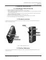
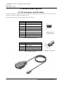
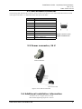
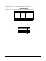
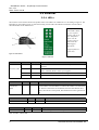
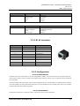
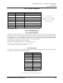
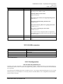
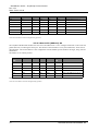
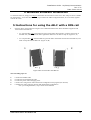
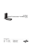
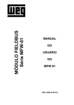
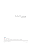
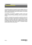
-Installation GuideAnyBus® Communicator Rev 1.40 DOC. ABC-IG Date: 2001-10-25 HMS INDUSTRIAL NETWORKS AB PHONE: +46 35 17 29 00 PIELEFELTSGATAN 93 - 95 FAX: +46 35 17 29 09 S - 302 50 HALMSTAD e-mail: [email protected] SWEDEN web: www.hms-networks.com -Installation Guide- AnyBus® Communicator Rev 1.31 Date: 2001-09-04 Table of Contents 1 General information . . . . . . . . . . . . . . . . . . . . . . . . . . . . . . . . . . . . . . . . . . . . . . . . . . . . . . . 2 1.1 Installation items check-list . . . . . . . . . . . . . . . . . . . . . . . . . . . . . . . . . . . . . . . . . . . . . . . . . . . . . . . . . . . . . 2 1.2 Product overview . . . . . . . . . . . . . . . . . . . . . . . . . . . . . . . . . . . . . . . . . . . . . . . . . . . . . . . . . . . . . . . . . . . . . 2 1.3 Further Reference . . . . . . . . . . . . . . . . . . . . . . . . . . . . . . . . . . . . . . . . . . . . . . . . . . . . . . . . . . . . . . . . . . . . . 2 2 General descriptions . . . . . . . . . . . . . . . . . . . . . . . . . . . . . . . . . . . . . . . . . . . . . . . . . . . . . . . 3 2.1 PC-connector and PC-cable . . . . . . . . . . . . . . . . . . . . . . . . . . . . . . . . . . . . . . . . . . . . . . . . . . . . . . . . . . . . . 2.2 Sub-network connector. . . . . . . . . . . . . . . . . . . . . . . . . . . . . . . . . . . . . . . . . . . . . . . . . . . . . . . . . . . . . . . . . 2.3 Power connector, 24 V . . . . . . . . . . . . . . . . . . . . . . . . . . . . . . . . . . . . . . . . . . . . . . . . . . . . . . . . . . . . . . . . . 2.4 Additional installation information . . . . . . . . . . . . . . . . . . . . . . . . . . . . . . . . . . . . . . . . . . . . . . . . . . . . . . . 3 4 4 4 3 Fieldbus specific descriptions. . . . . . . . . . . . . . . . . . . . . . . . . . . . . . . . . . . . . . . . . . . . . . . . 5 3.1 Profibus-DP . . . . . . . . . . . . . . . . . . . . . . . . . . . . . . . . . . . . . . . . . . . . . . . . . . . . . . . . . . . . . . . . . . . . . . . . . 5 3.1.1 LED’s. . . . . . . . . . . . . . . . . . . . . . . . . . . . . . . . . . . . . . . . . . . . . . . . . . . . . . . . . . . . . . . . . . . . . . . . . . 5 3.1.2 Profibus connector . . . . . . . . . . . . . . . . . . . . . . . . . . . . . . . . . . . . . . . . . . . . . . . . . . . . . . . . . . . . . . . . 6 3.1.3 Profibus configuration . . . . . . . . . . . . . . . . . . . . . . . . . . . . . . . . . . . . . . . . . . . . . . . . . . . . . . . . . . . . . 6 3.2 DeviceNet . . . . . . . . . . . . . . . . . . . . . . . . . . . . . . . . . . . . . . . . . . . . . . . . . . . . . . . . . . . . . . . . . . . . . . . . . . . 6 3.2.1 LED’s. . . . . . . . . . . . . . . . . . . . . . . . . . . . . . . . . . . . . . . . . . . . . . . . . . . . . . . . . . . . . . . . . . . . . . . . . . 6 3.2.2 DeviceNet connector . . . . . . . . . . . . . . . . . . . . . . . . . . . . . . . . . . . . . . . . . . . . . . . . . . . . . . . . . . . . . . 7 3.2.3 DeviceNet configuration . . . . . . . . . . . . . . . . . . . . . . . . . . . . . . . . . . . . . . . . . . . . . . . . . . . . . . . . . . . 7 3.2.3.1 Node address . . . . . . . . . . . . . . . . . . . . . . . . . . . . . . . . . . . . . . . . . . . . . . . . . . . . . . . . . . . . . . . . 8 3.2.3.2 Baudrate . . . . . . . . . . . . . . . . . . . . . . . . . . . . . . . . . . . . . . . . . . . . . . . . . . . . . . . . . . . . . . . . . . . 8 3.2.3.3 Termination . . . . . . . . . . . . . . . . . . . . . . . . . . . . . . . . . . . . . . . . . . . . . . . . . . . . . . . . . . . . . . . . . 8 3.3 Ethernet. . . . . . . . . . . . . . . . . . . . . . . . . . . . . . . . . . . . . . . . . . . . . . . . . . . . . . . . . . . . . . . . . . . . . . . . . . . . . 9 3.3.1 LED’s. . . . . . . . . . . . . . . . . . . . . . . . . . . . . . . . . . . . . . . . . . . . . . . . . . . . . . . . . . . . . . . . . . . . . . . . . . 9 3.3.2 RJ 45 connector . . . . . . . . . . . . . . . . . . . . . . . . . . . . . . . . . . . . . . . . . . . . . . . . . . . . . . . . . . . . . . . . . 10 3.3.3 Configuration . . . . . . . . . . . . . . . . . . . . . . . . . . . . . . . . . . . . . . . . . . . . . . . . . . . . . . . . . . . . . . . . . . . 10 3.3.3.1 Node address . . . . . . . . . . . . . . . . . . . . . . . . . . . . . . . . . . . . . . . . . . . . . . . . . . . . . . . . . . . . . . . 10 3.3.3.2 Termination . . . . . . . . . . . . . . . . . . . . . . . . . . . . . . . . . . . . . . . . . . . . . . . . . . . . . . . . . . . . . . . . 10 3.4 CANopen . . . . . . . . . . . . . . . . . . . . . . . . . . . . . . . . . . . . . . . . . . . . . . . . . . . . . . . . . . . . . . . . . . . . . . . . . . 11 3.4.1 LED’s. . . . . . . . . . . . . . . . . . . . . . . . . . . . . . . . . . . . . . . . . . . . . . . . . . . . . . . . . . . . . . . . . . . . . . . . . 11 3.4.2 D-SUB connector. . . . . . . . . . . . . . . . . . . . . . . . . . . . . . . . . . . . . . . . . . . . . . . . . . . . . . . . . . . . . . . . 12 3.4.3 Configuration . . . . . . . . . . . . . . . . . . . . . . . . . . . . . . . . . . . . . . . . . . . . . . . . . . . . . . . . . . . . . . . . . . . 12 3.4.3.1 Node address . . . . . . . . . . . . . . . . . . . . . . . . . . . . . . . . . . . . . . . . . . . . . . . . . . . . . . . . . . . . . . . 12 3.4.3.2 Baudrate . . . . . . . . . . . . . . . . . . . . . . . . . . . . . . . . . . . . . . . . . . . . . . . . . . . . . . . . . . . . . . . . . . 12 3.4.3.3 Termination . . . . . . . . . . . . . . . . . . . . . . . . . . . . . . . . . . . . . . . . . . . . . . . . . . . . . . . . . . . . . . . . 13 3.5 Modbus Plus . . . . . . . . . . . . . . . . . . . . . . . . . . . . . . . . . . . . . . . . . . . . . . . . . . . . . . . . . . . . . . . . . . . . . . . . 13 3.5.1 LED’s. . . . . . . . . . . . . . . . . . . . . . . . . . . . . . . . . . . . . . . . . . . . . . . . . . . . . . . . . . . . . . . . . . . . . . . . . 13 3.5.2 D-SUB connector. . . . . . . . . . . . . . . . . . . . . . . . . . . . . . . . . . . . . . . . . . . . . . . . . . . . . . . . . . . . . . . . 14 3.5.3 Configuration . . . . . . . . . . . . . . . . . . . . . . . . . . . . . . . . . . . . . . . . . . . . . . . . . . . . . . . . . . . . . . . . . . . 14 3.5.3.1 Node ID (Address) S1 . . . . . . . . . . . . . . . . . . . . . . . . . . . . . . . . . . . . . . . . . . . . . . . . . . . . . . . . 14 3.5.3.2 Source ID (Address) S2 . . . . . . . . . . . . . . . . . . . . . . . . . . . . . . . . . . . . . . . . . . . . . . . . . . . . . . 15 4 Windows software installation. . . . . . . . . . . . . . . . . . . . . . . . . . . . . . . . . . . . . . . . . . . . . . 16 5 Instructions for using the AB-C with a DIN-rail . . . . . . . . . . . . . . . . . . . . . . . . . . . . . . . 16 6 Technical specifications . . . . . . . . . . . . . . . . . . . . . . . . . . . . . . . . . . . . . . . . . . . . . . . . . . . 19 HMS INDUSTRIAL NETWORKS AB -Installation Guide- AnyBus® Communicator Rev 1.31 Date: 2001-09-04 1 General information 1.1 Installation items check-list • • • • • AnyBus Communicator (AB-C) part. no AB7000 AnyBus Communicator Configuration Pack, art no. 017620, including: * AB-C Configurator installation program (AbcCon) on the AB-C Resource CD (also available for download on www.hms-networks.com) * AB-C User Manual on the AB-C Resource CD (also available for download on www.hms-networks.com) * Cable for connecting a PC to the AB-C Fieldbus cable with connector for connecting a fieldbus to the AB-C Sub-network cable with DSUB9 male connector for connecting serial devices to the AB-C Power cable connected to a 24 V ± 10% power supply 1.2 Product overview The figure below illustrates the connectors and switches, situated on the AB-C. The AB-C illustrated in Figure 1 below is a Profibus-DP version. Figure 1: AnyBus Communicator overview 1.3 Further Reference Further information about the product is available in the AB-C User Manual and the fieldbus appendices on the AB-C Resource CD. HMS INDUSTRIAL NETWORKS AB 2 -Installation Guide- AnyBus® Communicator Rev 1.31 Date: 2001-09-04 2 General descriptions 2.1 PC-connector and PC-cable The AbcCon Windows Configurator Tool is used to configure and monitor the AB-C with a PC. Your PC can be connected to the AB-C PC-connector through a PC-cable. The following tables describe the pin configuration of the PC cable: Pin Description 1 Not connected 2 RS232 Rx, data input to PC 3 RS232 Tx, data output from PC 4 Not connected 5 Ground 6 Not connected 7 Not connected 8 Not connected 9 Not connected Female connector on the PC-cable Table 1: 9-pin DSUB pin description Pin Description 1 Signal ground 2 Signal ground 3 RS232 Rx, data input to AB-C 4 RS232 Tx, data output from AB-C Table 2: Modular 4/4 connector Modular 4/4 connector Figure 2: PC-cable 3 HMS INDUSTRIAL NETWORKS AB -Installation Guide- AnyBus® Communicator Rev 1.31 Date: 2001-09-04 2.2 Sub-network connector The following table describes the connector used to connect serial devices to the AB-C and all directions are stated with respect to the AB-C, i.e. RS232 Rx means data input to the AB-C. Pin Description 1 +5V 2 RS232 Rx 3 RS232 Tx 4 Not connected 5 Ground 6 RS422 Rx + 7 RS422 Rx - 8 RS485 + /RS422 Tx + 9 RS485 - /RS422 Tx - Female connector on the AnyBus Communicator Table 3: Sub-network connector pins 2.3 Power connector, 24 V + Power connector Figure 3: Power connector on the AB-C 2.4 Additional installation information •Use 60/75 or 75° C copper (CU) wire only •The terminal tightening torque of 5-7 lbs-in. HMS INDUSTRIAL NETWORKS AB 4 -Installation Guide- AnyBus® Communicator Rev 1.31 Date: 2001-09-04 3 Fieldbus specific descriptions 3.1 Profibus-DP 3.1.1 LED’s The 6 LED’s can be used to monitor the product status. The LED’s are numbered 1 to 6 according to Figure 4. The LED label on the product, Figure 5, states the meaning of each LED. The indication and status of each LED is described further in Table 4. Note: If the Device status LED is flashing in a sequence starting with one or more red flashes, please note the sequence pattern and contact the HMS support department. ([email protected]) Figure 4: LED numbers Figure 5: LED label LED Description Indication Status 1 Online Green Turned off Module is online Module is not online 2 Offline Red Turned off Module is offline Module is not offline 3 Not used 4 Fieldbus diagnostics Flashing red 1 Hz Flashing red 2 Hz Flashing red 4 Hz Turned off Error in configuration Error in user parameter data Error in initialisation No diagnostics present 5 Subnet status Off Flashing green Green Red Power off Not running Running Stopped 6 Device status Off Flashing red/green Green Flashing green Power off Configuration missing Initialising Running Table 4: Led descriptions 5 HMS INDUSTRIAL NETWORKS AB -Installation Guide- AnyBus® Communicator Rev 1.31 Date: 2001-09-04 3.1.2 Profibus connector Pin Name Function Housing Shield Connected to PE 1 Not connected - 2 Not connected - 3 B-Line Non-inverting RxD/TxD 4 RTS Request to send 5 GND BUS GND from RS485 6 +5 V BUS +5 V from RS485 7 Not connected - 8 A-Line Inverting RxD/TxD 9 Not connected - Female connector on the AnyBus Communicator Table 5: 9-pin DSUB connector 3.1.3 Profibus configuration The hatch on the side of the AB-C covers the configuration switches. A small screwdriver can be inserted at the top of the hatch in order to remove it. When removing the hatch, please be cautious. Do not touch the circuit boards and the components. The AB-C PDP module is equipped with two rotary switches for setting the node address. The address can be set within the range 1-99. The left switch (closest to the fieldbus connector) is the switch that sets the first of the two digits of the address (tens), whilst the right switch (closest to the LED:s), is used to set the second digit of the address (ones). 3.2 DeviceNet 3.2.1 LED’s The 6 LED’s can be used to monitor the product status. The LED’s are numbered 1 to 6 according to Figure 6. The LED label on the product, Figure 7, states the meaning of each LED. The indication and status of each LED is described further in Table 6. Note: If the Device status LED is flashing in a sequence starting with one or more red flashes, please note the sequence pattern and contact the HMS support department. ([email protected]) Figure 6: LED numbers Figure 7: LED label HMS INDUSTRIAL NETWORKS AB 6 -Installation Guide- AnyBus® Communicator Rev 1.31 Date: 2001-09-04 LED Description Indication Status 1 Network status Off Green Red Flashing green Flashing red Not powered / not online Link OK online, connected Critical link failure Online not connected Connection time-out 2 Module status Off Red Green Flashing red No power Unrecoverable fault Device operational Minor fault 3 Not used 4 Not used 5 Subnet status Off Flashing green Green Red Power off Not running Running Stopped 6 Device status Off Flashing red/green Green Flashing green Power off Configuration missing Initialising Running Table 6: DeviceNet LED’s 3.2.2 DeviceNet connector Pin Description 1 V- 2 CAN L 3 Shield 4 CAN H 5 V+ 5-pin plugable screw terminal Table 7: 5-pin plugable screw terminal on the AB-C DeviceNet module 3.2.3 DeviceNet configuration The hatch on the side of the AB-C covers the configuration switches. A small screwdriver can be inserted at the top of the hatch in order to remove it. When removing the hatch, please be cautious. Do not touch the circuit boards and the components. In a DeviceNet network, each node in the network has a Mac ID (the address in the network). The Mac ID is a number between 0 and 63. Each node's Mac ID has to be unique, since it is used to address the node. In a DeviceNet network it is also possible to configure the Baudrate, the following baud rates is possible to use in a network: 125, 250 and 500 kbit / sec. All nodes in the network have to communicate with the same baudrate. On the AB-C DeviceNet module, it is possible to set the Mac ID and the Baud rate with a physical DIP-switch. Dip 1 and 2 are used to configure the Baud rate and dips 3 to 8 are used to configure the node address (Mac ID). Dip 1 is the most significant bit on the dipswitch. 7 HMS INDUSTRIAL NETWORKS AB -Installation Guide- AnyBus® Communicator Rev 1.31 Date: 2001-09-04 When a switch is in the ‘ON’ or ‘Closed’ position, the modules interprets it as a logic ‘1’. 3.2.3.1 Node address Switches 3 to 8 are used to set the node address. Switch 3 is the MSB, and switch 8 is LSB. Address sw. 3 sw. 4 sw. 5 sw. 6 sw. 7 sw. 8 0 OFF OFF OFF OFF OFF OFF 1 OFF OFF OFF OFF OFF ON 2 OFF OFF OFF OFF ON OFF 3 OFF OFF OFF OFF ON ON ... ... ... ... ... ... ... 62 ON ON ON ON ON OFF 63 ON ON ON ON ON ON Table 8: Node address settings 3.2.3.2 Baudrate There are three different baudrates for DeviceNet; 125k, 250k, 500kbit/s. Choose one of them by setting dip switch 1 and 2 before configuring. Baud rate, bits/sec. sw. 1 sw. 2 125k OFF OFF 250k OFF ON 500k ON OFF Reserved ON ON Table 9: Baud rate settings 3.2.3.3 Termination DeviceNet uses termination resistors at each physical end of the bus. The termination resistor should be 121 ohm. This should be connected between CAN_H and CAN_L on the bus. HMS INDUSTRIAL NETWORKS AB 8 -Installation Guide- AnyBus® Communicator Rev 1.31 Date: 2001-09-04 3.3 Ethernet 3.3.1 LED’s The 6 LED’s can be used to monitor the product status. The LED’s are numbered 1 to 6 according to Figure 8. The LED label on the product, Figure 9, states the meaning of each LED. The indication and status of each LED is described further in the tables below. Note: If the Device status LED is flashing in a sequence starting with one or more red flashes, please note the sequence pattern and contact the HMS support department. ([email protected]) Figure 8: LED numbers Figure 9: LED label LED 1 Colour Frequency Description Green 1 Hz Indicates that the used IP address not is set by the values on the dipswitches. STATUS LED Red 1 Hz The Ethernet MAC address is not correct. The module will not be able to initialize. Please contact your supplier. Red 2 Hz The module failed to load Ethernet configuration from the FLASH. Red 4 Hz Internal error. Please contact your supplier. Table 10: LED 1 - Status LED LED 2 Colour Frequency Description Modbus/TCP Connection LED Green - Indicates the number of Modbus/TCP connections that are established to the module. The LED flashes to indicate the number of connections. Ex: If three connections are established, then this LED flashes three times, then off for a short period, then flashes three times again and so on. Table 11: LED 2 - Modbus/TCP connection LED LED 3 Colour Frequency Description LINK LED Green Steady on Indicates that the module is connected to an Ethernet network. Table 12: LED 3 - Link LED LED 4 Colour Frequency Description ACTIVITY LED Green - Flashes from green to off when a packet is received or transmitted. Table 13: LED 4 - Activity LED 9 HMS INDUSTRIAL NETWORKS AB -Installation Guide- AnyBus® Communicator Rev 1.31 Date: 2001-09-04 LED 5 Indication Description SUBNET STATUS LED Off Flashing green Green Red Power off Not running Running Stopped Table 14: LED 5 - Subnetwork Status LED 6 Indication Description DEVICE STATUS LED Off Flashing red/green Green Flashing green Power off Configuration missing Initialising Running Table 15: LED 6 - Device Status LED 3.3.2 RJ 45 connector Connector pin Signal Description 1 TD+ Positive Transmit Data 2 TD- Negative Transmit Data 3 RD+ Positive Receive Data 4 NC No connection 5 NC No connection 6 RD- Negative Receive Data 7 NC No connection 8 NC No connection Casing PE Protective earth Table 16: RJ45 Ethernet connector 3.3.3 Configuration 3.3.3.1 Node address The hatch on the side of the AB-C covers the configuration switches. A small screwdriver can be inserted at the top of the hatch in order to remove it. When removing the hatch, please be cautious. Do not touch the circuit boards and the components. The Ethernet MAC ID is permanent, and cannot be changed by the user. The IP-address is configured at the initialization of the module. For more information about how to set the IP-address for the module, please refer to the AnyBusS Ethernet/Modbus TCP fieldbus appendix. 3.3.3.2 Termination The Ethernet module uses twisted-pair cables, and do not need an external terminator. HMS INDUSTRIAL NETWORKS AB 10 -Installation Guide- AnyBus® Communicator Rev 1.31 Date: 2001-09-04 3.4 CANopen 3.4.1 LED’s The 6 LED’s can be used to monitor the product status. The LED’s are numbered 1 to 6 according to Figure 10. The LED label on the product, Figure 11, states the meaning of each LED. The indication and status of each LED is described further in the tables below. Note: If the Device status LED is flashing in a sequence starting with one or more red flashes, please note the sequence pattern and contact the HMS support department. ([email protected]) Figure 10: LED numbers Figure 11: LED label LED number 3 is not used on the AB-C CANopen module. LED 1 STATE INDICATION Colour Frequency Description Green 1 Hz Module in ‘Pre-Operational’ state Green 2 Hz Module in ‘Prepared’ state Green Steady on Module in ‘Operational state’ Red 1 Hz Bus initialisation failed Table 17: LED 1 - State indication LED 2 BUS INDICATION Colour Frequency Description Green 1 Hz Bus off / error passive Green Steady on Bus running Red 1 Hz Other error Off - Power off or module not initialised Table 18: LED 2 - Bus indication LED 4 Colour Frequency Description POWER Green Steady on Module has power Table 19: LED 4 - Power 11 HMS INDUSTRIAL NETWORKS AB -Installation Guide- AnyBus® Communicator Rev 1.31 Date: 2001-09-04 3.4.2 D-SUB connector Connector pin Signal Description 1 - Reserved 2 CAN_L CAN_L Bus line (dominant low) 3 CAN_GND CAN ground 4 - Reserved 5 CAN_SHLD Optional CAN Shield 6 GND Optional ground 7 CAN_H CAN_H Bus line (dominant high) 8 - Reserved 9 CAN_V+ Optional CAN external power supply Table 20: D-SUB connector 3.4.3 Configuration 3.4.3.1 Node address The hatch on the side of the AB-C covers the configuration switches. A small screwdriver can be inserted at the top of the hatch in order to remove it. When removing the hatch, please be cautious. Do not touch the circuit boards and the components. The network node address is set with two rotary switches on the option board (ADDRESS_HIGH and ADDRESS_LOW), or with the ‘FIELDBUS_SPECIFIC_INIT’ telegram during startup of the module. Possible node address if you use the dip switches are between 1 - 99 in decimal format. The node address is calculated in the following way: Node address = (ADDRESS_HIGH * 10) + (ADDRESS_LOW * 1) Note: Pdo 3 - 8 only have default cobid's if the node address is less than 64. Note: The node address cannot be changed during operation. 3.4.3.2 Baudrate The baudrate is configured with one decimal rotary switch, or with the ‘FIELDBUS_SPECIFIC_INIT’ telegram during start-up. See table below for supported baudrates. Switch setting Baudrate 0 Not available 1 10 kbit/s 2 20 kbit/s 3 50 kbit/s 4 125 kbit/s 5 250 kbit/s 6 500 kbit/s 7 800 kbit/s 8 1 Mbit/s 9 Not available Table 21: Baudrate switch settings Note: The baudrate can not be changed during operation HMS INDUSTRIAL NETWORKS AB 12 -Installation Guide- AnyBus® Communicator Rev 1.31 Date: 2001-09-04 3.4.3.3 Termination CANopen uses standard CAN termination on the first and last node on the network. The termination resistor should be 120 ohm. This should be connected between CAN_H and CAN_L on the bus. Note that the termination is only used when the AnyBus-S module is the first or last node on the bus. 3.5 Modbus Plus 3.5.1 LED’s The 6 LED’s can be used to monitor the product status. The LED’s are numbered 1 to 6 according to Figure 12. The LED label on the product, Figure 13, states the meaning of each LED. The indication and status of each LED is described further in the tables below. Note: If the Device status LED is flashing in a sequence starting with one or more red flashes, please note the sequence pattern and contact the HMS support department. ([email protected]) Figure 12: LED numbers Figure 13: LED label The AnyBus-C Modbus Plus module has two fieldbus specific and two standard (stacked) indication LED’s. The functionality of these LED’s is described below: LED no. Indication Description 1 Active Red ERROR; This LED is indicating that the communication is not OK. Table 22: AB-C Modbus Plus LED’s 13 HMS INDUSTRIAL NETWORKS AB -Installation Guide- AnyBus® Communicator Rev 1.31 Date: 2001-09-04 LED no. Indication Description 2 Green MBP Active; This diagnostic flashes in different patterns depending on the modules’ health. Indicating different Node Status: Flash every 160 ms This node works normal, receiving and passing token: Flash every 1 s This node is in MONITOR_OFFLINE state: 2 flashes, off 2 s This node is in MAC_IDLE never-getting-token state: 3 flashes, off 1.7 s This node is not hearing any other nodes: 4 flashes, off 1.4 s This node has heard a valid packet that has a duplicatednode-address sent from another node on the network, using the same Node ID. 3 - Not Used 4 Active solid green MBP Init; This LED indicating if the peer interface is initialised. Table 22: AB-C Modbus Plus LED’s 3.5.2 D-SUB connector D-SUB Name 1 Cable Shielding 2 MBP Line B 3 MBP Line A Housing PE Table 23: D-SUB connector 3.5.3 Configuration 3.5.3.1 Node ID (Address) S1 The hatch on the side of the AB-C covers the configuration switches. A small screwdriver can be inserted at the top of the hatch in order to remove it. When removing the hatch, please be cautious. Do not touch the circuit boards and the components. The Node ID on the Modbus Plus node is set before power on. Any change of Node ID during power on is not valid until next power cycle. The address is set in binary format. The Node address is also configurable with the fieldbus specific mailbox messages. HMS INDUSTRIAL NETWORKS AB 14 -Installation Guide- AnyBus® Communicator Rev 1.31 Date: 2001-09-04 1 MSB 2 3 4 5 6 LSB Function ON ON ON ON ON ON Node address set to 1 ON ON ON ON ON OFF Node address set to 2 ON ON ON ON OFF ON Node address set to 3 - - - - OFF OFF OFF OFF OFF ON Node address set to 63 OFF OFF OFF OFF OFF OFF Node address set to 64 Table 24: Switch settings for Node ID Note: The node address cannot be changed during operation. 3.5.3.2 Source ID (Address) S2 The AnyBus-S Modbus Plus module uses one source ID address from 1 -64 to configure what node it will extract the global data from, sent during the token pass. The amount of extracted data is set by the initialisation, which will be described later. The Source address is also configurable with the fieldbus specific mailbox messages, along with the GDB offset. The address is set in binary format. 1 MSB 2 3 4 5 6 LSB Function ON ON ON ON ON ON Source ID address set to 1 ON ON ON ON ON OFF Source ID address set to 2 ON ON ON ON OFF ON Source ID address set to 3 - - - - OFF OFF OFF OFF OFF ON Source ID address set to 63 OFF OFF OFF OFF OFF OFF Source ID address set to 64 Table 25: Switch settings for Source ID Note: The source address cannot be changed during operation. 15 HMS INDUSTRIAL NETWORKS AB -Installation Guide- AnyBus® Communicator Rev 1.31 Date: 2001-09-04 4 Windows software installation To install the AbcCon, simply run setup.exe and follow the instructions on the screen. The setup.exe file is available for download on: www.hms-networks.com, or provided in the ABC Configuration Pack, art. no 017620, together with the PC cable. 5 Instructions for using the AB-C with a DIN-rail 1. Snap the AB-C on the DIN-rail. In figure 10 it is demonstrated how the AB-C should be snapped on and removed from the DIN-rail. * To “snap the AB-C on” to the DIN-rail, first press the AB-C downwards to compress the spring on the DIN- rail, and then push the AB-C against the DIN-rail as to make it snap on. (Figure 14; A) * To “snap the AB-C off” from the DIN-rail, push the AB-C downwards and out from the DIN-rail, as to make it snap off from the DIN-rail. (Figure 14; B) Figure 14: How to use the AB-C with a DIN-rail The succeeding steps are: 2. 3. 4. 5. 6. Connect the fieldbus cable Connect the serial subnetwork cable Connect the power cable and apply power Connect a PC using the PC cable and start the configuration tool program (the AbcCon) Configure the AB-C using the AbcCon and download the configuration For a pre-configured AB-C, steps 5 and 6 can be omitted HMS INDUSTRIAL NETWORKS AB 16 -Installation Guide- AnyBus® Communicator Rev 1.31 Date: 2001-09-04 This page is intentionally left blank. 17 HMS INDUSTRIAL NETWORKS AB -Installation Guide- AnyBus® Communicator Rev 1.31 Date: 2001-09-04 This page is intentionally left blank. HMS INDUSTRIAL NETWORKS AB 18 -Installation Guide- AnyBus® Communicator Rev 1.31 Date: 2001-09-04 6 Technical specifications Operating temperature: +5°C to 55°C. Humidity: -5 to 95% non-condensing. Dimensions: 120 mm x 75 mm x 27 mm (L x W x H) Power supply: Power: 24V±10%. Maximum power consumption is 280 mA on 24V. Typically around 100 mA. Mechanical: Plastic housing with snap-on connection to DIN-rail. UL: This unit is open type listed by the Underwriters Laboratories, UL. The certificate is valid when the unit is installed in a switch cabinet or equivalent. The certification has been documented by UL in file E 214107. CE-mark: Certified according to European standards unless otherwise is stated. Emission: According to EN 50081-2:1993 Immunity: According to EN 61000-6-2:1999 EMC: System requirements for the Configurator software: Pentium 133 MHz or higher 10 MB free space on hard drive 8 MB RAM Win95/98/NT/2000/ME Internet Explorer 4.01 SP1. HMS Industrial Networks AB assumes no responsibility for any errors that may appear in this document. The information in this manual is subject to change without notice and should not be considered as a commitment by HMS Industrial Networks AB. The product warranty is valid if the instructions in this Installation Guide and the User Manual are followed correctly. ANYBUS is a registered trademark of HMS Industrial Networks AB. All other trademarks are the property of their respective holders. For more information about the AnyBus Communicator please refer to the AnyBus Communicator User Manual. For support visit the HMS website www.hms-networks.com, or contact: Europe (Sweden) Germany Phone: +46 (0)35 - 17 29 22 e-mail: [email protected] Phone: +49-721-96472 0 e-mail: [email protected] Japan North America Phone +81-45-478-5340 e-mail: [email protected] Phone: +1-773-404-2271 Toll-free number: 888-8-ANYBUS e-mail: [email protected] 19 HMS INDUSTRIAL NETWORKS AB