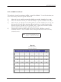
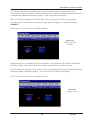
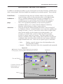
1
perfectHOST
User Manual
www..richards-zeta.com
perfectHOST User Manual
Copyright 2003
Richards-Zeta Building Intelligence, Inc.
All Rights Reserved
The confidential information contained in this manual is provided solely for use by employees of
Richards-Zeta, licensees, authorized distributors, and system owners; and it is not to be released
to, or reproduced for anyone else. This information is also not to be used for the reproduction of
this control system or any of its components.
All rights to revise designs herein described are reserved. All products and specifications are
subject to change without notice.
Windows95 and MS-DOS are trademarks of Microsoft Corporation.
While every effort has been made to ensure the accuracy of this material, Richards-Zeta shall not
be held responsible for damages — including consequential damages — arising from the application
of the information contained herein.
perfectHOST:
TABLE OF CONTENTS
GETTING STARTED ....................................................................................................................................... 3
Hardware Requirements ............................................................................................................................................. 3
Installing perfectHOST for Windows ....................................................................................................................... 4
Connecting to PHWIN When Booting Up Windows95 ....................................................................................... 5
Graphical Programming .............................................................................................................................................. 6
Starting perfectHOST for Windows ......................................................................................................................... 7
APPLICATION EDITOR ............................................................................................................................... 16
FILE Menu ..................................................................................................................................................................... 17
EDIT Menu ................................................................................................................................................................... 27
DRAWING Menu ....................................................................................................................................................... 33
ADD Menu ................................................................................................................................................................... 44
SYSTEM Menu ............................................................................................................................................................. 49
SETTINGS Menu ......................................................................................................................................................... 64
APPLICATION EXAMPLE ............................................................................................................................ 66
Naming Templates ...................................................................................................................................................... 66
Sequence of Programming ....................................................................................................................................... 68
Programming Example ............................................................................................................................................... 68
Reference Trimmers .................................................................................................................................................. 71
Connecting Templates ............................................................................................................................................... 72
Input Template Offsets .............................................................................................................................................. 73
Scaling Output Templates ......................................................................................................................................... 74
Logic Programming .................................................................................................................................................... 75
SCHEDULES ................................................................................................................................................. 93
Creating a Drawing..................................................................................................................................................... 93
Connecting Templates ............................................................................................................................................... 96
Timeclock Schedules ................................................................................................................................................. 97
Copying a Daily Schedule ......................................................................................................................................... 98
Override Schedules ................................................................................................................................................... 99
Other Time Schedule Information ........................................................................................................................ 101
ALARMS ...................................................................................................................................................... 102
Adding a Monitoring Alarm to a Drawing........................................................................................................... 102
Monitoring Alarms ................................................................................................................................................... 106
Printing and Acknowledging Alarm Logs ............................................................................................................ 106
Removing Alarm Logs ............................................................................................................................................. 107
MONITOR DRAWING EDITOR .............................................................................................................. 108
.pax Drawings/.pix Drawings .................................................................................................................................. 108
Additional Graphical Elements ............................................................................................................................... 109
Virtual Points .............................................................................................................................................................. 112
perfectHOST Manual
perfectHost:
GETTING STARTED
Hardware Requirements
Minimum Recommended System:
• IBM-PC 486DX33 or higher
• 640k standard RAM
• 8 MB extended memory
• VGA or SVGA monitor
• Logitech or Microsoft-compatible mouse
• 80 MB hard disk
• 5 1/4" or 3 ½” HD floppy drive
• Two serial, one parallel port
• MS-DOS Version 6.0 or later
• Microsoft Windows Version 3.1 or later
Note: If multiple applications are to be run on the same system, additional hard disk and RAM
space is desirable. In general, computers with faster clock speeds (MHZ) will provide
faster response times. A math coprocessor chip and video accelerator card
(2-4 Mb RAM), while optional, will also tend to improve system performance.
4
Getting Started
perfectHOST Manual
INSTALLING perfectHOST
To install perfectHOSTtm from disk:
Windows 3.1
FLOPPY DISK INSTALL
Choose "Run" from the File menu. Then type:
a:\setup <return>
CD-ROM INSTALL
Choose "Run" from theFile menu. Then type:
d:\phwin\disk1\setup
Windows 95
FLOPPY DISK INSTALL
Click on START and then RUN. In the RUN dialog box type:
a:\setup <return>
CD-ROM INSTALL
Click on START and the RUN. IN the RUN dialog box type:
d:\phwin\disk1\setup
The installation starts. The program files have been compressed; as perfectHOST for Windows
is installed, the files are copied onto your computer’s hard drive and uncompressed. The
screen will prompt you through the installation procedure.
2. Insert Disk 2 when prompted.
3. Insert Disk 3 when prompted.
4. Insert Disk 4 when prompted.
Note: Number of disks may vary
depending on version.
When the installation is complete, the message “Installation Complete” will pop up on the
screen. The icon below is an example of the perfectHOST for Windows icon that appears
once the program is installed:
Note: perfectHOSTtm software comes equipped with a software lock to prevent
unauthorized use of the program. The program will not run unless the software
key is in place. To install the key, simply plug it into the parallel port on your
computer. This must be the first parallel port (usually referred to as LPT1). If you
do not have a parallel port and/or the key is not in place, the software will not
run. You may make back up copies of your system disks, and it is recommended
that you do so. The system diskettes are not copy-protected. However, your
system software is subject to the license agreement that came with the software.
Please read the license agreement carefully and make sure that you agree with its
terms before installing the software. Installation of the software is an implicit
agreement to these terms. Consult the license agreement for more information.
5
Getting Started
perfectHOST Manual
CONNECTING TO PHWIN WHEN BOOTING UP WINDOWS95
The following instructions explain how to set up Windows95 so that perfectHOST for Windows
(PHWIN) will launch automatically when Windows95 is started.
1.
Open the Windows95 Startup group by placing your cursor over the “Start” button
and then clicking the right mouse button. Select Open. You should then see the
Startup Group looking like the following window:
Figure 1.
Windows95 Startup
Group
2.
Figure 2.
Creating a Shortcut in
Windows95
Click on File, New, Shortcut.
Then, at the “Command Line”
prompt, type
C:\phwin\phwin.exe.
Click on Next and Finish.
The PHWIN Startup icon will
be created and will launch
the program during
computer startup.
6
Getting Started
perfectHOST Manual
GRAPHICAL PROGRAMMING
R
ichards-Zeta’s perfectHOST for Windows offers an entirely new approach to entering
application data and program information into a building automation system.
perfectHOST for Windows creates the application program for Building Intelligence hardware
by using pictorial icons.
These pictorial icons are created through a technique called graphical programming. You will
create a schematic drawing of the control system on your computer screen using templates.
The control scheme is drawn and control flows through the drawing from inputs, through
processing logic, to outputs.
When the drawing is complete, perfectHOSTconverts it into a computer program that is downloaded to the Building Intelligence hardware. There are no programming languages to learn
and no programming limitations due to “canned” routines — the perfectHOST for Windows
system is fully programmable. Programming time is greatly reduced. If you can imagine what
you want the system to do, it can be done.
Templates
Templates are graphical symbols that represent part of the program code. Each template
performs some portion of the control logic. When several templates are connected together,
they become a complete program.
Figure 3. The “And” Template
Templates can represent simple control logic such as the “And” template shown in Figure 3
above, or they can represent more complex operations, such as the “Counter” template in
Figure 4 below.
Figure 4. The “Counter” Template
perfectHOST for Windows has a full library of templates available. This library is accessed by
pulling down the Add menu in the Application Editor and selecting Template. We will walk
through the process of selecting and adding a template when we construct a drawing later in
this manual.
7
Getting Started
perfectHOST Manual
STARTING perfectHOST
From the Windows Program Manager window, double-click on the perfectHOST icon with the
left mouse button. The perfectHOST screen appears with the Transcript
window open.
Figure 5.
The perfectHOST Main
Screen
The perfectHOST program is a menu-driven system. Most functions can be accessed through
the pull-down menus associated with each window. Click once on File in the menu bar to
access the File Menu as shown in Figure 6 below:
Figure 6.
The File Menu in the
perfectHOST Main Screen
The choices here represent the major operating sections of the application programming
environment. Before we learn how to program an application, we’ll briefly review each menu
item and its submenus.
8
Getting Started
perfectHOST Manual
MAIN SCREEN: FILE SUBMENUS
Print
This selection will bring up the Print window, which will allow you to select a printer and its
settings, and then print the data in the Transcript window. The Transcript window is the first
window that appears when you open perfectHOST. For more details, see the “Transcript
Window” section of this manual.
Application Editor
This selection opens the Programming Editor, which will allow you to create the programs
for your specific application. Your mind and your imagination are your only limits with
perfectHOST.
Template Editor
This selection will allow you to review, create, and edit templates. Templates are the primary
building blocks used in perfectHOST Graphical Programming. Each template is a pictorial
representation of a logical subroutine. These subroutines reside inside of the picture. Inputs
and outputs of the logic are “tagged” to the associated picture to allow logic flow from one
pictorial template to another. A collection of templates connected in a flowchart format
comprise a sequence of operations in one or more controllers on a network.
Figure 7.
perfectHOST
Template Editor
9
Getting Started
perfectHOST Manual
Macro Template Editor
This selection will allow you to review, create, and edit macro templates. A macro template is a
pictorial representation of a group of templates arranged to execute a logic sequence. Macros
serve to completely eliminate the need to learn a programming language. Simply stated —
a macro is a picture within a picture. This programming tool is often used when a particular
control strategy is needed over and over, or when a particular unit is encountered in many
different job sites.
Macros eliminate some of the detail from control drawings and allow easy duplication of
complex strategies with the placement of one picture. They can reduce the number of control
drawings, eliminate complexity, and speed overall system design. While a control drawing
constructed from standard templates shows every detail of the control structure, a control
drawing constructed with macro templates does not show all details. There is no difference
in system control whether or not macro templates are used; it is possible to create templates
with the same functionality of macros. Macros exist primarily for the convenience of
the programmer.
Figure 8.
The Macro Editor for
perfectHOST
10
Getting Started
perfectHOST Manual
Monitor Window
This selection will access a specific application for the purpose of monitoring that application.
The Monitor window includes useful functions such as screen jumps, animations, pushbuttons,
Timeclock Editor, point override, color fills, moving bar, alarm notification, etc.
Monitor Drawing Editor
This selection will allow you to edit your monitor drawings for an application you have created.
This editor includes drawing tools and many special functions used to enhance the user
environment.
Animation Editor
This selection will allow you to create and edit animations used for customizing monitor drawings. Animations can be static or dynamic. A static animation will select a view based on a
numeric value (i.e., 0 = view1, 1 = view2, 2 = view3, etc.) A dynamic animation continually
cycles through its views when the command value is greater than 0, and presents a default
view when the command value is 0 (i.e., a rotating fan symbol).
Figure 9.
perfectHOST
Animation Editor
11
Getting Started
perfectHOST Manual
Alarm Log Browser
This selection will allow you to view a history of alarm events that have been stored on your
hard disk. Later in this manual we’ll explain how to set up alarms.
Trend Log Browser
This selection will allow you to view any trend logs that have been stored on the hard disk.
Trends can be set up to record any information you would like at any time interval you desire.
These trends are stored in the trend log to be viewed and or printed at a later time.
Utilities
This selection wil allow you to set up passwords with different levels of access to the program,
from monitoring the system to full programming. There is a selection to Archive an application,
in which perfectHOST will take a selected application and condense it to a smaller file size to
be stored for later use. There is also a selection to Extract an application, in which the condensed application is opened up again for your use.
Figure 10.
Archive Application
for perfectHOST
Figure 11.
Extract Application
from Archive for
perfectHOST
12
Getting Started
perfectHOST Manual
Password Editor
This selection will allow you to set up a user name and a password, with eight different access
levels. The user name and password are case-sensitive, so be careful when you set up your
passwords. If for some reason you cannot access perfectHOST because of problems with your
passwords, contact Richards-Zeta to repair the problem.
Figure 12.
Password Editor for
perfectHOST
There are eight access levels available with this system, the lowest being Monitoring and the
highest being Maximum.
1) Monitoring
This only allows the user to observe the drawing that is on the
screen in the Monitor window.
2) Pushbuttons
This allows the user to select any pushbuttons on that one screen.
3) Schedules
This allows the user to edit time schedules and
the functions above.
4) Overrides
This allows the user to specify overrides to
any templates on that same screen and
everything above.
5) Select
This allows the user to move between all
Monitor Drawings and everything above.
Figure 13.
Access Levels for
perfectHOST
6) Monitor Editor This allows the user to use the Monitor
Editor and everything above.
13
Getting Started
perfectHOST Manual
Password Editor, continued
7) Application
This allows the user access to all program functions except for the
Password Editor.
8) Maximum
This allows the user complete access to the program including the
Password Editor.
About perfectHOST
This selection shows the version of perfectHOST currently in use, along with the address,
phone number, and website address for Richards-Zeta.
Figure 14.
About
perfectHOST
14
Getting Started
perfectHOST Manual
Application Editor Shortcuts/Hot Keys
File Menu
SAVE APPLICATION: (CTRL+S)
SAVE AS...: (CTRL+SHIFT+S)
PRINT APPLICATION: (ALT+P)
UPDATE TEMPLATES: (ALT+SHIFT+U)
TREND LOG EDITOR: (ALT+L)
ALARM EDITOR: (ALT+A)
I\O POINT EDITOR: (ALT+U)
TIME SCHEDULE EDITOR: (ALT+E)
Edit Menu
CUT : (CTRL+X)
COPY: (CTRL+C)
PASTE: (CTRL+V)
RENAME: (CTRL+A)
CUT DRAWING: (CTRL+SHIFT+X)
COPY DRAWING: (CTRL+SHIFT+C)
PASTE DRAWING: (CTRL+SHIFT+V)
EDIT ELEMENT: (CTRL+E)
Drawing Menu
SELECT DRAWING: (CRTL+D)
PREVIOUS DRAWING: (ALT+P)
NEW DRAWING: (ALT+SHIFT+N)
RENAME DRAWING: (CTRL+SHIFT+N)
FIND REFERENCES TO SELECTED TEMPLATES: (CTRL+F)
FIND REFERENCE TO NAME: (CTRL+SHIFT+F)
ASSIGN DRAWING TO UNIT: (CTRL+U)
MAKE MONITOR DRAWINGS: (ALT+M)
EDIT DRAWING DESCRIPTION: (ALT+W)
DISPLAY GRID: (ALT+G)
DISPLAY NETWORK ASSIGNMENTS: (ALT+K)
DISPLAY ALL TEMPLATE NAMES: (ALT+I)
DISPLAY UNCONNECTED INPUTS: (ALT+O)
REDRAW SCREEN: (CTRL+R)
15
Application Editor
perfectHOST Manual
Application Editor Shortcuts/Hot Keys, continued
Add Menu
CONNECT: (ALT+C)
TEMPLATE: (ALT+T)
REFERENCE: (ALT+R)
NUMBER: (ALT+N)
TEXT: (ALT+X)
System Menu
COMPILE: (CTRL+ALT+C)
TRANSCRIPT WINDOW:
COMM SETTINGS: (ALT+SHIFT+S)
MODEM SETTINGS:
DOWNLOAD WINDOW: (ALT+D)
MERGE APPLICATIONS: (CTRL+ALT+M)
PASSWORD: (CTRL+P)
HANDHELD SUPPORT: (CTRL+H)
16
Application Editor
perfectHOST Manual
APPLICATION EDITOR
Now we are ready to begin programming:
Pull down the File menu and select Application Editor. The Select Application window
will appear:
Figure 15.
Select Application
Window
This window allows you to select a previous system with which to work (if any have been
created) or to create an entirely new system.
When New is selected, perfectHOST will ask you to enter your job name:
Figure 16.
Enter Job Name
For purposes of this manual, we’ll call this JOB1. Type in JOB1at the cursor and click OK.
The Application Editor will open for JOB1.
Hint:
When you create a new application, you may find that the Application menu bar items
appear shaded (not active). If this occurs, from the File menu choose “Save Application,”
then close the application and reopen it. At this point all menu items should be active.
17
Application Editor
perfectHOST Manual
Now we’ll review all menu items related to the Application Editor before we start
programming.
FILE MENU
Figure 17.
Application Editor
for perfectHOST
Hint:
These key combinations are “hot keys” that
allow you to make the same selection
without having to make menu selections
with the mouse.
SAVE APPLICATION (CTRL+S)
This selection is typical of any Windows program. By selecting Save, the program will save the
application at the point you initiate this function, using the name under which the program was
opened. EXAMPLE: If opened as JOB1, it will be saved as JOB1 in a subdirectory named
c:\PHWIN\APPLICAT\JOB1.
SAVE AS (CTRL+SHIFT+S)
Again, this selection is typical of any Windows program. By selecting Save As, the program will
prompt you for a new name. Saved in this manner, the original file is not replaced. In fact, a
new subirectory is created using the new name that you enter. Use the Save As command if
you would like to test changes before erasing the original program. For example, you can Save
As JOB2 and if you later discover that the changes don't work, you can reload the old program
still on disk as JOB1.
Hint:
When you use the Save command, a file named drawing.bak is created in your application directory.
This file is a copy of the previously saved application. A last-resort method of recovering an
application prior to changes is to delete drawing.obj and rename drawing.bak to drawing.obj.
18
Application Editor
perfectHOST Manual
PRINT APPLICATION (ALT+P)
This selection will prompt you to select Entire Application, All Drawings, or any one drawing
you wish to print.
Entire Application:
This function will print all drawings, drawing descriptions, templates, and
macros used in your program. A hard copy of the program can be very
useful for training and troubleshooting. With this printed information, the
handheld interface can be used rather than a laptop computer to run and
monitor a system.
All Drawings:
This function will print the drawings only — without descriptions,
templates, and macros.
Drawing Selection:
• Single Drawing • Range -
Click on a drawing name to highlight it and then OK.
Click on a drawing name and then another while holding
down the “Shift” key. All drawings between the two
selected will be printed.
• Multiple Random - Click on a drawing name and then another while holding
down the “Ctrl” key. Repeat this as many times as needed.
UPDATE TEMPLATES (ALT+SHIFT+U)
This selection will compare the program templates in template.obj to those in
c:\phwin\template and c:\phwin\macros. If perfectHOST sees newer templates with the same
name in c:\phwin\template or c:\phwin\macros than in the template.obj file (located in your
application subdirectory) you will be given the option to update the templates stored in
template.obj. This is done on an individual template basis. This option is helpful when you
have an old application running somewhere and you want the latest templates for that application. If you don’t want these updates, click Disable Saving in the Update Templates box.
Figure 18.
Update
Templates
Hint: You can
use the "Ctrl"
and "Shift" keys
as described
above to select
a range or
random group
of templates to
update.
19
Application Editor
perfectHOST Manual
ARCHIVE TEMPLATES: TEMPLATE.OBJ updates PHWIN
This selection will look to the file template.obj, which is stored in each application’s
subdirectory. If you do not have this file, you might consider updating your version of PHWIN,
or save the application if you have not done this since updating. If the program sees that
there are new or changed templates in this template.obj file, it will ask you if you would like to
update these files (save them to disk in c:\phwin\macros or c:\phwin\template). This is done
on an individual template basis. This feature is useful if you receive an application from someone else and they have made new templates or changed a template in some way. This
function gives you the ability to update or add to your template libraries on disk in the
c:\phwin\template and c:\phwin\macros subdirectories. If you open Template or Macro
Editor by double-clicking on the template image while you are working in an application, and
the program sees that a template is different or new, it will automatically update your template
file for that specific template.
Figure 19.
Save Templates
to Disk
20
Application Editor
perfectHOST Manual
TREND LOG EDITOR (ALT+L)
NOTE: The function options listed in the
“Host Actions” section of this editor apply
to the HOST PC ONLY.
This selection will allow you to edit exactly how a trend is handled when the host computer
receives the trend from the controller. The first selection should be the trend name. These
names are created when you name a Trend template in the Application Editor. The Port should
be selected next. The Port selection refers to the auxiliary communications port (comm2) on
an RZ controller. RZ 1000 and moZaic boards have these ports built onto the board. RZ 100
controllers require the addition of a “Comm232” card to utilize this port. It is very important
that this Port selection matches the controller to which you have physically connected your
printer, modem, host computer, or other serial device. If you select your trends to report to an
RZ board that does not have a comm port, the trends will not function properly.
HOST Actions:
Log to disk only –
Print –
Merge –
Print/merge –
The system will only save the trend to the disk.
Save to disk and print out as received.
Save to disk and merge data to previous log.
Save to disk and merge data and print data.
If you are using a modem to send your trend to a remote site, it will also be necessary to set
the phone number. You will need to type atdt (attention[at], dialtone[dt]) before any phone
number used with perfectHOST.
Example:
atdt 424-3225
Figure 20.
Trend Log
Message Editor
21
Application Editor
perfectHOST Manual
FORMATTING TREND DATA
The default formatting for trendlog data works well. If you need to customize the formatting,
use the method detailed below:
If the keyword Format: is found in the text message for the trendlog, the next line will be interpreted according to
the following scheme:
Format:
%YMD %10.2 %8.3 %12.6 etc.
Each format specification must be preceded by a % character and separated from each other by one or more
spaces. The first specifier is for the date. The available formats are:
Specifier
%YMD
%MDY
%DMY
%TXT
Format
960201
020196
010296
Feb 1, 1996
The numeric specifiers which follow the date specifier apply to each column of numbers in the order they appear
in the line. If there are more columns than format specifiers, then the last specifier in the line is used for each
additional column. The specifier is interpreted as fieldWidth.precision. The fieldWidth is the total width of the
column including the decimal point and any spaces required for readability. The precision is the number of digits
following the decimal point. Trailing zeros (0) are padded on the right to ensure that the column decimal points
line up. If the number is longer than the fieldWidth, it will be lengthened to display the entire number.
Note:
Using the formatting commands in the Trend Editor may cause the graphing function
in the Trendlog Browser to not function (check ver.#). If you are using Excel or another
DDE-compliant program for graphing functions, this is not a concern. Otherwise, you may
want to use standard formatting.
ALARM EDITOR (ALT+A)
This selection will allow you to define how an alarm is handled when it is received by the host
computer or dedicated alarm printer from the controller. This subject is discussed in detail in
the section covering Alarms.
Figure 21.
Alarm Message
Editor
Hint: The Alarm Message Editor can be
invoked from the menu selection or
you can double-click on the Alarm
template. This is true of all special
editors.
22
Application Editor
perfectHOST Manual
I/O POINT EDITOR (ALT+U)
This selection is used to assign inputs and outputs to the proper controller or add-on board.
Depending on the board type, these points may be:
AI
Analog input
DI
Digital input (dry contact or pulse counter)
AO Analog output (fixed voltage or pwm output)
DO Digital output
HOA Hand/off/auto feedback (available with add-on boards and KC4401)
After placing templates in an application, you will need to assign all the points you used in your
system to specific control boards and to specific locations (I/O) on those boards.
1)
2)
3)
4)
5)
Open the I/O Editor and select Create New Controller.
Enter the name you wish to call this controller. You can label it as a number of an air
handler, building, or chiller number (anything you wish), but usually it is helpful to name
it for something involved with the system. Limit your name to eight characters (follow
traditional 8.3 DOS rules when creating this name).
After the name is entered, you’ll be prompted to enter the LAN address of the
RZ board that will be running this application. Enter it and select OK. If you do not yet
know the board number, you can enter any temporary number.
If you are using an RZ 100 with add-on boards, you will now need to assign these
boards to that RZ 100. It is important to remember that you must list the add-on
boards in the same order as they are connected physically to the board. If this is
not done, none of the boards will function properly.
Select Add Expansion I/O — a list will pop up with the different types of boards
available. Click on the proper one and it will be listed under the RZ 100 board.
At the same time, you will notice that more points will be added to the I/O Points
column.
(continued on next page)
Figure 21a.
I/O Editor
23
Application Editor
perfectHOST Manual
I/O EDITOR, continued
4)
Next, select the Board Type. There are currently four choices:
1) KC 4401
2) RZ 1000
3) RZ 100
4) moZaic
5)
Select the Protocol. Under normal conditions you will select Host. If you are using
an RZ board to communicate with a third-party protocol, you would select the
appropriate driver.
6)
Once these steps are taken, a series of points will pop up in the I/O Points column
and all the template names that you have given the I/O points in your application will
appear in the Unassigned Points column.
Note: If named templates do not appear in this list, close the I/O Editor and save
your application. When you re-open the I/O editor, the I/O template names
should now appear in the unassigned pane.
7)
8)
9)
Click on the desired I/O Point (i.e., UA1) — this will highlight that point.
Go to your Unassigned Points and select the point you have wired to UA1.
Double-click this point and it will move to the UA1 position on the assigned pane.
It is now assigned.
Continue this procedure for the rest of the points in your application.
Once all points have been assigned, you will move on to the Description pane. There are
two parts to this pane. One is for the controller itself, and the other is for each point in the
controller.
10)
11)
12)
For the controller
Type in the location of the controller.
Type in the serial number.
Type in the model number.
14)
15)
16)
For each point
Type in the field location of the I\O point
Type in the date installed this I\O was installed.
Type any notes you wish about this point (manft./model #/tel.#, date calibrated, etc.)
The last pane is for telephone numbers. These are the fallback numbers the controller will use
if the phone numbers entered in the Alarm and Trend Editors fail to make a connection.
If a modem is not connected to this board, DO NOT ENTER A TELEPHONE NUMBER.
Note:
The controller will dial the entered numbers in sequence. If the
primary number is not connected after five tries, the controller will
try the next number and continue rotating until a connection/
acknowledgment is made.
24
Application Editor
perfectHOST Manual
TIME SCHEDULE EDITOR (ALT+E)
This selection will allow you to edit any timeclocks you have in an application. You are able to
enter up to 10 time schedules per day. There is an Override Schedule as well, which will allow
you to set up holiday or special schedules — days, months, or years in advance.
1)
2)
3)
4)
5)
6)
7)
Select the Timeclock Editor.
Select File.
Select Select Timeclock — a window will open showing the timeclocks in your
application.
Select the timeclock you wish to edit by clicking on its name. Click OK, and that
timeclock name will appear in the header of the schedule pane.
Click on the day header you wish to set, and the Time Schedule Entry window will
open.
Click on the h arrows (either up or down) to set the hour you wish, then do the same
for m (minute) and s (second). Then select the action you wish at that time on (1) or
off (0). This entry can be whatever number you would like. If you need the clock
to output number 10 at a specified time, type 10 in this pane. (Note: This function is
important when using a specific “optimum start” template to select a target setpoint.)
Click on OK and the Time Schedule Entry will open again for the next time period
you wish to set.
Note:
The Time Schedule Entry window will
continue to open until you select Cancel.
Figure 22.
Timeclock
Editor
25
Application Editor
perfectHOST Manual
By selecting Edit and Copy Day you’ll bring up a menu with the days of the week, and three
other choices:
• Everyday
• Weekdays
• Weekends
With the Copy Day command, you’re able to copy a selected day’s time schedule to one day
or any day you wish.
1)
2)
3)
Select one entry of the day you wish to use to copy to another day.
Select Edit and then Copy Day — a window will open showing all seven days of the
week, Everyday, Weekday, and Weekends.
Select the entry you wish and the time schedule will be copied to that area.
There are the standard Windows selections: Cut, Copy, and Paste. These three functions work
only within each day box. If you wish to cut one entry for just one day, highlight that entry and
select Cut. If you wish to copy a time schedule, highlight that schedule, select Copy, and then
select Paste. That time schedule will be pasted to that day.
Note: Cut, Copy, and Paste will not work across different day boxes.
The selections Clear, Add, and Change have been added to edit time schedules. By selecting
Clear, the time period that is highlighted will clear. This is the same function as Cut. By selecting Add, you’ll be prompted to select which day to which you would like to add a time
schedule. Once a time schedule has been added, the Time Schedule Entry window will
continue to pop up until you select Cancel.
By highlighting a time schedule entry and selecting the Change command, you can edit this
entry. You can also do this by double-clicking on that time schedule entry.
Figure 23.
Timeclock Editor:
Copy/Clear Day
26
Application Editor
perfectHOST Manual
EDIT OVERRIDE SCHEDULE
This selection is used for setting up holiday or special schedules. To use this function, you
must have already selected a specific timeclock.
1)
2)
3)
4)
Select the Year for which you want the holiday or special schedule to be set up.
Select the Month for which you want the holiday or special schedule to be set up.
Select the Day for which you want the holiday or special schedule to be set up. At
this time, the Schedule Entry window will open and you can select the time and
function you wish (just like a Time Schedule Entry). Again, the Override Schedule
Entry box will continue to open until you select Cancel.
Continue this same procedure until you have all of your holidays or special
schedules entered. These schedule entries will supercede the normal seven-day
schedule entries.
Note: You can set up holidays years in
advance — if you know the dates.
Figure 24.
Timeclock Editor
Override Schedule
27
Application Editor
perfectHOST Manual
EDIT MENU
We will now review the different selections under the Edit menu.
CUT (CTRL+X)
This selection allows you to remove or cut templates, macro templates, line connections,
referenced points, numbers, and text messages. It is very simple to use and is a valuable tool
when working with perfectHOST.
1)
Place your cursor and click on the object you wish to cut. The computer will
beep, and the selected object will blink.
2)
Select Edit and then Cut (or use Ctrl-X) and the object will be removed from the
screen.
Note:
3)
Be careful with the Cut command. You can use Paste to replace a
template that has been cut in error, but only while the Cut template
still resides on the Clipboard. When you cut a template that has
references on other drawings, those references are removed as well.
Pasting will not replace the lost references.
By holding down the left mouse button and dragging it across the screen, you can
draw a rectangle around a group of templates. When you release the button, the
computer will beep. If you select Cut after this, everything inside that box will be cut
from the screen.
Figure 25.
Application Editor
Edit Window
28
Application Editor
perfectHOST Manual
COPY (CTRL+C)
This selection will allow you to copy single templates, macro templates, reference points,
numbers, and text messages.
1)
2)
3)
Click the object you wish to copy, and the computer will beep.
Select Copy — the object has now been copied to the Clipboard and is ready to be
pasted.
Click and hold the left mouse button, then drag the mouse to form a rectangle
around several items, and the computer will beep. By selecting Copy, everything inside
that box is copied to the Clipboard and is ready to be pasted.
PASTE (CTRL+V)
Paste is the other half of the Copy mode. After you have copied an object or objects to the
clipboard, you will then select Paste to place those items in another drawing, on the same
drawing, or into another application. As long as an object or objects reside on the Clipboard,
they can continuously be pasted.
Hint: When you copy a named template, perfectHOST will automatically give that template
a new, unique name. A powerful naming function in perfectHOST is the use of the tilde (~) character.
With each consecutive paste command, perfectHOST will replace the tilde (~) with incremental numbers.
For example, a point named ahu~ supply air temperature will return the name “ahu01 supply air
temperature”, “ahu02 supply air temperature”, and so on for each consecutive paste command.
See “Copy Drawing” menu selection for expanded use of this function. All points on a drawing
can be incrementally renamed for many drawings — with one copy action. This takes a little thought
and planning, but it can be a tremendous timesaver when programming repetitive systems.
If the tilde function is not used, perfectHOST will simply append the end of the name with 01, 02, etc.
EXAMPLE:
Copy a template called OSA and the first copy will be OSA01, the next will be
OSA02, and so on.
29
Application Editor
perfectHOST Manual
RENAME (CTRL+A)
This selection will allow you to rename any object you have named in the application. It is
also useful when renaming a copied object.
1)
2)
3)
4)
Click on the object you wish to rename. The computer will beep.
Select Edit and then Rename. The Rename box will open.
Type in the new name and click OK.
Renaming a template can also be accomplished by double-clicking the Name
above the template and editing the text in the Enter new name box.
Figure 26.
Rename Template
Window
REMOVE MULTIPLE DRAWINGS
This selection allows you to remove selected drawings. You can do this one drawing at a time,
or you can select multiple drawings by holding down the CTRL key and clicking the left mouse
button on the drawings you want to remove.
WARNING:
OPTION:
Be very careful with this function as you can lose a lot
of work by removing the wrong drawing. There is no
“undo” to bring back a removed drawing.
If you remove a drawing by mistake, and have not yet
saved the application, you can close the application
without saving (keep in mind that all changes since
the last save will be lost).
Figure 27.
Remove Drawing(s)
Window
30
Application Editor
perfectHOST Manual
CUT DRAWING (CTRL+SHIFT+X)
This selection allows you to remove or cut the drawing that the application is showing on the
screen at the time you make the Cut Drawing selection. Again, be careful with this selection,
as there is no "undo" command. If you remove a drawing, it is gone.
A clever way to save the drawing you have deleted is to save the open application JOB1 to
a different file name JOB1A using the Save As command. Then minimize JOB1A and open
JOB1. You can now use the Copy Drawing command, minimize JOB1, maximize JOB1A and
then use the Paste Drawing command. JOB1A now has the removed drawing as well as any
changes that were made to to the application prior to removing that drawing! Be aware that
any associated reference templates on other drawings will be deleted when the Cut Drawing
command is used. The above process will not replace these references.
Another way to save a lost drawing is to close the application without saving it. However, any
work you have done to modify the application will be lost when it is not saved.
COPY DRAWING (CTRL+SHIFT+C)
This command will allow you to copy a complete drawing. There are some very good functions that work with this selection. The main reason to use Copy drawing is when you are
making up a drawing that will be used many times in the same application (i.e., VAV controllers). With this copy function, if you add a tilde (~) into each named template and into the
name of the drawing, perfectHOST will build new drawings and templates with sequential
numbers. (See Paste command for more information.) The important thing to remember
is that each named template on the drawing screen must have a tilde where you want the
incremental numbers. Following the copy function, you can delete the original drawing with
the tildes in it.
Figure 28.
New Drawing Window
PASTE DRAWING (CTRL+SHIFT+V)
Once you have copied a drawing to the
clipboard, then you will need to paste
that drawing to another screen. When
you select Paste Drawing, perfectHOST
will prompt you for the name you wish
to assign to the new drawing or group of
drawings. Use the tilde character as
described above for multiple drawings.
Figure 29.
Number of Drawings Window
31
Application Editor
perfectHOST Manual
PASTE DRAWING, continued
After you have told perfectHOST the name and the number of drawings, the program will
create and name all drawings and templates in sequence, as in the examples below:
Figure 30.
Drawing
to Be Copied
Figure 31.
First Copied
Drawing
Figure 32.
Second Copied
Drawing
32
Application Editor
perfectHOST Manual
EDIT ELEMENT (CTRL+E)
This selection allows you to edit any element in the application you are working on. If a
template is used to define an originating I/O (input or output), a double-click on that template
will produce an option to proceed to the Template Editor or to the Unit I/O Editor.
1)
2)
3)
4)
Click on a template you wish to edit, and the computer will beep.
Select Edit Element (or use the double-click function).
If the element you have selected is an input/output template, the screen will prompt
you as to how you want to edit this template: by its Template Editor or by its
I/O Editor. If the template is something other than an I/O point, the program will
automatically open the Template Editor.
Now you can edit or review the point in the I/O Editor or Template Editor.
Figure 33.
Edit Element
Window
33
Application Editor
perfectHOST Manual
DRAWING MENU
We will now review the different selections in the window containing the Drawing menu.
SELECT DRAWING (CRTL+D)
This selection brings up a listing of all the drawings in the application in which you are
working. By selecting a drawing name and clicking OK, or by double-clicking on the
drawing name, the program will move you to that drawing.
PREVIOUS DRAWING (ALT+P)
This selection looks at the next selection, called History, and will go backwards through the
drawings (i.e., in the reverse order that you opened them up).
Example:
Let’s say you opened up drawings called OSA, RESET, and
HEAT. By selecting “Previous Drawing” (or ALT+P) from HEAT,
you would go to RESET and then to OSA.
Figure 34.
Application Editor
Drawing Menu
34
Application Editor
perfectHOST Manual
NEW DRAWING (ALT+SHIFT+N)
This selection will allow you to open a new drawing to continue work on an application.
You can have as many drawings as you like in an application. Additional drawings do not use
additional memory in the controllers. Some points to be aware of:
• If the Assign Unit command is used for a drawing, the templates pasted on
that drawing (not references) will reside in the controller (or unit) selected.
• If order of processing is important to the proper execution of your program, note
that drawings and templates are processed with the following priorities:
Priority #1 Leftmost position first, rightmost position last
Priority #2 Topmost position first, bottommost position last
Priority #3 Alphabetical ordering of drawings (A-first, Z-last)
Therefore: The first template to be processed will be the leftmost template in the first drawing in the
alphabetical list. If two templates are in the same leftmost position, the topmost of these will be
processed first.
RENAME DRAWING (CTRL+SHIFT+N)
This selection will allow you to rename the drawing you are looking at on the screen.
To change that drawing’s name, you must select the drawing through the Select Drawing
command and bring it up on the screen.
FIND REFERENCES TO SELECTED TEMPLATES (CTRL+F)
This selection has a very specific purpose. When working with large applications, templates
can be referenced on many different drawings. By reference, we mean that you can use the
same template in many different locations of an application. So, the first point will be the real
point (or, originating point). Let’s call it OSA. When you use the OSA template value again in
the program on another drawing, you will paste a reference to the originating point. When
you paste this reference (see Add menu) it will appear with the same image and name as the
originating template — except that it will be shaded.
Please remember: If you are going to delete an originating template and you have referenced
this template on other drawings, you will need to identify the location of these references.
Knowing their locations, you can then take corrective action after deleting the originating
template. You will discover other more elaborate reasons to use this selection as you become
an expert in the use of perfectHOST.
FIND REFERENCE TO NAME (CTRL+SHIFT+F)
This selection will allow you to find the originating template location by its name. This
selection works in the reverse of the command cited above. Instead of looking for the
references of a template, you are looking for the originating template location.
35
Application Editor
perfectHOST Manual
ASSIGN DRAWING TO UNIT (CTRL+U)
Assigning a drawing to a controller is a very important part of programming an application.
Care must be taken in assignment of drawings to a controller. All of the templates contained
in the drawings of an application are automatically or manually assigned to one controller or
another. The drawings can be assigned manually by the programmer, or automatically by
perfectHOST.
MANUAL DRAWING ASSIGNMENT
Recommended on large systems: a programmer assigns drawings to a controller in order to
keep the control logic templates for that controller’s I/Os resident in that controller.
This might be critical to stand-alone control if the network were to be damaged and fail.
There are also specific instances when a drawing needs to be assigned to a controller in order
to make interfaces with third-party devices function properly. For example, when using a
custom template that communicates with a third-party device such as a Hydrolab sensor or
McQuay chiller, the drawing that contains the custom template must be assigned to the controller connected to that device. If not, the monitoring of the device will not function properly
(the protocol will be assigned to the wrong communication port).
AUTOMATIC DRAWING ASSIGNMENT
If the drawing is not assigned to a specific controller, perfectHOST automatically assigns the
templates in the drawing to a controller. The assignment of the templates to controllers is
made according to the following four priorities:
1)
2)
3)
4)
Template is assigned to the same controller where the associated originating input
template resides.
Template is assigned to the same controller where the following associated originating
output template resides (if an originating input is not located).
If a template cannot trace its connections to an originating input or output, it will
be assigned to the same board as the nearest template on the application screen
that does have an associated originating input or output.
If no originating input or output template
can be traced on the application screen,
the template will be assigned to the
first controller on the alphabetical list.
Figure 35.
Drawing Assignment
Window
36
Application Editor
perfectHOST Manual
To assign a drawing to a controller, follow these steps:
Note: You must first open I/O Editor and establish
your controller type, name, and LAN number
before you can assign drawings.
1)
2)
Select ASSIGN DRAWING TO UNIT — a window opens showing the different
controllers available for your application.
Select the controller in which you wish the drawing to reside and select OK.
SNAP GRID
The Snap Grid is the count of how many pixels the mouse tracks to on the screen.
“1by1” means that the mouse moves by every single pixel. (A pixel is one square you see in
Figure 36 below.) perfectHOST defaults at “5by5”. This means that when the mouse is
moved, it moves 5 squares at a time. With a setting of “1by1”, you would have to be very
precise with the movement of the mouse to connect up two templates. Similarly, the setting
of “10by10” or “20by20” is much too coarse for most programming functions. Richards-Zeta
recommends that you stay with the setting of “5by5”. Later on when we start programming
and we are connecting lines between templates, you will see why the setting of “5by5” is the
easiest setting to work with.
Figure 36.
Pixel
Window
Figure 37.
Snap Grid
Window
37
Application Editor
perfectHOST Manual
MAKE MONITOR DRAWINGS (ALT+M)
This selection is one of the premier features of this program. After you have completed your
application logic in the Application Editor, you make this selection to build Monitor Drawings.
perfectHOST will take your application drawings and convert them into “.PAX” drawings. With
these drawings, the computer is able to communicate with the controller to show you just
how your application is working. Displayed on the screen will be an exact replica of your
application drawings, with a value at each template. With these values you can tell if your
application is working as you wanted it to. Also, each Reference template is given a “link” or
“jump” to take you to the originating template drawing. This is invaluable for logic sequence
test/checkout. We will explore Monitor Drawings in greater detail later in this manual.
To make Monitor Drawings, take the following steps:
1)
Select Make Monitor Drawings — a window will open showing you all of the
drawings in your application.
2)
You can either select All Drawings or one drawing at a time. For a new application,
select All Drawings. Once you have an application running and you are making
changes to just one drawing, you will want to select the drawing you have modified.
(continued on next page)
Note: Remember that
if you make a change to an
application logic drawing,
Compile and Download — but
do not make a new Monitor
Drawing — your existing
Monitor Drawing may return
faulty values! ALWAYS make
a new Monitor Drawing when
you make changes to logic.
Figure 38.
Monitor Drawings
to Be Made
38
Application Editor
perfectHOST Manual
MAKE MONITOR DRAWINGS, continued
3) In the Options box you are given two choices:
•Long Names — It is recommended that you check this box. With perfectHOST, you
have the ability to use names up to 20 characters long. The program will use the full
name you used in naming your application drawings. If you look for the full names,
you will find the shortened name with the vowels removed. perfectHOST stores the
long names in a lookup file and uses these for display purposes.
•Expand Macros — Under most circumstances, you will not want this box checked. If
you use a lot of macros in your application, it will use up a lot of file space and will
have seemingly confusing screen names. It is not normally necessary to display the
inner workings of macros. On some occasions, usually during an initial test/checkout
of an application, you may find that you will need to view the inner workings of a
macro. This is a good time to use this option. Otherwise, do not check this box.
Hint:
If you want to include Macro drawings never select "Yes" if
you have previously selected "All Drawings". Rather, select
the one drawing that contains the macro you wish to test,
and then choose "Yes" to this question.
39
Application Editor
perfectHOST Manual
EDIT DRAWING DESCRIPTION (ALT+W)
This selection will open a text window for the drawing that is on the screen at that moment.
With this selection, you can record precisely how the sequence of the drawing is to run.
Typically, this is where you type the mechanical design engineer’s sequence of operation from
the project documents (or a modified/improved version of that sequence). You can record
any thoughts you have about the drawing and its usage. You can put down the date you first
created the drawing, and any revision dates as well. You will not need to describe any of the
templates, because they can be printed under the selection File/Print Application.
At the date of this printing, there is no selection for font type, style, or size. While there are 52
lines available per page, we recommend that you try to keep the description down to less than
52 so you will have a one-page description per drawing. When the application is printed, the
drawing description will follow each drawing. It is recommended that you experiment with
your printer, as font size may vary from printer to printer.
DISPLAY GRID (ALT+G)
This selection will turn off the grid dots that you see during the programming of an application.
By removing the checkmark by Display Grid, the grid markings will disappear. The grid dots
are a good way to line up templates so that they connect up easily. For that reason, we
recommend that you leave the grid display on.
Figure 39.
Drawing
with
Snap Grid
Figure 40.
Drawing
without
Snap Grid
40
Application Editor
perfectHOST Manual
DISPLAY NETWORK ASSIGNMENTS (ALT+K)
This selection will allow you to view the controllers to which templates (displayed on a drawing) are assigned on a network. This function is normally used for troubleshooting purposes.
It is also very important to verify stand-alone functions in the event of LAN damage. If (during
the operation of an application involving multiple controllers) you find that certain templates
are not working properly or are not reporting at all, you can go back to the Application Editor,
select Display Network Assignment, and review which controller those particular templates are
assigned to.
If two templates are on one drawing but are assigned to different controllers, they must
communicate across the network. If at all possible, it is recommended that templates on
the same drawing should be assigned to the same controller. However (for more advanced
network applications or ease of monitoring), it is possible to place templates from different
controllers onto the same drawing. In this case, it is advised to use the automatic template
assignment selection.
Figure 41.
Display Network
Assignment
41
Application Editor
perfectHOST Manual
DISPLAY ALL TEMPLATE NAMES (ALT+I)
This selection will allow you to see all template names, even the ones that do not appear to
have a name. In the next section, we will learn how to name templates, but it is likely that
many templates you create you will not name. When you do not name a template,
perfectHOST will create a hidden name that starts out with a period in front of it. With this
period in front of the name, the program will not display the name of that template on the
drawing or on our standard handheld interface tool.
With the handheld interface, you do not want every template to have a name because it would
take too long to go through the list of template names to find the ones you’re looking for.
Another reason is that if there is a problem with an application during a Compile operation, the
errors will come up in the Transcript Window. This process will be covered later under the
menu heading of System/Compile.
Figure 42.
Templates
with
Hidden Names
Figure 43.
Templates
without
Hidden Names
42
Application Editor
perfectHOST Manual
DISPLAY UNCONNECTED INPUTS (ALT+O)
This selection will check an application drawing to identify templates that do not have proper
connections to all of the input points. This step should be done as you complete a drawing
and before you Compile an application. If you don't have all inputs connected properly, you
will come up with errors during the compile process. It can be very frustrating to wait
through a long compile (on large jobs) only to find an error that will force you to sit through
the compile once again. With an error in your compile, it is likely that your program will not
run properly.
As you can see in Figure 44 below, all inputs to our OSA/XV template do not have a
connection to them. Red circles have been drawn around the input connection points to help
identify the error. In Figure 45, we have simply added a Number template and connected all
inputs to this number — and all errors have been eliminated.
Note: This step should be done on a drawing-by-drawing basis
in order to find all unconnected points in an application.
Figure 44.
With
Unconnected
Points
Figure 45.
With
Connected
Points
43
Application Editor
perfectHOST Manual
REDRAW SCREEN (CTRL+R)
This selection will redraw the drawing that is on the screen at the time the function is selected.
Usually, this function is used while you are building or modifying an application program.
Often you will find that when you delete a template or line connection, little bits of the deleted
parts remain on the drawing. Or, when you move a connection line, you may see double
lines. By selecting Redraw Screen, perfectHOST will redraw that screen and clean up these
apparent errors.
Hint:
You’ll find the “hot key” combination for this command (Ctrl+R)
very handy in these instances. While your right hand is on the mouse,
you can simply use your left hand to invoke a “Redraw” by pressing
"Ctrl" and "R" simultaneously. With this done — what you see really is
what you get!
Redraw is also useful for making sure that your line connections did indeed connect between
an input and an output. If you are not sure of such a connection, just select Redraw, and if the
connection was not made between two points, that line will disappear. Also, at times you may
inadvertently begin a connection line — a Redraw command will get you out of this connect
mode.
44
Application Editor
perfectHOST Manual
ADD MENU
The ADD menu is where most of the selections reside to build an application, by selecting
templates, references, and numbers or constants.
Hint:
You can access all of the commands in the ADD
menu by clicking the right mouse button.
A right-button click will bring up a special menu for
commonly used commands.
CONNECT (ALT+C)
This selection allows you to start connecting templates together to build an application.
1)
2)
3)
When you select Connect, go to an input of the template you wish to connect, click
and hold down the left mouse button.
The computer will beep, indicating that you have connected to that input.
Next, pull a line from the input connection toward the output you wish to connect to.
Rule: Connections are ALWAYS made from inputs to outputs.
Rule: An output can be connected to many inputs, but an input
can only connect to one output.
4)
5)
6)
7)
To make a 90-degree turn with your line, release the mouse button and then re-click
the button. Now the line will travel in a right angle to the existing line.
When you reach that output point, release the left mouse button and the computer
will beep again, indicating that the line connected to that output.
If you do not hear the beep at the end of this operation, select Redraw and the program will redraw the screen to confirm that the line connected.
If the line did not connect, follow this procedure again until the connection is made.
Figure 46.
Connect
Window
45
Application Editor
perfectHOST Manual
TEMPLATE (ALT+T)
This selection will allow you to select from the list of templates and macros available
in your libraries. Use the following procedure to Add a Template.
1)
2)
3)
4)
5)
6)
7)
8)
9)
Select Template from Add menu.
The Select Template window opens, showing the complete list of templates and
macros.
Scroll down through the list to find the template you are looking for.
For this exercise, look for _st-s3 (Kele, Type III 10K Thermistor), and click on it.
A picture of the template will come up in the window with an explanation of what it is
used for.
Select OK. The Select Template window will close.
The template will appear on the screen attached to the mouse cursor.
Move the template where you want it placed and click the left mouse button.
The template will be set onto the screen and a prompter will open up, asking
you to name the template.
Note:
10)
11)
12)
It is not necessary to name the template. A default system name is provided.
If the default name has a period in front of it, the name will not appear on the
drawing or show up in the handheld point list. If you do not choose to create a
new name, simply press "Enter" or click on “OK.”
Type (in capital letters) OSA TEMPERATURE and select OK.
That name now appears above the template.
This step should be repeated over and over to select and connect the templates
you want in order to form a logical flow chart (or sequence).
Figure 47.
Select Template
Window
46
Application Editor
perfectHOST Manual
REFERENCE (ALT+R)
This selection will allow you to select a Reference to a template that you have already named.
Reference is a very useful tool, as it allows you to use an original value repeatedly on the
same or different logic drawings. If a referenced value infers a network transfer from one
controller to another (based upon the template connections), the network transfer is defined
automatically by perfectHOST. The programmer need not be concerned with defining network
transfers — it is done automatically and transparently via the Reference selection.
1)
2)
3)
4)
5)
6)
7)
8)
Select Reference from the Add menu (or from the right mouse button menu).
The Select Object window will open up.
Search the list of named templates for the one you wish to use. If you know the
name of the template, you may enter it in the box titled Search String.
Once you have found the template you wish to reference, highlight it by clicking
on that template name, and select OK.
The template will now appear on the screen exactly as it would with the
Add Template command.
Move the template to where you want it on the screen and click the left mouse
button.
The referenced template is now on the screen ready to be connected to an input
of another template.
You will notice the the referenced template is shaded. (Shading always indicates a
referenced template.)
RULE: References may only be connected at their output point.
HINT: When using a reference, try to use a “trimmer,” as it is small and
doesn't take up a lot of space on the screen.
Figure 48.
Reference
Template
47
Application Editor
perfectHOST Manual
NUMBER (ALT+N)
This selection allows you to set a permanent number as an input (we call this a constant).
Constants are used in many ways with perfectHOST — typically as setpoints, minimum and
maximum limits for templates, calibration offsets, etc.
1)
2)
3)
4)
5)
6)
7)
Select the Add menu and then Number.
A prompter will open and ask you to enter constant.
Enter the number you desire and select OK.
The constant will now appear on the screen moving with the cursor. Move the
constant to the desired location and click the left mouse button.
The constant is now ready to be connected to an input point of a template.
You may move a constant at anytime by clicking and holding the left mouse button
on the constant. The constant will now move to where you want it.
You may edit a constant anytime by double-clicking on it. The prompter
will open, allowing you to edit that constant.
Note: Remember the rule that connections are always made from an
input to an output. Do not try to connect a constant to an
output. It simply won’t work.
Figure 49.
“Add Number”
Window
48
Application Editor
perfectHOST Manual
TEXT (ALT+X)
This selection will allow you to enter a permanent text message on the screen. A given text
entry can only be one line with 150 characters and spaces, so that it will fit on the screen.
Like the Edit Drawing Description, you cannot change the font style or size. You can,
however, enter multiple lines of text individually.
1)
2)
3)
4)
5)
6)
7)
8)
Select the Add menu and then Text.
The prompter window will open asking you to enter your text message.
Type in your message and select OK.
The text message will now appear on the screen, moving with the mouse.
Position the text where you want and click the left mouse button.
The message is now set on the screen.
You may move the text anytime you wish. Point and click on the text — it will
now move with the mouse. Release the mouse button and the text is set on the
screen at that position.
You may edit your text anytime by double clicking on the text — the text prompter will
reopen, allowing you to edit the message.
Figure 50.
Text Message
Window
Figure 51.
Text Message
on Screen
49
Application Editor
perfectHOST Manual
SYSTEM MENU
This menu provides for system operations that interact with the physical control network and
the communications media, between host and network. Typically, these menu selections are
not used until the application programming is completed.
COMPILE (CTRL+ALT+C)
This selection will allow you to Compile an application. After the application logic is
defined by placing and connecting all templates, and assigning I/O, and you have run the
Display Unconnected Inputs for each screen, you will be ready to compile. The
Compile command has several primary functions:
•
•
•
•
•
•
The application is saved.
The templates are converted to executable program code.
Programming errors are recorded to the Transcript window.
Network transfers are defined and recorded to the Transcript window.
Multinet trimmers are defined if the “network map” has been previously saved.
Controller and network statistics are compiled and recorded to the
Transcript window.
The Transcript window always resides behind your open application. To review the
Transcript window, simply select the down arrow in the upper right-hand corner of your
Application window. This will minimize your Application window, revealing the Transcript
window.
(continued on next page)
Figure 52.
System
Window
50
Application Editor
perfectHOST Manual
COMPILE, continued
There are three ways to review errors in the Transcript window:
1)
2)
3)
Toggle back and forth between the Transcript window and your application. This is
done by minimizing your application, reviewing the transcript, and then
maximizing your application.
Minimize your application, select the text, then the Print command, and
print out the transcript from your compilation.
Select Transcript from the Window menu to bring up the Transcript window.
The Transcript window will list errors by Drawing Name. If only the Drawing Name is listed, it
means that no errors were found on that Drawing. Therefore, errors are listed following the
name of the Drawing on which they reside. The error message will give you the name of the
template and the specific “step” in the template where the error occurs.
"Steps" are program lines in the Template Editor. When you click on a
program line, the step number is displayed in the message bar above.
Search Method (Named Templates)
1)
2)
3)
4)
If the transcript gives you the name of the template with the error, you can simply
use the function called Find References to Name.
Make that selection and a window will open showing you all of the templates you
have named in your application.
Select the template with the error and click OK.
perfectHOST will then go to the screen on which the template resides, and you can
then use the function: Display Unconnected Inputs to find the error with that
template.
Search Method (Unnamed Templates)
1)
2)
3)
4)
5)
Go to the Drawing that precedes the error message.
Select the function called Display All Template Names. This will bring out all templates
you have not named on this Drawing.
Now you can find the template by its listed name in the transcript.
If you cannot see the error with that template, simply select Display Unconnected
Inputs (most typical errors are missing connections).
Correct the error by making the connection.
Note: If you do not need to use the input of a template, you can select a constant (number) — usually “0” —
and then connect the unused input to the “0”. This will prevent an error message for an unconnected input.
Note:
Unconnected outputs do not cause error messages during Compile.
Caution: Do not attempt to download an application that has errors in it — this can lead to faulty control.
51
Application Editor
perfectHOST Manual
TRANSCRIPT WINDOW
Before continuing, it is important to discuss the Transcript window — what it is and how it is
used. You will see that the Transcript window opens automatically whenever you start up
perfectHOST. The Transcript window is used for system messages. The first message will be
the date and time you started the program. Next will be the type and serial number of your
engineering key, then the different protocols the key will allow you to use.
There are some Edit menu selections available within the Transcript window, as follows:
1) Copy
2)
3)
4)
5)
6)
7)
8)
9)
10)
If the transcript is highlighted then you can copy it to the Windows
Clipboard.
Cut
If the transcript is highlighted then you can remove it from the Transcript
window. When you cut a selection, the program automatically stores
that selection to the Windows Clipboard.
Paste
You can paste whatever you have copied to the Windows Clipboard into
the Transcript window.
Save
Not Used.
Again
Not Used.
Edit
Opens up the next window.
Undo
If you have cleared the Windows Clipboard, this selection will still restore
the deleted text.
Clear
This selection is the same as Cut, but does not copy the selection to the
Windows Clipboard.
Select All Highlights everything in the Transcript window.
Print
Opens up the Printer window to print selected text.
Selection
(continued on next page)
Figure 53.
Transcript
Window
52
Application Editor
perfectHOST Manual
TRANSCRIPT WINDOW, continued
11) Find/Search
This selection is very useful to find specific text in the Transcript
window. Information from compiles, logons, system errors, user
actions, etc. are logged to the Transcript window. A long user
session can create a long list of entries. Find/Search simplifies the
task of getting the information you want quickly.
12) Find Again
This is used as a follow-up command to Find/Search. If Find/
Search locates the word you are looking for — but it is not the
entry you want — you can use Find Again to continue searching
the Transcript list.
After you have compiled an application, the Transcript window will display the information
about that Compile:
1)
2)
3)
4)
The date and time of the Compile.
The list of drawing names and any errors in those drawings.
The confirmation that each I/O point has been assigned a controller, and virtual
templates that were not assigned to a controller (i.e., automatic).
A list of all the controllers by name with memory statistics, including:
- Application size
- Trend size
- Number of templates assigned to that controller
It’s important to pay attention to the application size and trend size statistics. It is possible to
compile an application that uses more memory than is available in the controller. In this case,
the statistic would read greater than 100% (i.e., 108%).
Note:
5)
It is important to make sure your Compile is less than
100%! Keep in mind that later additions to Timeclock
Schedules will require additional memory usage. If you intend
to add many schedules, leave extra room. It is a good idea to
recompile the application after a large number of schedule
additions from the Monitor window to verify memory usage.
A list of all templates used in the application, and the quantity used.
53
Application Editor
perfectHOST Manual
COMMUNICATION SETTINGS (ALT+SHIFT+S)
This selection allows you to make changes to the set up of the communication port of your
computer, and changes needed for use with a modem.
By making this selection, the Communication Settings window will open. There are three
settings and a place for a phone number.
1) Port
This is used to select the comm port you wish to use to connect to the RZ
board (or modem) for downloading a compiled application or to monitor a
running system. You must be careful with this selection because your mouse
may be connected to a comm port. A wrong selection could create conflict
with your mouse driver. If you select a comm port that is already in use
perfectHOST will advise you of this problem with a system prompt.
2) Baud
This is the speed at which the controller will communicate with the computer.
The system default is 9600 baud. Consult RZ Technical Support if you wish
to use faster or slower baud rates.
3) Dial Type This is a modem setting for tone or pulse. Since most phone systems use a
tone signal, we recommend this selection. If you are on an old phone
system, you may have to use the old pulse signal. If you are going to
connect your computer directly to the RZ board, you will want to make
the selection Direct.
4) Phone
This is where you enter the phone number you wish the computer to use.
There are many little tricks that can be done when using phone numbers.
With the proper setup, you can turn off Call Waiting, or use a phone card or
cellular phone.
(continued on next page)
Figure 54.
Communication
Settings
54
Application Editor
perfectHOST Manual
COMMUNICATION SETTINGS, continued
Tricks
1)
To turn off Call Waiting, you will need to enter *70 with a comma after it.
2)
A comma is a command for a modem to pause.
3)
To use a phone card before dialing the actual phone, you will need to enter
in your access phone number with at least two commas after it, then a
0-area code-phone number, another comma, and your card number. It may be
necessary to experiment with the number of commas to get the correct timing.
4)
For cell-phone use, contact Richards-Zeta Technical Support.
MODEM SETTINGS
This selection will allow you to change the setup of the modem strings. As modems change,
the strings will change. There are many different brands of modems, making it very difficult for
RZ to support all of them. It is our policy to support one or two brands of modems and to
publish the setup strings for these. It is certainly possible to make almost any brand of modem
work with RZ controllers, but please do not call RZ technical support if your modem is not
currently listed as supported by RZ. The supported modems will change from time to time.
Call RZ for current modem Technical Bulletins.
Note:
The Host modem will often work without special
programming. However, the field or controller modem
typically requires special programming strings to be
entered prior to use.
After you make any changes, click OK to close the Modem Settings window.
Figure 55.
Modem
Settings
55
Application Editor
perfectHOST Manual
DOWNLOAD WINDOW (ALT+D)
After you have compiled your application, the Download window will allow you to access your
controller network to perform various system functions.
1) Dial Phone
After you have entered all the proper information into the
Communication Settings window and you want to call a system
with a modem, select this button. The computer will dial the
phone number and connect to the system.
2) Hang Up
Once you are done working with a system, select Hang Up to
disconnect the phone line.
3) Test
Connection
When you are using the Direct Connect function, it is always best
to check to see that you have a connection to the Modem Server.
The Modem Server is the controller on the network that is
physically connected to your Host PC. When you select Test
Connection, the window in the left side of the box will display a
message. This message will be No Response, or it will list the
LAN address of the connected controller. If the message is
No Response, you will need to check your port assignment and
the connection between the computer and the controller.
(continued on next page)
Figure 56.
Download
Window
56
Application Editor
perfectHOST Manual
DOWNLOAD WINDOW, continued
4) LAN Status
Once you have established communication with the modem
server, you will want to connect with the rest of the controllers on
your network. By selecting LAN Status, perfectHOST will try to
reach out on your LAN and establish connection with every
controller you have on that LAN. Once this is done, a report will
come up in the same window as the Test Connection did. This
time it will display every controller perfectHOST found on that
LAN, with one of the following designations:
• boot rom: The controller has no information in it as yet.
• os:
Operating System — The OS is resident in the controller.
• app:
Application — The application program is resident in the
controller.
If there are controllers in the compiled application that are not found during the LAN Status
search, these are listed as “Missing from LAN:”.
Figure 57.
LAN Status
Report
57
Application Editor
perfectHOST Manual
Figure 58.
Download
Window
5) To:
Before you can send either the OS or an application, you must make a selection from this box.
System:
This selection will tell perfectHOST that you want to send either the
OS or an application to all controllers on that LAN system.
Others:
This selection tells perfectHOST to send either the OS or an
application to all the controllers on that LAN system except the
modem server. Sometimes with large control systems you may find
that sending the OS first to the modem server and then to the others
works best.
One Box:
This selection will do just what it says — it will send either the OS or an
application to one box. This selection is very useful when you have
to replace a damaged controller with a new one, but it is not convenient
to recompile the application with a new LAN number for that controller.
You can use the Set Alias command to adjust the replacement
controller to the old LAN number and then send the OS and application
to that controller only. However, be careful when you send the OS to
just one box. If you have upgraded the OS in your computer and the
OS in the existing system is older, you may have problems.
perfectHOST should warn you of this if there is a problem. Also, if you
Send Application to just one box, take care to force an update of LAN
transmitted values (the sending controller only updates on a significant
change of state — it this has not occurred, you could have an empty
value in the downloaded controller.
Another common and useful function of Send to: One Box is the variable downloading
function. If you recompile an application and select Send to: One Box, perfectHOST
will select only the controllers that have changed application control files to download
to. On large systems this can be a tremendous timesaver following minor changes.
58
Application Editor
perfectHOST Manual
6) Send OS
You are now ready to send the OS to the entire system or just the modem
server. The OS must be sent to the system before an application can be
downloaded. So, select Send OS, and a new window will open asking Are You
Sure?, click Yes, and perfectHOST will start downloading the OS. When the OS
is downloaded successfully, another small report will appear in the left side box,
telling you which controllers perfectHOST sees on the LAN, and if they have an
OS in them.
7) Send
Application With an OS in all the controllers on the LAN, you are now ready to send your
application to the system. Select Send Application; Are You Sure? will open
again, select Yes, and perfectHOST will begin the download. When the
application download is finished, you will be asked if the time on the screen
is correct — set the correct time or click OK. The time is determined by your
computer’s internal clock. If the time in your computer is wrong, the time
perfectHOST uses will also be wrong. Next you will be asked to select the
Master Timekeeper — the controller the entire system will look to for the time of
day. Make this selection and the application download is done — perfectHOST
will now start your system. At this point, you will want to close the Application
Editor and open the Monitor Window to see how your application is running.
Congratulations!
Figure 58a.
Send Application
Send Application — To: One Box
This is a special function in the perfectHOST
system. It can be extremely helpful when
making small application changes to large
networks.
Following an application change and then a
Compile, select “To: One Box” and then “Send
Application.” A screen similar to the one on
the right will appear. This will contain a listing
of the controllers on your network (LAN
Status). This listing will highlight (in blue) the
controller names that require a download to
affect the new application changes.
DO NOT change these selections.
Even if perfectHOST’s selections do not
seem neccessary — trust them.
When you select OK, the download will begin
to the selected controllers only, thereby saving
the time required for a complete system
download.
59
Hint: If you have problems with asterisks appearing in your
Monitoring window for some values on a single box or partial
download, it is likely that a network value has not updated
itself to the newly downloaded controller. Force a change
of state using the Override command or reset the controller
to force updates.
Application Editor
perfectHOST Manual
8) Modem
This selection will open the same window we have already
discussed in the Communication Window section.
9) Port
This selection will open the same window already discussed in the
Communication Window section.
10) Hidden Menu
This menu is accessed in the Download Window text message pane
by using the right mouse button. Place your cursor in this pane and
then right-click your mouse. The menu shown in Figure 59 below
will appear:
Figure 59.
Hidden Menu
a) Get HSQ Points
HSQ is a third-party manufacturer of computerized control systems typically using
mainframe computer at the Host level and an 80386 Processor at the FID position.
The RZ 100 or moZaic controller can emulate an FID to the Host. The Get HSQ
Points command is utilized to contact the Host (see HSQ interface manual for
further information).
b) Get LonWorks NV Config
This command is used to read the "SNVT" information loaded into a moZaic
from a network binding tool. perfectHOST connected to the Comm232 port of a
moZaic or another RZ controller must have this information to properly monitor
"SNVT" values in the moZaic.
60
Application Editor
perfectHOST Manual
c) Set Alias
Used to change the LAN address in an RZ controller. As of PHWIN v3.12 this is a
temporary change. If the board loses memory (i.e., OS download) the Alias will be
lost and the board will revert to the original LAN address.
d) Get Overrides
This selection will retrieve any active overrides in the system and store them in a
text file in the application subdirectory. PHWIN will prompt you for a file name.
You can use the “process list file” command in the Monitor Window Editor
“Button” function (See "Add" command in the “Monitor Window Editor” section)
to replace these overrides at any time (typically after a download). It can also be
done directly from the Download Window via this command.
e) Get Error Counters
This command will retrieve data files stored in the RZ controller for the purpose
of controller diagnostics. See RZ Technical Bulletin #6 for more information on
this topic.
f) Clear Error Counter
This clears the memory locations storing the diagnostic information to allow fresh
data storage.
g) Activate Subnetwork Bridge
This is used with the RZ multinet architecture. A “bridge” board is an RZ controller
configured to support a subnetwork of other RZ controllers. If an RZ 100 is used,
a Comm-485 card must be attached to the aux. comm port connector. Activating
a bridge board tells the designated board to begin handling data value transfers
between its subnet and the main network. Allow several minutes after activating
the bridge board before data transfers begin.
h) Send OS to Subnetworks
This command is used to send OS to subnetwork controllers after a bridge board
has been activated. If possible, we recommend connecting directly to the
subnetwork to download OS. That method is faster and less stressful to the
overall network.
i) Set System Time
This allows manual setting of time and date to the control network and
Master Timekeeper on the network.
j) Slow Down Network Timing
This command is commonly used when there are network transfer delays caused
typically by long haul modems. In these instances, PHWIN would time out and
assume a transfer error if not for the slowdown.
61
Application Editor
perfectHOST Manual
k) LAN Status to Transcript
This command was created to allow printing of the LAN status report. There is no
Print function in the LAN status pane, but there is one in the Transcript window.
Click on this option, then switch to the Transcript window, highlight the desired
text, and select print.
l) Save Network Map to Disk
This command creates a text file listing the controllers found on the network,
and arranges them by main network controllers, bridge boards, and subnetwork
controllers. This is a useful file for documenting your network.
This file is also used for an advanced multinet function. If a compile and
download is performed after this command is used, PHWIN will create
“phantom” trimmers in the bridge boards used to enhance network transfer speed
and reliability. This function is transparent to the user but can create significant
throughput improvements on the network.
m) Stop Application
This will cause the application program to stop running in all controllers on the
network. This command should be used very carefully!
n) Start Application
This will cause the application program to start in all controllers on the network.
o) Reset System
This command will cause all boards on the network to reset — very useful to
force point updates among controllers (especially after a Send To: One Box
command).
p) Reset a Single Controller
Performs reset command for a single controller. This is a very quick stop/start of
the application in a controller.
q) Open Virtual Connection
This is used for high-level diagnostics of third-party protocols. It will allow
direct entry of protocol commands from PHWIN. The RZ controller is set to a
“virtual” mode, in which it is only passing data directly throught the auxiliary
communication port as keyed in by the systems operator.
11) Close
This will close the Download window.
Hint:
If you have problems with your communications port for
an unknown reason, it is often helpful to open and then
close the Download window. This action provides a hard reset
of the comm port, which usually corrects lockups or conflicts.
62
Application Editor
perfectHOST Manual
MERGE APPLICATIONS (CTRL+ALT+M)
This selection will allow you to combine many individual applications to create one larger
application. This should be done only if you intend to connect the controllers from these
different applications on one LAN. Sometimes you will have different areas of a job that you
will need to start up before the complete system is ready. You can set up segments of the
network to operate in stand-alone mode. However, once the job is complete, you will need to
connect all the controllers into one LAN system by using the Merge function. This function is
also useful if you wish to have more than one programmer work on different parts of the
system.
Before you use this function, you may want to go back to the Application Editor and open
a new application in which to merge your combined applications. By creating a new application, you will be protecting all of your other applications. By selecting this function a window
will open showing you all the different applications available in the file directory —
c:\phwin\applicat.
1)
2)
3)
4)
Select the application you wish to merge into your new one by highlighting it.
Click OK.
That application will now appear on your screen.
Select Merge Application again and follow the above sequence until you have
merged all the programs needed.
With your merge completed, you will now need to Compile this new application
and download it to your complete system.
Note:
If all controllers in your merged application are not on the LAN, you will
come up with errors in your download.
Figure 60.
Merge Application
Window
63
Application Editor
perfectHOST Manual
PASSWORD (CTRL+P)
This selection will allow you to set a password to restrict access to a controller. With this done,
even if someone gains access to your software and your application, they would still need this
password to access your control system hardware. If you were to forget the password for a
certain controller, you would have to reset that controller to boot-rom and reload the OS and
application software to regain access. Store your passwords in a safe, accessible place.
Setting controllers to boot-rom is accomplished as follows:
RZ 1000
-
Remove the power to the controller.
Remove the battery.
Short the +/- on the battery holder socket, or wait 10 minutes.
Restore power and reload.
RZ 100E
-
Push the memory reset button for 15 seconds.
(Note: This may not function on older models — call tech. support)
After you enter this password into the application, it will not take effect until the application
is compiled and downloaded. After download, you must enter this password to access that
system.
Figure 61.
Controller
Password
Window
HANDHELD SUPPORT (CTRL+H)
This selection will set up a controller to support the RZ handheld interface tool. The default
setting is for the handheld (keypad/display) terminal support to be inactive, so you must make
this selection for it to work.
64
Application Editor
perfectHOST Manual
SETTINGS MENU
This menu appears in all submenu selections from the File menu.
MODEM SETTINGS
This selection has already been discussed under System /Communication — please refer to that
section.
LOGIN & LOGOUT
This selection is used if you have set up security access levels under File/Utilities. When you
are using different access levels, someone may have logged on using a lower level (i.e., Select
Drawings) than currently needed. The person who logged on first should log out, then you can
log back in without having to close the program and restart it all over again. Once you have
made the required changes, you can log out and the person with the lower access code can
log back in. Remember: If you leave a window open after you log out on a higher access level,
that access level is still active and anyone can make changes in that window at that level.
Figure 62.
Settings Menu
65
Application Editor
perfectHOST Manual
STATUS PANE
This selection will turn the screen’s lower pane on and off. On the left side of this pane,
it tells you what area you are working in. On the right is the time of day, and an indication
for "CAPS" and "NUM LOCK."
TOOL PANE
This selection will turn a pane on and off in the upper left part of the screen. This pane
works strictly as a text workspace and is composed of seven icons. We discuss them
from left to right:
1
2
3
4
5
6
7
Figure 62a.
Tool Pane
1)
Opens a new text workspace.
2)
Opens an Open File window so you can open a stored text file.
3)
Opens a Save File window to save your text file.
4)
Prints your text file.
5)
Cut command.
6)
Copy command.
7)
Paste command.
66
Application Editor
perfectHOST for Windows Manual
APPLICATION EXAMPLE
Now that we have covered all aspects of the Application Editor, we will discuss some
standards for programming used by Richards-Zeta. You are not required to use them, but
they are a way to get started until you can decide on your own standards.
NAMING TEMPLATES
When naming templates, here are some rules we use:
1)
When naming an I/O point, USE ALL CAPITAL LETTERS. This way, when you review a
list of template names, you can tell which templates are I/O points.
2)
When naming points that are not I/O points, use lowercase letters.
3)
Do not name all templates. If you name all the templates in an application, when you
go to use a Reference Name in the application, the list will be very long and confusing.
4)
Always use a trimmer (after an input point) with the same name as the input point —
except in lowercase letters. This will be your reference point to use in the application,
and the trimmer takes up less room on the screen, allowing more room for the
program. Also, when you open the window for Reference Points, you will be able to tell
the input point by the lowercase letters.
Figure 63.
Reference Points
Example
Figure 64.
Reference Points
Window
67
Application Example
perfectHOST for Windows Manual
5)
Use the system description as the first part of the name. This will allow you to
create alphabetical search groups. For example, when naming points for the system
AHU 4, always start with "AHU 4", as follows:
•
•
•
•
•
•
AHU 4 MIXED AIR TEMP
AHU 4 RETURN AIR TEMP
AHU 4 SUPPLY AIR TEMP
ahu-4 mixed air temp
ahu-4 return air temp
ahu-4 supply air temp
Notice that the uppercase (originating I/O) names have a space between the “AHU” and
the “4”. Also notice that the lowercase (virtual value templates) names have a hyphen
between the “ahu” and the “4”. This serves to separate the originating I/O (uppercase)
from the virtual templates (lowercase) in the alphabetical listings. (We tend to use only
lowercase point names when defining logic.) So a search for all points associated with
AHU4 can be accomplished simply by typing "ahu-4". This will eliminate all of the
originating I/O values that might only confuse us. For example, AHU-4 MIXED AIR TEMP
might be represented by a 4-20ma signal, whereas "ahu-4 mixed air temp" will be that signal
converted to degrees centigrade.
Figure 65.
Point Name “Search” Example
Note:
Turning off “Search from 1st column” is very useful when you remember a part of a
name, but not the necessarily the first part of the name. Remove the checkmark, and
the Search function will look for the characters you enter anywhere in the point name.
For example, in the list above, the search for "rtu-" would also return a point named
"osa-%rh rtu-4".
68
Application Example
perfectHOST for Windows Manual
SEQUENCE OF PROGRAMMING
There are a few steps that should be followed when starting an application:
1)
2)
3)
4)
Always set up your analog I/O points (i.e., UA 1-8) first, then your digital points.
This will provide something to program to.
Logic flow is always left to right. That is, your information will start out at an input
point and end up at an output point.
Once you have established your inputs and outputs, you are ready to start
programming.
When at all possible, use split templates. These are templates that allow independent
use of both the “in” and “out” terminals. If you are only using the input at this time, by
using the split template you will have a “spare” output for later expansion.
PROGRAMMING EXAMPLE
In this next section, we will show you an example program from start to finish. This is an actual
program that Richards-Zeta has installed. The title of this job will be 9533. On this job we are
using standard tag names. For clarification, two are listed below:
1)
All TS-? are 10K thermistors of a Precon Type III.
2)
All SW are considered digital inputs or contact closure.
STARTING OUT
As we have discussed, we will first set up all input and output templates before starting our
program logic.
On the AHU-1 controller, terminal #58 is connected to input #1. That terminal is also connected to SUPPLY AIR sensor. Output #1 is connected to terminal #59, 61, 63, 68, and 70.
This tells us that Output #1 provides the common excitation voltage for the 10K sensors wired
to this control board. Therefore, we now know that the template used for UA #1 should be a
split template that will read a 10K thermistor on the input and will output a voltage. We will
select the template called _st-s3.ao and we will call it SUP AIR/4xv. (The 4xv meaning 4 vdc
excitation voltage to run our sensors.) Go to the Add menu, select Template, highlight
_st-s3.ao, and click OK. The window will open asking for a name. Type in SUP AIR/4XV and
click OK.
You will want to place this template on the top left-hand side of the
screen, starting with UA #1 at the top and UA #2-4 below. Place UA #5
at the top right with UA #6-8 below it. Using this pattern consistently
allows you to identify channel assignments simply by looking at
an I/O point’s location on the screen.
69
Figure 66.
SUP AIR/4XV
Application Example
perfectHOST for Windows Manual
UA #
1
2
3
4
5
6
7
8
TYPE OF TEMPLATE
_ST_S3.AO
_ST_S3.AO
_ST_S3.AO
_AI_HV.AO
_AI_HV.AO
_AI_HV.AO
_AI_DI
_AI_HV.AO
NAME OF TEMPLATE
SUP AIR/4XV
PRE TEMP/VFD
OSA/CH VLV
SM DECT/DAMPER
VFD STS/FAN S/S
VFD FB/SPARE
FAN DP
DUCT PRES/SPARE
Explanation of type and name:
UA #1
Split template
UA #2
_st-s3.ao is used because the input is a 10K thermistor, and the output is
going to be a 0-10 volt DC signal to control the speed of a Variable
Frequency Drive (VFD). The input is called Pre-heat Temp Sensor, so we
abbreviate it to PRE TEMP. The output is going to drive the VFD, so we call
it VFD.
UA #3
_st-s3.ao is used because the input is a 10K thermistor, and the output is
going to be 2-10 volt DC signal to drive a chilled water valve. The input is the
Outside Air Sensor, so we abbreviate it to OSA. The output is going to drive
the chilled water valve of the air handler, so we just call it CH VLV.
UA #4
_ai_hv.ao is used because we want a voltage input and a voltage output on this
channel. The voltage input is used to sense a contact closure between the
UA1 output and UA 4 input. When there is a contact closure, 4vdc will be
sensed on the input and interpreted as a contact closure. The output is going
to drive the return air and outside air dampers with a 2-10 volt DC signal. The
input is connected to the smoke detector, so we abbreviate it to SM DETC.
The output is going to drive the damper motor, so we abbreviate it to
DAMPER.
UA # 5
_ai_hv.ao is used because we want a voltage input and a voltage output on this
channel. The voltage input is used to sense a contact closure between UA1
output and UA5 input, so when the contact is closed we will sense a 4vdc signal.
The output is going to send a 24-volt DC signal to a relay to start the fan motor
of the air handler. The input is connected to VFD run status, so we abbreviate it
to VFD STS. The output is going to start the fan motor, so we abbreviate it to
FAN S/S.
70
Application Example
perfectHOST for Windows Manual
UA #6
_ai_hv.ao is used because we are going to be receiving a 4 to 20 milliamp
signal, which we will convert to 2 to 10 volt signal with a resistor across the
input and ground. This signal is a feedback from the VFD, to verify where
the drive is in relationship to the range of 0 to 10 output that we have sent to the
VFD. The output on this channel is a spare. It can be used at a later time for
any signal range between 0 and 24 vdc. The input is a feedback from the
VFD so we abbreviate it to VFD FB. The output is a spare so we label this
SPARE.
UA #7
_ai_di is used as a dedicated digital input. We are using the output of UA7
to drive the state of the input. When the contact is made, a 1 is produced at
the output of the template and a 0 when the contact is open. With just one
function associated with this template, we simply call this FAN DP.
UA #8
_AI-HV.AO is used because we are receiving a voltage input signal of 1 to
10 vdc from our duct pressure transmitter, with a range of 0 to 3” WC.
The output is not used. The input is the duct pressure, so we will label it
DUCT PRES. The output is not used so we will label it SPARE.
Hopefully, you have been following along with this description to define your own drawing.
If your effort looks something like the one below, good job!
Figure 67.
CM04
Drawing
Screen
71
Application Example
perfectHOST for Windows Manual
REFERENCE TRIMMERS
Now we will add what we call trimmers, which are used to transfer the information from
one screen to another screen, or from one controller to another controller. When you use
a reference trimmer instead of the originating input point, there are three clear benefits:
1.
2.
3.
You use up less space on the logic screen.
You display only the specific information you want.
If scaling is required (i.e., 4-20ma vs. 0-100%RH), this can be done
prior to adding the trimmer.
Figure 68.
sup air Reference Trimmer
Figure 69.
sm dect Reference Trimmer
We will place and name a trimmer by each input point — the name will be the same as the
input point on the I/O template — but in lowercase letters, as above. As you can see with
SM DECT/SPARE, sometimes the connection point is not always at the bottom of the template.
If you were to try and make a connection to the point of the AOV part of the template, you
would make the connection. But the information that would be shown at the sm dect would
be for the AOV or the DAMPER value, not the input value for the SM DECT input.
Figure 70.
I/O Templates
with Reference
Trimmers
72
Application Example
perfectHOST for Windows Manual
CONNECTING TEMPLATES
Now we will connect the templates to each other. Remember to start your connection from
the input of one template back to the output of the other template. Please refer to the MENU
section of this manual for a complete explanation of how to connect templates.
Figure 71.
Trimmer
Connected to
I/O Point
After we have connected all the trimmers to their respective templates, we now set up the
excitation voltage to our temperature input templates (or any template that you see with a XV
connection to it). This voltage has to be the same as the voltage with which we are driving our
temperature sensor. We ensure this by using the Reference command to place a reference of
the 4xv template at each XV input.
We will need to set another trimmer template on the screen, as seen below. We will also need
to set up our 4xv output template so it can output the proper voltage. This is done with the
selection called Number, under the Add menu. The numbers we will need are 0, 4, and 100.
Position the numbers and templates as shown below and connect the templates.
Figure 72.
4xv Template
and Associated
Numbers
Setting MX (maximum) at 100 and MN (minimum) at 0 scales the output to 0 to 100. By
setting a constant number 4 to the input of our 4xv trimmer, we are setting the excitation
voltage at 4vdc. The output is scaled 0 to 100 (4% of 100 is 4, or 4 vdc). We will use 4xv as
our reference template to connect to the XV connection on the input template. Now, if the
excitation voltage output needs to be changed, it will be done at the 4xv trimmer. This will in
turn adjust the excitation voltage to all of the XV inputs. Richards-Zeta provides a chart that
shows the relationship between excitation voltage, resolution, and sensor self-heating. Higher
excitation voltages provide greater resolution. However, if self-heating becomes a problem, it
is necessary to reduce the excitation voltage to the most effective level. We have found that
4vdc is a reasonable compromise.
73
Application Example
perfectHOST for Windows Manual
CONNECTING TEMPLATES, continued
Before we can start using our reference point, we must give the drawing a name. We will
call this drawing CM04 — for control module 04. Select Rename Drawing, type in CM04, and
click OK.
Now we will select Add/Reference. This command opens a window showing us all the
templates we have named. We will select the name 4xv and set it below and to the left of
the input template, as in Figure 73 below. Do that for the rest of the input templates
and connect up these references.
Figure 73.
4xv Referenced Template
Connected to
I/O XV Terminal
INPUT TEMPLATE OFFSET
Most input templates comes with a calibration offset input point. This is designated by the
OF on the left side of the input template. If a sensor does not read the same as a calibrated
thermometer, you can enter a number so that the reading matches.
Example:
If the temperature in a room is reading 73.5, and the actual
temperature is 74.3, you would override the trimmer with a
value of .8.
Select Add/Number, then click OK (because we want a 0). Set the number on the screen as
shown below. Select Add/Template and find Trimmer. Select OK and set it on the screen as
shown below. Connect all templates and do the same for the other two temperature input
templates.
Figure 74.
Offset Number, Trimmer,
and Connections
74
Application Example
perfectHOST for Windows Manual
SCALING OUTPUT TEMPLATES
Earlier we discussed the ranges for each output. They were:
PRE TEMP/VFD
OSA/CH VLV
- 0 to 10 volt DC signal.
- 2 to 10 volt DC signal.
We will need to set up the scaling for these outputs. The algorithm that drives these ouptuts is
called a PID loop. This loop has an output range of 0 to 100 percent. If the VFD PID loop is at
0 percent, we want the output at 0 volts DC — this will be our minimum setting. With the PID
loop at 100 percent, we want the output at 10 volts DC. This means that we want a number
10 to connect to the MX (maximum) and a number 0 to connect to the MN (minimum). With
the CH VLV it will be the same, except that the minimum will be 2 instead of 0.
Select Add/Number, type in the number needed, set it on the screen, and then connect it up
as below.
Figure 75.
VFD Output
Scaling
Figure 76.
CH VLV Output
Scaling
This is a good time to select the menu File/Save Application before we move on. It is
important to save your application regularly so you do not lose your work.
We now have all the I/O points specified and can start the logic programming. On the next
page is the sequence of operation for this air handler. We will be referring to this sequence
continually as we set up our logic control loops.
75
Application Example
perfectHOST for Windows Manual
LOGIC PROGRAMMING:
SEQUENCE OF OPERATION
AHU-1 & AHU-2
1)
The DDC system will start/stop the air handlers via a time schedule.
2)
The air handlers will maintain a 550 F supply air temperature, as follows:
•
If the outside air temperature is less than 730 F, modulate the return air and
outside air dampers to maintain 550 F supply air. If the supply temperature
air cannot be maintained, open the chilled water valve and modulate to
maintain 550 F supply air.
•
If the outside air temperature rises above 730 F, shut the outside air damper
to its minimum position, open the return air damper, and modulate the chilled
water valve to maintain 550 F supply air.
3)
The duct static sensor will modulate the VFD speed to maintain the setpoint.
4)
The DDC system will shut down the supply fan if smoke is detected by the duct
smoke detectors.
5)
The DDC system will shut the outside air damper when the air handler is not
running.
6)
During the warm-up cycle, the DDC system will shut the outside air damper and
open the return air damper. When the return air temperature rises above 700 F,
discontinue warm-up cycle.
76
Application Example
perfectHOST for Windows Manual
LOGIC PROGRAMMING, continued
To continue this application, we will need a new drawing. Select the Drawing menu and then
New Drawing. A blank screen will appear. We are now ready to continue this application.
Step #1 in the Sequence of Operation (on previous page) says:
1)
The DDC system will start/stop the air handlers via a time schedule.
We need a timeclock to set a time schedule. Select Add/Template and locate the template
called timeclock. Once you have found this template, click on it and select OK. We will name
this template TIMECLOCK. This template will be set in the upper left-hand corner of the screen,
as shown below:
Figure 77.
Timeclock
With this timeclock, we’re going to start and stop the supply fan. To review Step #4 of the
Sequence of Operation for additional requirements:
4)
The DDC system will shut down the supply fan if smoke is detected by the duct
smoke detectors.
So, we know that the smoke detector must also shut down the supply fan. We will set a
reference for the smoke detector on the screen below the timeclock. Select Add/Reference
and find the lowercase point name: sm detc.
Once this is done, we need to change the raw number (that we receive from this trimmer
reference) into something we can use. We are looking for the number 1 or 0. To do this, we
know that the sm dect will return either a 0 for no volt or a 4 for the 4-volt signal from our
sensor output voltage (4VX). For this purpose we will use what is called a Greater Than
template. Its logic states that if the input is greater than the setpoint, then go true. True is
represented by a 1 and false by a 0. This template is called gtthan — set it on the screen in
front of the sm dect trimmer so that the input lines up with the trimmer output. When you are
prompted for a name, select OK without entering a name. (We do not want to name this
template.) Next, we need to give the setpoint (sp) a number. Select Add/Number, type in
the number 3, and set it in line with the sp of the Greater Than template. Connect up the sp
number and the in on the trimmer. It should look like Figure 78 at the top of the next page.
77
Application Example
perfectHOST for Windows Manual
Figure 78.
“Greater Than” Template
with Setpoint and Input
We now need to invert this output from the Greater Than template, so that when this template
is outputting a 0, we will see a 1. This is done with what we call a Not (i.e., not greater than)
template. Now select Add/Template. We are looking for the Not template — when you locate
the Not template it will ask for a name — click OK. Set this template in line with the output of
your Greater Than, and connect the input of the Not to the Greater Than, as below:
Figure 79.
“Not” Template
Connected
The next step is to combine the two logic statements — the outputs of the Timeclock and the
Not. We are looking for the condition in which the Timeclock is true and the “sm dect” input
is not true. We do this with the and template. Select Add/Template and look for the template
called And. Set this template between the Timeclock and the Not (again we do not want to
name this template). Connect the bottom input to the Not output and the top input to the
Timeclock output, as below.
Remember: To change directions with your connect line, you must
release the mouse button and click again.
Figure 80.
“And” Template
Added
78
Application Example
perfectHOST for Windows Manual
The next step is to convert this true (1) or false (0) to a voltage signal. If you look back to
both our wiring diagram and CM04, you’ll see that we need a 24-volt DC signal to start the
supply fan. To do this, we’ll use what is called a Select template. Use Add/Template to find
the Select template and place it on the screen after the And template (again, we will not name
this template).
Figure 81.
“Select”
Template
Once the template is set on the screen, we need to define what the 1 and 0 selections will be.
For our purposes, the 1 will need a 24 connected to it, and the 0 will need a 0 connected to it.
Select the Number menu and set a 24 in line with the 1, and a 0 in line with the 0, as below:
Figure 82.
“Select” Template with
Numbers Added
The last step is to set a reference trimmer after the Select. We will name this trimmer so
that we can transfer its information to another screen. The name will be fan-s/s (for fan
start/stop) — this will transfer the 0 or 24 signal to the CM04 screen to start/stop the supply
fan. Find Trimmer in the Add/Template file, name it fan s/s, set it after the Select output, and
connect the Trimmer input to the Select output, as below:
Figure 83.
“S/S” Trimmer
Added
to Complete
Logic Flow
79
Application Example
perfectHOST for Windows Manual
Next, we will start the logic flow for managing the duct static pressure via the duct pressure
sensor and the VFD speed. Step #3 in our Sequence of Operation says:
3)
The duct static sensor will modulate the VFD speed to maintain the setpoint.
The voltage input from our differential pressure transmitter must be converted to the proper
range to match the pressure transmitter. This transmitter's range will be 0-3” W.C.
To start, we’ll use the reference trimmer for duct static that we named duct pres. Go to the
Add menu, select Reference, and find the name duct pres. Highlight it and click OK.
Set this trimmer four grid lines below the number 3 of our last logic flow.
To convert this raw voltage input into the proper scale, we will use what is called a Reset
template. This Reset template allows you to set the input limits as well as output limits.
Figure 84.
“Reset” Template
and
Input Trimmer
The Reset template has many creative functions, including taking an input number with a
certain scale and changing it to an output number with a different scale. The input limits are
set to the range of the input device. The pressure transmitter outputs a voltage in the range of
1vdc at 0” W.C., and 10vdc at 3” W.C. When you set up the input and output limits, it can be
very useful to set a trimmer in line between the number/constant and inputs of the Reset
template. This will allow you to change the values while you are monitoring the system by
using the Override function.
80
Application Example
perfectHOST for Windows Manual
Select Add/Number:
1)
2)
3)
4)
5)
6)
Set the number 1 and a trimmer with no name next to LIL (Low Input Limit).
Set the number 10 and a trimmer with no name next to HIL (High Input Limit).
Set the number 0 and a trimmer with no name to the left and under LOL
(Low Output Limit).
Set the number 3 and a trimmer (with no name) to the left and under HOL
(High Output Limit).
Connect all templates — your template should look like ours below in Figure 85.
As you can see, we like to line up all constants and trimmers for a clean look.
Figure 85.
“Reset“ Template with
Constants and Trimmers
Connected
Now what we have is a Reset template that will change an input voltage of 1-10 volts DC to a
number from 0-3 that represents 0-3” W.C.
Note: If the output settings are reversed, with 0 connected to HOL and 3
connected to LOL, the ouput would be 3 with an input of 1 volt.
This will reverse the action on the output of the Reset template.
81
Application Example
perfectHOST for Windows Manual
Now that we have a signal that matches what is going on at the duct pressure sensor, we need
to set up a logic flow to control this duct pressure. We’re going to control this pressure by
speeding up and slowing down the supply fan motor with an electronic Variable Frequency
Drive (VFD). We know that the VFD will receive a 2-10 volt DC signal to ramp up or speed up
the motor.
To accomplish this function, we use what is called a Proportional, Integral, Derivative (PID)
template. This template will monitor an input signal, while trying to maintain a setpoint. If the
input of a reverse-acting PID drops below the setpoint, the template output will increase until
the input matches the setpoint. When the input rises above the setpoint, the template output
will decrease until the setpoint is reached. This PID template is called a PID-HEAT because it is
reverse-acting. If the template were to increase the output on a rise of the input, it would be a
PID-COOL (direct-acting) template.
The first step is to select the template name PID-HEAT from Add/Template. This template will
be set on the screen with the input of the PID template in line with the output of the Reset
template. We will add a trimmer between these two templates and give the trimmer the name
of duct-static (in lowercase letters). This will give us a monitoring point so that we’ll know
what the duct static pressure is. We will use this trimmer later in the Monitor Drawing Editor.
The parameters will need to be set for the three input points (Proportional, Integral, and
Derivative) of the PID-HEAT. When we do this, we will want to again set a trimmer between
the number/constant and the template input.
1)
2)
3)
4)
5)
6)
Select number, type 20, click OK and set this number/constant below and to the left
of the P, with an unnamed trimmer between them.
Select number, type 5, click OK and set this number/constant below the 20 with an
unnamed trimmer between them.
Select number, type 0, click OK and set this number/constant below the 5 with an
unnamed trimmer between them (we are not using the “d” input in this example)
Select number, type .75, click OK and set this number/constant in line with SP and
an unnamed trimmer between them.
We need a reference trimmer after the output of the PID template to transfer the
signal to another screen. Select trimmer and name it speed% — set this template
after the point of the PID template.
Connect all these templates, and it should like Figure 86 below.
Figure 86.
Complete Logic Flow
to Maintain
Duct Static Pressure
82
Application Example
perfectHOST for Windows Manual
We have now completed this drawing. Now we need to assign this drawing to the controller
from which it will operate. Don’t forget this step — it is very important.
Refer to the section on Application Editor if you have any questions.
1)
2)
3)
Select Assign Drawing to Unit under the Drawing menu.
Select CM04 by highlighting it.
Select OK
Figure 87.
Assign Drawing
to Unit
83
Application Example
perfectHOST for Windows Manual
Now we build the logic flow drawing for the air handler damper section. Let’s review that
sequence again:
The air handlers will maintain a 550 F supply air temperature, as follows:
A)
If the outside air temperature is less than 730 F, modulate the return air and
outside air dampers to maintain 550 F supply air. If the supply air temperature cannot be maintained, open the chilled water valve and modulate to
maintain 550 F supply air.
B)
If the outside air rises above 730 F, shut the outside air damper to its minimum postion, open the return air damper, and modulate the chilled water
valve to maintain 550 F supply air.
The first step will be to select New Drawing under the Drawing menu. You will be prompted
to name the drawing we have just finished — enter the name CLOCK/DUCT STATIC, then
click OK.
Figure 88.
Prompter for
Naming Drawing
84
Application Example
perfectHOST for Windows Manual
Now with a new screen in front of us, we can begin the logic flow for the damper function.
We know that the damper actuator is proportional, because it operates between the minimum
voltage of 2 volts and a maximum voltage of 10 volts. To operate a proportional acuator, a
PID-COOL template will be needed. We use a PID-COOL template because when the input
value increases, the output also increases (direct-acting). We will now set a PID-COOL
template to operate the damper section:
1)
2)
3)
4)
5)
6)
7)
8)
Select the template PID-COOL from Add/Template.
Set this template on the screen in the upper left-hand corner, with room to add a
setpoint (number/constant) and an override trimmer.
Select Add/Number, type 55, then OK. Set this number/constant in line with the
SP on the PID-COOL template with an override trimmer between the constant and
the PID-COOL template.
We need an input to run this PID-COOL template. As we are trying to maintain a
supply air temperature of 550 F, we will use the reference trimmer called sup-air.
Select this trimmer from the Reference file under the Add menu. Set this trimmer
in line with the input labeled “I” on the left side of the PID-COOL template.
We need to set up the Proportional, Integral, and Derivative inputs for the PID-COOL
template. Set a number/constant of 20, below and to the left of the PID-COOL
template, with an unnamed override trimmer between the template and constant.
Set a number/constant of 5 below the 20, with an unnamed override trimmer between
it and the template.
Set a number/constant of 0 below the 5, with an unnamed override trimmer between
it and the template.
Connect all templates, and it should look like Figure 89 below:
Note: Trimmers are for tuning.
Figure 89.
PID-COOL Template
for
Damper Function
85
Application Example
perfectHOST for Windows Manual
For the next step, we need to turn the damper section off when the outside air is over 730 F.
There are many ways to do this. The following is just one of the ways.
To accomplish this function, we need a template that will go true when it is below 730 and
false above 73. With perfectHOST, temperatures are read to the thousandth of a degree.
While this accuracy is good for some conditions, for this function something a little more
forgiving is preferred. We are looking for a template that will go true at 720 and false at 73.
To do this, we’ll use a template called DB-HEAT (for DEADBAND-HEAT). This template will
watch its input and will go true when the setpoint minus (-) the deadband are less than the
input.
Figure 90.
DB-HEAT
Template
Now you will need to copy the DB-HEAT part of the drawing below in Figure 91. The setpoint
(SP) will be 72.5, with a deadband (DB) of .5. This will give us the true (1) function at 72 and
false (0) at 73.
Figure 91.
DB-HEAT and
Associated Templates
Added
86
Application Example
perfectHOST for Windows Manual
Now that we have a device to signal the shutdown to the damper, we will need something
to turn off the signal from the PID-COOL template. We will again use the Select template
(see Figure 81 on page 79) to accomplish this function.
1)
2)
3)
4)
Set the Select template so that the #1 input is in line with the output point of the
PID-COOL template.
Set a number/constant of 0 next to the #0 input of the Select template.
Connect these two points.
Connect the trigger point of the Select template to the output of the DB-HEAT
template.
The next step will be to use a template that will allow the outside air damper to open to the
minimum position — even though the outside air temperature is above 730 F. To do this, we
will use the template called Max. The Max template will allow the larger of two numbers on its
inputs to pass to its output. This way, we know that the damper position will never drop below
our minimum setting.
1)
2)
Copy the drawing in Figure 93 and connect all templates.
Set a number/constant of 10 with an override trimmer
Figure 92.
“Max”
Template
Figure 93.
“Select” and
“Max” Templates
Added
87
Application Example
perfectHOST for Windows Manual
Now we have a control function that will send out a signal of 0 to 100%, with a minimum of
10%. We must convert this signal into a usable voltage signal — because the output template
that will send the signal to the damper motor is a 0-to-24-volt template (similar to that in
Figure 69). To accomplish this function, we will again use the Reset template.
1)
2)
3)
4)
5)
6)
Select the Reset template and set it so that its input will line up with the output of the
Max template. Leave room for your number/constant and override trimmers.
Set a number/constant 100 with trimmer next to HIL.
Set a number/constant 0 with trimmer next to LIL.
Set a number/constant 10 with trimmer below and to the left of the HOL.
Set a number/constant 2 with trimmer below and to the left of the LOL.
Connect all templates. Your drawing should now look like Figure 94 below.
Figure 94.
“Reset” Template with
Number/Constants and
Override Trimmers Added
88
Application Example
perfectHOST for Windows Manual
The next step will be to add a positive shutdown for the damper when the system is off.
Step #5 in the Sequence of Operation says:
The DDC system will shut the outside air damper when the air handler is not running.
To accomplish this function, we will again use the Select template.
1)
2)
3)
4)
Set the Select template so that the #1 input is in line with the Reset template output.
We will use the Timeclock reference template to trigger this Select template. Select
Reference under the Add menu and set this reference down under the Reset template
as in Figure 95 below.
Set a number/constant of 0 below the Timeclock reference template, to be connected
to the #0 input of the Select template.
Connect these templates up.
The last step will be to place a reference trimmer at the output of the last Select template.
This will be used to transfer the information from one screen to another screen.
1)
2)
Select the template called Trimmer from the Template file under the Add menu.
We will name this template damper%.
Connect this template to the output on the Select template.
Figure 95.
With
“Select” Template
and
Reference
Trimmer
Added
This drawing is now complete and will need to be Named and Assigned to a Unit.
1)
2)
Select Rename Drawing under the Drawing menu, and name this drawing DAMPER.
Select Assign Drawing to Unit under the Drawing menu, and assign this drawing
to CM04.
89
Application Example
perfectHOST for Windows Manual
The last screen we need to build is the control for the chilled water valve. Again, we know that
this valve has a proportional actuator on it, because when we set up the output template for
this valve it had an output range of 2 to 10 volts DC.
We will start by setting a PID-COOL template on the screen in the upper left-hand corner,
with room for the setpoint and input reference. Then follow the sequence below to generate
the complete drawing.
1)
2)
3)
4)
5)
6)
7)
8)
9)
10)
Select Reference under the Add menu, find sup-air (in lowercase). Set this
reference trimmer to the left of the input.
Select Add/Number, type 55, and set this number/constant to the left of the SP, with
room to add an override trimmer between the PID and the number/constant.
Select Add/Number, type 20, and set this number/constant below and to left of the “P”
on the PID-COOL template. Place an override trimmer between the number/constant
and the PID-COOL template.
Select ADD/number, type 5, and set this number/constant below and to the left
of the “I” on the PID-COOL template. Place an override trimmer between the
number/constant and the PID-COOL template.
Select Add/Number, type 0, and set this number/constant below and to the left
of the “D” on the PID-COOL template. Place an override trimmer between the
number/constant and the PID-COOL template.
We want to make sure that the chilled water valve stays shut during off hours.
To accomplish this, we use a Select template to turn the output on and off.
Select Add/Template, find the Select template, click OK, and set this template so the
1 input is in line with the output of the PID-COOL template.
To trigger this Select template, we use the reference from the system Timeclock.
Select Add/Reference, find the Timeclock, and set it on the screen below and to
the left of the Select template.
To make the chilled water valve close during off hours, we will set a 0 in line with
the 0 input of the Select template.
To transfer the information of this logic flow, we will need a new reference trimmer
at the end of this flow. Select Add/Template, find Trimmer, click OK, and set this
trimmer so that its input is in line with the output of the Select template. Once the
trimmer is set on the screen, you’ll need to name this trimmer chill-water%, and
click OK.
Connect all the templates, and it should look like the example below in Figure 96.
Figure 96.
Chilled Water
Logic Flow
Completed
90
Application Example
perfectHOST for Windows Manual
We have now completed the programming of the screen, so we must name this drawing and
assign it to a controller.
1)
Select Rename Drawing under the Drawing menu, type in CHILLED WATER
VALVE in the prompter box, and click OK.
2)
Select Assign Drawing to Unit under the Drawing menu. Select CM04 and click OK.
There are now four new references that we need to set on the screen of the CM04 drawing:
1)
2)
3)
4)
fan-s/s
This will connect to the I/O template called VFD STS/FAN S/S and
send a 24-volt DC signal to an external relay.
damp-%
This will connect to the I/O template called SMOKE DEC/DAMPER
and send a 2 to 10 volt DC signal to the damper motor.
chill-water% This will connect to the I/O template called OSA/CH VLV and send
a 2 to 10 volt DC signal to the chilled water valve actuator.
speed-%
This will connect to the I/O template called PRE-TEMP/VFD and
send a 0 to 10 volt DC signal to the VFD.
Set these reference trimmers on the screen and connect them. The drawing should look like
Figure 97 below.
Figure 97.
CM04 with New
Reference Trimmers
You will notice that we have added two 0 number/constants to the drawing. One is
added to the template VFD FB/SPARE and one to DUCT PRES/SPARE. This is done so we will
not have any errors when we next compile our application. Remember: If you leave inputs
unconnected, you will experience errors with your compilation.
91
Application Example
perfectHOST for Windows Manual
The last steps that need to be taken are to assign the proper I/O points to the I/O Editor,
Compile the application, and Make Monitor Drawings.
First select I/O Point Editor under the File menu — this will bring up the I/O Editor Window —
follow the steps below to complete the I/O Editor:
1)
2)
3)
4)
5)
6)
7)
8)
9)
10)
11)
12)
Select Add Controller — a prompter window will open up — enter the name CM04,
and click OK.
You will be asked what type of controller — highlight RZ 100 and click OK.
You’ll see that eight UA points appear in the I/O Points column. Highlight UA1.
Refer to page 70 for the list of which templates are assigned to which UA.
Highlight UA1, then double-click on the unassigned point SUP AIR/4VX —
that point will now appear in the I/O Points column next to UA1.
Highlight UA2, then double-click on the unassigned point PRE-TEMP/VFD —
that point will now appear in the I/O Points column next to UA2.
Highlight UA3, then double-click on the unassigned point OSA/CH VLV —
that point will now appear in the I/O Points column next to UA3.
Highlight UA4, then-double click on the unassigned point SM DECT/DAMPER —
that point will now appear in the I/O Points column next to UA4.
Highlight UA5, then double-click on the unassigned point VFD STS/FAN S/S —
that point will now appear in the I/O Points column next to UA5.
Highlight UA6, then double-click on the unassigned point VFD FB/SPARE —
that point will now appear in the I/O Points column next to UA6.
Highlight UA7, then double-click on the unassigned point FAN DP —
that point will now appear in the I/O Points column next to UA7.
Highlight UA8, then double-click on the unassigned point DUCT PRES/SPARE —
that point will now appear in the I/O Points column next to UA8.
With all points assigned, the I/O Editor should look like Figure 98 below:
Figure 98.
I/O Editor
Completed
92
Application Example
perfectHOST for Windows Manual
Once all the points have been assigned, you can now Compile the application. Select
Compile under the System menu. perfectHOST will now start the process of compiling the
program we have built. After this process is completed, you’ll receive a report in the
Transcript window that will look like Figure 99 below:
Note:
The screen below represents a Compile with no errors.
You may have to do this several times to make it error-free.
Figure 99.
Compile Report for
Application in
Transcript Window
Now that your application has been sucessfully compiled with no errors, you have finished
your program. All there is left to do is make Monitor Drawings (see page 37 for step-by-step
instructions) and download the program to the system. Refer to page 55 to learn about
Downloading.
93
Application Example
perfectHOST for Windows Manual
SCHEDULES
perfectHOST for Windows contains two types of time schedules: a regular schedule and an
override schedule. These schedules can be used for a variety of purposes, including control of
equipment to run at appropriate times of day.
Figure 100.
“Timeclok” Template
CREATING A DRAWING
From the Application Editor, pull down the Add menu at the top of the window and select
the _do template. This will bring the Select Template window (below) to your screen.
Figure 101.
“_do” Template
Window
Use the scroll bar to select _do. If you know the name of the template you are looking for,
you can also type in the name. Each character you enter (_, followed by d, etc.) will narrow
the search selection until you find the template you are looking for. Once selected, the
template image and test description are displayed in the accompanying panes. The template
named _do stands for Digital Output, and will represent one of the output relays on the
system hardware.
Note:
Templates that represent physical (hardware) inputs and outputs
are listed with an underscore preceding the name.
94
Schedules
perfectHOST for Windows Manual
Click OK. The Select Template window will disappear, and the symbol for _do will appear on
the screen.
• Using the mouse to move the template, place it about half-way down on the right side of
the screen. Press the left mouse button once to release it.
Figure 102.
“_do” Template
on Application
Editor Screen
Note: To move templates and connection lines after you’ve positioned them on the screen:
1. Click and hold down the mouse button on the template or connection line you
want to move.
2. Drag the template or connection line to a new location and release the mouse button.
You can move groups of templates by drawing a rectangle around the group — then click, hold,
and drag the group.
A new window will appear asking for a name for the template. For this example, type in
Fan S/S and press OK. (If you do not want to assign a name to the template, perfectHOST
will create one for you, consisting of the template name and a “tag” number.)
Figure 103.
Template Name
Dialog Box
95
Schedules
perfectHOST for Windows Manual
You will be returned automatically to the Select Template window. Repeat the process,
choosing the Timeclok template. (When referring to the Timeclok template, the word Timeclok
is intentionally spelled without the second “c” due to the 8-character limit.)
Place the Timeclok template on the left side of the screen across from the _do template.
Use the grid dots on the screen to help you align the two templates. Name this template
Schedule1.
Click Cancel to close the Select Template window.
Figure 104.
Adding “Timeclok”
Template
Repeat the process, choosing the Trimmer template. The purpose of the Trimmer template is
to display a logic value and to allow an override command from a monitor screen.
Place the Trimmer template in the center of the screen between the Timeclok template and the
Outdoor Lighting Schedule template. (You do not need to name this template).
Click Cancel to close the Select Template window.
Figure 105.
Adding Trimmer
96
Schedules
perfectHOST for Windows Manual
CONNECTING TEMPLATES
• Pull down the Add menu and select Connect.
• Use the mouse to draw a line connecting the _do template to the Timeclok template.
(When you have a good connection between the two, the computer will let you know with
a little beep).
Figure 106.
Templates Connected
97
Schedules
perfectHOST for Windows Manual
TIMECLOCK SCHEDULES
Double-click the left mouse button on the Timeclok template. A new window, the Timeclock
Editor (below) will appear, which will let you enter the timeclock schedule.
Figure 107.
Timeclock Editor
ENTERING A TIMECLOCK SCHEDULE
•
Select a day of the week by pressing its button.
• Enter the time of the beginning of the schedule in the Time Schedule Entry window (below).
Figure 108.
Time Schedule Entry Window
98
Schedules
perfectHOST for Windows Manual
• Select the setpoint.
• Click OK to close the window.
Repeat to complete the timeclock schedule for that day:
Figure 109.
Completed
Time Schedule Entry
• Enter the end time of the schedule in the Time Schedule Entry window.
• Select the setpoint. Typically, this will be ON or OFF. If you wish to have the Timeclock
template output a value other than ON (0) or OFF (1), you can enter a numeric value
(setpoint) in this pane. Thus, if you wish to have a heating setpoint of 70 at 7:00 AM and
65 at 6:00 PM, you can enter those values here. This function is also used with the
Optimum Start template.
• Click OK to close the window.
COPYING A DAILY SCHEDULE
• Click on the column of the day you want to copy.
• Select Copy Day from the pulldown Edit menu.
• From the window that appears, select the day
to which you want to copy the schedule.
Figure 109a.
Edit Menu
“Copy Day”
perfectHOST will copy the schedule automatically.
99
Schedules
perfectHOST for Windows Manual
OVERRIDE SCHEDULES
For holidays and other events, when you want to alter the normal 7-day schedule, override
schedules can be used. These will take precedence over the normal 7-day schedule entries.
To program override schedules:
• From the Timeclock Editor window, go to the pulldown File menu and select Edit
Override Schedule.
Figure 110.
Selecting Holiday
Schedule
The Override Editor window will appear:
Figure 111.
Holiday Schedule
100
Schedules
perfectHOST for Windows Manual
• Use the pulldown menus at the top of the window to select the month and year you
want to program (perfectHOST will automatically default to the current month and year).
• Press the button of the day you want to program. The Holiday Schedule Entry window
will appear. It is exactly like the Time Schedule Entry window. In this example, we
have selected May 29, 1995 (Memorial Day) and scheduled the FAN S/S relay to come
on at 5:00 PM (instead of 4:00 PM) on that day.
Figure 112.
Holiday Schedule Entry
• Click OK.
• Set the OFF time to complete the entry.
Note: If you have entered more information than can be viewed at one time, perfectHOST
inserts a scrollbar that allows you to scroll through your entries:
Figure 112a.
Scrollbar
101
Schedules
perfectHOST for Windows Manual
OTHER TIME SCHEDULE INFORMATION
• You can enter as many time schedules as you wish. The only limitation is the available
memory in the controller. If you run out of memory in one controller, you can assign the
timeclock program to another controller on the network (with available memory) and
reference the output value across the network.
• Please note that it is possible to compile an application within the 100% memory limit
and later exceed controller memory. Entries to timeclocks can be added from the
Monitor window by the end user. It is possible to add a large number of schedule
entries and exceed available controller memory. For this reason, we recommend that a
system with a high amount of schedules be compiled to a conservative limit below the
100% level. A 90% rule of thumb is a good idea.
• perfectHOST software versions prior to PHWIN3.12 have minor Year 2000 problems
that relate to trend-log time stamps and override schedules. If you are running a
version of perfectHOST for Windows released prior to Version 3.12, contact Richards-Zeta
Technical Support and arrange an upgrade.
• If you are accessing your control network from multiple hosts, you should be aware
that as of Version 3.12a time schedule modification performed at one host and
downloaded to the control network will not be stored on other host machines.
We recommend that you designate one machine only for schedule changes.
You can update schedule changes from one machine to another using file transfers.
Contact Richards-Zeta Technical Support for more information on this topic.
• The standard RZ 100 board is not equipped with a batterybacked real-time clock.
In the event of a power failure, the RZ 100 boards will lose the current time.
moZaic and RZ 1000 boards are equipped with batterybacked real-time clocks.
A plug-in batterybacked real-time clock is available for the RZ 100 as an option. It is only
necessary to install this on one board in the RZ network. This would then be assigned
as the Master Timekeeper during the download process. When power is restored,
the boards on the network without a real-time clock would get a time/date update from
this board.
102
Schedules
perfectHOST for Windows Manual
ALARMS
perfectHOST’s alarm features allow you to assign certain conditions as alarm conditions, so
that when these conditions occur, the appropriate alarm is generated.
ADDING A MONITORING ALARM TO A DRAWING
Pull down the Add menu and select Template. The Select Template window will appear.
• Select alarm.4 from the template options. Click on the left mouse button. This will
return you to your drawing screen.
• Use the mouse to place the Alarm template underneath the Outdoor Lights Digital
Output template.
• When the template name prompt appears, type OUTDOOR LIGHTS ALARM.
Figure 113.
Outdoor Lights
Alarm
Doc #277 Rev. 41999
103
Alarms
perfectHOST for Windows Manual
After placing a template on the logic drawing, perfectHOST automatically returns to the
Select Template screen. This allows you to repeatedly add new templates with which you
plan to work.
Select the And template and add it to the drawing as shown in the completed application in
Figure 114 below.
Repeat the Add Template sequence for the following templates, and place them as shown in
the figure below:
not
_di
date
time
Pull down the Add menu and select Connect.
Connect the templates as shown in the completed application.
(Remember: Always make the connection from an input to an output.)
Note: Connection lines run horizontally and vertically. When you need to change
direction in a connection line, let go of the line by releasing the left mouse button.
Then click on the end of the line you just released. Hold down the left mouse
button and drag to continue the line in a new direction.
Figure 114.
Outdoor Lights Alarm
with Templates
Connected
Doc #277 Rev. 41999
104
Alarms
perfectHOST for Windows Manual
Double-click on the Outdoor Lights Alarm template. The Alarm Editor window will appear:
Figure 115.
Alarm Editor
Window
• Select the alarm you want to program. Click once on the down arrow button under
Alarm Name: and click again on the name of the alarm.
• Select the port to which you want the alarm to be delivered. Click once on the down
arrow button under Select Port: and click on the name of the controller with a comm232
port to which you want the alarm to go (if you do not select a port, the alarm will default
to the active modem server). You have now routed the alarm message to a port on the
LAN. (Different alarms can have different port destinations — i.e., HVAC alarms can be
routed to plant engineering, security alarms to the security desk, etc.).
Doc #277 Rev. 41999
105
Alarms
perfectHOST for Windows Manual
• Choose the action you want perfectHOST to take by clicking on an open circle:
log to disk only
print
annunciate
print/annunciate
Alarm is logged, no action is taken.
Alarm event is printed on connected printer.
Computer beeps until user acknowledges alarm.
Alarm event is printed and the computer beeps to
alert the user.
Note: • In each case above, the message will be logged to disk.
• The above settings affect the HOST computer only! Messages
sent directly to a printer or pager are not affected by these settings.
• Enter the phone number of the connecting modem (if any). When entering a phone
number, to dial out you must include the modem commands at (attention) and dt
(dialtone). A correct dial-out entry would look like this:
atdt 265-6678
• Click once in the upper left-hand corner of the Alarm Message box and a text prompt
will appear.
Type the message you want delivered to the log, screen, or printer. To include real-time
data inputs with the message text, type %f where you want the data to appear in your text
message. The first incidence of %f returns the first input, the second incidence the second
input, and so on.
Figure 116.
Alarm Message
Editor
Doc #277 Rev. 41999
106
Alarms
perfectHOST for Windows Manual
MONITORING ALARMS
• Pull down the File menu and select Alarm Log Browser. The Alarm Log Browser window
will appear:
Figure 117.
Alarm Log
Browser
Window
This window is divided into three sections. The upper left section contains a list of alarm
events. The upper right section lists alarms that have been acknowledged by the user.
The bottom section displays the alarm messages.
To display an alarm message, click once on the alarm event in the upper left section.
The corresponding alarm message will appear in the bottom section.
PRINTING ALARM LOGS
• Pull down the File menu and click on Print to print the selected alarm, or Print All to
print all alarms listed.
ACKNOWLEDGING ALARM LOGS
• Pull down the Acknowledge menu and click on Acknowledge Selected Alarms to
acknowledge the selected alarm, or Acknowledge All Alarms to acknowledge all alarms
listed.
Figure 118.
Acknowledged
Alarm Log
The acknowledged alarm(s) are moved from the upper left to the upper right section of the
screen.
Doc #277 Rev. 41999
107
Alarms
perfectHOST for Windows Manual
REMOVING ALARM LOGS
• Pull down the Remove menu and click on Remove Selected Alarms to remove a
selected alarm, or Remove All Alarms to remove all alarms listed.
Figure 119.
Remove
Alarm Menu
Selected alarm(s) have been removed.
Doc #277 Rev. 41999
108
Alarms
perfectHOST for Windows Manual
MONITOR DRAWING EDITOR
Once you have completed the programming for your project in the Application Editor,
perfectHOST for Windows can automatically make monitor drawings that allow you to
monitor your project in real time. (See Drawing/Make Monitor Drawings menu selection in
the Application Editor section).
.PAX DRAWINGS
These drawings have a .pax extension and are duplicate bitmap images of the application
drawings, with the value of each template pasted onto it. When you begin monitoring your
project using these .pax drawings, these template values will show up in real time.
Note:
We recommend creating .pax drawings
while in 16-color mode to keep .bmp
files as small as possible.
Figure 120.
.pax Monitor Drawing:
Bitmap Image of the
Control Logic
Templates:
Graphic images in .pax
drawings are templates
Virtual Points:
Real-time values from
the application
.PIX DRAWINGS
.pax drawings work well if you are the programmer and understand the meaning of each
template and virtual point. However, to an end user who is not familiar with perfectHOST
control logic, .pax drawings may provide more information than is necessary. Using the
Monitor Drawing Editor, you can create custom graphic images — with .pix extensions —
which are designed to help the end user understand the system control more easily.
These .pix drawings may be scanned photo images of a building, or 3-D computer drawings
of an air handler and its connecting ductwork, or any other image of the project. Virtual
points, which can be any point in the application, can be pasted onto the .pix drawings so that
they come up in real time during a monitoring session. If they are pasted near the representation of a mechanical device or control variable, it makes the point relevant to the end user.
For example, if a .pix drawing depicts an air handler, a virtual point showing the On/Off status
of the fan could be pasted directly over the air handler. When the end user wants to know if
the air handler is on, he/she can look at the air handler and see whether the virtual point is
On or Off.
See:
See:
“Animations” and “Color Fills” for other ways of displaying this information.
“Monitoring Point Dialog Editor [Units: Pane]” for more information on assigning text descriptions
to numerical values.
Doc #277 Rev. 41999
109
Monitor Drawing Editor
perfectHOST for Windows Manual
ADDITIONAL GRAPHICAL ELEMENTS
In addition to providing the ability to paste virtual points on Monitor Drawings, PHWIN offers
other custom graphic tools that simplify the monitoring of a particular project. These include:
Virtual Points —
As already discussed, these are real-time values of any point in the
control strategy, which can be pasted anywhere on the .pix drawing.
This is a graphical pushbutton that will cause a predefined set of
conditions to occur. For example, a pushbutton could be set up to
override and turn off all of a project’s fans in all of its air handlers.
This is also a graphical pushbutton, except that this graphical
pushbutton allows you to “jump” between different monitoring
drawings, without having to make a menu selection.
These are among the advanced graphical features of the perfectHOST
for Windows software. Animations allow you to represent variables that
change over time — such as a rate of flow, with a series of slides which,
when shown quickly, give the image of an evolving graphic. For
example, you could create a series of slides that show a damper
actuator in various stages of its motion. One slide would show the
damper completely closed, while another slide would show the damper
completely open, and other slides would show the damper at different
stages between these two. There are two specific types of animation:
Pushbuttons —
Jumps
—
Animations
—
• Static:
• Dynamic:
Displays a specific picture from a list depending on the
associated data variable.
Displays the pictures from a list sequentially and repeatedly.
Figure 121.
.pix Monitor Drawing: Custom graphical representation
of the project, which simplifies monitoring by end user
Pushbutton
Text and Labels
Computer Drawing:
Representation of
Actual Hardware
Jump
Doc #277 Rev. 41999
110
Monitor Drawing Editor
perfectHOST for Windows Manual
Moving Bars — This is a customizable animation that comes with the software. It is used to
represent a changing variable, and although it could be used for a variable such as flow rate,
its best use is for representing temperature. When a moving bar is tied to a variable, a bar
slides up and down inside a window as the variable moves up and down. Lower and upper
alarm limits can be set so that if the variable exceeds a predefined value, the color of the bar
changes from green to yellow (warning) to red (alarm). Also, moving bars can be set to be
dragged with the mouse to override a value, or to change its setpoint.
Color Fills — A color fill is an enclosed area on the screen that is set to turn different colors
depending on the template to which it is assigned. For example, if the value of the selected
template is 0, the color fill will turn black. If the value is 1, the color fill will be blue, if the
value is 2, the color fill will be green, and so on. Color fills are useful in visually representing
certain conditions — i.e., gradations of temperature. Color fills are driven from an application
program variable where: 0 = Black, 1 = Blue, 2 = Green, 3 = Lime Green, 4 = Red,
5 = Dark Grey, 6 = Dark Blue, 7 = Pale Grey, 8 = Dark Cyan, 9 = Cyan, 10 = Light Green,
11 = Bright Red, 12 = Pink, 13 = Lavender, 14 = Yellow, and 15 = White.
CREATING .PIX DRAWINGS
The following section explains how to create .pix drawings using the Monitor Drawing
Editor. In the following example we will paste a bitmap image into the Monitor Drawing
Editor and then adorn the Monitor Drawing with many of the graphical elements that we’ve
just discussed.
Example: Create a .pix monitor drawing for an air handler.
PASTING GRAPHICS INTO THE MONITOR DRAWING EDITOR
perfectHost will accept only bitmap graphics with the .bmp (bitmap extension) file format —
The Windows Paintbrush program can create .bmp files.
Note: As of Version 2.0, 256 color bitmaps can
be imported or pasted to monitor drawings.
However, creation or editing of 256 color
images must be done in another editor.
(Careful, watch your file sizes.)
Figure 122.
The “Edit” Menu in the
Monitor Drawing Editor
PLACING .BMP FILES IN PHWIN
• From the Edit menu in the Monitor Drawing Editor, select Import
BMP file.
• The Import As Bitmap dialog box will pop up on the screen (see
Figure 4).
• Select the file you want to place on the drawing. Click OK.
• The New Palette dialog box will pop up and ask if you want a
New Palette (see Figure 5). Click on No for this example.
• You will be returned to the drawing, and a shadow image of the
bitmap will be connected to your mouse.
• Move the mouse to the point where you want the bitmap to be
placed.
• Click on the mouse button to place the image, and the image will
be permanently placed in that location.
Doc #277 Rev. 41999
111
Monitor Drawing Editor
perfectHOST for Windows Manual
Figure 123.
“Import a Bitmap File” Dialog Box.
Use this to select the bitmap image
to import into PHWIN.
Figure 124.
“New Palette” Dialog Box.
Use this to confirm the selection
of a new palette. Click on “No”.
Note: Typically, you would say “No” if you are inserting a
part into an existing image. When inserting a new
image, to begin a picture you would usually
answer “Yes.”
Using the procedure described above, paste in the bitmap image of the Building Intelligence
logo. It is called vwsignon.bmp and is contained in the PHWIN subdirectory. Your screen
should look like this when you are finished:
Figure 125.
Monitor Drawing Editor
screen with bitmap of the
Building Intelligence logo
pasted onto it
Doc #277 Rev. 41999
112
Monitor Drawing Editor
perfectHOST for Windows Manual
Now let’s take the graphical elements in order and add each one to the screen. First of all,
let’s add a virtual point.
VIRTUAL POINTS
Nearly all of the information on the monitoring screen will be represented in numbers: CFM,
temperature, on (1), off (0), trend values, accumulations, multiplications, etc. It’s useful to
know how to paste numbers, or virtual points, on the screen:
• From the Draw menu in the Monitor Drawing Editor, select Rectangle. The virtual
point does not have its own border, so it’s a good idea to draw one in.
• Drag a small rectangle onto the screen. (See section on “Drawing in perfectHOST” for
a more complete explanation.)
• Next, choose Point Display from the Add menu. Click on the top left of the rectangle,
and the cross-hatched virtual point will appear inside it. Also, the Monitor Point Dialog
Box will appear on the screen.
Figure 126.
The “Rectangle” selection of the “Draw” Menu.
Use this selection to draw a border for the
borderless virtual point (if desired).
Figure 127.
The “Point Display” selection of the
“Add” Menu, allows you to add virtual
points to the Monitor Drawing Editor.
Figure 128.
The Monitor Point Dialog Box. Use this to select the point
(from the Search String Pane) and its upper and lower
warning and alarm limits (from the Alarm Points pane) that
you want pasted on the screen inside the rectangle.
The Virtual Point
(note the crosshatching and
rectangle)
Search String Pane
Alarm Points Pane
Doc #277 Rev. 41999
113
Monitor Drawing Editor
perfectHOST for Windows Manual
Figure 129.
Monitor Point Dialog Box: Used to display text
Note that in Figure 129 above, the Units: dialog box contains text. In this example, we are
assuming that the defined point CH1 SAFTY ALRM returns a 0 or a 1, depending on its status.
The Units: dialog box can be used for two purposes:
1. To define Engineering Units following a numerical value.
2. To define text associated with a numerical value.
In this example, a 0 value will produce the word Normal at the selected position on the
monitor screen (in this case, the rectangle). A value of 1 will produce the word Alarm.
The Upper Alarm and Upper dialog box values can be adjusted to 1 to cause the Alarm text
to be displayed in red if desired.
Note: To create a flashing red alarm message on a monitor screen, see “Animation Editor”
Figure 130.
Example of application program
for monitor screen text display
The above application will return a 0, 1, or 2 at mode-display, depending on the actual mode.
You can type deadband cool heat in the Units: dialog box to display the mode on the
monitor screen. Important: Each space in the test is interpreted as a new word. In this
example, 0 = deadband, 1 = cool, 2 = heat.
Doc #277 Rev. 41999
114
Monitor Drawing Editor
perfectHOST for Windows Manual
The selections in the Monitor Point Dialog Box allow you to customize the virtual point:
Customizing a Virtual Point
First, any point in the control strategy can be selected from the Search String Pane. Second,
the limits for that point can be set in the Alarm Points Pane. During monitoring, if the value,
which is normally green, reaches either the upper or lower warning limit, it will turn yellow.
If it reaches either the upper or lower alarm limit, it will turn red. Third, set the desired
font type, size, and attributes. Fourth, assign engineering units or corresponding text.
Once you have customized the virtual point, it is sometimes a good idea to label the point,
because it is easy to forget what the numbers on the screen mean without a label (this can
also be done in the Units: pane if desired). Choose Text from the Add menu. Click to the
right of the rectangle, and input the name for the point.
Figure 131.
The “Text” selection from the “Draw” Menu. Use this feature to
label the rectangle so that it is clear which value is inside it.
When you have labeled the rectangle, select Connect to System from the Comm Menu.
Figure 132.
The Virtual Point in Real Time
The last thing to do is to save the drawing. You will have to disconnect from the system first,
as you cannot save while on-line. Select Save As... from the File menu, and enter the name of
the drawing. Note that the default file name is drawing.pix.
Note: If you began the exercise with a .pax drawing and made modifications to it by adding
virtual points or any other graphical feature, the file automatically becomes a .pix drawing.
This is to protect the integrity of the .pax drawing — .pax represents actual control logic,
whereas .pix is a simple graphic image.
Doc #277 Rev. 41999
115
Monitor Drawing Editor
pperfectHOST for Windows Manual
Index
A
E
About perfectHOST 13
Acknowledging Alarm Logs 106
Add Menu 44
Adding a Monitoring Alarm to a Drawing 102
Additional Graphical Elements 109
Alarm Editor 21
Alarm Log Browser 11
Alarms 102
Animation Editor 10
Animations 109
Application Editor 8, 16
Application Editor Shortcuts/Hot Keys 14
Application Example 66
Archive Templates 19
Assign Drawing to Unit 35
Automatic Drawing Assignment 35
Edit Drawing Description 39
Edit Element 32
Edit Menu 27
Edit Override Schedule 26
F
File Menu 17
Find Reference to Name 34
Find References to Selected Templates 34
Formatting Trend Data 21
G
Getting Started 3
Graphical Programming 6
C
H
Color Fills 110
Communication Settings 53
Compile 49
Connect 44
Connecting Templates 72, 96
Connecting to PHWIN When Booting Up Windows95 5
Copy 28
Copy Drawing 30
Copying a Daily Schedule 98
Creating .pix Drawings 110
Creating a Drawing 93
Cut 27
Cut Drawing 30
Handheld Support 63
Hardware Requirements 3
I
I/O Point Editor 22
Input Template Offset 73
Installing perfectHOST for Windows 4
J
Jumps 109
L
LAN Status 56
Logic Programming 75
Login & Logout 64
D
Display All Template Names 41
Display Grid 39
Display Network Assignments 40
Display Unconnected Inputs 42
Download Window 55
Drawing Menu 33
116
pperfectHOST for Windows Manual
Index
(continued)
M
Macro Template Editor 9
Main Screen: File Submenus 8
Make Monitor Drawings 37
Manual Drawing Assignment 35
Merge Applications 62
Modem Settings 54, 64
Monitor Drawing Editor 10, 108
Monitor Window 10
Monitoring Alarms 106
Moving Bars 110
Remove Multiple Drawings 29
Removing Alarm Logs 107
Rename 29
Rename Drawing 34
S
Save Application 17
Save As 17
Scaling Output Templates 74
Schedules 93
Search Method 50
Select Drawing 33
Sequence of Operation 75
Sequence of Programming 68
Settings Menu 64
Snap Grid 36
Starting perfectHOST for Windows 7
Status Pane 65
System Menu 49
N
Naming Templates 66
New Drawing 34
Number 47
O
Override Schedules 99
P
T
Password 63
Password Editor 12
Paste 28
Paste Drawing 30
Pasting Graphics into the Monitor Drawing Editor 110
.pax Drawings 108
.pix Drawings 108
Previous Drawing 33
Print 8
Print Application 18
Printing Alarm Logs 106
Programming Example 68
Pushbuttons 109
Template Editor 8
Templates 6, 45
Text 48
Time Schedule Editor 24
Time Schedule Information 101
Timeclock Schedules 97
Tool Pane 65
Transcript Window 51
Trend Log Browser 11
Trend Log Editor 20
U
Update Templates 18
Utilities 11
R
Redraw Screen 43
Reference 46
Reference Trimmers 71
V
Virtual Points 109, 112
117