1
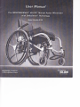
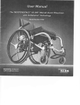
INDEPENDENCE@ |GLIDETM Manual Assist Wheelchair
Update- July 2005
Rqt*lr IvhinEnrre d VvH
ffi<s
It is critical to the proper operation of the INDEPENDENCE@ |GLIDETM Manual Assist Wheelchair that the
spokes on the rear wheels of the device be maintained. Spokes should be inspected at least once a month
to determine if any spokes are loose or broken. The following procedure should be followed while
inspecting the spokes on the rear wheel.
Spoke I nspxtion
1.
Procdurc
Transfer out of the chair and situate yourself so that you can access the spokes on one of the rear
wheels of the iGLIDETM wheelchair.
Working your way around the wheel, check each spoke by grabbing it with yourfin$ers at
approximately the center of the spoke and "wiggling" it with moderate force. Determine which of the
three situations listed below applies to each spoke you check:
tr
Broken Spoke: The spoke may break at either end of the
spoke or anyruhere along its length. lf any spoke is broken,
the wheel requires maintenance, see the Wheel Repair
Section.
o
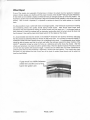
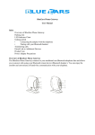
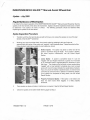
Loose Spoke: A spoke is considered loose if it can be
"wiggled" with your fingers more than a quarter of an inch total
or six millimeters total or approximately the thickness of your
little finger. The photos on the left show a loose spoke being
"wiggled" with a ruler behind it to illustrate how much a loose
spoke will move (the tape indicates the spoke being checked).
lf you are unsure of whether a spoke is loose, it is best to have
it checked by someone who is trained in maintaining wheels.
lf any spokes are suspected of being loose, see the Wheel
Repair Section.
D
Properly Tensioned Spoke: lf the spoke is not broken and
does not seem loose when wiggled, it is likely properly
tensioned.
lf any spokes are loose or broken, maintenance is required. See the Wheel Repair Section.
Check the spokes on the other wheel referring again to Step 2.
tT900057 REV 1.0
PAGE 1 OF6
Whel Repir
lf any of the spokes are suspected of being loose or broken, the wheel must be repaired or replaced.
Loose or broken spokes can interfere with the proper function of the iGLIDETM Manual Assist Wheelchair.
A new wheel can be ordered to replace a wheel with loose or damaged spokes to correct the problem. lt is
important to perform the Push Rim Assembly / Alignment Procedure when installing a new wheel (see next
section). After a wheel is replaced, it is important to continue to check it for loose spokes on a monthly
basis.
It is also possible to repair a wheel with loose or damaged spokes. Only individuals experienced in building
and maintaining wheels with spokes should attempt wheel repairs. Most bicycle repair shops have
employees who have experience working on spoked wheels who can assist you. lf a damaged spoke is
being replaced, it should be replaced with an equivalent spoke after which the wheel should be trued and
then tensioned. Use only the proper sized spoke wrench for the nipples on the wheels.
It is recommended that when the wheels on the IGLIDETM wheelchair are repaired, tensioned, and trued,
that the process be performed while the wheels are still on the chair. lt is not easy to mount the |GLIDETM
wheelchair wheels with their integral skewer into a traditional truing stand. A knowledgeable wheel builder
should be able to tension and true the wheels well within the accuracy required for proper function of the
|GLIDETM wheelchair simply by using the frame as a reference point while truing the wheels. After the
wheels are tensioned, one should be able to perform Step 2 from the Spoke lnspection Procedure above
and not have any spokes with excessive wiggle. lt should also be verified after any wheel maintenance is
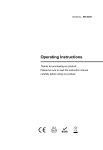
preformed that the Push Rim Assembly / Alignment is correct (see next section). One should also check
that there is a gap between the end of each arm of the hand rim spider (three places) and the wheel rim
(see the photo below).
A gap must be visible between
wheel rim and the end of the
hand rim spider arm,
tT900057 REV 1.0
PAGE 2 OF 6
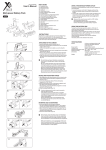
Push Rim Assembly Alignment and lnsp*tion
ln order for the iGLIDETM wheelchair power assist to function correctly, it is imperative that the Push Rim
Assembly be properly aligned. This procedure lists the steps necessary to align and inspect the Push Rim
Assembly. lt must be performed whenever the Push Rim Assembly, Wheel Assembly or CPU Drive
Assembly is replaced.
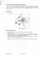
Tools Required
-
5mm Allen Wrench
\f,+
#;'
W\.1!
{-_-_/
-
i
/
i
.1,
,/.
\_.L'
,//
Rl!r-ftf.r''+.-- ---jrl
^€$il/Bl
(.:r_
Y
Figure 1- Part ldentification
Wheel Aliqnment Procedure
1.
2.
3.
Turn |GLIDETM wheelchair power off and verify that the green LED is not illuminated.
Remove the Battery.
Verify that the Push Rim Assembly is properly orientated relative to the Wheel Spokes. The correct
orientation places the arms of the Push Rim Assembly between the parallel spokes shown in Figure 2.
The two allowable positions are illustrated in Figure 3 and Figure 4.
lf the Push Rim Assembly is not properly orientated, refer to the Wheel Assembly Service lnstructions
for instructions on Push Rim Assembly installation.
NOTE: None of the Push Rim Assembly Arms are to be positioned in the same location as the valve
stem.
1T900057 REV 1.0
PAGE 3 OF 6
/
5.
6.
7.
Place both the Wheel Locks into the locked position.
Using a 5mm Allen wrench, loosen each of the 5 socket head cap screws in the Push Rim Hub lnsert
about 1/8 of a turn.
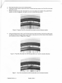
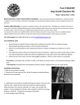
Position the topmost Push Rim Assembly Arm so that it is exactly in the middle of the parallel Wheel
Spokes, as shown in Figure 5, and tighten one of the socket head cap screws.
Figure 5 - Topmost Push Rim Assembly Arm properly centered between spokes
8.
Using just enough force to take up the free play in the Push Rim Assembly, rotate the Push Rim back
and forth and observe the gap between the Push Rim Assembly Arm and the nearest Wheel Spoke in
each direction as shown in Figure 6 and Figure 7.
Figure
6 - Push Rim Assembly Arm with free play taken up in counter-clockwise direction
Figure
7 - Push Rim Assembly
1T900057 REV 1.0
Arm with free play taken up in clockwise direction
PAGE 5 OF6
L
(
i
lf the gap noted in Step 8 is not the same in each direction, then loosen the socket head cap screw
tightened in Step 7, readjust the Push Rim Assembly Arm, and retighten the socket head cap screw.
10. Repeat Steps 8 and 9 untilthe gap found in Step 8 is the same in each direction.
lf it is not possible to move the Push Rim Assembly Arm to achieve an equal gap, then the limit of
adjustment has been reached and the Push Rim Hub lnsert will have to be repositioned.
a. Remove the 5 socket head cap screws keeping the Push Rim Hub lnsert and Push Rim
Assembly in position.
b. Rotate the Push Rim Hub lnsert CLOCKWISE until the next threaded hole is visible when
looking thru the holes in the Hub lnsert.
c. Reinstall the 5 socket head cap screws leaving them slightly loose.
d.
Adjust the Push Rim arm to achieve an equal gap following Steps 7, 8 and 9.
11. Securely tighten all 5 Push Rim Assembly socket head cap screws.
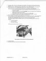
12. With one hand on the Wheel keeping it stationary, and one hand on the Push Rim, rotate the Push Rim
with reasonably heavy force, backwards and fonryards several times and observe the 3 Push Rim
Assembly arms (see Figure 8). None of the arms should contact the wheel spokes.
lf the above condition cannot be achieved, then one or more of the following items will need to be
replaced:
Push Rim Assembly
.
.
.
WheelAssembly
CPU Drive Assembly
Call the service center for further assistance.
Figure
8
Hand position for final check of Push Rim adjustment
13. lnstallthe Battery.
14. Place both the Wheel Locks into the unlocked position.
1T900057 REV 1.0
PAGE 6 OF 6
l
By agreement with the manufacturer of this Battery Charger (Panasonic, Inc.),
modifications have been made to the recommended battery charging sequence
outlined in this manual. Please follow these steps, in the sequence provided,
to most effectively charge your battery.
1.
2.
3.
4.
5.
6.
7.
8.
Connect the power cord to the AC input terminal on the charger.
Connect the charger lead to the battery.
Connect the power cord/plug to the AC (-) power outlet. Red and green LED's
on the charger are now lit. Charging now stafts.
Green LED is lit (a solid green light) during rapid charge (approx. 3.25 hours).
Trickle charge stafts after rapid charging. Green LED flashes rapidly (approx.
2 times per second) during trickle charge.
Trickle charge stops after 10 hours from stafting charge. Green LED flashes
slowly (approx. 1 time every 2 seconds) when charging cycle is complete.
Disconnect the charger lead from the battery.
Disconnect the power cord from the AC (-) power outlet.
NOTE: These steps are consistent with the instructions provided in the User Manual.
1T900152, Rev. 1.0
Page 1 of
1