1
Fury User Manual
Document:
Version:
Date:
80200505
1.2
July 17, 2012
Fury User Manual
Copyright © 2010, 2011, 2012 Jackson Labs Technologies, Inc.
Fury User Manual
1 Introduction
. . . . . . .
1.1 Overview . . . . . . . . .
1.2 General Safety Precautions . .
1.2.1 Grounding . . . . . .
1.2.2 Power Connections. . .
1.2.3 Environmental Conditions
.
.
.
.
.
.
.
.
.
.
.
.
.
.
.
.
.
.
.
.
.
.
.
.
.
.
.
.
.
.
.
.
.
.
.
.
.
.
.
.
.
.
.
.
.
.
.
.
.
.
.
.
.
.
.
.
.
.
.
.
.
.
.
.
.
.
.
.
.
.
.
.
.
.
.
.
.
.
.
.
.
.
.
.
.
.
.
.
.
.
.
.
.
.
.
.
.
.
.
.
.
.
.
.
.
.
.
.
.
.
.
.
.
.
.
.
.
.
.
.
.
.
.
.
.
.
. .
2.1 Powering Up the Unit . . . . . .
2.1.1 Power Supply Requirements .
2.1.2 Major connections . . . . .
2.1.3 Connecting the GPS Antenna.
2.1.4 Initiating Auto Survey mode .
2.1.4.1 Backup Battery . . .
2.1.5 Connecting an LCD Display .
2.1.5.1 LCD Contrast . . . .
2.1.6 Menu switch (Keypad) . . .
2.1.7 External 1PPS input option . .
2.2 Remote serial control . . . . . .
2.2.1 “Help” and command overview
2.2.2 Loop parameter adjustment .
.
.
.
.
.
.
.
.
.
.
.
.
.
.
.
.
.
.
.
.
.
.
.
.
.
.
.
.
.
.
.
.
.
.
.
.
.
.
.
.
.
.
.
.
.
.
.
.
.
.
.
.
.
.
.
.
.
.
.
.
.
.
.
.
.
.
.
.
.
.
.
.
.
.
.
.
.
.
.
.
.
.
.
.
.
.
.
.
.
.
.
.
.
.
.
.
.
.
.
.
.
.
.
.
.
.
.
.
.
.
.
.
.
.
.
.
.
.
.
.
.
.
.
.
.
.
.
.
.
.
.
.
.
.
.
.
.
.
.
.
.
.
.
.
.
.
.
.
.
.
.
.
.
.
.
.
.
.
.
.
.
.
.
.
.
.
.
.
.
.
.
.
.
.
.
.
.
.
.
.
.
.
.
.
.
.
.
.
.
.
.
.
.
.
.
.
.
.
.
.
.
.
.
.
.
.
.
.
.
.
.
.
.
.
.
.
.
.
.
.
.
.
.
.
.
.
.
.
.
.
.
.
.
.
.
.
.
.
.
.
.
.
.
.
.
.
.
.
.
.
.
.
.
.
.
.
.
.
.
.
.
.
.
.
.
.
. 3
. 3
. 3
. 4
. 5
. 6
. 7
. 7
. 8
. 8
. 9
. 10
. 11
. 11
.
3.1 Introduction . . . . . . . . . . . . . . . . .
3.2 General SCPI Commands . . . . . . . . . . .
3.2.1 *IDN? . . . . . . . . . . . . . . . . .
3.2.2 HELP?. . . . . . . . . . . . . . . . .
3.3 GPS Subsystem . . . . . . . . . . . . . . .
3.3.1 GPS:INITial . . . . . . . . . . . . . . .
3.3.1.1 GPS:INITial:DATE . . . . . . . . .
3.3.1.2 GPS:INITial:TIME . . . . . . . . .
3.3.1.3 GPS:INITial:POSition. . . . . . . .
3.3.2 GPS:POSition . . . . . . . . . . . . . .
3.3.2.1 GPS:POSition . . . . . . . . . .
3.3.2.2 GPS:POSition SURVey . . . . . .
3.3.2.3 GPS:POSition HOLDSURVey . . . .
3.3.2.4 GPS:POSition LAST . . . . . . .
3.3.2.5 GPS:POSition:SURVey:STATe ONCE
3.3.2.6 GPS:POSition:SURVey:MAXPoints . .
3.3.2.7 GPS:POSition:HOLD:LAST? . . . . .
3.3.3 GPS:REFerence . . . . . . . . . . . . .
3.3.3.1 GPS:REFerence:ADELay . . . . . .
3.3.3.2 GPS:REFerence:TRAIM . . . . . .
3.3.3.3 GPS:REFerence:TRAIM:RSVIDs? . .
3.3.3.4 GPS:REFerence:PULse:SAWtooth? . .
3.3.3.5 GPS:REFerence:PUlse:ACCuracy? . .
3.3.3.6 GPS:REFerence:PULse? . . . . . .
3.3.4 GPS:SATellite . . . . . . . . . . . . . .
3.3.4.1 GPS:SATellite:TRACking:EMANgle . .
3.3.4.2 GPS:SATellite:TRAcking:COUNt?. . .
.
.
.
.
.
.
.
.
.
.
.
.
.
.
.
.
.
.
.
.
.
.
.
.
.
.
.
.
.
.
.
.
.
.
.
.
.
.
.
.
.
.
.
.
.
.
.
.
.
.
.
.
.
.
.
.
.
.
.
.
.
.
.
.
.
.
.
.
.
.
.
.
.
.
.
.
.
.
.
.
.
.
.
.
.
.
.
.
.
.
.
.
.
.
.
.
.
.
.
.
.
.
.
.
.
.
.
.
.
.
.
.
.
.
.
.
.
.
.
.
.
.
.
.
.
.
.
.
.
.
.
.
.
.
.
.
.
.
.
.
.
.
.
.
.
.
.
.
.
.
.
.
.
.
.
.
.
.
.
.
.
.
.
.
.
.
.
.
.
.
.
.
.
.
.
.
.
.
.
.
.
.
.
.
.
.
.
.
.
.
.
.
.
.
.
.
.
.
.
.
.
.
.
.
.
.
.
.
.
.
.
.
.
.
.
.
.
.
.
.
.
.
.
.
.
.
.
.
.
.
.
.
.
.
.
.
.
.
.
.
.
.
.
.
.
.
.
.
.
.
.
.
.
.
.
.
.
.
.
.
.
.
.
.
.
.
.
.
.
.
.
.
.
.
.
.
.
.
.
.
.
.
.
.
.
.
.
.
.
.
.
.
.
.
.
.
.
.
.
.
.
.
.
.
.
.
.
.
.
.
.
.
.
.
.
.
.
.
.
.
.
.
.
.
.
.
.
.
.
.
.
.
.
.
.
.
. 13
. 13
. 13
. 13
.13
.13
. 14
. 14
. 14
. 15
. 15
. 15
. 15
. 15
. 15
. 15
. 15
.16
. 16
. 16
.16
. 16
. 16
. 16
. 17
. 17
. 17
. 17
2 Quick-Start Instructions
.
.
.
.
.
.
3 SCPI-Control Quick Start Instructions
© 2012 Jackson Labs Technologies, Inc.
1
1
1
1
1
1
i
Fury User Manual
3.4
3.5
3.6
3.7
3.8
ii
3.3.4.3 GPS:SATellite:VISible:COUNt? . . . . . . .
3.3.4.4 GPS:SATellite:VISible:COUNt? . . . . . . .
3.3.4.5 GPS:POSition 3DFix . . . . . . . . . . .
3.3.4.6 GPS:GPGGA . . . . . . . . . . . . . .
3.3.5 GPS:STATus. . . . . . . . . . . . . . . . . .
3.3.5.1 GPS:STATus . . . . . . . . . . . . . .
3.3.5.2 GPS:STATus:STRing . . . . . . . . . . .
3.3.6 GPS?. . . . . . . . . . . . . . . . . . . . .
PTIME Subsystem . . . . . . . . . . . . . . . . . .
3.4.1 PTIMe:TZONe? . . . . . . . . . . . . . . . . .
3.4.1.1 PTIMe:TZONe? . . . . . . . . . . . . .
3.4.1.2 PTIMe:DATE? . . . . . . . . . . . . . .
3.4.1.3 PTIMe:TIME? . . . . . . . . . . . . . .
3.4.2 PTIMe:TIME:STRing? . . . . . . . . . . . . . .
3.4.2.1 PTIMe:TINTerval? . . . . . . . . . . . .
3.4.2.2 PTIME? . . . . . . . . . . . . . . . .
3.4.3 PTIMe:LEAPsecond . . . . . . . . . . . . . . .
3.4.3.1 PTIMe:LEAPsecond:PENDing? . . . . . . .
3.4.3.2 PTIMe:LEAPsecond:ACCumulated? . . . . .
3.4.3.3 PTIMe:LEAPsecond:DATE? . . . . . . . .
3.4.3.4 PTIMe:LEAPsecond:DURation? . . . . . . .
3.4.3.5 PTIMe:LEAPsecond? . . . . . . . . . . .
SYNChronization Subsystem . . . . . . . . . . . . . .
3.5.1 SYNChronization:HOLDover:DURation? . . . . . . .
3.5.2 SYNChronization:SOURce:MODE . . . . . . . . .
3.5.3 SYNChronization:SOURce:STATE? . . . . . . . . .
3.5.4 SYNChronization:TINTerval? . . . . . . . . . . .
3.5.5 SYNChronization:IMMEdiate. . . . . . . . . . . .
3.5.6 SYNChronization:FEEstimate? . . . . . . . . . . .
3.5.7 SYNChronization:LOCKed? . . . . . . . . . . . .
3.5.8 SYNChronization?. . . . . . . . . . . . . . . .
3.5.9 SYNChronization:SOURce:MODE [GPS|EXTernal|AUTO]
3.5.10SYNChronization:HOLDover:DURation? . . . . . . .
3.5.11SYNChronization:HOLDover:INITiate . . . . . . . .
3.5.12SYNChronization:HOLDover:RECovery:INITiate . . . .
3.5.13SYNChronization:TINTerval? . . . . . . . . . . .
3.5.14SYNChronization:IMMEdiate . . . . . . . . . . .
3.5.15SYNChronization:FEEstimate? . . . . . . . . . . .
3.5.16SYNChronization:LOCKed? . . . . . . . . . . . .
3.5.17SYNChronization?. . . . . . . . . . . . . . . .
DIAGnostic Subsystem . . . . . . . . . . . . . . . .
3.6.1 DIAGnostic:ROSCillator:EFControl:RELative? . . . . .
3.6.2 DIAGnostic:ROSCillator:EFControl:ABSolute? . . . . .
MEASURE Subsystem . . . . . . . . . . . . . . . .
3.7.1 MEASure:TEMPerature? . . . . . . . . . . . . .
3.7.2 MEASure:VOLTage?. . . . . . . . . . . . . . .
3.7.3 MEASure:CURRent?. . . . . . . . . . . . . . .
3.7.4 MEASure? . . . . . . . . . . . . . . . . . . .
SYSTEM Subsystem . . . . . . . . . . . . . . . . .
3.8.1 SYSTem:COMMunicate . . . . . . . . . . . . .
3.8.1.1 SYSTem:COMMunicate:SERial:ECHO . . . .
3.8.1.2 SYSTem:COMMunicate:SERial:PROmpt . . .
.
.
.
.
.
.
.
.
.
.
.
.
.
.
.
.
.
.
.
.
.
.
.
.
.
.
.
.
.
.
.
.
.
.
.
.
.
.
.
.
.
.
.
.
.
.
.
.
.
.
.
.
.
.
.
.
.
.
.
.
.
.
.
.
.
.
.
.
.
.
.
.
.
.
.
.
.
.
.
.
.
.
.
.
.
.
.
.
.
.
.
.
.
.
.
.
.
.
.
.
.
.
.
.
.
.
.
.
.
.
.
.
.
.
.
.
.
.
.
.
.
.
.
.
.
.
.
.
.
.
.
.
.
.
.
.
.
.
.
.
.
.
.
.
.
.
.
.
.
.
.
.
.
.
.
.
.
.
.
.
.
.
.
.
.
.
.
.
.
.
.
.
.
.
.
.
.
.
.
.
.
.
.
.
.
.
.
.
.
.
.
.
.
.
.
.
.
.
.
.
.
.
.
.
.
.
.
.
.
.
.
.
.
.
.
.
.
.
.
.
.
.
.
.
.
.
.
.
.
.
.
.
.
.
.
.
.
.
.
.
.
.
.
.
.
.
.
.
.
.
.
.
.
.
.
.
.
.
.
.
.
.
.
.
.
.
.
.
.
.
.
.
.
.
.
.
.
.
.
.
.
.
.
.
.
.
.
.
.
.
.
.
.
.
.
.
.
.
.
.
.
.
.
.
.
.
.
.
.
.
.
.
.
.
.
.
.
.
.
.
.
.
.
.
.
.
.
.
.
.
.
.
.
.
.
.
.
.
.
.
.
.
.
.
.
.
.
.
.
.
.
.
.
.
.
.
.
.
.
.
.
.
.
.
.
.
.
.
.
.
.
.
.
.
.
.
.
.
.
.
.
.
.
.
.
.
.
.
.
.
.
.
.
.
.
.
.
.
.
.
.
.
.
.
.
.
.
.
.
.
.
.
.
.
.
.
.
.
.
.
.
.
.
.
.
.
.
.
.
.
.
.
.
.
.
.
.
.
.
.
.
.
.
.
.
.
.
.
.
.
.
.
.
.
.
.
.
.
.
.
.
.
.
.
.
.
.
.
17
17
17
17
18
18
19
19
19
20
20
20
20
20
20
20
21
21
21
21
21
21
21
22
22
22
22
22
22
23
23
23
23
23
24
24
24
24
24
24
24
25
25
25
25
25
25
25
25
26
26
26
© 2012 Jackson Labs Technologies, Inc.
Fury User Manual
3.8.1.3 SYSTem:COMMunicate:SERial:BAUD .
3.8.2 SYSTem:STATus? . . . . . . . . . . . .
3.8.3 SYSTem:FACToryReset ONCE . . . . . .
3.9 SERVO Subsystem . . . . . . . . . . . . . .
3.9.1 SERVo:COARSeDac . . . . . . . . . . .
3.9.2 SERVo:DACGain . . . . . . . . . . . .
3.9.3 . . . . . . . . . . . . . . . . . . .
3.9.4 SERVo:EFCDamping . . . . . . . . . . .
3.9.5 SERVo:SLOPe . . . . . . . . . . . . .
3.9.6 SERVo:TEMPCOmpensation . . . . . . . .
3.9.7 SERVo:AGINGcompensation . . . . . . . .
3.9.8 SERVo:PHASECOrrection . . . . . . . . .
3.9.9 SERVo:1PPSoffset . . . . . . . . . . . .
3.9.10SERVo:QUIet . . . . . . . . . . . . . .
3.9.11SERVo:TRACe . . . . . . . . . . . . .
3.9.12SERVo? . . . . . . . . . . . . . . . .
.
.
.
.
.
.
.
.
.
.
.
.
.
.
.
.
.
.
.
.
.
.
.
.
.
.
.
.
.
.
.
.
.
.
.
.
.
.
.
.
.
.
.
.
.
.
.
.
.
.
.
.
.
.
.
.
.
.
.
.
.
.
.
.
.
.
.
.
.
.
.
.
.
.
.
.
.
.
.
.
. . . . . . . . 26
. . . . . . . . 26
. . . . . . . .26
. . . . . . . . 26
. . . . . . . . 27
. . . . . . . . 27
SERVo: EFCScale28
. . . . . . . . 28
. . . . . . . . 28
. . . . . . . . 28
. . . . . . . . 28
. . . . . . . . 28
. . . . . . . . 29
. . . . . . . . 29
. . . . . . . . 29
. . . . . . . . 29
4 Firmware Upgrade Instructions .
4.1
4.2
4.3
4.4
4.5
4.6
4.7
4.8
. . . . . . . . . . . . . . . .
Introduction . . . . . . . . . . . . . . . . . . . . . . . . . . . . .
Recording Factory Calibration data . . . . . . . . . . . . . . . . . . . .
Preparing the Desktop Unit for software installation. . . . . . . . . . . . . .
Putting the PCB into In-Circuit Programming (ISP) mode . . . . . . . . . . .
ISP Flash Loader Utility installation . . . . . . . . . . . . . . . . . . . .
4.5.1 Philips LPC2000 Flash Utility . . . . . . . . . . . . . . . . . . . .
4.5.2 Flash Magic Flash Programming Utility . . . . . . . . . . . . . . . .
Downloading the firmware . . . . . . . . . . . . . . . . . . . . . . .
4.6.1 Philips LPC2000 Flash Utility . . . . . . . . . . . . . . . . . . . .
4.6.2 Flash Magic Flash Programming Utility . . . . . . . . . . . . . . . .
Updating Parameters . . . . . . . . . . . . . . . . . . . . . . . . .
Entering the calibration parameters in case the Flash was corrupted for some reason.
5 GPSCon Utility
. . . . . . . . . . . .
5.1 Description . . . . . . . . . . . . . . .
5.2 Installation . . . . . . . . . . . . . . .
5.3 Using GPSCon . . . . . . . . . . . . . .
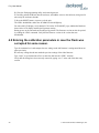
5.3.1 Setting the options . . . . . . . . . .
5.3.1.1 Communication Parameters . . .
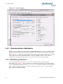
5.3.1.2 Auxiliary parameters . . . . . .
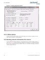
5.3.1.3 Other options . . . . . . . . .
5.3.2 Sending manual commands to the receiver
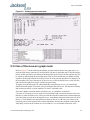
5.3.3 Use of the mouse in graph mode . . . .
5.3.4 Exporting the graphics . . . . . . . .
5.4 Interpreting the Data. . . . . . . . . . . .
6 Performance .
. . . . . . .
6.1 Introduction . . . . . . . . .
6.2 Performance Parameters . . . .
6.2.1 Allan Variance and Deviation
6.2.2 . . . . . . . . . . .
6.3 Conclusions . . . . . . . . .
© 2012 Jackson Labs Technologies, Inc.
.
.
.
.
.
.
.
.
.
.
.
.
.
.
.
.
.
.
.
.
.
.
.
.
.
.
.
.
.
.
.
.
.
.
.
.
. 31
. 31
.31
. 32
. 33
.34
.34
. 34
. 34
.34
. 36
. 39
. 40
.
.
.
.
.
.
.
.
.
.
.
.
.
.
.
.
.
.
.
.
.
.
.
.
.
.
.
.
.
.
.
.
.
.
.
.
.
.
.
.
.
.
.
.
.
.
.
.
.
.
.
.
.
.
.
.
.
.
.
.
.
.
.
.
.
.
.
.
.
.
.
.
.
.
.
.
.
.
.
.
.
.
.
.
.
.
.
.
.
.
.
.
.
.
.
.
.
.
.
.
.
.
.
.
.
.
.
.
.
.
.
.
.
.
.
.
.
.
.
.
.
.
.
.
.
.
.
.
.
.
.
.
.
.
.
.
.
.
.
.
.
.
.
.
.
.
.
.
.
.
.
.
.
.
.
.
.
.
.
.
.
.
.
.
.
.
.
.
.41
. 41
. 41
. 41
. 41
. 42
.42
. 44
. 44
.45
. 47
. 48
.
.
.
.
.
.
.
.
.
.
.
.
.
.
.
.
.
.
.
.
.
.
.
.
.
.
.
.
.
.
.
.
.
.
.
.
.
.
.
.
.
.
.
.
.
.
.
.
.
.
.
.
.
.
.
.
.
.
.
.
.
.
.
.
.
.
.
.
.
.
.
.
.
.
.
.
.
.
.
.
.
.
.
.
. 49
. 49
. 49
.49
. 51
. 51
iii
Fury User Manual
7 Certification and Warranty
7.1 Certification . . . . . . .
7.1.1 Warranty . . . . .
7.1.2 Limitation of Warranty
7.1.3 Exclusive Remedies .
iv
.
.
.
.
.
.
.
.
.
.
.
.
.
.
.
.
.
.
.
.
.
.
.
.
.
.
.
.
.
.
.
.
.
.
.
.
.
.
.
.
.
.
.
.
.
.
.
.
.
.
.
.
.
.
.
.
.
.
.
.
.
.
.
.
.
.
.
.
.
.
.
.
.
.
.
.
.
.
.
.
.
.
.
.
.
.
.
.
.
.
.
.
.
.
.
.
.
.
.
.
.
.
.
.
.
.
.
.
.
.
.
.
53
53
53
53
54
© 2012 Jackson Labs Technologies, Inc.
Fury User Manual
1
Introduction
1.1 Overview
The Fury GPSDO includes a Motorola M12+ or M12M GPS receiver, a 32bit processor that runs a
Real Time OS, LCD and Keypad interfaces, CMOS and Sine-Wave 10MHz outputs, 1PPS output,
RS-232 control interface, precision voltage references, and DACs.
Fury can be configured via the RS-232 control port to support both positive and negative EFC
control.
1.2 General Safety Precautions
The following general safety precautions must be observed during all phases of operation of this
instrument. Failure to comply with these precautions or with specific warnings elsewhere in this
manual violates safety standards of design manufacture, and intended use of the instrument. Jackson
Labs Technologies, Inc. assumes no liability for the customer’s failure to comply with these
requirements.
1.2.1 Grounding
To avoid damaging the sensitive electronic components in the Fury GSPDO always make sure to
discharge any built-up electrostatic charge to a good ground source, such as power supply ground.
This should be done before handling the circuit board or anything connected to it, i.e. the GPS
antenna.
1.2.2 Power Connections
Make sure to connect the DC power to the device following the polarity indicated in Section 2.1 . Do
not reverse the power pins as this will cause serious damage to the circuit board.
1.2.3 Environmental Conditions
This instrument is intended for indoor use. It is designed to operate at a maximum relative
non-condensing humidity of 95% and at altitudes of up to 4000 meters. Refer to the specifications
tables for the ac mains voltage requirements and ambient operating temperature range.
© 2012 Jackson Labs Technologies, Inc.
1
Fury User Manual
2
© 2012 Jackson Labs Technologies, Inc.
Fury User Manual
2
Quick-Start
Instructions
2.1 Powering Up the Unit
2.1.1 Power Supply Requirements
The Fury GPSDO requires 11.0 - 14.0V DC source capable of supplying 0.45A steady state. During
the OCXO warm-up phase the current could rise to 0.8A. The rise time from 0 to 9V should be less
than 10ms. Most switching power supplies are faster than that but a linear power supply may not
satisfy this requirement. If the rise time is less than 10ms, the unit may not power up correctly. If this
happens, it is possible to reboot the unit by pressing the Reset button after power up. See Figure 2.2
to locate the Reset button.
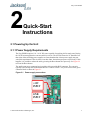
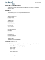
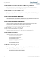
The small green power connector has its positive side toward the BNC connector. The current is
typically 0.45A steady-state with internal DOCXO. Connect a clean +12V power source to the green
connector block as shown in Figure 2.1.
Figure 2.1
Power supply connections.
+12V
INPUT
GND
INPUT
© 2012 Jackson Labs Technologies, Inc.
3
Fury User Manual
Warning: Do not reverse the polarity of the power connector. The Fury board is protected against
reverse polarity by a diode. Although the Fury won’t be damaged, it could damage the
power supply by short-circuiting it.
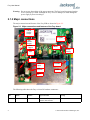
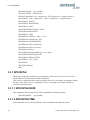
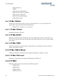
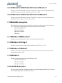
2.1.2 Major connections
The major connections and features of the Fury PCB are shown in Figure 2.2.
Figure 2.2
Major connections and features of the Fury board.
CMOS
10MHz
Output
Keypad
Sine
10MHz
Output
1PPS
Output
12V
Input
Reset
Backup
battery
RS-232
1PPS
Input
Contrast
GPS
Antenna
LCD
Alarm
Out
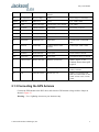
The following table shows the Fury revision 2.0 hardware connectors:
4
Ref
Name
Function
Specification
Pinning
J4
Sine Out
Sine Wave Out
10.0MHz, +7dBm (+-3dBm),
50Ohms, End-Terminate
3-Sine, 2-GND, 1-GND
© 2012 Jackson Labs Technologies, Inc.
Fury User Manual
J6
CMOS Out
TTL/CMOS Out
3.3V/5Vpp 50Ohms, Do Not
Terminate
1-Digital Output, 2-GND
JP8
J6 Output Select
J6 3.3V or 5Vpp
Jumper
3-2 J6 is 5Vpp, 2-1 J6 is 3.3Vpp
J5/Option
CMOS Out
Option for J6
(see J6)
3-TTL, 2-GND, 1-GND
JP9
Power
Clean +12V Supply
11.0V-14.0V DC, <1.0A, <10mVac
1-12V, 2-GND
JP5
Ant Power
3.3V/5V Ant Select
Jumper Option
1-2: 3.3V Ant, 2-3: 5V Ant
P1
RS-232 SYS
SCPI Control
RS-232
2-RXD, 3-TXD, 5-GND
J3
1PPS In
1PPS Input Option
3.3V max, Only use w/o GPS!
1-GND, 2-GND, 3-1PPS
JP6
ISP
Factory Diag
None
None
JP4
1PPS Select
GPS/OCXO 1PPS
Jumper Option
1-2 OCXO 1PPS, 2-3 GPS RAW
1PPS
J2
1PPS Out
1PPS Output
5V CMOS, 50Ohms, Do Not
Terminate
3-1PPS Output, 2-GND, 1-GND
J1
Alarm
Alarm Indicator
3.3V TTL, 1=Alarm, 0=OK
3-Alarm, 2-GND, 1-GND
JP3
ISP Select
Enable Flash ISP
Jumper Option
3-2 ISP enabled, 2-1 Normal
JP10
Auto Survey
GPS Auto Survey
Jumper Option
3-2 Enable Auto Survey, 2-1 Normal
J7
External 1PPS In
Backup 1PPS Input
CMOS/TTL Input (5V max).
1-GND, 3- 1PPS-in, 5- +12V
Caution: Do not short pin5
to pin 4.
JP1
Keypad Option
Keypad Connect
Short To GND to press key
5-Select Menu, 6-GND, 7-3.3V
(<20mA), 4/3/2/1 NC
JP2
LCD
16x2 LCD Connect
HD44780 Type, TTL
1-GND, 2-+5V, 3-Contrast, 4-RS,
5-RW, 6-EN, 7/8/9/10-GND, 11-DA4,
12-DA5, 13-DA6, 14-DA7, 15-LED+,
16-LED-
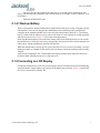
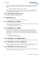
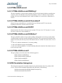
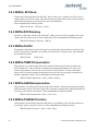
2.1.3 Connecting the GPS Antenna
Connect the GPS antenna to the BNC cable, and select the GPS Antenna voltage with the Jumper as
shown in Figure 2.3.
Warning: Use a Lightning Arrestor on your Antenna setup.
© 2012 Jackson Labs Technologies, Inc.
5
Fury User Manual
Figure 2.3
Antenna connector and configuration jumpers.
Backup
battery
GPS
AutoSurvey
Jumper
GPS
Antenna
Cable
Antenna
3.3V/5V
Selector
Reset
Button
2.1.4 Initiating Auto Survey mode
Use the “Auto Survey” jumper (see Figure 2.3) only after applying power to the unit. Momentarily
set the jumper to the position closest to the GPS receiver-can until the right-most LED (“LOCK”
LED) starts blinking at ½Hz to indicate the unit is in Auto Survey mode. Do not forget to remove this
jumper once the LOCK LED starts blinking. If the Jumper is accidentally left in the Auto Survey
position during power-on, the unit will not boot up.
The unit will need about 3 hours to one night to do auto-survey to establish its new GPS position.
Auto Survey can be started by using the Auto Survey jumper JP10, by sending an SCPI command, or
by connecting a keypad and pressing the button for 10+ seconds. Auto survey is active as long as the
"lock" LED blinks at 1/2Hz. Auto Survey mode can be queried with the “GPS?” command. “Survey
State 1” will indicate Auto Survey to be active.
Enter “GPS:POS:SURV:STAT ONCE” to start Auto Survey mode manually.
6
© 2012 Jackson Labs Technologies, Inc.
Fury User Manual
You may also enter the length of the Auto Survey (in seconds) before initiating an Auto
Survey with the following command (1000 seconds shown as an example, 10,000 seconds are set as
the default):
GPS:POS:SURV:MAXP 1000
2.1.4.1 Backup Battery
There is a known issue wth the backup battery. Sometimes the GPS receiver may not properly lock to
GPS sattelites. This has been traced to the small lithium coin-cell backup battery and potential
corruption in the Almanac and RTC that is driven by the backup battery labeled U13. The backup
battery is used to aid the GPS receiver to achieve lock faster. It is not required for normal operation,
and may be removed. (see Figure 2.3 for location of backup battery)
Removing the backup battery will sometimes actually aid in faster GPS aquisition, as well as make
the unit perform a "cold start" auto-survey automatically after power-on due to the lost almanac and
GPS receiver settings including the position-hold position.
While the backup battery can last up to 10 years if the GPS receiver is powered externally, it can also
discharge within 6 to 8 months if the board is placed in storage, and create problems when not fully
charged.
Jackson Labs Technologies, Inc. recommends removing the backup battery unless the unit has to
perform without initiating an auto-survey after power-on.
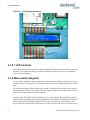
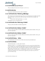
2.1.5 Connecting an LCD Display
An optional, standard 16x2 LCD with 16 pin connector may be connected to the unit for displaying
status information. Larger displays such as 20x4 LCD displays may also work. Figure 2.4 shows how
the LCD is connected to connector JP2.
© 2012 Jackson Labs Technologies, Inc.
7
Fury User Manual
Figure 2.4
LCD display connection.
2.1.5.1 LCD Contrast
The LCD contrast will likely need to be adjusted with the small blue Potentiometer next to the LCD
connector. Use a small screwdriver to carefully turn the pot (10-turn pot) until you see characters
clearly on the LCD display.
2.1.6 Menu switch (Keypad)
A single-button, momentary-short switch can be connected to pins 5 and 6 of connector JP1 (white
connector next to LCD connector). Pressing this button will cycle the LCD through its various status
pages.
The only data input that is done with the single switch is setting the unit into Auto Survey mode by
holding down the switch for 10+ seconds. All other settings are done via the SCPI interface, which is
more or less HP/Symmetricom 58503A compliant.
PLEASE NOTE THAT THE UNIT HAS TO BE SET TO “SCPI MODE” ON THE LCD FOR THE
SERIAL PORT TO WORK AND ACCEPT COMMANDS! SCPI MODE IS ENABLED BY DEFAULT
WHEN THE UNIT IS SHIPPED FROM THE FACTORY. WHEN NOT IN “SCPI MODE” THE
RS-232 BUFFER IS DISABLED. THE REASON FOR THIS IS THAT THE RS-232 BUFFER COULD
8
© 2012 Jackson Labs Technologies, Inc.
Fury User Manual
INTRODUCE SOME SWITCHING NOISE ONTO THE OUTPUTS OR ONTO THE 12V POWER
SUPPLY. THE DC-DC SWITCHING REGULATOR IS DISABLED IN ORDER TO ALLOW THE
MOST QUIET OPERATION POSSIBLE.
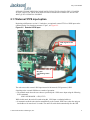
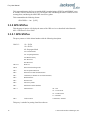
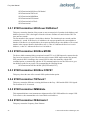
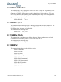
2.1.7 External 1PPS input option
Beginning with firmware version 1.15 and above, an (optional) external TTL level 1PPS input can be
connected to the Fury board on connector J7 pin 3, see Figure 2.5.
Figure 2.5
External 1PPS input.
1PPS signal on this
pin
CAUTION! +12V on
this pin!
Can damage other
pins.
The unit can use this external 1PPS input instead of the internal, GPS generated, 1PPS.
Switching to the external 1PPS has two modes of operation:
• The manual mode where the user chooses specifically the 1 PPS source input using the following
SCPI command:
SYNC:SOUR:MODE < GPS | EXT >
While in this mode, the unit will remain using this 1 PPS input even during holdover.
• In automatic mode the unit switches automatically to the external 1PPS source when the unit goes
into holdover for more than 15 seconds. The unit will switch back automatically after the GPS
© 2012 Jackson Labs Technologies, Inc.
9
Fury User Manual
1PPS source reappears for at least 3 seconds. The automatic mode can be selected with the
following SCPI command:
SYNC:SOUR:MODE AUTO
The state of the 1PPS input selection can be checked with the SCPI query SYNC:SOUR:STATe?
The 1PPS selection is stored in memory and will remain active after power cycling or reset of the
unit.
Using the external 1PPS input allows the Fury GPSDO very flexible operation in a number of
different application scenarios:
• Fury as a Rubidium Clean-Up Loop
The Fury can act as a PLL clean-up loop for noisy Rubidium sources. Connecting the Rubidium’s
1PPS output to the external 1PPS input, and setting the mode to EXT will allow the Fury to
generate a very clean, low phase-noise 10MHz and 1PPS output
• Fury with FailSafe operation:
Any external 1PPS source with long-term stability equal to, or better than the Fury’s internal
OCXO can be used to discipline the Fury in case the internal GPS receiver goes into holdover
mode for any reason such as Sat signal too weak, GPS receiver failure, antenna failure, etc.
External sources do not have to be synchronized to UTC, the 1PPS pulse may have any phase
relationship to UTC, as long as it’s stability is equal to or better than the Fury’s LTS.
• Using two cascaded Fury units as a double-redundant frequency source:
Connect the 1PPS output of one Fury to the external 1PPS input of the second unit, and set the
second unit to SYNC:SOUR:MODE AUTO. This will automatically switch the second Fury to the
first Fury’s output signal in case the second units’ internal GPS goes into holdover for whatever
reason. To provide even better reliability, both Fury’s should connect to separate GPS antennas,
and the first Fury may ultimately be connected to an external atomic clock as a triple-redundant
system in case GPS reception is totally denied for whatever reason.
The 1PPS optional input is compatible to 3.3V CMOS signals, as well as 5V TTL signals. Signals
must be 0V < x < 5.0V to prevent damage to the unit. The unit will lock onto signals with rising edge
synchronization. The signal rising edge maximum time is 10ns 10% to 90%. Pulse width should be
1us or longer. A Phase relationship to UTC is not needed on this 1PPS input. The stability of the
external 1PPS signal should be as good, or preferably significantly better than the Fury’s OCXO
long-term-stability, otherwise the performance of the Fury may actually be degraded when operating
from the external 1PPS signal.
2.2 Remote serial control
• The unit is controlled via the Serial port at 115200 baud, 8N1, but this only works if the LCD
display shows "SCPI MODE" (default setting). The RS-232 receiver is disabled outside of the
"SCPI" display page. Swap through the pages with a momentary-on type button connected to JP1
pins 5 and 6.
• Use a standard 9-pin NULL-MODEM cable to connect the Fury unit to your PC’s Hyperterminal,
or the optional GPSCon software package.
When using Hyperterminal or similar terminal program on your PC, you must disable
hardware handshaking (flow control).
10
© 2012 Jackson Labs Technologies, Inc.
Fury User Manual
2.2.1 “Help” and command overview
• A listing of the available RS-232 commands can be shown by typing in "help?".
• "*IDN?" can be used to see if the connection works. Both commands need to be followed by
pressing “Enter”.
2.2.2 Loop parameter adjustment
LOOP PARAMETERS ARE PRE-SET TO OPTIMAL VALUES BY THE FACTORY.
CHANGING THESE VALUES IS NOT NECESSARY UNDER NORMAL
CIRCUMSTANCES.
• All loop parameters can be controlled via the RS-232 serial port.
The commands to control the loop parameters are part of the servo? command. See also the SERVO
Subsystem section below.
The individual commands are:
DAC Gain: this parameter adjusts the Fury control loop to the EFC-versus-Frequency gain of your
OCXO. Some experimentation may be required to find the optimum DAC Gain for your particular
OCXO.
For typical OCXOs, the EFC gain of the OCXO can vary from +/-1Hz, to +/-20Hz for a 0V to 5V
EFC swing. HP 10811 units for example may have +/-2Hz for a full 0V to 5V swing.
Use the following approximate guidelines to adjust DAC GAIN:
MAX. OCXO
Frequency Deviation
Recommended DAC
GAIN setting
Examples
0.2Hz
2000.0
Rubidium
2Hz
250.0
10811
20Hz
30.0
Typical OCXO
40Hz
15.0
MTI OCXO
EFC Scale: this is the proportional gain of the PID loop. Higher values will give quicker
convergence, and faster locking of the GPS time (lower loop time constant), lower values give less
noise. Values between 0.7 (good double oven OCXO) and 6.0 (simple single-oven OCXO) are
typical.
© 2012 Jackson Labs Technologies, Inc.
11
Fury User Manual
EFC Damping: overall IIR filter time constant. Higher values increase loop time constant. Jackson
Labs Technologies, Inc. typically uses values between 10 to 50. Setting this value too high may cause
loop instability.
Phase compensation: This is the Integral part of the PID loop. This corrects phase offsets. Set higher
values for tighter phase-following at the expense of frequency stability. Typical values range from 4
- 30, 25 being the default. Setting this value too high may cause loop instability.
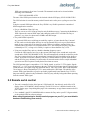
A well-compensated unit will show performance similar to the plot in Figure 2.6 when experiencing
small perturbations.
Figure 2.6
12
.Fury phase compensation plot.
© 2012 Jackson Labs Technologies, Inc.
Fury User Manual
3
SCPI-Control Quick
Start Instructions
3.1 Introduction
The SCPI (Standard Commands for Programmable Instrumentation) subsystem is accessed via the
RS-232 connector using a DB-9 Null Modem cable and a terminal program. By default the terminal
settings are 115200, 8N1.
There are a number of commands that can be used as listed below. Most of these are identical to
Symmetricom 58503A commands. To get a listing of the available commands, send the HELP?
query. This will return a list of all the available commands for the Fury GPSDO.
Additional information regarding the SCPI protocol syntax can be found on the following web site:
http://www.scpiconsortium.org
Please refer to the document SCPI-99.pdf for details regarding individual SCPI command
definitions. A basic familiarity with the SCPI protocol is recommended when reading this chapter.
3.2 General SCPI Commands
3.2.1 *IDN?
This query outputs an identifying string. The response will show the following information:
<company name>, <model number>, <serial number>, <firmware revision>
3.2.2 HELP?
This query returns a list of the commands available for the Fury GPSDO.
3.3 GPS Subsystem
The GPS subsystem regroups all the commands related to the control and status of the GPS receiver.
The list of the commands supported is the following :
© 2012 Jackson Labs Technologies, Inc.
13
Fury User Manual
GPS:INITial:DATE
<yyyy:mm:dd>
GPS:INITial:TIME
<hour:min:sec>
GPS:INITial:POSition <N|S, <deg,min,sec>, E|W <deg,min,sec>, <height in meters> >
GPS:POSition <N|S>,<deg,min,sec>, <E|W>, <deg,min,sec>, <height in meters>
GPS:POSition SURVey
GPS:POSition HOLDSURVey
GPS:POSition LAST
GPS:POSition:SURVey:STATe ONCE
GPS:POSition:HOLD:LAST?
GPS:POSition 3DFix
GPS:REFerence:ADELay <float> <s | ns >
GPS:REFerence:TRAIM ON | OFF
GPS:REFerence:TRAIM:RSVIDs?
GPS:REFerence:PULse:SAWtooth?
GPS:REFerence:PUlse:ACCuracy?
GPS:REFerence:PULse?
GPS:SATellite:TRACking:EMANgle <int> [0,89]
GPS:SATellite:TRACKing:COUNt?
GPS:SATellite:VISible:COUNT?
GPS:GPGGA <int> [0,255]
GPS:STATus?
GPS:STATus:STRing?
GPS?
3.3.1 GPS:INITial
This group of commands facilitates the initial tracking. It allows the user to give the receiver an
initial estimate of the current time and date and position
If the receiver is tracking already at least one satellite, the receiver will ignore any attempt to change
the date or time. If the receiver is computing a 3D Fix, it will ignore any attempt to change its
currently calculated position.
3.3.1.1 GPS:INITial:DATE
This command is used to enter the date. This command has the following format:
GPS:INITial:DATE
<yyyy,mm,dd>
3.3.1.2 GPS:INITial:TIME
This command is used to enter an initial time. This command has the following format:
14
© 2012 Jackson Labs Technologies, Inc.
Fury User Manual
GPS:INITial:TIME
<hour,min,sec>
3.3.1.3 GPS:INITial:POSition
This command is used to enter an estimate of the position. This command has the following format:
GPS:INITial:POSition <N|S>,<deg,min,sec>, <E|W>, <deg,min,sec>, <height>
3.3.2 GPS:POSition
This group of commands deals with the position of the GPS antenna.
3.3.2.1 GPS:POSition
This command specifies the position of the GPS antenna. The format of this command is the
following:
GPS:POSition <N|S>,<deg,min,sec>, <E|W>, <deg,min,sec>, <height in meters>
This command specifies the position of the GPS antenna. That position will become the LAST
HOLD position. To actually activate that position into the GPS receiver, use the command
GPS:POSition LAST
3.3.2.2 GPS:POSition SURVey
This command stops the current running auto-survey. The receiver will take its current average
position as its hold position.
3.3.2.3 GPS:POSition HOLDSURVey
This command does like the GPS:POSition SURVEY and also stores that position in the LAST
HOLD position.
3.3.2.4 GPS:POSition LAST
The parameter LAST denotes the LAST HOLD position . This command cancels the current
auto-survey (if any) and restores the last position setting. This command together with the command
GPS:POSition allows to skip the autosurvey process. This command is very useful when the user
knows the precise location of the GPS Antenna already.
3.3.2.5 GPS:POSition:SURVey:STATe ONCE
This command starts an auto-survey. The auto-survey lasts about 3 hours. In some occasions, it can
even last longer if the GPS antenna is not properly placed. An auto-survey can be stopped at anytime
with the command GPS:POSition SURVey.
3.3.2.6 GPS:POSition:SURVey:MAXPoints
This command specifies the number of acquisition points needed to achieve an Autosurvey. By
default, the Motorola M12+ does an average of 10000 acquisition points (e.g about three hours)
© 2012 Jackson Labs Technologies, Inc.
15
Fury User Manual
before to exit the Autosurvey. At the expense of a slightly less accurate hold position, the Autosurvey
duration can be shortened significantly using this command. This command has the following
format:
GPS:POSition:SURVey:MAXPoints <int> [0,10000]
When the unit has received the number of 1PPS signals specified by this command, it will issue a
specific command to the GPS to stop the autosurvey : this is equivalent than issuing the SCPI
command GPS:POSition HOLDSURVey.
3.3.2.7 GPS:POSition:HOLD:LAST?
This query displays the LAST HOLD position.
3.3.3 GPS:REFerence
This subgroup of commands are about the 1 PPS Reference pulse.
3.3.3.1 GPS:REFerence:ADELay
This command sets the GPS antenna delay value in seconds (or nanoseconds if the unit is specified).
The format of the command is the following:
GPS:REFerence:ADELay <float> <s | ns >
3.3.3.2 GPS:REFerence:TRAIM
This command turns on or off the M12+ T-RAIM ( Time Receiver Autonomous Integrity
Monitoring). This is an algorithm implemented in the GPS receiver that uses redundant satellite
measurements to confirm the integrity of the timing solution. This algorithm requires at least 4
tracked satellites in order to be able to generate the 1 PPS signal. T-RAIM is enabled by default on
Factory reset.
This command is the following format:
GPS:REFerence:TRAIM ON | OFF
3.3.3.3 GPS:REFerence:TRAIM:RSVIDs?
This query displays a 32-bit field number which indicates which SIDS were removed by T-TRAIM.
3.3.3.4 GPS:REFerence:PULse:SAWtooth?
This query displays the current value in nanoseconds of the negative sawtooth time error of the next
1 PPS pulse estimated by the GPS receiver. This value is in the range [-128 ns,+127ns]
3.3.3.5 GPS:REFerence:PUlse:ACCuracy?
This query displays the 1-sigma accuracy estimate in nanoseconds of the 1 PPS pulse estimated by
the GPS receiver. This value is in the range [0, 65635]
16
© 2012 Jackson Labs Technologies, Inc.
Fury User Manual
3.3.3.6 GPS:REFerence:PULse?
This query displays the status of the 1 PPS pulse. ( 0=off, 1=on )
3.3.4 GPS:SATellite
This group of commands describe the satellite constellation.
3.3.4.1 GPS:SATellite:TRACking:EMANgle
This command sets the Elevation Mask Angle. The receiver will attempt to track satellites for which
the elevation angle is greater then the satellite mask angle. The format of the command is the
following:
GPS:SATellite:TRACking:EMANgle <int> [0,89]
This parameter is set at 10 on Factory Reset.
3.3.4.2 GPS:SATellite:TRAcking:COUNt?
This query returns the number of satellites being tracked.
3.3.4.3 GPS:SATellite:VISible:COUNt?
This query returns the number of satellites (PRN) that the almanac predicts should be visible, given
date, time, and position.
3.3.4.4 GPS:SATellite:VISible:COUNt?
This query returns the number of satellites (PRN) that the almanac predicts should be visible, given
date, time, and position.
3.3.4.5 GPS:POSition 3DFix
This command places the GPS receiver in 3DFix mode instead of position-hold mode.
3.3.4.6 GPS:GPGGA
FIRMWARE REVISION 1.22 AND LATER UPDATE:
Beginning with FW rev. 1.22, the GPGGA command will actually generate both the NMEA GGA as
well as the RMC output command. The NMEA RMC string generates additional information such as
the Date, and is thus quite useful. The GPS:GPGGA command will enable or disable the GGA and
RMC strings at the same time, there is no method to generate either one or the other string
separately. Please contact the factory, or download legacy firmware revision 1.21 available on the
Jackson Labs Technologies, Inc. website under the support tab if you require the system not to
generate the RMC string.
© 2012 Jackson Labs Technologies, Inc.
17
Fury User Manual
This command instructs the Fury to send the NMEA standard strings $GPGGA and $GPRMC every
N seconds, with N in the interval [0,255]. The output is not valid during the initial 12 minute OCXO
warmup phase, and during the initial GPS Auto Survey phase.
This command has the following format:
GPS:GPGGA <int> [0,255]
3.3.5 GPS:STATus
This subgroup of queries will display the status of the GPS receiver as described in the Motorola
M12+ GPS Receiver User Guide.
3.3.5.1 GPS:STATus
The query returns a 16-bit decimal number with the following description:
Bit15-13:
111= 3D Fix
110 =2D Fix
101=Propagate Mode
100= Position Hold
011=Acquiring Satellites
010=Bad Geometry
001=Reserved
000=Reserved
Bit 12-11
Reserved
Bit 10
Narrow band tracking mode
Bit 9
Fast Acquisition Position
Bit 8
Filter Reset to Raw GPS Resolution
Bit 7
Cold Start (no almanac or out of data almanac)
Bit 6
Differential Fix
Bit 5
Position Lock
Bit 4
Autosurvey Mode
Bit 3
Insufficient Visible Satellites
Bit 2-1
Antenna Sense :
00 = OK
01 = OverCurrent
10 = UnderCurrent
11= NotValid
Bit 0
Code Location
0=External,1=Internal
This query is suitable for parsing from Host software.
18
© 2012 Jackson Labs Technologies, Inc.
Fury User Manual
3.3.5.2 GPS:STATus:STRing
This query will display the GPS status as described in the query GPS:STATus in an ASCII form
suitable for display.
3.3.6 GPS?
The query displays at once all the configuration of the GPS receiver.
Here is an example of the output of such a query:
ANTENNA DELAY:2e-09
MASK ANGLE:10
TRACKED SATS :6
VISIBLE SATS :7
SURVEY STATE :0
TIME ZONE :-7,00
ACTUAL POSITION:
N,37,17,58.9510
W,121,57,33.7390
45.40 m
LAST HOLD POSITION:
N,0,0,0.0000
E,0,0,0.0000
0.00 m
PULSE STATUS:1
PULSE ACCURACY:44
PULSE SAWTOOTH:-4
TRAIM FILTER:1
TRAIM REMOVED SVIDS:00000000
3.4 PTIME Subsystem
The PTIME subsystem regroups all the commands related to the management of the time.The list of
the commands supported is the following :
PTIMe:TZONe <hour,min> [-12,12],[0,59]
PTIMe:TZONe?
PTIMe:DATE?
PTIMe:TIME?
PTIMe:TIME:STRing?
© 2012 Jackson Labs Technologies, Inc.
19
Fury User Manual
PTIMe:TINTerval?
PTIME?
PTIMe:LEAPsecond:PENDing?
PTIMe:LEAPsecond:ACCumulated?
PTIMe:LEAPsecond:DATE?
PTIMe:LEAPsecond:DURation?
PTIMe:LEAPsecond?
3.4.1 PTIMe:TZONe?
Sets the time zone local time offset to provide an offset from UTC to serve as the basis for all
reported time. This command has the following format:
PTIMe:TZONe <hour,min> [-12,12],[0,59]
3.4.1.1 PTIMe:TZONe?
Returns the local time zone offset.
3.4.1.2 PTIMe:DATE?
This query returns the current calendar date. The local calendar date is always referenced to UTC
time, offset by any local time zone value that has been provided by the user. The year, month, and day
are returned.
3.4.1.3 PTIMe:TIME?
This query returns the current 24-hour time. The local time is referenced to UTC time. The hour,
minute, and second is returned.
3.4.2 PTIMe:TIME:STRing?
This query returns the current 24-hour time suitable for display (for example, 13:24:56).
3.4.2.1 PTIMe:TINTerval?
This query is equivalent to the command SYNChronization:TINTerval
3.4.2.2 PTIME?
This query returns at once the result of the four following queries:
PTIME:DATE?
PTIME:TIME?
PTIME:TZONE?
PTIME:TINTerval?
20
© 2012 Jackson Labs Technologies, Inc.
Fury User Manual
3.4.3 PTIMe:LEAPsecond
3.4.3.1 PTIMe:LEAPsecond:PENDing?
This query identifies if a leap second is pending. This query looks ahead to indicate a pending leap
second. A value of 0 indicates no leap second is pending. A value of 1 indicates a leap second is
pending. The leap second adjustment can be either the addition of a second or the subtraction of a
second.
3.4.3.2 PTIMe:LEAPsecond:ACCumulated?
Returns the leap second difference accumulated between GPS time and UTC time since the
beginning of GPS time. The time units are seconds.
3.4.3.3 PTIMe:LEAPsecond:DATE?
Returns the date of the future the leap second (usually UTC June 30 or UTC December 31) or the
last one if a future one is not scheduled yet.
3.4.3.4 PTIMe:LEAPsecond:DURation?
This query identifies whether a leap second is pending, distinguishes between leap seconds which
extend the minute, and leap seconds which shorten the minute. This query returns the duration of the
minute corrected by the next leap second. The duration units are seconds. The return value is 59, 60
or 61:
-A value of 59 indicates subtraction of 1 second is pending.
-A value of 60 indicates no leap second pending.
-A value of 61 indicates addition of 1 second is pending. Returns the duration of the minute corrected
by the next leap second.
3.4.3.5 PTIMe:LEAPsecond?
This query display at one the result of the 4 following queries:
PTIMe:LEAPsecond:PENDing?
PTIMe:LEAPsecond:ACCumulated?
PTIMe:LEAPsecond:DATE?
PTIMe:LEAPsecond:DURation?
3.5 SYNChronization Subsystem
This subsystem regroups the commands related to the synchronization of the Fury with the GPS
receiver. The list of the commands supported for this subsystem is the following:
SYNChronization:SOURce:MODE [GPS|EXTernal|AUTO]
SYNChronization:SOURce:STATE?
© 2012 Jackson Labs Technologies, Inc.
21
Fury User Manual
SYNChronization:HOLDover:DURation?
SYNChronization:TINTerval?
SYNChronization:IMMEdiate
SYNChronization:FEEstimate?
SYNChronization:LOCKed?
SYNChronization?
3.5.1 SYNChronization:HOLDover:DURation?
This query returns the duration of the present or most recent period of operation in the holdover and
holdover processes. This is the length of time the reference oscillator was not locked to GPS. The
time units are seconds.
The first number in the response is the holdover duration. The duration units are seconds, and the
resolution is 1 second. If the Receiver is in holdover, the response quantifies the current holdover
duration. If the Receiver is not in holdover, the response quantifies the previous holdover. The second
number in the response identifies the holdover state. A value of 0 indicates the Receiver is not in
holdover; a value of 1 indicates the Receiver is in holdover.
3.5.2 SYNChronization:SOURce:MODE
The Source:Mode command allows an optional external TTL level 1PPS input to be connected to the
Fury board, on connector J7 pin 3.The unit can use this external 1PPS input instead of the internal,
GPS generated 1PPS. Switching to the external 1PPS is either done manually with the EXT
command option, or automatically with the AUTO command option in case the GPS receiver goes
into holdover mode for any reason. The command has the following format:
SYNChronization:SOURce:MODE [GPS|EXTernal|AUTO]
3.5.3 SYNChronization:SOURce:STATE?
This query shows the state of the external 1PPS synchronization option.
3.5.4 SYNChronization:TINTerval?
This query returns the difference or timing shift between the Fury 1 PPS and the GPS 1 PPS signals.
The resolution is 1E-10 seconds.
3.5.5 SYNChronization:IMMEdiate
This command initiates a near-instantaneous alignment of the GPS 1 PPS and Receiver output 1 PPS.
To be effective, this command has to be issued while not in holdover.
3.5.6 SYNChronization:FEEstimate?
This query returns the Frequency Error Estimate.
22
© 2012 Jackson Labs Technologies, Inc.
Fury User Manual
3.5.7 SYNChronization:LOCKed?
This query returns the lock state (0=OFF, 1=ON) of the PLL controlling the OCXO.
3.5.8 SYNChronization?
This query returns the results of the four following queries :
SYNChronization:SOURce:MODE?
SYNChronization:SOURce:STATE?
SYNChronization:HOLDover:DURation?
SYNChronization:TINTerval?
SYNChronization:FEEstimate?
SYNChronization:LOCKed?
3.5.9 SYNChronization:SOURce:MODE [GPS|EXTernal|AUTO]
The board may be configured lock to an external 1PPS source, or the internal GPS receiver. A small
through-hole pad next to the SMA connectors labeled “1PPS IN” may be used to feed an external
CMOS rising-edge 1PPS signal with 0V < x <5V signal level, and 1us minimum pulse width into the
unit. Use one of the various ground pins on the board as a 1PPS signal return.
By default the unit is set to GPS. It may be hard-coded to only use the external 1PPS source by
setting EXT, or it may be auto-switched to the external 1PPS signal if the internal GPS receiver does
not generate 1PPS pulses for longer than 15 seconds if the signal is too week, or there is a GPS
failure. When set to the AUTO setting, the unit will switch back to the internal GPS receiver once
1PPS pulses are generated internally again.
3.5.10 SYNChronization:HOLDover:DURation?
This query returns the duration of the present or most recent period of operation in the holdover and
holdover processes. This is the length of time the reference oscillator was not locked to GPS. The
time units are seconds. The first number in the response is the holdover duration. The duration units
are seconds, and the resolution is 1 second. If the Receiver is in holdover, the response quantifies the
current holdover duration. If the Receiver is not in holdover, the response quantifies the previous
holdover. The second number in the response identifies the holdover state. A value of 0 indicates the
Receiver is not in holdover; a value of 1 indicates the Receiver is in holdover.
3.5.11 SYNChronization:HOLDover:INITiate
The command will place the unit into a forced holdover state, while still indicating the difference
between the internal 1PPS generated by the OCXO and the GPS generated 1PPS. This command is
useful to measure the OCXO drift when in holdover. Please note that the Time Interval Counter is
limited to +/-2000ns display range. The time interval difference may be displayed with the SYNC?
command.
© 2012 Jackson Labs Technologies, Inc.
23
Fury User Manual
3.5.12 SYNChronization:HOLDover:RECovery:INITiate
This command terminates a manual holdover that was initiated with the SYNC:HOLD:INIT
command, and return the unit to normal GPS locking mode.
3.5.13 SYNChronization:TINTerval?
This query returns the difference or timing shift between the Fury 1 PPS and the GPS 1 PPS signals.
The resolution is 1E-10 seconds.
3.5.14 SYNChronization:IMMEdiate
This command initiates a near-instantaneous alignment of the GPS 1 PPS and Receiver output 1 PPS.
To be effective, this command has to be issued while not in holdover.
3.5.15 SYNChronization:FEEstimate?
This query returns the Frequency Error Estimate, similar to the Allan Variance using a 1000s
measurement interval and comparing the internal 1PPS to GPS 1PPS offset.
Values less than 1E-012 are below the noise floor, and are not significant.
3.5.16 SYNChronization:LOCKed?
This query returns the lock state (0=OFF, 1=ON) of the PLL controlling the OCXO.
3.5.17 SYNChronization?
This query returns the results of these six queries :
SYNChronization:SOURce:MODE?
SYNChronization:SOURce:STATE?
SYNChronization:LOCKed?
SYNChronization:HOLDover:DURation?
SYNChronization:FEEstimate?
SYNChronization:TINTerval?
3.6 DIAGnostic Subsystem
This subsystem regroups the queries related to the diagnostic of the OCXO.The list of the commands
supported for this subsystem is as follows:
DIAGnostic:ROSCillator:EFControl:RELative?
DIAGnostic:ROSCillator:EFControl:ABSolute?
24
© 2012 Jackson Labs Technologies, Inc.
Fury User Manual
3.6.1 DIAGnostic:ROSCillator:EFControl:RELative?
This query returns the Electronic Frequency Control (EFC) output value of the internal reference
oscillator. It returns a percentage value between -100% to +100%. :
3.6.2 DIAGnostic:ROSCillator:EFControl:ABSolute?
This query returns the Electronic Frequency Control (EFC) output value of the internal reference
oscillator. It returns a value in volts between 0 and 5 V
3.7 MEASURE Subsystem
This subsystem regroups the queries related of some parameters that are measured on-board on the
Fury. The list of the commands supported for this subsystem is the following:
MEASure:TEMPerature?
MEASure:VOLTage?
MEASure:CURRent?
MEASure?
3.7.1 MEASure:TEMPerature?
This query returns the temperature of the sensor located next to the OCXO.
3.7.2 MEASure:VOLTage?
This query returns the power supply voltage applied to the OCXO (ca. 10.5 V )
3.7.3 MEASure:CURRent?
This query returns the current drawn by the OCXO. This current varies in order to keep a stable
temperature inside the OCXO.
3.7.4 MEASure?
This query returns the result of the three following queries:
MEASure:TEMPerature?
MEASure:VOLTage?
MEASure:CURRent?
3.8 SYSTEM Subsystem
This subsystem regroups the commands related to the general configuration of the Fury. The list of
the commands supported for this subsystem follows:
© 2012 Jackson Labs Technologies, Inc.
25
Fury User Manual
SYSTem:COMMunicate:SERial:ECHO <ON | OFF>
SYSTem:COMMunicate:SERial:PROmpt <ON | OFF>
SYSTem:COMMunicate:SERial:BAUD <9600 | 19200 | 38400 | 57600 | 115200>
SYSTem:STATus?
SYSTem:FACToryReset ONCE
3.8.1 SYSTem:COMMunicate
3.8.1.1 SYSTem:COMMunicate:SERial:ECHO
This command enables/disables echo on RS-232. It is preferable to disable the echo when used with
the software GPSCon. This command has the following format:
SYSTem:COMMunicate:SERial:ECHO <ON | OFF>
3.8.1.2 SYSTem:COMMunicate:SERial:PROmpt
This command enables/disables the prompt “scpi>” on the SCPI command lines. The prompt must be
enabled when used with the software GPSCon. This command has the following format:
SYSTem:COMMunicate: SERial:PROmpt <ON | OFF>
3.8.1.3 SYSTem:COMMunicate:SERial:BAUD
This command sets the RS-232 serial speed. The serial configuration is always 8 bit, 1 stop bit, no
parity, no HW flow control. Upon Factory reset, the speed is set at 115200 bauds. This command has
the following format:
SYSTem:COMMunicate:SERial:BAUD <9600 | 19200 | 38400 | 57600 | 115200>
3.8.2 SYSTem:STATus?
This query returns a full page of GPS status in ASCII format. The output is compatible with
GPSCon.
3.8.3 SYSTem:FACToryReset ONCE
This command applies the Factory Reset setting to the EEPROM. All aging, tempco, and user
parameters are overwritten with factory default values.
3.9 SERVO Subsystem
This subsystem regroups all the commands related to the adjustment of the servo loop:
SERVo:COARSeDac <int> [0,225]
SERVo:DACGain <int> [0.1,10000]
26
© 2012 Jackson Labs Technologies, Inc.
Fury User Manual
SERVo: EFCScale <float>[0.0 , 500.0]
SERVo:EFCDamping <float>[0.0 , 4000.0]
SERVo:SLOPe
<NEG | POS >
SERVo:TEMPCOmpensation <float> [-4000.0, 4000.0]
SERVo:AGINGcompensation <float> [-10.0, 10.0]
SERVo:PHASECOrrection <float> [-100.0, 100.0]
SERVo:1PPSoffset
<int> ns
SERVo:QUIet <ON | OFF>
SERVo:TRACe <int > [0,255]
SERVo?
3.9.1 SERVo:COARSeDac
This command sets the coarse DAC that controls the EFC. The Fury control loop automatically
adjusts this setting. The user should not have to change this value.
This command has the following format:
SERVo:COARSeDac <int> [0,225]
3.9.2 SERVo:DACGain
Adjusts the gain of the DAC circuitry to match the OCXO sensitivity to voltage changes. Typical
values are 15.0 for OCXOs with +-20Hz deviation, and 150.0 for OCXOs with +-2Hz deviation.This
command has the following format:
SERVo:DACGain <int> [0.1,10000]
THIS VALUE NEEDS TO BE ADJUSTED TO MATCH THE PARTICULAR OCXO YOU
ARE USING WITH THE FURY GPSDO.
Use the following approximate guidelines to adjust DAC GAIN:
MAX. OCXO
Frequency
Deviation
Recommended DAC GAIN
setting
Examples
0.2Hz
2000 to 5000
Rubidium
2Hz
250.0
10811
20Hz
30.0
Typical OCXO
40Hz
15.0
MTI OCXO
© 2012 Jackson Labs Technologies, Inc.
27
Fury User Manual
3.9.3 SERVo: EFCScale
Controls the Proportional part of the PID loop. Typical values are 0.7 (double oven OCXO) to 6.0
(simple single oven OCXO). Larger values increase the loop control at the expense of increased noise
while locked. Setting this value too high can cause loop instabilities.
This command has the following format:
SERVo: EFCScale <float>[0.0 , 500.0]
3.9.4 SERVo:EFCDamping
Sets the Low Pass filter effectiveness of the DAC. Values from 2.0 to 50 are typically used. Larger
values result in less noise at the expense of phase delay.This command has the following format:
SERVo:EFCDamping <float>[0.0 , 4000.0]
3.9.5 SERVo:SLOPe
The parameter determines the sign of the slope between the EFC and the frequency variation of the
OCXO. This parameter should be set to match your OCXOs EFC frequency slope. This command
has the following format:
SERVo:SLOPe
<NEG | POS >
3.9.6 SERVo:TEMPCOmpensation
This parameter is a coefficient that reflects the correlation between the Current provided to the
OCXO and the EFC. This coefficient is automatically computed and adjusted over time by the
Jackson-Labs firmware if the OCXO is powered by the Fury PCB itself. A linear relationship
between OCXO current and ambient temperature must exist for Fury to properly compensate for
ambient temperature changes. This command has the following format:
SERVo:TEMPCOmpensation <float> [-4000.0, 4000.0]
3.9.7 SERVo:AGINGcompensation
This parameter is a coefficient that represents the drift of the EFC needed to compensate the natural
drift in frequency of the OCXO due to aging. This coefficient is automatically computed and adjusted
over time by the Jackson-Labs firmware. This command has the following format:
SERVo:AGINGcompensation <float> [-10.0, 10.0]
3.9.8 SERVo:PHASECOrrection
This parameter sets the Integral part of the PID loop. Loop instability will result if the parameter is
set too high. Typical values are 10.0 to 30.0. This command has the following format:
SERVo:PHASECOrrection <float> [-100.0, 100.0]
28
© 2012 Jackson Labs Technologies, Inc.
Fury User Manual
3.9.9 SERVo:1PPSoffset
This command sets the Fury 1PPS signal’s offset to UTC in 16.7ns steps. For 1ns granularity see the
command GPS:REFerence:ADELay.
Changing the GPS:REF:ADEL parameter results in the unit slowly locking to the new UTC phase
offset. Using the SERV:1PPS command results in immediate phase change of the 1PPS signal at the
expense of a lower resolution of only 16.7ns versus 1ns.
This command has the following format:
SERVo:1PPSoffset
<int> ns
3.9.10 SERVo:QUIet
This command minimizes the output spurs by shutting down the LEDs and RS-232 transceiver. The
LCD display must be set to any other mode than “SCPI MODE” for quiet mode to be fully activated.
If SCPI mode is set, quiet mode will be disabled.
This command has the following format:
SERVo:QUIet
<ON | OFF>
3.9.11 SERVo:TRACe
This command sets the period in seconds for the debug trace. Debug trace data can be used with
Ulrich Bangert’s “Plotter” utility to show UTC tracking versus time etc.
This command has the following format:
SERVo:TRACe <int > [0,255]
3.9.12 SERVo?
This command returns the result of the following queries:
SERVo:COARSeDac?
SERVo:DACGain?
SERVo: EFCScale?
SERVo:EFCDamping?
SERVo:SLOPe?
SERVo:TEMPCOmpensation?
SERVo:AGINGcompensation?
SERVo:PHASECOrrection?
SERVo:1PPSoffset?
SERVo:TRACe?
© 2012 Jackson Labs Technologies, Inc.
29
Fury User Manual
30
© 2012 Jackson Labs Technologies, Inc.
Fury User Manual
4
Firmware Upgrade
Instructions
4.1 Introduction
The following is a short tutorial on how to upgrade the Fury GPSDO firmware. Please follow the
instructions in order to prevent corrupting the Fury Flash, which may require reflashing at the
factory.
With some practice, the entire Flash upgrade can be done in less than one minute, even though the
following seems like a fairly long list of instructions.
4.2 Recording Factory Calibration data
It is not necessary to do the following, but it is recommended that the factory calibration data is
written down on paper in case the flash update fails for some reason. Follow the steps in this section
to print out important calibration data:
A) The unit can be controlled via the Serial port at 115200 baud, 8N1 (defaults), but this only works
if the LCD display shows "SCPI MODE". In Fury Desktop units the system is set to SCPI mode by
default.
For Fury units with LCD connected, the RS-232 receiver is disabled outside of the "SCPI" display
page. Swap through the LCD menu pages with a momentary-on type button connected to JP1 pins 5
and 6 until the LCD display shows “SCPI MODE". Make sure Hyperterm is set to the same Baud rate
as shown in the LCD display (typically 115200 Baud)
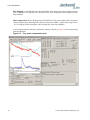
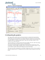
B) At the prompt, type in: serv? and press [enter]. The data displayed in Figure 4.1 will appear (or
something similar, every units data etc. will be different).
© 2012 Jackson Labs Technologies, Inc.
31
Fury User Manual
Figure 4.1
Fury factory calibration data output.
[PLEASE NOTE THAT THE ABOVE VALUES ARE REPRESENTATIVE, AND SHOULD NOT BE
ENTERED INTO YOUR FURY UNIT!]
Note down the Coarse DAC, EFC Scale, EFC damping, OCXO slope, Temperature
compensation (this value is quite important and varies from unit to unit!), aging compensation, and
Phase correction parameters so these can be typed in later in case these original values are lost for
some reason.
4.3 Preparing the Desktop Unit for software installation
In order to upgrade the Fury firmware, the desktop enclosure has to be opened.
First and most importantly, disconnect the Fury unit from AC mains power, or from any other power
source you may have connected.
Carefully remove the four screws on the faceplate (side with BNC connectors only) of the Fury units
as shown in the following picture. Please note not to tighten the screws too much when re-assembling
the unit, the screws may very easily strip the aluminum enclosure’s threads.
Remove the four screws indicated by the red arrows in Figure 4.2.
32
© 2012 Jackson Labs Technologies, Inc.
Fury User Manual
Figure 4.2
Fury faceplate removal.
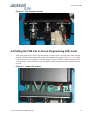
4.4 Putting the PCB into In-Circuit Programming (ISP) mode
After removing the four screws as described in the previous section., carefully pull-out the faceplate
to about 1 inch in length until the Red Jumper JP3 (marked by the red arrow in Figure 4.3) is visible.
Using tweezers or very small pliers, move the jumper JP3 (next to RS232 connector) from position
1-2 to position 2-3. Be careful not to touch the adjacent cables and connector pins with the tweezers
or pliers.
Figure 4.3
Jumper JP3 location.
© 2012 Jackson Labs Technologies, Inc.
33
Fury User Manual
Push the PCB back into the enclosure making sure that the unit is fully closed. Re-apply power to the
unit.
Now press the RESET button or power cycle the unit. If the LED’s blink, the jumper JP3 has not
been set correctly, and the unit is not in ISP mode.
The unit has now been set to ISP mode, and is awaiting the firmware download.
4.5 ISP Flash Loader Utility installation
There are two Flash loader utilities available to upgrade the Fury firmware. You can download the
Philips LPC2000 utility from the Jackson Labs Technologies, Inc. website under the Support tab:
http://www.jackson-labs.com/support.html
The Flash Magic utility is available for download on the Flash Magic website:
http://www.flashmagictool.com/
4.5.1 Philips LPC2000 Flash Utility
The first is the Philips LPC2000 utility version 2.2.3. Please note that some computers are known to
be incompatible with the LPC2000 flash utility. Preliminary investigations show Windows Media
Center and/or Centrino vPro processor systems to create download difficulties. Please use a different
computer if you experience problems such as the download breaking up in the middle of the transfer.
Or, alternatively, you may use the Flash Magic programming tool.
Please ensure that you have at least version 2.2.3 of the LPC2100 flash utility installed. Earlier
versions may not recognize the LPC2136 processor used on the Fury boards.
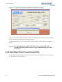
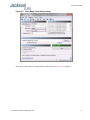
4.5.2 Flash Magic Flash Programming Utility
The second utility is the Flash Magic tool available on the Flash Magic website:
http://www.flashmagictool.com/
If the Philips LPC2000 tool doesn’t work, please use this one.
4.6 Downloading the firmware
Download the latest version of Fury firmware from the Jackson Labs Technologies, Inc. support
website and store it in a place that will be remembered. The file is in .hex format.
The unit needs to be connected to the computer’s RS-232 serial port prior to firmware download.
Connect a DB-9 serial connector to the Fury serial port, P1.
4.6.1 Philips LPC2000 Flash Utility
A) Open the LPC2000 utility. Set the COM port in the LPC2000 application as needed on your PC.
B) Select the Baud Rate of the LPC2000 utility to be 38400 or slower. Faster Baud rates will not
work properly.
34
© 2012 Jackson Labs Technologies, Inc.
Fury User Manual
C) Press the “READ DEVICE ID” button, this should then show “LPC2136” in the DEVICE
window if the unit is communicating correctly to the application.
Warning: Make sure NOT(!) to press the “erase” button under any circumstances, this may erase
factory calibration data, and the unit will not operate and will have to be returned to the
factory. Pressing the “erase” button on the ISP utility will thus void the warranty.
A) Open the LPC2000 utility. Set the COM port in the LPC2000 application as needed on your PC.
B) Select the Baud Rate of the LPC2000 utility to be 38400 or slower. Faster Baud rates will not
work properly.
C) Press the “READ DEVICE ID” button, this should then show “LPC2136” in the DEVICE
window if the unit is communicating correctly to the application.
Warning: Make sure NOT(!) to press the “erase” button under any circumstances, this may erase
factory calibration data, and the unit will not operate and will have to be returned to the
factory. Pressing the “erase” button on the ISP utility will thus void the warranty.
Figure 4.4
LPC2000 Flash Utility settings.
Please note that the “Use Baud Rate” setting needs to be set to 38400 Baud or less, it will not work
faster than 38400 Baud.
The “DEVICE” should show up as “LPC2136” after pressing “READ DEVICE ID”
Also, please point the “Filename” to the directory where you have stored the latest firmware hex file
that is to be downloaded.
D) Start the download by pressing “Upload to Flash” button. The following window should appear if
the correct COM port has been chosen etc.:
© 2012 Jackson Labs Technologies, Inc.
35
Fury User Manual
Figure 4.5
Starting the download with the LPC2000 Flash Utility.
Press the “OK” button, and the download should start. Sometimes the utility gets confused and this
process (from item 4.6 B) ) has to be tried several times.
It is not necessary to press “reset” as the utility is asking. Just press “OK” on the utility window’s
button.
Warning: DO NOT PRESS THE “ERASE” BUTTON AT ANY TIME! THIS WILL
RENDER THE PCB USELESS AND CAN ONLY BE RECOVERED AT THE
FACTORY!
4.6.2 Flash Magic Flash Programming Utility
A) Open the Flash Magic utility. Set the COM port in the Flash Magic application as needed on your
PC. Set “Interface” to “None (ISP)”.
36
© 2012 Jackson Labs Technologies, Inc.
Fury User Manual
Figure 4.6
Flash Magic Flash Utility settings.
B) Press the “Select Device” button and the window shown in Figure 4.7 will appear:
© 2012 Jackson Labs Technologies, Inc.
37
Fury User Manual
Figure 4.7
Device selection window in Flash Magic utility.
C) Expand the ARM7 folder and select the appropriate processor, in this case the LPC2136. See
Figure 4.8.
38
© 2012 Jackson Labs Technologies, Inc.
Fury User Manual
Figure 4.8
Processor selection in Flash Magic utility.
D) Select the Baud Rate of the Flash Magic utility to be 38400 or slower. Faster Baud rates will not
work properly.
E) Set the Oscillator (MHz) to “10”.
F) Check the box marked “Erase blocks used by Hex File”.
Warning: Make sure NOT(!) to check the box marked “Erase all Flash+Code Rd Prot” under any
circumstances, this may erase factory calibration data, and the unit will not operate and
will have to be returned to the factory. Checking this box on the ISP utility will thus void
the warranty.
G) Under “Step 3 - Hex File” browse for the hex file that you downloaded in step 4.6 .
H) Go to Step 5 and press “Start”. You will observe the firmware being downloaded to the Fury.
4.7 Updating Parameters
A) After the download has finished, remove power from the unit.
B) Carefully pull out the PCB as described in Section 4.4 .
C) Re-adjust jumper JP3 to pins 1-2. This will allow normal operation after a power-cycle/reset.
Please note that jumper JP3 has to be in the 1-2 position (moved in the direction of the adjacent
faceplate) in order for the unit to operate normally!
© 2012 Jackson Labs Technologies, Inc.
39
Fury User Manual
D) Close the flash programming utility, and restart hyperterm
E) Carefully push the PCB back into the enclosure, and add the screws to the enclosure, being careful
not to strip the enclosures threads.
F) Press the RESET button, or power-cycle the unit.
The LED’s should blink, and/or the ALARM LED should light up.
For units with LCD display, verify that the LCD is in the “SCPI MODE” page, and that the Baud rate
shown in the LCD display matches the Hyperterm setting.
During power on, the unit sends an ID string to Hyperterm. The firmware version can also be queried
by sending the *IDN? command. Verify that the firmware version is the version that was
downloaded.
4.8 Entering the calibration parameters in case the Flash was
corrupted for some reason.
Type the command serv? and compare the new settings to the old firmware’s settings noted down on
paper previously.
Re-enter any settings that do not match the previous settings of the older firmware.
Type “help?” to get instructions of how to enter the data into the “SERV” structure.
Verify that all settings have been correctly entered by typing “serv?” at the end of the data entry
session.
40
© 2012 Jackson Labs Technologies, Inc.
Fury User Manual
5
GPSCon Utility
5.1 Description
GPSCon is a program for the monitoring and control of a variety of GPS time and frequency standard
receivers. It communicates with the receiver using the SCPI command set. This utility can be
obtained directly from Real Ham Radio.com at the following URL:
http://www.realhamradio.com/gpscon-buy-now.htm
Important note: On newer, faster computers running Windows 7, GPSCon may not acquire data
correctly. If you encounter this problem, it is recommended that you install GPSCon on a slower
computer using Windows XP.
5.2 Installation
Follow the directions that come with GPSCon for installing the utility on your computer.
5.3 Using GPSCon
The GPSCon utility has a help file that should be consulted in order to get the full functionality of
this utility. Only a few of the features and commands are mentioned in this appendix for convenience.
5.3.1 Setting the options
To set up the options for your GPSCon session, press the “Options” button below the display area.
The window shown in Figure 5.1 will appear. You can select from the tabs which options you wish to
set.
© 2012 Jackson Labs Technologies, Inc.
41
Fury User Manual
Figure 5.1
Options window
5.3.1.1 Communication Parameters
Before you can use GPSCon you must set the communication parameters for your system. Open the
dialog box by pressing the “Options” button. Then select the “Coms” tab. You will see the window
shown in Figure 5.2. Select the correct COM port for your computer and set the baud rate to 115200,
parity to None, Data Bits to 8 and Stop Bits to 1. Set Flow Control to “None”. Once you have
configured the communication parameters, press the “OK” button to close the window.
5.3.1.2 Auxiliary parameters
After pressing the “Options” button, you can select “Auxiliary” and set other options or
measurements. See Figure 5.3 for an example of an auxiliary measurement. You will notice that the
“Aux 1 request string” has been set to meas:current?<CD> and the “Log Aux1” box is checked.
In the area below labeled “Traces to be visible on the graph”, the box “Aux 1” is checked and the
label “OCXO curr” has been added.
42
© 2012 Jackson Labs Technologies, Inc.
Fury User Manual
Figure 5.2
Setting the communications parameters
© 2012 Jackson Labs Technologies, Inc.
43
Fury User Manual
Figure 5.3
Auxiliary Parameters window
5.3.1.3 Other options
The other tabs in the options window can be selected and you can set whatever options you need,
such as paths for logging or exporting graphics.
5.3.2 Sending manual commands to the receiver
You can send SCPI commands manually by using the drop-down box under the display window as
shown in Figure 5.4. Care must be taken when sending these commands so be sure that the command
that you select is supported by the Fury GPSDO. Once you’ve selected the command, you can press
“Send” to send it to the Fury.
44
© 2012 Jackson Labs Technologies, Inc.
Fury User Manual
Figure 5.4
Sending manual commands
5.3.3 Use of the mouse in graph mode
Refer to Figure 5.5 for the following description. In graph mode the span of the graph may be set
using the span setting. Alternatively, the start and or stop time of the graph may be locked using the
mouse. Set the start time by left clicking on the desired start point. If you wish, the stop time may also
be locked by right clicking the desired stop point. This can all be unlocked by left double-clicking
anywhere on the graph. Double-click always causes all of the selected span data to be displayed. At
the next update cycle, the selected span, if not set to zero, will be enforced. However, the left click,
and if chosen the right click, always overrides the span setting.
To display all of the data in the file without manually setting the span to zero, you should right
double-click in the graph. This has the effect of setting the start time to zero, the stop time to infinity,
and asserting the mouse override condition. To release, left double-click.
Since this is harder to describe than to actually do, here is a paraphrase of the above:
"To zoom in: The mouse is used to set the left extent and the right extent of the portion of the curve
that the user wants to fill the screen. Click once with the left mouse button on the point that marks the
left side of what you want to be the magnified curve. Immediately that point becomes the left end of
the curve. Then similarly click the right mouse button on the curve at the time you wish to be the
right most portion of the magnified curve and it immediately becomes the end point on the right side.
And, finally to return to the zoomed out ("fit to window") view, left double-click on the curve."
© 2012 Jackson Labs Technologies, Inc.
45
Fury User Manual
Remember, in order to see all the data in the log file, you must either set the span control to zero, or
right double-click in the graph.
When you have locked the start and stop time using the mouse, you can scroll left or right through the
data without changing the span. To scroll to a later time, use Shift + Left click. To scroll to an earlier
time, use Shift + Right click. Double left click to release everything.
The time span indication at the lower right of the graph will turn red to signify that mouse override is
in effect.
Figure 5.5
46
Graph display
© 2012 Jackson Labs Technologies, Inc.
Fury User Manual
Figure 5.6
Expanded Graph Display
5.3.4 Exporting the graphics
The settings which control the mode of the Export function are contained in the Options dialog.
Export allows you to create an image file of either the graph or the satellite map. You select which
you want using the radio buttons. If you select 'Graph', you have the option to export only that which
is currently visible, or to export the graph which is a plot of the entire logfile contents. Use the
checkbox "All" to make this choice.
You may nominate a size in X and Y. The file format may be .BMP, .JPG, .GIF, or .PNG. Your settings
will be stored and will be the default next time you open this dialog.
If you choose to export the graph, you might want to override the TI max setting in force on the
screen display. You may do this by entering a non-zero value into the 'Override TI' control. A value
of zero causes the export to take the same setting if any as the screen display.
The export may be done automatically on a timed basis. Simply enter a non-zero value in seconds to
choose an export time interval. To manually export in accordance with the settings, press the 'Export'
button.
© 2012 Jackson Labs Technologies, Inc.
47
Fury User Manual
5.4 Interpreting the Data
Figure 5.5 shows the data acquired by the Fury unit over a period of more than 200 hours The red
trace is EFC (crystal frequency control voltage). The crystal is aging (becoming faster in frequency
over time). This requires the control voltage to be lowered to maintain 10.0MHz exactly. A drift of
~2mV is visible over 200 hours. On the left side of the screen the EFC range over this 200 hour plot
is displayed vertically as 0.00193V. This means the drift of the EFC voltage due to aging is ~88mV
per year. The EFC sensitivity of the crystal is about 8Hz per volt, so the crystal ages at:
8Hz/V * 0.088V/Year = 0.704Hz/Year drift.
At 10MHz:
0.704Hz / 10MHz = 7.04E-08 aging rate per year.
This is the same as 0.2ppb drift due to aging per day.This crystal aging is fully compensated by the
firmware with and without GPS reception of course.
The OCXO heater current is shown in turqoise. We can see it ranges from 0.135607A to 0.178146A.
The OCXO current jumps lower every 24 hours because the unit is sitting next to a window, and the
sun shines onto the OCXO in the evenings, heating it up, and thus making the unit use lower power
during that event.
In Figure 5.6, which is a zoom of Figure 5.5, we can see the phase offset error of the internal OCXO
to the UTC GPS reference. We can see the maximum drift is -77ns to +93ns. The average is (TI
av=-0.03ns). The standard deviation over the 200 hour plot is sd=11ns. This means the average error
of the 10MHz phase of this unit over 200 hours is only +/-11ns rms. Or, in other words the average
jitter (wander) over 200 hours of operation is:
11ns / 200Hrs = 1.528E-014
or in other words the unit performs as well as a high quality Cesium Atomic reference clock over
long periods of time. The unit disciplines its internal 10MHz reference to within less than +/-80ns
peak to peak of UTC at all times, which is less than one complete clock cycle at 10MHz.
48
© 2012 Jackson Labs Technologies, Inc.
Fury User Manual
6
Performance
6.1 Introduction
The Fury GPSDO represents the state-of-the-art in GPSDOs technology and provides the best
performance/price ratio available today. This chapter presents some of the performance data of the
Fury and compares it to more expensive competition.
6.2 Performance Parameters
The two (three?) most important parameters that determine the performance of a GPSDO are
frequency accuracy and stability. The stability of the clock is determined by the Allan Variance or
Allan Deviation.
6.2.1 Allan Variance and Deviation
The Allan variance (AVAR), also known as two-sample variance is a measure of frequency stability
in clocks, oscillators and amplifiers. It is named after David W. Allan. It is expressed mathematically
as:
σy 2 ( τ )
The Allan deviation (ADEV), is the square root of Allan variance. It is also known as sigma-tau, and
is expressed mathematically as:
σy ( τ )
The M-sample variance, is a measure of frequency stability using M samples, time T between
measures and observation time ?. M-sample is expressed as:
σy 2 ( M, T, τ )
© 2012 Jackson Labs Technologies, Inc.
49
Fury User Manual
The Allan variance is intended to estimate stability due to noise processes and not that of systematic
errors or imperfections such as frequency drift or temperature effects. The Allan variance and Allan
deviation describe frequency stability.
Figure 6.1 is a graph of Allan deviation (ADEV) for the DOCXO Fury in comparison to the
Symmetricon/Agilent 5071A Cesium Atomic Clock Standard costing many times more. The red
trace is the Cesium long term ADEV of a typical 5071A unit. The black trace is the ADEV of a
typical Fury DOCXO unit locked to GPS. It can be observed that the stability of the devices improves
as the averaging period gets longer, since some noise types can be removed by averaging. At some
point, however, more averaging no longer improves the results. This point is called the noise floor, or
the point where the remaining noise consists of non-stationary processes such as aging or random
walk. From the graph the following observations can be made:
• We can see that the Fury out-performs the more expensive Cesium by almost 10 to 1 at around 1
second measurement intervals.
• It performs better than the Cesium up to about 10 second measurement intervals.
• We can see that the Fury approaches the 5071A stability at about 40,000 second (11 hours)
measurement intervals.
• In the worst case the Fury compares to the 5071A at 400 second intervals with 4E-012 to 6E-013.
In other words, in the worst case, the Fury is only 6.7x worse at 400 second intervals. The Cesium
unit is almost 36x times more expensive than the Fury yet the Fury will out-perform the Cesium
over very long measurement periods.
50
© 2012 Jackson Labs Technologies, Inc.
Fury User Manual
Figure 6.1
Fury Allan Deviation
6.2.2
6.3 Conclusions
The conclusion that can be drawn from the above information is that the Fury GPSDO represents the
best performance/price ratio on the market today ....
© 2012 Jackson Labs Technologies, Inc.
51
Fury User Manual
52
© 2012 Jackson Labs Technologies, Inc.
Fury User Manual
7
Certification and
Warranty
7.1 Certification
Jackson Labs Technologies, Inc. certifies that this product met its published specifications at time of
shipment.
7.1.1 Warranty
This Jackson Labs Technologies, Inc. hardware product is warranted against defects in material and
workmanship for a period of 1 (one) year from date of delivery. During the warranty period Jackson
Labs Technologies, Inc. will, at its discretion, either repair or replace products that prove to be
defective. Jackson Labs Technologies, Inc. does not warrant that the operation for the software,
firmware, or hardware shall be uninterrupted or error free even if the product is operated within its
specifications.
For warranty service, this product must be returned to Jackson Labs Technologies, Inc. or a service
facility designated by Jackson Labs Technologies, Inc. Customer shall prepay shipping charges (and
shall pay all duties and taxes) for products returned to Jackson Labs Technologies, Inc. for warranty
service. Except for products returned to Customer from another country, Jackson Labs Technologies,
Inc. shall pay for return of products to Customer. If Jackson Labs Technologies, Inc. is unable, within
a reasonable time, to repair or replace any product to condition as warranted, the Customer shall be
entitled to a refund of the purchase price upon return of the product to Jackson Labs Technologies,
Inc.
7.1.2 Limitation of Warranty
The foregoing warranty shall not apply to defects resulting from improper or inadequate maintenance
by the Customer, Customer-supplied software or interfacing, unauthorized modification or misuse,
opening of the instruments enclosure or removal of the instruments panels, operation outside of the
environmental or electrical specifications for the product, or improper site preparation and
maintenance. JACKSON LABS TECHNOLOGIES, INC. SPECIFICALLY DISCLAIMS THE
IMPLIED WARRANTIES OF MERCHANTABILITY AND FITNESS FOR A PARTICULAR
© 2012 Jackson Labs Technologies, Inc.
53
Fury User Manual
PURPOSE. No license, express or implied, by estoppel or otherwise, to any intellectual
property rights is granted by this document. Jackson Labs Technologies, Inc. products are not
intended for use in medical, life saving, or life sustaining applications.
7.1.3 Exclusive Remedies
THE REMEDIES PROVIDED HEREIN ARE THE CUSTOMER'S SOLE AND EXCLUSIVE
REMEDIES. JACKSON LABS TECHNOLOGIES, INC. SHALL NOT BE LIABLE FOR
ANY DIRECT, INDIRECT, SPECIAL, INCIDENTAL, OR CONSEQUENTIAL DAMAGES,
WHETHER BASED ON CONTRACT, TORT, OR ANY OTHER LEGAL THEORY.
54
© 2012 Jackson Labs Technologies, Inc.