1
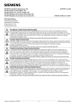
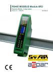
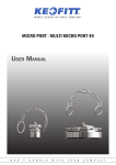
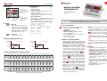
Operating manual
■ KEYBOARD
SC4
DIGITAL FAN SPEED CONTROLLER
MENU: P1 – temp [°C]
P1 – temp [°C]
P2 – min speed [%] P2 – min speed [%]
P3 – temp start [°C] P3 – temp start [°C]
P4 – mode (0 / 1) P4 – mode (0 / 1)
P5 – high temp [°C] P5 – high temp [°C]
P6 – alarm setup (0 P6
/ 1) – alarm setup (0 / 1)
P7 – inv mode (0 / 1)P7 – inv mode (0 / 1)
P8 – heater temp [°C]
P8 – heater temp [°C]
ALARM: A1 – high temp sensor
A1 1– high temp sensor 1
A3 – high temp sensor
A3 2– high temp sensor 2
A21 – sensor 1 error,A21
A22
– sensor
– sensor
1 error,
2 errorA22 – sensor 2 error
displays the current
condensaton point at the
place where the sensor is
mounted, as well as the
user’s settings
MENU
OK
FAN
N
~230V
L
IP20
N
N
L
HEATER
4-WAY COMPRESSOR EXT.
RELAY ALARM
NC COM
NC COM
1 2 3 4 5 6 7 8 9 10
setting and
confirming
parameters
SENSOR 1
C1
SENSOR 2
C2
■ TECHNICAL DATA
supply voltage
~230V
fan maximum current
3A
maximum feed current
compressor crankcase heaters (terminals 5, 6) 4A
maximum feed current
compressor contactor coils (terminals 8, 9, 12) 4A
working temp. of the device: from -30°C to +70°C
11 12 13 14
changing parameters
or increasing the value
of a given parameter
within a specific
interval
the package includes:
SC4 controller (1); temperature sensor (2); selfadhesive insulation tape (1); terminal block (1); band
clip (2); metal sheet screw (2)
changing parameters
or decreasing the value
of a given parameter
within a specific
interval
factory settings and range of available settings:
P1 = 45°C
1 – 55°C (P1 > P3)
P2 = 20%
1 – 99 %
P3 = 30°C
1 – 54°C (P3 < P1)
P4 = 0
0 – min speed or 1 – start temp
P5 = 60°C
56 – 80°C
P6 = 0
0 or 1
P7 = 0
0 or 1
P8 = 4°C
0 – 10°C
P9 = 1 sek 0 – 10 sec.
■ ALARMS
(A11) high temp
high condensation point, turns off the
compressor, at the instant the alarm
occurs, contacts 8, 9, are opened and
contacts 9, 10 are closed; the alarm
can be cancelled by pressing any key
(or turnning power off – see P6)
(A21) sensor error
temperature sensor failure
■ GRAPHS OF OPERATING MODES (P4)
V [rpm]
FAN SPEED
operating manual
ver. 41.x
Before connecting and activating the device, please read these operating
instructions and keep them for future reference
■ SC4 – NEW FUNCTIONS
The SC4 controller has new very usefull functions:
• monitoring and visualisation outdoor
temperature;
• second sensor C2 (optional);
• full heater control (5, 6 contacts) on basis
of the outdoor temperature;
• setting of hard start (0 – 10sec.), P9 parameter;
• changes of of the connection
(see connection diagram).
■ HOW THE SC3 CONTROLLER WORKS
V [rpm]
FAN SPEED
P2 – min speed (P4=0)
V max
V max
min speed
P2
min speed
P2
start temp
P3
DIGITAL FAN SPEED
CONTROLLER SC4
P3 – start temp (P4=1)
start temp
P3
temp
T [°C]
P1 TEMPERATURE
T [°C]
temp
P1 TEMPERATURE
■ TABLE OF TEMPERATURE IN RELATION TO PRESSURE
temp.
R22
R407
R410
[°C]
[bar]
[bar]
[bar]
-20
1.44
1.09
2.97
-18
1.63
1.27
3.28
-16
1.84
1.46
3.61
-14
2.06
1.66
3.96
-12
2.29
1.88
4.32
-10
2.53
2.11
4.71
-8
2.79
2.36
5.11
-6
2.06
2.62
5.54
-4
3.35
2.89
5.99
-2
3.65
3.18
6.47
0
3.97
3.49
6.96
2
4.30
3.81
7.48
4
4.65
4.15
8.03
6
5.01
4.51
8.61
temp.
R22
R407
R410
[°C]
[bar]
[bar]
[bar]
8
5.40
4.89
9.21
10
5.80
5.29
9.84
12
6.22
5.71
10.50
14
6.66
6.15
11.18
16
7.11
6.61
11.90
18
7.59
7.09
12.66
20
8.09
7.59
13.44
22
8.61
8.12
14.26
24
9.15
8.68
15.11
26
9.71
9.25
16.00
28
10.29
9.86
16.92
30
10.90
10.49
17.89
32
11.53
11.15
18.89
34
12.19
11.80
19.93
temp.
R22
R407
R410
[°C]
[bar]
[bar]
[bar]
36
12.87
12.55
21.01
38
13.58
13.30
22.13
40
14.31
14.08
23.30
42
15.07
14.89
24.51
44
15.86
15.74
25.76
46
16.67
16.62
27.05
48
17.52
17.53
28.40
50
18.39
18.48
29.78
52
19.29
19.47
31.22
54
20.23
20.50
32.70
56
21.20
21.57
34.23
58
22.20
22.68
35.81
60
23.23
23.83
37.43
62
24.20
25.03
39.11
BUDERMAN, ul. Tatrzaƒska 6b/10, 81-628 Gdynia, tel. (+48 58) 660 63 23, fax (+48 58) 660 63 30
www.buderman.com.pl e-mail: [email protected]
The SC4 controller is adapted to work in devices
requiring smooth control of rotation speed of
the fan motor (or any other element connected to
contacts 3 and 4) on the basis of temperature
measurements (sensor C1 - contacts 11, 12).
According to the entered parameters, the SC4
controller increases or decreases the fan speed in
order to maintain the required temperature measured
by the sensor C1. If the measured temperature
exceeds the temperature set by the user
(P3),
fan speed will be increased - to maximum, if need be.
If the measured temperature is still higher than the set
temperature
(P1) and reaches the alarm limit set
by the user
(P5) – then the power feed to the
compressor contactor coil (or any other element
connected to contacts 8 and 9) will be cut off. This is
a failure condition and will be signalled by the alarm
symbol
(A11) flashing on the display panel.
Return to normal operating mode is possible after the
alarm has been cancelled, by pressing any key (or
turnning power off – see P6). If the measured
temperature is lower than the
(P1), fan speed
will be reduced – to minimum
(P3), if need be.
The most common use of the SC4 controller is to
control the condenser fan motor in air conditioning,
cooling and cooling-heating devices.
OPTION: If second sensor (C2 - contacts 13, 14) is
connected, the SC4 controller can control heater
connected to contacts 5, 6. If the measured
temperature exceeds the temperature set by the user
(P8), then the contacts 5, 6 are opened. To check
outdoor temperature, press nad hold down
key.
CAUTION: This function will be work properlly, if SC4
controller is allways connected to the 230V AC power
supply.
CAUTION: If second sensor C2 is NOT connected (C2
- contacts 13, 14), SC4 controller smooth controls of
rotation speed of the fan motor and contacts 5, 6 are
closed.
■ FUNCTIONS
The controller performs the following tasks:
• maintaining a constant condensation point
• extending the life cycle of the compressor
• controlling and powering the compressor
crankcase heater on basis of temperature
measurements – sensor C2
• monitoring and visualisation of the current
condensation point – with no need to connect
pressure gauges
• smooth control of fan speed, with simultaneous
compressor activation, or with compressor
activation on reaching a previously set temperature
(condensation point)
• preventing a high condensation point and
displaying alarm conditions
Operating manual
■ INSTALLATION
CAUTION:When the SC4 controller is installed in a
device that has a four-way valve (heat pump),
the controlling signal should be connected
from the four-way valve to terminal no. 7.
On appearance of voltage (230V) from the
4-WAY valve, the controller is by-passed.
Voltage is passed directly to the condenser fan
motor.
CAUTION: CONTACT 1 IS CONNECTED TO
CONTACT 2.
CAUTION:THE SC4 CONTROLLER MAY BE INSTALLED
ONLY BY QUALIFIED PERSONNEL, WHO HAVE
THE NECESSARY AUTHORISATION – REQUIRED
BY THE REGULATIONS IN FORCE IN THE
COUNTRY WHERE THE CONTROLLER IS BEING
INSTALLED OR USED. BEFORE COMMENCING
INSTALLATION, THE DEVICE ON WHICH THE
CONTROLLER IS BEING INSTALLED MUST BE
DISCONNECTED FROM THE POWER SUPPLY
■ CONNECTION DIAGRAM
VERSION 1
FAN
L
N
N
L
HEATER
4-WAY COMPRESSOR EXT.
RELAY ALARM
NC COM
NC COM
1 2 3 4 5 6 7 8 9 10
SENSOR 1
C1
SENSOR 2
C2
11 12 13 14
M
~
sensor C1
condensation
point
fan motor
N
L
10
11,12
13,14
VERSION 2
HEATER
FAN
N
~230V
L
N
N
L
4-WAY COMPRESSOR EXT.
RELAY ALARM
NC COM
SENSOR 1
C1
SENSOR 2
C2
CAUTION:
CONTACT 2 iS CONNECTED TO CONTACT 3
TC2 < +4°C
heater
4-WAY
sensor C1
sensor C2
condensation outdoor
point
temperature
Step 2 – selection of the parameter
Press
, to select a parameter (P1 – P9).
There are nine parameters to choose from:
(P1) temp [°C]
setting the condensation point
(P2) min speed [%]
minimum fan speed at power startup
(P3) start temp [°C]
temperature at which fan is to start up
(P4) mode
operating mode selection: min speed (0)
or start temp (1)
(P5) high temp
high temperature alarm
threshold setting
(P6) alarm setup
the alarm can be cancelled by
pressing any key
or turn off and on power supply
(see table below)
P6
P6=0
TC2 > +4°C
SC4
SC4
compressor
contactor coil
alarm
(option)
Crankcase
heater ON
C2
Crankcase
heater OFF
(P7) inv mode
condition for heat pump mode
(see table below)
(P8) heater temperature
above this temperature heater is off
(contacts 5, 6 are opened)
(P9) hard start
duration of hard start
(normally 1 sec, 0-10 sec)
Step 1 – parameter setting mode
Press
. The symbol of the first parameter:
(P1).
P6=1
fan motor
M
~
After connecting the SC4 controller to the 230V AC
power supply, the currently measured temperature will
be displayed on the display panel. In order to facilitate
operation of the device, it has been equipped with a
keyboard (3 keys) and a display panel.
11 12 13 14
M
~
N
L
L
description of the connection
SC4 controller power supply phase conductor
neutral conductor
neutral conductor feeding the fan motor
phase conductor feeding the fan motor
phase conductor feeding the compressor
crankcase heater
phase conductor feeding the compressor
crankcase heater
phase conductor from the 4-WAY valve
phase conductor feeding the contactor coil
or compressor relay
phase conductor feeding the contactor coil
or compressor relay
high condensation point alarm signalling
condensation point sensor plug
outdoor temperature sensor plug
NC COM
1 2 3 4 5 6 7 8 9 10
N
7
8
9
4-WAY
heater
L
~230V
N
terminal
1
2
3
4
5
6
L
~230V
N
SC4
■ PROGRAMMING
In order to ensure correct operation of the SC4 controller,
you should:
• disconnect the factory-made power supply cables
from the fan and connect them to contacts 3, 4 in
the controller;
• connect the power supply and control cables in
accordance with the description (below);
• mount the sensor on the fourth (sixth at the furthest
– counting from the top - where the temp is
constant) elbow of the condenser. The sensor must
adhere to the elbow with its whole surface. Fasten
the sensor with the band clips and insulate it with
the insulation tape supplied with the controller.
• connect additional wire from 4WAY valve to
contacts 7 (see description below),
N
~230V
DIGITAL FAN SPEED CONTROLLER
P7
P7=0
C2
P7=1
Step 3 – changing parameter values
Press
, then change the value using the
or
key. After setting the value, press
, to save
the new setting and return to the parameter
symbol window.
Pressing and holding down
or
will
increase or reduce the values being set.
Step 4 – switching to normal operating mode
Selection of the
(P1) parameter and pressing
will switch the controller to normal
operating mode, ie. displaying the current
measured temperature.
20 seconds after the last pressing of any key, the
controller will automatically return to normal
operating mode.
cancel alarm A1
press any key
compressor
on
display
current temp.
turn off and on power SC4
(alarm A1 can not be cancelled)
off
alarm „A1”
press any key
on
current temp.
turn off and on power SC4
on
alarm „A1”
contact 9
0V
fan
smooth control of fan speed
230V
maximum fan speed (heat pump)
230V
smooth control of fan speed
0V
maximum fan speed (heat pump)