1
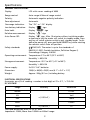
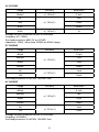
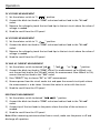
AM-220
AM-240
Digital Multimeter
User Manual
99 Washington Street
Melrose, MA 02176
Phone 781-665-1400
Toll Free 1-800-517-8431
Visit us at www.TestEquipmentDepot.com
Digital Multimeter
AM-220_AM-240 Rev003
© 2010 Amprobe Test Tools.
All rights reserved.
Owners Manual
AM-220
AM-240
Limited Warranty and Limitation of Liability
Your Amprobe product will be free from defects in material and workmanship for 1 year from
the date of purchase. This warranty does not cover fuses, disposable batteries or damage from
accident, neglect, misuse, alteration, contamination, or abnormal conditions of operation or
handling. Resellers are not authorized to extend any other warranty on Amprobe’s behalf.
To obtain service during the warranty period, return the product with proof of purchase to
an authorized Amprobe Test Tools Service Center or to an Amprobe dealer or distributor. See
Repair Section for details. THIS WARRANTY IS YOUR ONLY REMEDY. ALL OTHER WARRANTIES WHETHER EXPRESS, IMPLIED OR STAUTORY - INCLUDING IMPLIED WARRANTIES OF FITNESS FOR
A PARTICULAR PURPOSE OR MERCHANTABILITY, ARE HEREBY DISCLAIMED. MANUFACTURER
SHALL NOT BE LIABLE FOR ANY SPECIAL, INDIRECT, INCIDENTAL OR CONSEQUENTIAL DAMAGES
OR LOSSES, ARISING FROM ANY CAUSE OR THEORY. Since some states or countries do not allow
the exclusion or limitation of an implied warranty or of incidental or consequential damages,
this limitation of liability may not apply to you.
Repair
All test tools returned for warranty or non-warranty repair or for calibration should be accompanied by the following: your name, company’s name, address, telephone number, and proof of
purchase. Additionally, please include a brief description of the problem or the service requested and include the test leads with the meter. Non-warranty repair or replacement charges
should be remitted in the form of a check, a money order, credit card with expiration date, or a
purchase order made payable to Amprobe® Test Tools.
In-Warranty Repairs and Replacement – All Countries
Please read the warranty statement and check your battery before requesting repair. During the
warranty period any defective test tool can be returned to your Amprobe® Test Tools distributor for an exchange for the same or like product. Please check the “Where to Buy” section on
www.amprobe.com for a list of distributors near you. Additionally, in the United States and
Canada In-Warranty repair and replacement units can also be sent to a Amprobe® Test Tools
Service Center (see address below).
Non-Warranty Repairs and Replacement – US and Canada
Non-warranty repairs in the United States and Canada should be sent to a Amprobe® Test Tools
Service Center. Call Amprobe® Test Tools or inquire at your point of purchase for current repair
and replacement rates.
Non-Warranty Repairs and Replacement – Europe
European non-warranty units can be replaced by your Amprobe® Test Tools distributor for a
nominal charge. Please check the “Where to Buy” section on www.amprobe.com for a list of
distributors near you.
AM-220, AM-240 Digital Multimeter
Contents
Safety Information.............................................................................................................................. 4
Specifications........................................................................................................................................5
Operation.............................................................................................................................................9
1
Safety Information
SAFETY SYMBOLS
�
�
�
�
�
Warning! Dangerous Voltage (Risk of electric shock).
Caution! Refer to the user’s manual before using this Meter.
Double Insulation (Protection Class II).
Alternating Current (AC).
Direct Current (DC).
Complies with European Directives
Either DC or AC.
�
Ground (maximum permitted voltage between terminal and ground).
�
The RESPONSIBLE BODY shall be made aware that, if the instrument
is used in a manner not specified by the manufacturer, the protection
provided by the instrument may be impaired.
�
The finger or any part of your body shall not be beyond the barrier of the
test probe when measuring.
�
Conforms to relevant Australian standards
Do not dispose of this product as unsorted municipal waste
The following safety information must be observed to insure maximum personal safety
during the operation at this meter.
1.1 Do not operate the meter if the body of meter or the test leads look broken.
1.2 Check the rotary selector switch to make sure it is at the correct position before each
measurement.
1.3 When making current measurements ensure that the circuit has no voltage before
opening it in order to connect the test leads.
1.4 Do not perform resistance, capacitance, temperature, diode and continuity test
when voltage is present.
1.5 Do not apply voltage between the test terminals and test terminal to ground that
exceed the maximum limit record in this manual.
1.6 Exercise extreme caution when measuring live system with voltage greater than 60V
DC or 30V AC.
1.7 Change the battery when the “
” symbol appears to avoid incorrect data.
2
Specifications
GENERAL SPECIFICATIONS
Display:
LCD with a max. reading of 4000
Range control:
Auto range & Manual range control
Polarity:
Automatic negative polarity indication
Zero adjustment:
Automatic
Overrange indication:
The “OL” or “-OL” display
Low battery indication:
Display “
Data hold:
Display “
Relative measurement:
Display “
Auto Power Off:
Display “ ” sign. After 10 minutes without switching modes
or pressing a key the meter will switch to standby mode. Press
any key or switch selector switch to exit standby mode. To disable auto power off, press and hold SELECT key while rotating
the selector switch from off position.
Safety standards:
EMC/LVD. The meter is up to the standards of
EN61010-1:2001; Double Insulation, Pollution Degree 2,
Overvoltage Category III-600V.
“ sign
” sign
” sign
Operating environment: Temperature 0°C to 40°C (32°F to104°F)
Humidity °< 80% RH
Storage environment:
Temperature -20°C to 60°C (-4°F to140°F)
Humidity °< 90% RH
Power supply:
2x1.5V “AA” batteries
Dimension:
156(H) x 86(W) x 38(D) mm (6.1“ x 3.4“ x 1.5“)
Weight:
Approx. 260g (9.2 oz.) including battery
ELECTRICAL SPECIFICATIONS
Accuracies are ±(% of reading + number in last digit) at 23 ± 5°C, °< 75% RH
DC VOLTAGE
Range
Accuracy
400mV
4V
40V
0.1mV
± ( 0.5%+2 )
400V
600V
Resolution
1mV
10mV
100mV
± ( 0.8%+3 )
Overload protection: 600V DC or AC RMS
Impedance: 10MW, More than 100MW on 400mV range
3
1V
AC VOLTAGE
Range
Accuracy
Resolution
400mV
± ( 1.5%+3 )
0.1mV
± ( 1.0%+2 )
10mV
4V
40V
1mV
400V
600V
100mV
± ( 1.5%+3 )
1V
Average sensing, calibrated to RMS of sine wave
Frequency: 40 ~ 400Hz
Overload protection: 600V DC or AC RMS
Impedance: 10MW , More than 100MW on 400mV range
DC CURRENT
Range
Accuracy
400μA
4000μA
40mA
0.1μA
± ( 1.2%+3 )
400mA
4A
10A
Resolution
1μA
10μA
100μA
± ( 2.0%+5 )
1mA
10mA
Overload protection: 0.5A/250V, 10A/250V fuse
AC CURRENT
Range
Accuracy
400μA
4000μA
40mA
0.1μA
± ( 1.5%+3 )
400mA
4A
10A
Resolution
1μA
10μA
100μA
± ( 2.5%+5 )
Average sensing, calibrated to RMS of sine wave
Frequency: 40~400Hz
Overload protection: 0.5A/250V, 10A/250V fuse
4
1mA
10mA
RESISTANCE
Range
Accuracy
Resolution
400W
0.1W
4kW
40kW
1W
± ( 1.0%+5 )
10W
400kW
100W
4MW
40MW
1kW
± ( 2.0%+3 )
10kW
Overload protection: 250V DC or AC RMS
CAPACITANCE
Range
Accuracy
Resolution
40nF
± ( 3.0%+10 )
400nF
4μF
10pF
100pF
± ( 2.5%+5 )
1nF
40μF
10nF
400μF
± ( 5.0%+10 )
100nF
4000μF
± ( 20.0%+20 )
1μF
Overload protection: 250V DC or AC RMS
DIODE AND AUDIBLE CONTINUITY TEST
Range
Description
Test condition
Display read approximately
forward voltage of diode
Forward DC current approx. 0.4mA
Reversed DC voltage approx. 2.8V
Built-in buzzer sounds if resistance
is less than 50W
Open circuit voltage approx. 0.5V
Overload protection: 250V DC or AC RMS
5
FREQUENCY
Range
Accuracy
Resolution
10Hz
0.01Hz
100Hz
0.1Hz
1000Hz
10kHz
1Hz
± ( 0.1%+5 )
100kHz
10Hz
100Hz
1000kHz
1kHz
10MHz
10kHz
Sensitivity: sine wave 0.6V RMS (10MHz: 1.5V RMS)
Overload protection: 250V DC or AC RMS
DUTY CYCLE
0.1% ~ 99.9%: ± (2.0%+2) Frequency lower than 10kHz
Sensitivity: sine wave 0.6V RMS
Overload protection: 250V DC or AC RMS
TEMPERATURE (AM-240 ONLY)
•
Accuracy specification is relative to the user-adjustable temperature offset, and
assumes ambient temperature stable to ± 1°C.
•
For ambient temperature changes of ± 5°C, rated accuracy applies after 1 hour.
•
Does not include error of the thermocouple probe
Range
Accuracy
-58ºF ~ +1292ºF
+/-(2.8% + 9ºF)
-50ºC ~ +700ºC
+/-(2.8% + 7ºC)
Overload protection: 250V DC or AC RMS
6
Resolution
1° /1°F
Operation
DC VOLTAGE MEASUREMENT
1) Set the selector switch to “V
” position.
2) Connect the black test lead to “COM” socket and red test lead to the “VW mA”
socket.
3) Measure the voltage by touch the test lead tips to the test circuit where the value of
voltage is needed.
4) Read the result from the LCD panel.
AC VOLTAGE MEASUREMENT
1) Set the selector switch to “V
” position.
2) Connect the black test lead to “COM” socket and red test lead to the “VW mA”
socket.
3) Measure the voltage by touch the test lead tips to the test circuit where the value of
voltage is needed.
4) Read the result from the LCD panel.
DC AND AC CURRENT MEASUREMENT
1) Set the selector switch to desired “μA
”, “mA
” or “A
” position.
2) Connect the black test lead to “COM” socket. For measurement up to 400mA, connect the red test lead to the “VW mA” socket; for measurement from 400mA to 10A,
connect the red test lead to the “10A” socket
3) Press “SELECT” key to choose “DC” or “AC” measurement.
4) Remove power from the circuit under test and open the normal circuit path where
the measurement is to be taken. Connect the meter in series with the circuit.
5) Read the result from the LCD panel.
RESISTANCE MEASUREMENT
1) Set the selector switch to desired “
” position.
2) Connect the black test lead to “COM” socket and red test lead to the “VW mA”
socket.
3) Connect tip of the test leads to the points where the value of the resistance is
needed.
4) Read the result from the LCD panel.
Note: When measuring resistance values from a circuit, make sure the power is off and
discharge all capacitors.
7
CAPACITANCE MEASUREMENT
1) Set the selector switch to desired “
” position.
2) Connect the black test lead to “COM” socket and red test lead to the “VW mA”
socket.
3) Press “SELECT” key to choose Capacitance measurement.
4) Connect tip of the test leads to the points where the value of the capacitance is needed.
5) Read the result from the LCD panel.
Note:
a) Before testing, discharge the capacitor by shorting its leads together. Use caution in
handling capacitors because they may have a charge on them of considerable power.
b) Before testing, press “REL
c)
” key to eliminate the zero error.
When testing 4000μF capacitor, note that there will be approx. 30 seconds time lag.
DIODE AND AUDIBLE CONTINUITY TEST
1) Set the selector switch to desired “
” position.
2) Connect the black test lead to “COM” socket and red test lead to the “VW mA”
socket.
3) Press “SELECT” key to choose Diode or Audible Continuity measurement.
4) Connect the test leads across the diode under test, display measures the approx. forward voltage of this diode.
5) Connect the test leads to two point of circuit, if the resistance is lower than approx.
50W, the buzzer sounds.
Note: Make sure the power is cut off and all capacitors need to be discharged under this
measurement.
FREQUENCY AND DUTY CYCLE MEASUREMENT
1) Set the selector switch to desired “Hz” position.
2) Connect the black test lead to “COM” socket and red test lead to the “VW mA”
socket.
3) Press “Hz%” key to choose Frequency or Duty Cycle measurement.
4) Connect the probe across the source or load under measurement.
5) Read the result from the LCD panel.
8
TEMPERATURE MEASUREMENT (AM-240 Only)
1) Set the selector switch to desired “°F/ °C” position.
2) Press “SELECT” key to choose °F or °C measurement.
3) There is an internal PN Junction Diode Sensor which measures ambient temperature
with no probe connected. This is the 0~40° in the spec.
4) Connect the probe included, or any K-type thermocouple, by inserting the “+” plug
in the “VW mA” socket & the “-“ in the “COM” socket
5) Put the sensor probe into the temperature field under measurement.
DATA HOLD AND BACK LIGHT
On any range, press the “
” key to lock display value, and the
” sign will appear on the display, press it again to exit. On any range, press the
“
” key for more than 2 seconds to light the back light, press it again for
“
more than 2 seconds to wink the light.
MAX/MIN HOLD
Press the “MAX/MIN” key to lock MAX or MIN value, and the “MAX” or “MIN” sign will
appear on the display, press it for more than 2 seconds to exit.
RELATIVE MEASUREMENT
” key, you can measure the relative value and “ ” sign will appear
Press the “REL
on the display, the auto range mode be changed to manual range mode. Press it again
to exit relative measurement and “ ” sign disappears, but you cannot go back to auto
range mode. This function is non effective on Hz% measurement.
AUTO/MANUAL RANGE
The auto range mode is a convenient function, but it might be faster to manually set the
range when you measure values that you know to be within a certain range. To select
manual range, repeatedly press “RANGE” key until the display shows the desired range.
The range steps upward as you press “RANGE” key. The meter will go back to auto range
mode when you press “RANGE” key for more than 2 seconds. It can not select manual
range mode on Hz%, capacitance and temperature range.
Caution: while using the manual range mode, if “OL” sign appears on the display,
immediately set range to a higher.
9
BATTERY REPLACEMENT
1) When the battery voltage drops below proper operating range, the “
will appear on the LCD and the batteries needs to be changed.
” symbol
2) Before changing the batteries, set the selector switch to “OFF” position. Remove the
two screws on the bottom case and lift the bottom case.
3) Replace the old batteries with the same type battery.
4) Close the bottom case and fasten the screw.
FUSE REPLACEMENT
1) This meter is provided with a 0.5A/250V fuse to protect the current measuring
circuits that measure up to 400mA, with a 10A/250V fuse to protect the 10A range.
2) Ensure the instrument is not connected to any external circuit, set the selector switch
to “OFF” position and remove the test leads from the terminals.
3) Remove the two screws on the bottom case and lift the bottom case. Replace the old
fuse with the same type and rating: 5x20mm 0.5A/250V or 6x32mm 10A/250V fuse.
4
Close the bottom case and fasten the screws.
MAINTENANCE
1) Before opening the bottom case, disconnect both test leads and never use the meter
before the bottom case is closed.
2) To avoid contamination or static damage, do not touch the circuit board without
proper static protection.
3) If the meter is not going to be used for a long time, take out the batteries and do
not store the meter in high temperature or high humidity environment.
4) Repairs or servicing not covered in this manual should only by qualified personnel.
5) Periodically wipe the case with a damp cloth and detergent. Do not use abrasives or
solvents on the meter.
10