1
M.E. 530.420 JHU Robot Sensors and Actuators Education Board (JHURSAEB) and MaEvArM User Manual Yonjae Kim and Louis L. Whitcomb Department of Mechanical Engineering Johns Hopkins University Revision 22 – July 5, 2012 Download the latest version of this manual here: https://dscl.lcsr.jhu.edu/JHURSAEB JHURSAEB Contents Contents 0 Modification History .............................................................................................................................v 0.1 2011-‐09-‐14 Revision 17 ...............................................................................................................v 0.2 2011-‐09-‐20 Revision 18 ................................................................................................................v 0.2.1 Revised recommended user project directory to work on Windows 7 PCs in Wyman 140 .v 0.2.2 Added documentation for new function USART_printf() to Section 11 USART – maevarmUSART.h/.c.............................................................................................................................v 0.3 2011-‐09-‐27 Revision 19 Corrected directory typos on pages iv and 4. ........................................v 0.4 2012-‐04-‐11 Revision 20 Update to match library updates and explanation of JHURSAEB’s soft reset button ..............................................................................................................................................v 1 2 3 Introduction......................................................................................................................................... 1 1.1 Resources..................................................................................................................................... 1 1.2 JHURSAEB Board Layout .............................................................................................................. 2 1.3 JHURSAEB Board B4 RST Button: ................................................................................................. 3 Development Environment Installation............................................................................................... 4 2.1 Installing the Atmel Development Environment for Windows.................................................... 4 2.2 Installing the JHURSAEB and MaEvArM library and header files ................................................. 4 Creating, Compiling, and Running Code on the JHURSAEB/MaEvArM................................................ 4 3.1 Setting up your project: ............................................................................................................... 4 3.2 Linker Options: Setting up your project to use usb_printf() and usb_scanf() and the standard C math library ............................................................................................................................................. 7 3.3 Simple Project Source Code Example .......................................................................................... 9 3.4 Compiling, Downloading, and Running Your Project: ................................................................ 10 3.5 Serial Terminal Emulators:......................................................................................................... 11 3.5.1 Terminal: (Recommended for this course) ........................................................................ 11 3.5.2 SerialChart: ........................................................................................................................ 11 3.5.3 Termite: ............................................................................................................................. 11 3.6 General Tips, FAQ, and Troubleshooting ................................................................................... 12 4 Using this Manual: Name of Source Code and Header File ............................................................... 13 5 USB Communication – maevarmUSB.h/.c ......................................................................................... 14 5.1 usb_initialize()............................................................................................................................ 14 5.2 usb_printf() ................................................................................................................................ 15 Page | i Contents 5.3 6 usb_scanf ................................................................................................................................... 16 General MaEvArM Functions -‐ maevarmGEN.h/.c ............................................................................ 17 6.1 delay_ms() ................................................................................................................................. 17 6.2 delay_us() .................................................................................................................................. 17 6.3 IO_mode().................................................................................................................................. 18 6.4 IO_out()...................................................................................................................................... 19 6.5 IO_read().................................................................................................................................... 20 7 Analog to Digital Converter -‐ maevarmADC.h/.c ............................................................................... 21 7.1 ADC_enable() ............................................................................................................................. 21 7.2 ADC_set_AREF()......................................................................................................................... 21 7.3 ADC_set_CLK() ........................................................................................................................... 22 7.4 ADC_set_channel() .................................................................................................................... 22 7.5 ADC_disable_digital()................................................................................................................. 23 7.6 ADC_justify() .............................................................................................................................. 23 7.7 ADC_read()................................................................................................................................. 24 7.8 ADC_readH() .............................................................................................................................. 25 7.9 ADC_disable() ............................................................................................................................ 25 8 Serial Peripheral Interface -‐ maevarmSPI.h/.c................................................................................... 26 8.1 SPI_MasterInit() ......................................................................................................................... 26 8.2 SPI_data_order()........................................................................................................................ 27 8.3 SS_low() ..................................................................................................................................... 28 8.4 SS_high() .................................................................................................................................... 28 8.5 SPI_send() .................................................................................................................................. 29 8.6 SPI_read() .................................................................................................................................. 30 9 8-‐Bit Timer/Counter 0 – maevarmTMR0.h/.c.................................................................................... 31 9.1 TMR0_source() .......................................................................................................................... 32 9.2 TMR0_set_mode() ..................................................................................................................... 32 9.3 TMR0_X_mode() //X = A, or B ................................................................................................... 33 9.4 TMR0_X_value() //X = A or B ..................................................................................................... 34 10 16-‐Bit Timer/Counter 1 – maevarmTMR1.h/.c .............................................................................. 35 10.1 TMR1_source() .......................................................................................................................... 36 10.2 TMR1_set_mode() ..................................................................................................................... 37 Page | ii Contents 10.3 TMR1_X_mode() //X = A, B, or C ............................................................................................... 38 10.4 TMR1_X_value() //X = A, B, or C ................................................................................................ 39 10.5 TMR1_IC_noise_canceller() ....................................................................................................... 40 10.6 TMR1_IC_edge_select()............................................................................................................. 40 10.7 TMR1_IC_read()......................................................................................................................... 41 10.8 TMR1_pulsein().......................................................................................................................... 42 10.9 TMR1_IC_clear() ........................................................................................................................ 43 11 16-‐Bit Timer/Counter 3 – maevarmTMR3.h/.c .............................................................................. 44 11.1 TMR3_source() .......................................................................................................................... 45 11.2 TMR3_set_mode() ..................................................................................................................... 45 11.3 TMR3_X_mode() //X = A, B, or C ............................................................................................... 46 11.4 TMR3_X_value() //X = A, B, or C ................................................................................................ 46 11.5 TMR3_IC_noise_canceller() ....................................................................................................... 47 11.6 TMR3_IC_edge_select()............................................................................................................. 47 11.7 TMR3_IC_read()......................................................................................................................... 47 11.8 TMR3_pulsein().......................................................................................................................... 48 11.9 TMR3_IC_clear() ........................................................................................................................ 48 12 Two Wire Interface (I2C) Functions -‐ maevarmTWI.h/.c ............................................................... 49 12.1 TWI_enable() ............................................................................................................................. 49 12.2 TWI_bitrate() ............................................................................................................................. 49 12.3 TWI_start()................................................................................................................................. 50 12.4 TWI_tx_address()....................................................................................................................... 50 12.5 TWI_tx_data() ............................................................................................................................ 51 12.6 TWI_stop() ................................................................................................................................. 51 12.7 TWI_disable()............................................................................................................................. 52 13 USART – maevarmUSART.h/.c ....................................................................................................... 53 13.1 USART_init()............................................................................................................................... 53 13.2 USART_size() .............................................................................................................................. 54 13.3 USART_set_parity().................................................................................................................... 54 13.4 USART_set_stopbit().................................................................................................................. 54 13.5 USART_tx_enable() .................................................................................................................... 55 13.6 USART_tx() ................................................................................................................................. 55 Page | iii Contents 13.7 USART_tx9() ............................................................................................................................... 56 13.8 USART_tx_disable().................................................................................................................... 56 13.9 USART_rx_enable() .................................................................................................................... 57 13.10 USART_rx() ............................................................................................................................. 57 13.11 USART_rx9() ........................................................................................................................... 58 13.12 USART_rx_disable()................................................................................................................ 58 13.13 USART_printf() ....................................................................................................................... 59 Page | iv Contents 0
Modification History 0.1 2011-‐09-‐14 First release 0.2 2011-‐09-‐20 0.2.1
Revision 17 Revision 18 Revised recommended user project directory to work on Windows 7 PCs in Wyman 140 This is a change to Section 3 Creating, Compiling, and Running Code on the JHURSAEB/MaEvArM: We can’t use C:\RSA_2011\your_name to store your project files because the directory is protected. Since you will be logged in as “Guest”, store your projects in the following directory. C:\Users\Guest\RSA_2011\your_name\ for example: C:\ Users\Guest\RSA_2011\Whitcomb\My_Hello_World_Project 0.2.2
Added documentation for new function USART_printf() to Section 13 USART – maevarmUSART.h/.c Added documentation for new function USART_printf() to Section 13 USART – maevarmUSART.h/.c 0.3 2011-‐09-‐27 Revision 19 Corrected directory typos on pages iv and 4. Example user directory corrected to read as follow in page iv and page 4: C:\ Users\Guest\RSA_2011\Whitcomb\My_Hello_World_Project 0.4 2012-‐04-‐11 Revision 20 Update to match library updates and explanation of JHURSAEB’s soft reset button Changed font of “-‐Wl,-‐u,vfprintf” to make l (lowercase L) be differentiable from an upper case i. Added additional explanation about usb_initialize(). Added TMR0 and TMR3 sections. 0.5 2012-‐06-‐28 Revision 22 Updated MaEvArM graphics for Rev. 4.0 of the board and fixed minor typos. Added note about setting up the USB Serial driver on Windows. Updated links to JHURSAEB website.
Page | v 1 Introduction 1
Introduction The JHU Robot Sensors and Actuators Education Board (JHURSAEB) is a microprocessor development board for use in undergraduate robotics laboratory courses at the Department of Mechanical Engineering, Johns Hopkins University. This board utilizes at the MaEvArM microcontroller platform developed by Prof. Jonathan Fiene at the Department of Mechanical Engineering and Applied Mechanics, University of Pennsylvania. The MaEvArM utilizes Amtel’s ATmega32U4 microcontroller. The USB interface built into this microcontroller allows programming of the device directly from a host computer via USB without the need for an external dongle, but the device can also be programmed and debugged through the SPI and JTAG interface. The coding of ATmega32U4 can be written in C using AVR Studio 4 and the GCC compiler. Once compiled, the hex file can be uploaded into the microcontroller through the USB interface using the Flip program. More details on setup and starting up can be found on UPenn’s MaEvArM page (link below) and in the Getting Started section. Programming the ATmega32U4 involves manipulating individual bits in the registers to get the functions that you want. The ATmega32U4 datasheet (also below) gives extensive explanations on the usage and functions of the different modules in the microcontroller, and how to use the related registers. For the purposes of the class, we have made header files that will perform these register manipulations for you, and they are described below. 1.1 Resources Header Files/source code (.zip): The latest version is available as a zip file here: https://dscl.lcsr.jhu.edu/JHURSAEB MaEvArM Page at UPenn: https://alliance.seas.upenn.edu/~medesign/wiki/index.php/Guides/MaEvArM MaEvArM USB Communication Page (contains download for usb source code and header): https://alliance.seas.upenn.edu/~medesign/wiki/index.php/Guides/MaEvArM-‐usb Amtel’s ATmega32U4 Page (Documents section contains many sample codes): http://www.atmel.com/dyn/products/product_card.asp?part_id=4317 Amtel’s ATmega32U4 Datasheet (Provides explanation and sample codes): http://www.atmel.com/dyn/resources/prod_documents/doc7766.pdf Page | 1 1 Introduction 1.2
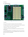
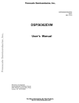
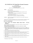
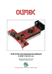
JHURSAEB Board Layout Figure 1: JHURSAEB and MaEvArM A – MaEvArM B – 9V Battery Slot: Converted to 5V by regulator and used to power the MaEvArM C – AC Adapter Jack (6~12V DC): Converted to 5V by regulator and used to power the MaEvArM D – Power LED: Will light up if power is being provided to the MaEvArM E – B4 RST Button: A USB-‐use soft reset button. See below. F – Jumpers: If you wish to disconnect the B4 RST Button, then take off the jumper and put it over only one pin. G – Breadboard/MaEvArM Headers: Use the breadboard to construct circuits. The header pins to the left of the breadboard connect to pins on the MaEvArM, and the +5V headers at the top right connect to the V+ pin of the MaEvArM. Page | 2 1 Introduction H – JTAG Headers: Allows connection of MaEvArM to JTAG dongle for in circuit debugging. I – GND Test Points: Clamp oscilloscope probes’ ground clamps to these to reduce some clutter. J – LCD Backpack Pin: Connect the pins of the LCD Backpacks used in class to these headers. K – Banana Jacks: These allow for easy connection of power from power supply using banana plugs, and connect directly to corresponding header pins. CAUTION: The GND banana plug connects to GND of the MaEvArM, so make sure you only connect GND to the pin. 1.3
JHURSAEB Board B4 RST Button: If the function usb_initalize() (maevarmUSB.h/.c) is used to initialize usb connection, the B4 RST button can be used to perform a soft “reset”. This sends the program back to the line of the code where usb_initialize is called, allowing users to start from the beginning of the usb interaction without disconnecting the usb terminal, as opposed to when using the MaEvArM’s reset switch, which cuts off the usb connection. The advantage of this is that there is less chance that the user will miss MaEvArM communications due to delay between initialization of connection and connection of the terminal, and that it makes it easier to start from the “beginning” of the program. CAVEATS: This is not a true reset, in that values of registers and variables will stay as they are when the button is pressed, so the user should write the program to take this into account. Also, the switch is connected to B4, so the user should not utilize pin B4 if usb_initalize() is called. Sample Case A:
usb_initialize(); //B4 Button takes program back to here
char var = 0;
//variable initialized after usb_initialize
var++;
//variable starts counting up from 0 when B4 is pressed
Case B:
char var = 0;
//variable initialized before usb_initialize
usb_initialize(); //B4 Button takes program back to here
var++;
//variable starts counting up whatever the value was when B4 was pressed
Page | 3 2 Development Environment Installation 2
Development Environment Installation 2.1 Installing the Atmel Development Environment for Windows Follow the instructions on the MaEvArM web page (http://medesign.seas.upenn.edu/index.php/Guides/MaEvArM-‐starting) for installation of the following software (all software is free): 1. AVR Studio 4: http://www.atmel.com/dyn/Products/tools_card.asp?tool_id=2725 2. WinAVR: http://winavr.sourceforge.net 3. Atmel Flip 3.4.3: http://www.atmel.com/dyn/products/tools_card.asp?tool_id=3886 4. USB Serial Communication Driver: http://www.pjrc.com/teensy/serial_install.exe Also install this terminal emulator: 5. Terminal: https://sites.google.com/site/terminalbpp When you plug in the MaEvArM for the first time, the “Add New Hardware” wizard cannot usually find the driver on it's own. You should point it to C:/Program Files/Atmel/Flip 3.4.3/usb. 2.2 Installing the JHURSAEB and MaEvArM library and header files Download the zip file from this link: https://dscl.lcsr.jhu.edu/JHURSAEB The file is named RSA_library_VXX.zip, where XX is the version number. Download the latest version number. Unzip the file contents, and place all the files in the directory C:\RSA_library Note: these files are already loaded on the computers in Wyman 140. 3
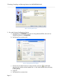
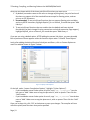
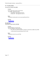
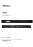
Creating, Compiling, and Running Code on the JHURSAEB/MaEvArM 3.1 Setting up your project: Note: If you’re on one of the Wyman 140 computers, DO NOT log in as “Station #x”, as this will cause compiler errors. Log in as “Guest” instead. 1. Open: Start>All Programs>Amtel AVR Tools>AVR Studio 4 2. Select New Project or Open a. For New Project, choose
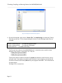
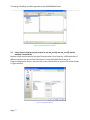
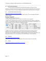
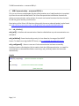
, set the project name and directory, tick “Create initial file” and “Create folder”, and press Finish (not Next) b. -‐ Save your project in a new project directory under C:\Users\Guest\RSA_2011\your_name\ for example: C:\ Users\Guest\RSA_2011\Whitcomb\My_Hello_World_Project c. See Figure 2 for a careen shot. Page | 4 3 Creating, Compiling, and Running Code on the JHURSAEB/MaEvArM Figure 2: Creating a New Project 3. Go under Project>Configuration Options a. Set frequency to 16000000 (if you are not using maevarmGEN.h, then set it to 200000) and device to atmega32U4 . b. See Figure 3 for a screen shot. Figure 3: Setting General Project Options c. Click on the “Include Directories” tab on the left, and press to add folder directory that contain custom header files – in this case the RSA library directory C:\RSA_library . d. Press OK e. See Figure 4 for a screen shot. Page | 5 3 Creating, Compiling, and Running Code on the JHURSAEB/MaEvArM Figure 4: Setting the Include Directory Options 4. On the left hand side, right click on “Source Files” and Add Existing to include the C library files that you will use. For the simple example in Section 3, the following header files are included: #include "maevarmGEN.h" // include the general header #include "maevarmUSB.h" // include the USB header #include <math.h> // include math library The first two lines reference the JHURSAEB libraries. Include the source code for these libraries in your project “source files” list. They are: C:/RSA_library/maevarmGEN.c C:/RSA_library/maevarmUSB.c The third line above includes the header file math.h that declares math functions such as sin() and cos(). If you want to use these math functions in your program, you need to tell the linker to link the math library libm.a into your program executable. This is described in the next section. See Figure 5 for a screen shot. Page | 6 3 Creating, Compiling, and Running Code on the JHURSAEB/MaEvArM Figure 5: Specifying Library Source Files 3.2 Linker Options: Setting up your project to use usb_printf() and usb_scanf() and the standard C math library Because a fully-‐functional printf and scanf functions take a lot of memory, AVR Studio offers 3 different versions of printf and scanf functions. To choose between the three, go to Project>Configuration Option, and then click on the Libraries button to get to the screen shown in Figure 6 below: Figure 6: Setting Link Libraries Page | 7 3 Creating, Compiling, and Running Code on the JHURSAEB/MaEvArM Here you can choose which of the three printf/scanf functions you want to use. 1. By default (no need to come to this menu or change anything here), the printf and scanf functions can support all of the standard formats except for floating points, and can print up to 255 characters. 2. Recommended: To use printf/scanf functions that can support floating point variables, and up to 65535 characters, highlight libprintf_flt.a or libscanf_flt.a and then press “Add Library-‐>” 3. To use printf/scanf functions that are smaller than the default and have minimal functionality (w/ basic integer & string conversions and only # conversion flags support), highlight libprintf_min.a or libscanf_min.a and then press “Add Library-‐>” If you are not using a default option, AFTER adding the custom link object, you must also add libm.a (make sure libm.a appears under the function object under “Link with These Objects” Lastly, after adding the desired function link objects and libm.a, click on Custom Options to reach the window shown in Figure 7 below: Figure 7: Specify Linker Options On the left, under “custom Compilation Options”, highlight “[Linker Options]”. -‐ If you’ve added a custom linker option for printf, copy “-Wl,-u,vfprintf” into the box next to “Add”. Make sure to copy the phrase as is, with no spaces. Then click the “Add” button. -‐ If you’ve added a custom linker option for scanf, copy “-Wl,-u,vfscanf” into the box next to “Add”. Make sure to copy the phrase as is, with no spaces. Then click the “Add” button. Once you’ve done this, click “OK” at the bottom to save your changes. The compiler will now utilize the printf/scanf functions that you’ve specified.
Page | 8 3 Creating, Compiling, and Running Code on the JHURSAEB/MaEvArM 3.3 Simple Project Source Code Example The following simple source file example can be compiled in a project. The project should include the following files: 1. This source file 2. The library source file maevarmGEN.c 3. The library source file maevarmUSB.c If you use math functions such as sin() and cos() from the math library, you will also need to specify the math library libm.a in the linker options. #include "maevarmGEN.h" // include the general header #include "maevarmUSB.h" // include the USB header #include <math.h> // include math library int main() { // begin of main int fooi=0; // declare int var fooi, initialize to 0 usb_initialize(); //initialize MaEvArM USB communication IO_mode(B0,OUTPUT); // config B0 pin as an OUTPUT while(1) // Loop forever { // begin of while loop // print to terminal usb_printf("Hello World fooi=%d \n", fooi); // increment variable fooi fooi = fooi + 1; delay_ms(500); // wait 500 ms IO_out(B0,HIGH); // set B0 pin to +5V delay_ms(500); // wait 500 ms IO_out(B0,LOW); // set B0 pin to 0V } // end of while loop } // end of main Page | 9 3 Creating, Compiling, and Running Code on the JHURSAEB/MaEvArM 3.4
Compiling, Downloading, and Running Your Project: 1. To build your project, press F7, , or “Build” under the Build drop-‐down menu 2. Open: Start>All Programs>Flip 3.4.3>Flip 3.4.3 3. Select the chip by clicking
and then choosing ATmega32U4 (Does not need to be repeated each time the program is started unless you change it) 4. Make sure the MaEvArM is connected and is in programming mode (press and hold the reset button until the green LED light up and then release, then the orange LED should remain lit to indicate that the device is in programming mode). 5. Open the connection by clicking Ctrl+U or >USB and then clicking “Open” 6. Press Ctrl+L or go under File and choose “Load Hex File” or choose from a list of Recent Hex Files a. When you compile your project, the Hex file containing the code will be generated under your project folder, in a subdirectory called default b. The name of the hex file will be something like this: C:\RSA_2011\Your_Name\Your_Project_Name\default\Your_Project_Name.hex 7. Press “Run” to download your program to the MaEvArm. 2. Making sure that the reset box is not ticked, click on “Start Application” to run your program If you don’t untick the reset box, you may find that the power to your MaEvArM may oscillate. Just unplug and plug in the device to fix. 8. If you want to make use of the reset button without sending the MaEvArM into programming mode, then just press the button briefly instead of holding it. 9. After you run the program, you can use the terminal emulator to connect to the serial USB output of your program. Disconnect the terminal emulator before recompiling and downloading new code. Page | 10 3 Creating, Compiling, and Running Code on the JHURSAEB/MaEvArM 3.5
Serial Terminal Emulators: In order for you to communicate with MaEvArM through the USB port on your computer, you need to download a program that will translate the digital data into characters on your screen. There are many free programs available online, and a few that are also good. 3.5.1
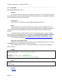
Terminal: (Recommended for this course) https://sites.google.com/site/terminalbpp/ A simple executable terminal with the ability to scan for port. This is the program we will be using in the class. Running “Terminal”: 1. Open: Start>All Programs>Terminal 2. Connect the MaEvArM to the PC and wait for the device to be recognized 3. Make sure the settings at the top match the image below (with the exception of COM Port number). The MaEvArM’s COM Port number will most likely be the highest numbered port. If it does not show up, then click “ReScan” to update the options. 4. Press “Connect” to connect to the device and begin communication 5. Make sure you press “Disconnect” to end communication before you disconnect the MaEvArM, put it into programming mode, or push the reset button on the MaEvArM, otherwise, the terminal will not be able to recognize the port until you press “Disconnect” and then reset the device. This is not necessary for the B4 RST Button on the JHURSAEB. 3.5.2
SerialChart: http://code.google.com/p/serialchart/ Optimized for data plotting. Chart formatting is done purely through text commands. 3.5.3
Termite: http://www.compuphase.com/software_termite.htm A light software with a simple UI. Page | 11 3 Creating, Compiling, and Running Code on the JHURSAEB/MaEvArM 3.6 General Tips, FAQ, and Troubleshooting “Do I have to create a new project or source code for each part of the lab?” No. What you can do is rename your main function to something else, such as main1 or part1, and then write a new main function for the portion of the lab you are currently working on. This way, you can keep all of your main functions in one source code. “How do I power the MaEvArM?” When the device is connected to the computer, it gets its power through the USB port, so unless you want to have the MaEvArM run while detached from the computer, you don’t need to provide external power to the MaEvArM. With the USB connected, you can access the +5V line through the pin V+. If you do want to power the MaEvArM in other ways, connect +5V to the V+ pin, and the ground to the GND pin. “When can I use hexadecimal numbers and when can I use decimal?” To the compiler, hexadecimal (number with prefix “0x”), decimal (just number), octal (number with prefix “0”), and in some cases, characters (characters with single quotation marks around them) are all the same and they are interchangeable. You should use whatever makes the code easier to read or is more intuitive to you. “How do I write a number in binary?” You can’t. Use a binary/decimal/hexadecimal converter and write it in decimal or hexadecimal or create your own header file containing text macros that will make the conversions for you. “I get a compiler error that says ‘unexpected EOF while looking for matching…’” This is most likely caused by one of the directories containing the project files having a character that will confuse the compiler. If you’re working in the Wyman lab, this most likely means that you’ve logged in as “Station #x”, and the symbol “#” is causing the error. Switch user to “guest”, or put the project files into a directory that won’t contain characters that will confuse the compiler. “I uploaded my program but it doesn’t do anything and stays in programming mode!” This is most likely caused by not loading a .hex file when you first start FLIP. If you do this, the FLIP loads a blank program onto the device, which leaves only the bootloader in the MaEvArM, causing it to constantly be in programming mode. “The timings of my functions are way off!” Under compiler options, check to make sure that the clock has been set to the correct frequency of 16000000 (2000000 if you don’t include maevarmGEN.h). “The terminal crashes when I try to communicate with the maevarm!” This may be caused by using the usb_initialize function and then setting the B4 pin to HIGH. Page | 12 4 Using this Manual: Name of Source Code and Header File 4 Using this Manual: Name of Source Code and Header File Function _Name Function’s declaration(argument1) Function Description of the function’s functionality. -‐ argument1 – description of argument + valid inputs for this argument (numerical value, if relevant) – descriptions if needed -‐ functions with many arguments may take different formats + Argument1, Argument2, ArgumentB, ArgumentC – equivalent to saying there are 4 possible arguments for this parameter: Argument1, Argument2, ArgumentB, ArgumentC. Prerequisites -‐ Minimal list of conditions that must be fulfilled before this function can be used successfully, excluding the inclusion of corresponding header and source code -‐ If a function does not have this, then it most likely means that aside from including the appropriate header and source code, there are no prerequisites to using the function properly Notes -‐ Special considerations that should be taken into account when using this function Tips, Tricks, and Common Errors -‐ General tips to help use the function, tricks to make using the function easier, and common errors that people make Sample A sample code that serves as an example of how to use this function.
Note that this section will generally not include preprocessor directives (e.g. #include), but will often contain prerequisites to using this function in a specific way.
If a function does not have sample code to go along with it, it is because the function is either too simple to need one (e.g. delay_ms), or it does not make sense to provide a sample code with just this function (setup functions usually fall into this category), and its use will most likely be shown in context under a related function sample code. Result If relevant/necessary, terminal results from above sample code will go here. See Also -‐ List of functions/appendices/sections that are closely related or may help in understanding this function
Page | 13 5 USB Communication – maevarmUSB.h/.c 5
USB Communication – maevarmUSB.h/.c This is a set of source code/header file that utilizes another set of code/header that is provided by UPenn for use with the MaEvArM. The UPenn files provide the initialization functions for setting up communication, and a number of transmit and receive functions that form the basis for our usb_printf and usb_scanf function. Descriptions of the UPenn USB functions (along with the source code and header) can be found at: https://alliance.seas.upenn.edu/~medesign/wiki/index.php/Guides/MaEvArM-‐usb 5.1 usb_initialize() usb_init() – Initializes usb communication. Must be called before any usb communication can take place. usb_initialize()– Same functionality as usb_init, but allows for the usage of the B4 RST button. For details on using the B4 RST Button, see 1.3 JHURSAEB Board B4 RST Button usb_configured() – Returns a non-‐zero if usb communication has been successfully initialized, returns a 0 otherwise. Can be used to check the USB communication, or to wait for communication to be established before continuing. usb_initialize() checks the connection automatically. Sample usb_init(); //initialize usb communication
while(!usb_configured()); //wait for initialization to complete
OR
usb_initialize(); //initialize usb communication w/ B4 RST
… Page | 14 //Rest of the code 5 USB Communication – maevarmUSB.h/.c 5.2
usb_printf() char usb_printf(const char * fmt, ...) Function The usb_printf function works like a standard printf function. The first argument should be a string, with format tags inserted as desired. There should be as many arguments following the first argument as there are format tags. Prerequisites -‐ usb_init() or usb_initialize() must be called beforehand (only once) Notes -‐ Certain special characters (of the \character variety) may not be displayed properly -‐ When communicating with the computer through the USB, you should have measures in place to account for delay between communication initialization and activation of your terminal -‐ By default, the usb_printf function cannot format floating points. In order to enable the full version (or the lighter version) of usb_printf, see Section 3.2 Linker Options: Setting up your project to use usb_printf() and usb_scanf() and the standard C math library on Page 7. -‐ See available formats here: http://www.cplusplus.com/reference/clibrary/cstdio/printf/ Tips, Tricks, and Common Errors -‐ Students often mistakenly use the function printf, as opposed to usb_printf. If nothing is displaying on the terminal, then this may be the reason. -‐ Don’t forget to utilize ‘\n’ or ‘\r’ to create line breaks, or the terminal may become difficult to read. Sample usb_initialize(); //initialize usb communication
while(!usb_configured()); //wait for initialization to complete
usb_printf("Ways to print 77:\n"); //no formatting
usb_printf("decimal: %d\n",77); //formatting using %d
usb_printf("4-‐digit hex: %04X\n", 77); //formatting and padding using %04X Result Ways to print 77
decimal: 77
4-‐digit hex: 004D See Also -‐ usb_init Page | 15 5 USB Communication – maevarmUSB.h/.c 5.3
usb_scanf char usb_printf(const char * fmt, ...) Function Works like the standard scanf function, except that it takes its input from the USB line. The first argument should be a string containing format tags, and the following arguments should contain pointers to the variables that you wish to store values into. Prerequisites -‐ usb_init or usb_initailize should be called beforehand. Notes -‐ This function looks for the carriage return (CR) to indicate the end of the string from the computer, so it is critical that you check “append CR” before sending data when using this function. -‐ This function will pause your program until data is available on the USB line. -‐ See available formats here: http://cplusplus.com/reference/clibrary/cstdio/scanf/ Tips, Tricks, and Common Errors -‐ MAKE SURE that “append CR” has been checked before sending data -‐ The dereference operator (&) is needed to retrieve the pointer for most types of variables, but because arrays naturally use pointers, they don’t require the reference operator Sample int number; //initialize int char street[256]; //initialize char array //store first batch of characters as a decimal into number (& needed) //store second batch of characters as a string into street (& not needed) usb_scanf("%d %s",&number,street); //echo input usb_printf("You entered: %d %s",number,street); Result If you enter:
3400 Charles St.
The program will return:
You entered: 3400 Charles
“St.” is tossed because the program was not told to store it. See Also -‐ usb_init Page | 16 6 General MaEvArM Functions -‐ maevarmGEN.h/.c 6
General MaEvArM Functions -‐ maevarmGEN.h/.c This set of header/source code provide functions that are made for general usage of the MaEvArM, that is, they do not fall under any particular functional modules, consisting of functions that manipulate digital inputs/outputs of the pins and delay functions. It is highly recommended that you include this code for all of your projects, as it also contains an initialization sequence that allows the MaEvArM to operate at 16 MHz (without the initialization it will operate at 2 MHz). 6.1 delay_ms() void delay_ms(int DELAY_TIME) Function The delay_ms function causes the program to pause for the desired number of milliseconds. -‐DELAY_TIME – Desired number of milliseconds + 0~65535 Notes -‐ Limit is set by the size of the argument (65535 ms), but accuracy may be lost with larger numbers -‐ Use this instead of _delay_ms() because _delay_ms becomes inaccurate for delay times over 262.14 ms/F_CPU in MHz 6.2 delay_us() #define delay_us(DELAY_TIME) Function The delay_us function causes the program to pause for the desired number of microseconds. -‐DELAY_TIME – Desired number of microseconds + 0~65535 Notes -‐ This “function” is simply a text macro, and is equivalent to _delay_us -‐ delay_us becomes inaccurate for delay times over 768 ms/F_CPU in MHz -‐ using delay_us is not recommended for generating waveforms with periods less than 100 us because instructions in between will add significant time to the period Page | 17 6 General MaEvArM Functions -‐ maevarmGEN.h/.c 6.3
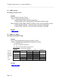
IO_mode() char IO_mode([PIN NAME], unsigned char config) Function Sets one or more of the I/O pins to function as digital input or output. SINGLE PIN MANIPULATION: -‐ [PIN NAME] – consists of 2 arguments {char let, char num}, but macros have been set up to accept pin name (e.g. B7, F0) = pin# combination available X \ # 0 1 2 3 4 5 6 7 B C D E F -‐ config – Desired configuration + INPUT (0) + OUTPUT (1) MULTIPLE PIN MANIPULATION: -‐ [PIN NAME] – For multiple pin manipulation, insert one of the predefined names for groups of pins + ENTIREB, ENTIRED – pins B7~B0 or D7~D0 + UPPERB, UPPERD, UPPERF – pins B7~B4, D7~D4, or F7~F4 + LOWERB, LOWERD – pins B3~B0 or D3~D0 -‐ config – Desired multiple pin configuration. Each binary digit corresponds to a pin, with the leftmost binary digit corresponding to highest pin number. For example, setting UPPERB to 0xC (binary 1100) sets pins B7 and B6 to OUTPUT (1) and pins B5 and B4 to INPUT (0) Notes -‐ By default, the pins are set to input -‐ Every I/O pin is connected to one or more functional units in the chip, and many functions require the I/O mode to be set to either OUTPUT or INPUT to work. For example, to generate a waveform using Timer1 on the Output Compare 1 B pin (B6), pin B6 must be set to output beforehand. Sample IO_mode(B0,OUTPUT); //sets pin B0 to output IO_mode(LOWERD,0xA); //0xA = binary 1010: sets pin D0 and D2 to input and //D1 and D3 to output See Also -‐ IO_out -‐ IO_read Page | 18 6 General MaEvArM Functions -‐ maevarmGEN.h/.c 6.4
IO_out() char IO_out([PIN NAME], unsigned char config) Function Outputs a logic level on one or more of the I/O pins. SINGLE PIN MANIPULATION: -‐ [PIN NAME] – consists of 2 arguments {char let, char num}, but macros have been set up to accept pin name (e.g. B7, F0) = pin# combination available X \ # 0 1 2 3 4 5 6 7 B C D E F -‐ config – Desired configuration + LOW (0) + HIGH (1) MULTIPLE PIN MANIPULATION: -‐ [PIN NAME] – For multiple pin manipulation, insert one of the predefined names for groups of pins + ENTIREB, ENTIRED – pins B7~B0 or D7~D0 + UPPERB, UPPERD, UPPERF – pins B7~B4, D7~D4, or F7~F4 + LOWERB, LOWERD – pins B3~B0 or D3~D0 -‐ config – Desired multiple pin configuration. Each binary digit corresponds to a pin, with the leftmost binary digit corresponding to highest pin number. For example, setting UPPERB to 0xC (binary 1100) sets pins B7 and B6 to HIGH (1) and pins B5 and B4 to LOW (0) Notes -‐ To produce digital output, the pin should be set to OUTPUT using IO_mode -‐ If the pin is set to INPUT, then this function will cause the pin to be pulled up if it is set HIGH, and will cause it to act as a regular input pin if it is set LOW Sample //single pin manipulation IO_mode(B4,OUTPUT); //set pin B4 to output IO_out(B4,HIGH); //output a logic 1 on B4 //multiple pin manipulation IO_mode(UPPERD,0xF); //0xF = binary 1111: sets pin D7~D4 to output //0xA = binary 1010: sets pin D4 and D6 to input and //5 and D7 to output IO_out(UPPERD,0xA); See Also -‐ IO_mode Page | 19 6 General MaEvArM Functions -‐ maevarmGEN.h/.c 6.5
IO_read() char IO_read([PIN NAME]) Function Returns the logic level detected on one of the I/O pins -‐ [PIN NAME] – consists of 2 arguments {char let, char num}, but macros have been set up to accept pin name (e.g. B7, F0) = pin# combination available X \ # 0 1 2 3 4 5 6 7 B C D E F Notes -‐ The pin should be set to INPUT using IO_mode and the logic level written to the pin using IO_out should be LOW before using this function. Sample IO_mode(D2,INPUT); //set pin D2 to input char switch = 0; //allocate variable switch = IO_read(D2); //store D2 reading into switch See Also -‐ IO_mode Page | 20 7 Analog to Digital Converter -‐ maevarmADC.h/.c 7
Analog to Digital Converter -‐ maevarmADC.h/.c ATmega32U4 contains a 10-‐bit analog to digital converter (ADC). The maximum value can be set to internal +5V, internal +2.56V, or an external voltage on the AR (analog reference) pin. The minimum is always GND. There are 12 ADC channels (11 ADC pins and 1 temperature sensor). ADC pin # and their corresponding port pins: 0 -‐ F0 1 -‐ F1 4 -‐ F4 5 -‐ F5 6 -‐ F6 7 -‐ F7 8 -‐ D4 9 -‐ D6 10 -‐ D7 11 -‐ B4 12 -‐ B5 13 -‐ B6 14 -‐ Temperature Sensor 7.1 ADC_enable() char ADC_enable() 7.2
Function Enables the ADC module. Notes -‐ Must be called before AD conversion can occur. See Also -‐ ADC_disable -‐ ADC_read -‐ ADC_set_CLK -‐ ADC_set_AREF -‐ ADC_set_channel ADC_set_AREF() char ADC_set_AREF(char ADC_AREF_SETTING) Function Sets the reference (maximum) voltage for ADC. -‐ ADC_AREF_SETTING – desired reference voltage source + AREF_Ext – AR pin voltage + AREF_Vcc – Internal +5V + AREF_256 – Internal +2.56 V Notes -‐ By default, the reference voltage is set to the AR pin. See Also -‐ ADC_enable -‐ ADC_set_channel Page | 21 7 Analog to Digital Converter -‐ maevarmADC.h/.c 7.3
ADC_set_CLK() char ADC_set_CLK(unsigned char ADC_CLK_SETTING) Function Sets the clock source for ADC. The clock speed determines the resolution and speed of A/D conversions. -‐ ADC_CLK_SETTING – Desired prescalar clock (prescaled from system clock) + ADC_CLK2, ADC_CLK4, ADC_CLK8, ADC_CLK16, ADC_CLK32, ADC_CLK64, ADC_CLK128 – number determines prescaling factor Notes -‐ The clock speed should be between 50~200kHz for the best resolution -‐ By default the clock is set to system clock/2 See Also -‐ ADC_enable 7.4 ADC_set_channel() char ADC_set_channel(unsigned char ADC_CHANNEL_SETTING) Function Sets ADC channel to read from. -‐ ADC_CHANNEL_SETTING – Desired ADC channel + 0-‐1, 4-‐14 ADC channel and their corresponding port pins: 0 -‐ F0 1 -‐ F1 4 -‐ F4 5 -‐ F5 6 -‐ F6 7 -‐ F7 8 -‐ D4 9 -‐ D6 10 -‐ D7 11 -‐ B4 12 -‐ B5 13 -‐ B6 14 -‐ Temperature Sensor Notes -‐ By default, ADC channel 0 (F0) is selected. Tips, Tricks, and Common Errors -‐ If you’re going to be reading consecutively from one channel, then there is no need to call this function every time; you only need to call this when you wish to change the channel. Sample ADC_set_channel(12); //set to channel 12 (B5) ADC_set_channel(0); //set to channel 0 (F0) See Also -‐ ADC_read -‐ ADC_set_AREF Page | 22 7 Analog to Digital Converter -‐ maevarmADC.h/.c 7.5
ADC_disable_digital() char ADC_disable_digital(unsigned char ADC_DIGI_PIN) 7.6
Function Disables digital input on an ADC pin. -‐ ADC_DIGI_PIN – Desired pin-‐connected channel number + 0-‐1, 4-‐13 ADC channel and their corresponding port pins: 0 -‐ F0 1 -‐ F1 4 -‐ F4 5 -‐ F5 8 -‐ D4 9 -‐ D6 10 -‐ D7 11 -‐ B4 6 -‐ F6 12 -‐ B5 7 -‐ F7 13 -‐ B6 Notes -‐ Call to disable the digital input buffer on a port pin for saving power. See Also -‐ IO_mode -‐ ADC_set_channel ADC_justify() char ADC_justify(char ADC_JUST_SETTING) Function Justifies the results of AD conversion to the left or to the right. In layman's terms, within the 16-‐bits (2 registers) containing the 10 bit ADC data, the data is either aligned to the left or to the right. -‐ ADC_JUST_SETTING – Desired justification side + ADC_LEFT, ADC_RIGHT – Left or right justification Notes -‐ If using ADC_read to obtain all 10 bits, then justify right. -‐ If using ADC_read8 to obtain only the most significant 8 bits, then justify left. -‐ By default, the data is justified right See Also -‐ ADC_read -‐ ADC_readH Page | 23 7 Analog to Digital Converter -‐ maevarmADC.h/.c 7.7
ADC_read() unsigned int ADC_read() Function Reads and returns the 10-‐bit ADC value from the selected channel. Prerequisites -‐ ADC must be enabled using ADC_enable Notes -‐ The 10 bits of data should be right justified before using this function, or you will get a value that is multiplied by 2^6 (6 extra bits to the side) -‐ To read from a specific channel, you must select the channel using ADC_set_channel -‐ To obtain the best resolution, ADC clock speed must be set using ADC_set_CLK -‐ To set reference voltage to a specific value, reference must be selected using ADC_set_AREF Sample int value = 0; //initialize variable ADC_enable(); //enable ADC system ADC_set_CLK(ADC_CLK8); //set ADC CLK to 1 MHz/8 = 125KHz ADC_set_channel(4); //set ADC channel to 4 (F4) value = ADC_read(); //read and store value in variable See Also -‐ ADC_readH -‐ ADC_enable -‐ ADC_set_channel Page | 24 7 Analog to Digital Converter -‐ maevarmADC.h/.c 7.8
ADC_readH() unsigned char ADC_readH() Function Reads and returns the most significant byte of the 2 data registers. Prerequisites -‐ ADC must be enabled using ADC_enable Notes -‐ To return an 8-‐bit data, the data should be left justified using ADC_justify, otherwise this function will return the 2 most significant bits -‐ To read from a specific channel, you must select the channel using ADC_set_channel -‐ To obtain the best resolution, ADC clock speed must be set using ADC_set_CLK -‐ To set reference voltage to a specific value, reference must be selected using ADC_set_AREF Tips, Tricks, and Common Errors -‐ If 10 bits of data is unnecessary, then use this function after left justifying to obtain 8 bits of data. Sample char value = 0; //initialize variable ADC_enable(); //enable ADC system ADC_set_CLK(ADC_CLK8); //set ADC CLK to 1 MHz/8 = 125KHz ADC_set_channel(4); //set ADC channel to 4 (F4) ADC_justify(ADC_LEFT); //left justify data value = ADC_readH(); //read and store value in variable See Also -‐ ADC_read -‐ ADC_justify 7.9
ADC_disable() char ADC_disable() again.
Function Disables the ADC system. Notes -‐ Once this function is called, no A/D conversions can occur until ADC_enable is called Page | 25 8 Serial Peripheral Interface -‐ maevarmSPI.h/.c 8
Serial Peripheral Interface -‐ maevarmSPI.h/.c Serial Peripheral Interface is a serial communication protocol that allows a master device to communicate with a slave device using 4 lines. The 4 SPI pins on the MaEvArM are: B0 = SS – Slave Select B1 = SCK – Serial Clock B2 = MOSI – Master Out Slave In B3 = MISO – Master In Slave Out The ATmega32U4 can be programmed to act as a master or a slave. Even when SPI is enabled, the 4 pins will act like regular I/O pins when data isn’t being transferred. This means that the user must correctly initialize the port pins to be in the correct mode and have the appropriate digital output. The initialization functions will do this for you, but you must make sure that you don’t change the modes or the outputs of the pins in a way that will interfere with the SPI communication. Communication becomes active when the master brings the SS line low. The slave will communicate and receive data in sync with the SCK pulses provided by the master. 8.1
SPI_MasterInit() char SPI_MasterInit() Function Initializes the SPI module as the master. Notes -‐ B0 (SS), B1 (SCK), and B2 (MOSI) will be set to OUTPUT while B3 (MISO) is set to INPUT. -‐ All four pins are set to HIGH, meaning active high for B0~B2, and pullup for MISO See Also -‐ SPI_data_order -‐ SPI_SCK_set -‐ SS_low -‐ SS_high Page | 26 8 Serial Peripheral Interface -‐ maevarmSPI.h/.c 8.2
SPI_data_order() char SPI_data_order(char SPI_DORD) Function Sets the data order of SPI communication. -‐ SPI_DORD – Desired data order + LSB_FIRST – Least significant bit first + MSB_FIRST – Most significant bit first Notes -‐ By default, the data order is set to most significant bit first See Also -‐ SPI_MasterInit SPI_SCK_set char SPI_SCK_set(char SPI_SCK_SETTING) Function Sets the frequency of the SPI clock. -‐ SPI_SCK_SETTING – Desired prescalar + SPI_SCK2, SPI_SCK4, SPI_SCK8, SPI_SCK16, SPI_SCK32, SPI_SCK64, SPI_SCK128 – number determines prescaling of the CPU clock Notes -‐ By default, the clock is set to CPU/4 See Also -‐ SPI_MasterInit Page | 27 8 Serial Peripheral Interface -‐ maevarmSPI.h/.c 8.3
SS_low() char SS_low() Function Brings SS (pin B0) line low, initiating SPI communication. Prerequisites -‐ The MaEvArM should be initialized to act as the SPI master Notes -‐ This is functionally equivalent to calling IO_out(B0,LOW) -‐ Must be called before sending or receiving data if the MaEvArM is the master, and should be called only if MaEvArM is the master. See Also -‐ SS_high -‐ SPI_MasterInit 8.4 SS_high() char SS_high() Function Pulls SS (pin B0) line high, terminating SPI communication. Prerequisites -‐ The MaEvArM should be initialized to act as the SPI master Notes -‐ This is functionally equivalent to calling IO_out(B0,HIGH) -‐ Must be called after finishing sending or receiving data if the MaEvArM is the master, and should be called only if MaEvArM is the master. See Also -‐ SS_low -‐ SPI_MasterInit Page | 28 8 Serial Peripheral Interface -‐ maevarmSPI.h/.c 8.5
SPI_send() char SPI_send(unsigned char SPI_DATA) Function Sends a byte of data through SPI line. -‐ SPI_DATA – Byte to transfer + 0x00~0xFF Prerequisites -‐ SPI should be initialized to act as a master or a slave -‐ As a master, the SS line should be brought low using SS_low before sending and receiving data. Notes -‐ Will pause the program until it is able to send data -‐ As a slave, it is strongly recommended that the software check to see if the master has brought the SS line low before calling this function, as calling this beforehand will make the program wait indefinitely until it can send data. Sample SPI_MasterInit(); //Initialize SPI as master //Leave SPI_CLK to 1/4 of CPU clock //Leave data order at MSB first SS_low(); //bring SS line low to start SPI_send(0x88); //send byte 0x88 SPI_send(0xC3); //send byte 0xC3 SS_high(); //pull SS line high to end See Also -‐ SPI_MasterInit Page | 29 8 Serial Peripheral Interface -‐ maevarmSPI.h/.c 8.6
SPI_read() unsigned char SPI_read() Function Receives and returns a byte of data from the SPI line. Prerequisites -‐ SPI should be initialized to act as a master or a slave -‐ As a master, the SS line should be brought low using SS_low before sending and receiving data. Notes -‐ Works by sending the byte 0x00 while receiving data, and will pause the program until it is able to send data -‐ As a slave, it is strongly recommended that the software check to see if the master has brought the SS line low before calling this function, as calling this beforehand will make the program wait indefinitely until it can send data. Sample char databyte = 0; //initialize variable SPI_MasterInit(); //Initialize SPI as master //Leave SPI_CLK to 1/4 of CPU clock //Leave data order at MSB first SS_low(); //bring SS line low to start databyte = SPI_read(); //read and store byte in variable SS_high(); //pull SS line high to end See Also -‐ SPI_MasterInit Page | 30 9 8-‐Bit Timer/Counter 0 – maevarmTMR0.h/.c 9
8-‐Bit Timer/Counter 0 – maevarmTMR0.h/.c Timers/Counters are modules that can count up or down at a steady rate. They can be used to measure the time between two events, create a waveform, or to keep track of time. The counting frequency of each timer is determined by the prescaled timer that the user assigns to that timer module, and this is used to calculate the relationship between the number of counts and the time that has elapsed. Timer 0 is an 8-‐bit counter, meaning that they count from a value of 0 to 255. For 16-‐bit counters, use time/counter 1 or 3 (atmega32U4 also has timer4, but it does not have a library implementation at this time). Timer 0 interacts with the following I/O pins: B7 = Timer0 Output Compare A (OC0A) D0 = Timer0 Output Compare B (OC0B) D7 = Timer0 Counter Source (T0) Terminology: TOP – value that the counter counts to before overflowing BOTTOM – value of 0 MAX – highest possible value, in this case, 255 OCRX – value stored in Output Compare Register X by function TMR0_X_value Page | 31 9 8-‐Bit Timer/Counter 0 – maevarmTMR0.h/.c 9.1
TMR0_source() char TMR0_source(unsigned char TMR0_SOURCE) Function Selects the clock source for Timer 0. -‐ TMR0_SOURCE – The source clock for Timer 0 + TMR0_SOURCE_NONE – No clock, stops timer + TMR0_SOURCE_CLK1, TMR0_SOURCE_CLK8, TMR0_SOURCE_CLK64, TMR0_SOURCE_CLK256, TMR0_SOURCE_CLK1024 – System clock prescaled by number + TMR0_SOURCE_EXTFALL – External pin (D6), counting on falling edge + TMR0_SOURCE_EXTRISE – External pin (D6), counting on rising edge Notes -‐ By default, the timer is not connected to a source clock (SOURCE_NONE), so this function must be called before using Timer0. Other Timer0 setup functions, however, can be called beforehand. See Also -‐ TMR0_set_mode 9.2 TMR0_set_mode() char TMR0_set_mode(unsigned char TMR0_MODE) Function Sets the counting/waveform generation mode for Timer0. -‐ TMR0_MODE – The desired counting/waveform generation setting + TMR0_ZZZ_YYY ZZZ -‐ type of waveform generated YYY -‐ TOP, the value counter will count up to = combination available NORMAL CTC PCPWM FPWM Only ZZZ MAX OCRA OCRA = value stored in OCR0A Notes -‐ By default, Timer0 is set to NORMAL operations Sample TMR0_set_mode(TMR0_NORMAL); //sets timer1 mode to normal TMR0_set_mode(TMR0_PCPWM_MAX); //sets mode to PCPWM with TOP value of 0xFF TMR0_set_mode(TMR0_CTC_OCRA); //sets mode to CTC with TOP value of OCRA Page | 32 9 8-‐Bit Timer/Counter 0 – maevarmTMR0.h/.c 9.3
See Also -‐ TMR0_source -‐ TMR0_set_mode TMR0_X_mode() //X = A, or B char TMR0_X_mode(unsigned char X_MODE) Function Sets the behavior of the output on the Output Compare pins (OC0A – B7, OC0B – D0). The exact effect depends on the type of waveform set by TMR0_set_mode -‐ X_MODE – The desired pin output behavior + TMR0_PIN_NORMAL, TMR0_PIN_TOGGLE, TMR0_PIN_CLEAR, TMR0_PIN_SET All waveforms: NORMAL – Pin is disconnected and acts as regular port pin Normal mode: TOGGLE – Pin is toggled on compare match CLEAR – Pin is cleared on compare match SET – Pin is set on compare match CTC mode: TOGGLE– Pin is toggled on compare match CLEAR – Pin is cleared on compare match SET – Pin is set on compare match FPWM mode: TOGGLE – For A only, if TOP is OCRA, toggles pin output on compare match. OC0B acts as regular port pin. CLEAR – Clears pin on compare match, set pin at TOP SET – Set pin on compare match, clear pin at TOP PCPWM: TOGGLE – For A only, if TOP is OCRA, toggles pin output on compare match (both rising and falling). OC0B acts as regular port pin. CLEAR – Clears pin on rising match, sets on falling match SET – Sets pin on rising match, clears on falling match Prerequisites -‐ In order to use this function to generate a PWM signal, the appropriate mode must be selected using TMR0_set_mode and the timer should set to run using TMR0_source. -‐ To generate an output, the corresponding pin must be set to output using IO_mode Notes -‐ For PWM mode, setting the mode to CLEAR makes the comparison value proportional to duty cycle, and setting the mode to SET inverts the signal. See atmega32U4 manual section 13.6 for more details. Page | 33 9 8-‐Bit Timer/Counter 0 – maevarmTMR0.h/.c -‐ The TOGGLE modes can be used to create a square wave Sample TMR0_set_mode(TMR0_PCPWM_MAX); //sets mode to PCPWM with TOP value of 0xFF TMR0_A_value(128); //sets A comparison value to 128 TMR0_B_value(200); //sets B comparison value to 200 TMR0_A_mode(TMR0_PIN_SET); //set inverted PWM on pin OC0A TMR0_B_mode(TMR0_PIN_CLEAR); //set PWM on pin OC0B TMR0_source(TMR0_SOURCE_CLK1); //connect Timer0 to a clock and begin PWM 9.4
See Also -‐ TMR0_set_mode -‐ TMR0_source TMR0_X_value() //X = A or B char TMR0_X_value(unsigned char COUNTER_VALUE) Function Stores the comparison value for Timer0’s output compare units -‐ COUNTER_VALUE – desired comparison value + 0x00~0xFF Sample TMR1_A_value(0x0F); //set A comparison value to 15 TMR1_B_value(0xFF); //set B comparison value to 255 See Also -‐ TMR0_X_mode Page | 34 10 16-‐Bit Timer/Counter 1 – maevarmTMR1.h/.c 10 16-‐Bit Timer/Counter 1 – maevarmTMR1.h/.c Timers/Counters are modules that can count up or down at a steady rate. They can be used to measure the time between two events, create a waveform, or to keep track of time. The counting frequency of each timer is determined by the prescaled timer that the user assigns to that timer module, and this is used to calculate the relationship between the number of counts and the time that has elapsed. Timer1 is a 16-‐bit timer, while the atmega32U4 has an 8-‐bit CPU. This means that the CPU must take a special procedure to interact with registers that contain 16-‐bits, during which interrupts will lead to errors. Therefore, all functions that interact with the 16-‐bit registers will disable interrupts before the read/write operation, and will enable them once the operation is done. The functionality of Timer1 is nearly identical to that of Timer3 Timer 1 interacts with the following I/O pins: B5 = Timer1 Output Compare A (OC1A) B6 = Timer1 Output Compare B (OC1B) B7 = Timer1 Output Compare C (OC1C) D4 = Timer1 Input Compare Pin (ICP1) D6 = Timer1 Counter Source (T1) Terminology: TOP – value that the counter counts to before overflowing BOTTOM – value of 0 MAX – highest possible value, in this case, 65535 ICR – value stored in Input Compare Register from input compare. OCRX – value stored in Output Compare Register X by function TMR1_X_value Page | 35 10 16-‐Bit Timer/Counter 1 – maevarmTMR1.h/.c 10.1 TMR1_source() char TMR1_source(char source) Function Selects the clock source for Timer 1. -‐ source – The source clock for Timer 1 + TMR1_SOURCE_NONE – No clock, stops timer + TMR1_SOURCE_CLK1, TMR1_SOURCE_CLK8, TMR1_SOURCE_CLK64, TMR1_SOURCE_CLK256, TMR1_SOURCE_CLK1024 – System clock prescaled by number + TMR1_SOURCE_EXTFALL – External pin (D6), counting on falling edge + TMR1_SOURCE_EXTRISE – External pin (D6), counting on rising edge Notes -‐ By default, the timer is not connected to a source clock (SOURCE_NONE), so this function must be called before using Timer1. Other Timer1 setup functions, however, can be called beforehand. See Also -‐ TMR1_set_mode -‐ TMR1_IC_read Page | 36 10 16-‐Bit Timer/Counter 1 – maevarmTMR1.h/.c 10.2 TMR1_set_mode() char TMR1_set_mode(char setting) Function Sets the counting/waveform generation mode for Timer1. -‐ setting – The desired counting/waveform generation setting + TMR1_ZZZ_YYY ZZZ -‐ type of waveform generated YYY -‐ TOP, the value counter will count up to = combination available NORMAL CTC PCPWM FPWM PCFPWM Only ZZZ 8 (0xFF) 9 (0x1FF) 10 (0x3FF) ICR OCRA OCRA = value stored in OCR1A ICR = value stored in ICR1 Notes -‐ By default, Timer1 is set to NORMAL operation -‐ Choosing a mode with ICR as the TOP will disable Input Capturing Sample TMR1_set_mode(TMR1_NORMAL); //sets timer1 mode to normal TMR1_set_mode(TMR1_PCPWM_8); //sets mode to PCPWM with TOP value of 0xFF TMR1_set_mode(TMR1_CTC_ICR); //sets mode to CTC with TOP value of ICR See Also -‐ TMR1_source -‐ TMR1_X_mode Page | 37 10 16-‐Bit Timer/Counter 1 – maevarmTMR1.h/.c 10.3 TMR1_X_mode() //X = A, B, or C char TMR1_X_mode(unsigned char setting) Function Sets the behavior of the output on the Output Compare pins (OC1A -‐ B5, OC1B -‐ B6, OC1C -‐ B7). The exact effect depends on the type of waveform set by TMR1_set_mode -‐ setting – The desired pin output behavior + TMR1_PIN_NORMAL, TMR1_PIN_TOGGLE, TMR1_PIN_CLEAR, TMR1_PIN_SET All waveforms: NORMAL -‐ pin is disconnected and acts as regular port pin CTC/Normal (from X_mode) mode: TOGGLE -‐ pin is toggled on compare match CLEAR -‐ pin is cleared on compare match SET -‐ pin is set on compare match FPWM mode: TOGGLE -‐ For A only, if TOP is ICR or OCRA, toggles pin output on compare match. Otherwise normal pin operation. CLEAR -‐ Clears pin on compare match, set pin at TOP SET -‐ Set pin on compare match, clear pin at TOP PCPWM/PFCPWM: TOGGLE -‐ For A only, if TOP is ICR or OCRA, toggles pin output on compare match (both rising and falling). Otherwise normal pin operation. CLEAR -‐ Clears pin on rising match, sets on falling match SET -‐ Sets pin on rising match, clears on falling match Prerequisites -‐ In order to use this function to generate a PWM signal, the appropriate mode must be selected using TMR1_set_mode and the timer should set to run using TMR1_source. -‐ To generate an output, the corresponding pin must be set to output using IO_mode. Notes -‐ For PWM mode, setting the mode to CLEAR makes the comparison value proportional to duty cycle, and setting the mode to SET inverts the signal. See atmega32U4 manual section 14.8 for more details. -‐ The TOGGLE modes can be used to create a square wave Sample TMR1_set_mode(TMR1_PCPWM_8); //sets mode to PCPWM with TOP value of 0xFF TMR1_A_value(128); //sets A comparison value to 128 TMR1_B_value(200); //sets B comparison value to 200 TMR1_A_mode(TMR1_PIN_SET); //set inverted PWM on pin OC1A TMR1_B_mode(TMR1_PIN_CLEAR); //set PWM on pin OC1B TMR1_source(TMR1_SOURCE_CLK1); //connect Timer1 to a clock and begin PWM See Also Page | 38 10 16-‐Bit Timer/Counter 1 – maevarmTMR1.h/.c -‐ TMR1_set_mode -‐ TMR1_source 10.4 TMR1_X_value() //X = A, B, or C char TMR1_A_value(unsigned int COUNTER_VALUE) Function Stores the comparison value for Timer1’s output compare units -‐ COUNTER_VALUE – desired comparison value + 0x0000~0xFFFF Notes -‐ This function involves writing to a 16 bit register, so interrupts are disabled during a part of the function. Sample TMR1_A_value(0x0FFF); //set A comparison value to 4095 TMR1_B_value(65500); //set B comparison value to 65500 TMR1_C_value(20); //set C comparison value to 20 See Also -‐ TMR1_X_mode Page | 39 10 16-‐Bit Timer/Counter 1 – maevarmTMR1.h/.c 10.5 TMR1_IC_noise_canceller() char TMR1_IC_noise_canceller(char setting) Function Activates or deactivates the built-‐in Input Capture noise canceller. -‐ setting – desired Noise Cancel setting + TMR1_NC_ON – noise canceller on + TMR1_NC_OFF – noise canceller off Notes -‐ The noise canceller works by sampling the pin repeatedly and making sure that the pin remains changed for 4 counts in a row before storing the count value. This causes the stored counter value to be 4 counts greater than the count corresponding to the event. Tips, Tricks, and Common Errors -‐ If you’re using the counter to store the duration (difference between two events), the 4 counts of difference won’t matter as long as the noise canceller is either on or off for when both events occur. See Also -‐ TMR1_IC_read 10.6 TMR1_IC_edge_select() char TMR1_IC_edge_select(char setting) Function Determines whether the Input Capture Unit is triggered by a rising edge or a falling edge. In other words, sets the definition of an “event”. -‐ setting – desired edge selection + TMR1_ES_RISING – Rising edge select + TMR1_ES_FALLING – Falling edge select Notes -‐ By default, the IC unit is set to be triggered by a falling edge See Also -‐ TMR1_IC_read Page | 40 10 16-‐Bit Timer/Counter 1 – maevarmTMR1.h/.c 10.7 TMR1_IC_read() unsigned int TMR1_IC_read() Function Waits for a flag to be set by an event on the Input Capture pin (ICP1 – D4) and returns the counter value at the event. After reading the value, the function clears the flag. Prerequisites -‐ ICP1 (pin D4) should be set to input before calling this function. -‐ Timer1 clock must be set to run using the TMR1_source functions. -‐ The TOP of the Output Compare unit set by TMR1_set_mode must not equal ICP Notes -‐ This function waits until the flag is set and returns the store value, but it does not discriminate as to when this event occurred. If an event had occurred before calling this function and the flag is set, it will immediately return the stored counter value. Tips, Tricks, and Common Errors -‐ To guarantee returning of a count value of a future event, call the function TMR1_IC_clear right before calling this function. Sample int value = 0; //initialize variable TMR1_edge_select(TMR1_ES_RISING); //select rising edge TMR1_IC_clear(); //clear IC flag value = TMR1_IC_read(); //read and store the value See Also -‐ TMR1_source -‐ TMR1_IC_clear -‐ TMR1_IC_edge_select -‐ TMR1_IC_noise_canceller Page | 41 10 16-‐Bit Timer/Counter 1 – maevarmTMR1.h/.c 10.8 TMR1_pulsein() unsigned int TMR1_pulsein() Function Waits for a square pulse to occur on the Input Compare Pin 1 (ICP1), and returns the length of the pulse in term of timer counts. Prerequisites -‐ ICP1 (pin D4) should be set to input before calling this function. -‐ Timer1 clock must be set to run using the TMR1_source functions. -‐ The TOP of the Output Compare unit set by TMR1_set_mode must not equal ICP. Notes -‐ This function clears the event flag before reading the rising edge, and therefore it is not necessary to clear the flag before calling this function. -‐ The current version of this function only accounts for the possibility of a single overflow, so if the duration of the pulse is large enough to cause the counter to overflow twice, then the returned value will be inaccurate. Tips, Tricks, and Common Errors -‐ If Timer1 source is set to be 1 MHz (no prescaling if system clock is 1MHz, divide by 8 if system clock is 8 MHz, etc.), then the function returns the duration of the pulse in microseconds. Sample TMR1_source(TMR1_SOURCE_CLK1); //set clock source to system clock mode_D(4, input); //set pin D4 to input int duration = 0; //initialize variable duration = TMR1_pulsein(); //measure pulse duration and store See Also -‐ TMR1_IC_read -‐ TMR1_source Page | 42 10 16-‐Bit Timer/Counter 1 – maevarmTMR1.h/.c 10.9 TMR1_IC_clear() char TMR1_IC_clear() Function Clears the Input Capture unit event flag. Notes -‐ This function clears the flag that indicates that an event has occurred, but does not erase the count value that was stored when the event occurred. See Also -‐ TMR1_IC_read Page | 43 11 16-‐Bit Timer/Counter 3 – maevarmTMR3.h/.c 11 16-‐Bit Timer/Counter 3 – maevarmTMR3.h/.c Timer3 is a 16-‐bit timer that is nearly identical in function to that of Timer 1. Functions and arguments are provided below, but for details on their use, refer to their Timer 1 counterparts in the previous section. Note that although Timer 3 has functions and registers to utilize output compare B and C, the pins to interact with them do not exist. The functions have been provided, however, because they can likely be used to generate interrupts. Timer 3 interacts with the following I/O pins: C6 = Timer3 Output Compare A (OC3A) C7 = Timer3 Input Compare Pin (ICP3) D6 = Timer1 Counter Source (T1) Terminology: TOP – value that the counter counts to before overflowing BOTTOM – value of 0 MAX – highest possible value, in this case, 65535 ICR – value stored in Input Compare Register from input compare. OCRX – value stored in Output Compare Register X by function TMR3_X_value Page | 44 11 16-‐Bit Timer/Counter 3 – maevarmTMR3.h/.c 11.1 TMR3_source() char TMR3_source(char source) Function Selects the clock source for Timer 3. -‐ source – The source clock for Timer 3 + TMR3_SOURCE_NONE – No clock, stops timer + TMR3_SOURCE_CLK1, TMR3_SOURCE_CLK8, TMR3_SOURCE_CLK64, TMR3_SOURCE_CLK256, TMR3_SOURCE_CLK1024 – System clock prescaled by number + TMR3_SOURCE_EXTFALL – External pin (D6), counting on falling edge + TMR3_SOURCE_EXTRISE – External pin (D6), counting on rising edge See Also -‐ TMR1_source 11.2 TMR3_set_mode() char TMR3_set_mode(char setting) Function Sets the counting/waveform generation mode for Timer3. -‐ setting – The desired counting/waveform generation setting + TMR1_ZZZ_YYY ZZZ -‐ type of waveform generated YYY -‐ TOP, the value counter will count up to = combination available NORMAL CTC PCPWM FPWM PCFPWM Only ZZZ 8 (0xFF) 9 (0x1FF) 10 (0x3FF) ICR OCRA OCRA = value stored in OCR3A ICR = value stored in ICR3 See Also -‐ TMR1_set_mode Page | 45 11 16-‐Bit Timer/Counter 3 – maevarmTMR3.h/.c 11.3 TMR3_X_mode() //X = A, B, or C char TMR3_X_mode(unsigned char setting) Function Sets the behavior of the output on the Output Compare pin (OC3A –C6). The exact effect depends on the type of waveform set by TMR1_set_mode -‐ setting – The desired pin output behavior + TMR3_PIN_NORMAL, TMR3_PIN_TOGGLE, TMR3_PIN_CLEAR, TMR3_PIN_SET Prerequisites -‐ In order to use this function to generate a PWM signal, the appropriate mode must be selected using TMR3_set_mode and the timer should set to run using TMR3_source. -‐ To generate an output, the corresponding pin must be set to output using IO_mode. Notes -‐ Pins OC3B and OC3C do NOT exist. See Also -‐ TMR1_X_mode 11.4 TMR3_X_value() //X = A, B, or C char TMR3_A_value(unsigned int COUNTER_VALUE) Function Stores the comparison value for Timer3’s output compare units -‐ COUNTER_VALUE – desired comparison value + 0x0000~0xFFFF Notes -‐ Pins OC3B and OC3C do NOT exist. See Also -‐ TMR1_X_value Page | 46 11 16-‐Bit Timer/Counter 3 – maevarmTMR3.h/.c 11.5 TMR3_IC_noise_canceller() char TMR3_IC_noise_canceller(char setting) Function Activates or deactivates the built-‐in Input Capture noise canceller. -‐ setting – desired Noise Cancel setting + TMR3_NC_ON – noise canceller on + TMR3_NC_OFF – noise canceller off See Also -‐ TMR1_IC_noise_canceller 11.6 TMR3_IC_edge_select() char TMR3_IC_edge_select(char setting) Function Determines whether the Input Capture Unit is triggered by a rising edge or a falling edge. In other words, sets the definition of an “event”. -‐ setting – desired edge selection + TMR1_ES_RISING – Rising edge select + TMR1_ES_FALLING – Falling edge select See Also -‐ TMR1_IC_edge_select 11.7 TMR3_IC_read() unsigned int TMR3_IC_read() Function Waits for a flag to be set by an event on the Input Capture pin (ICP3 – C7) and returns the counter value at the event. After reading the value, the function clears the flag. Prerequisites -‐ ICP3 (pin C7) should be set to input before calling this function. -‐ Timer3 clock must be set to run using the TMR3_source functions. -‐ The TOP of the Output Compare unit set by TMR3_set_mode must not equal ICP See Also -‐ TMR1_IC_read Page | 47 11 16-‐Bit Timer/Counter 3 – maevarmTMR3.h/.c 11.8 TMR3_pulsein() unsigned int TMR3_pulsein() Function Waits for a square pulse to occur on the Input Compare Pin 3 (ICP3), and returns the length of the pulse in term of timer counts. Prerequisites -‐ ICP3 (pin C7) should be set to input before calling this function. -‐ Timer3 clock must be set to run using the TMR3_source functions. -‐ The TOP of the Output Compare unit set by TMR3_set_mode must not equal ICP. See Also -‐ TMR1_pulsein 11.9 TMR3_IC_clear() char TMR3_IC_clear() Function Clears the Input Capture unit event flag. See Also -‐ TMR1_IC_clear Page | 48 12 Two Wire Interface (I2C) Functions -‐ maevarmTWI.h/.c 12 Two Wire Interface (I2C) Functions -‐ maevarmTWI.h/.c The TWI module uses the I2C protocol to allow serial communication with peripheral devices attached to the MaEvArM. Amtel calls their I2C module TWI due to patent issues. On the MaEvArM, pin D0 corresponds to SCL and pin D1 corresponds to SDA. 12.1 TWI_enable() char TWI_enable() Function Enables the TWI module and have it take over pins D0 (SCL) and D1 (SDA). Notes -‐ This function is NOT necessary in order to use the TWI module, as calling TWI_start also activates the TWI module. This function should be used if you want to have the TWI module take control of the TWI pins before starting transmission or reception of data. When TWI takes control of the pins, they are pulled high. See Also -‐ TWI_bitrate -‐ TWI_start -‐ TWI_disable 12.2 TWI_bitrate() void TWI_bitrate(unsigned char TWI_BIT_RATE) Function Sets the value of the bitrate register, which is one of the two values that determine the frequency of SCL. The other value, prescale, usually does not need to be changed (by default 0). Notes -‐ SCL frequency = CPU freq/(16+2*(BR)*4^(PS)) -‐ Bitrate value should be greater than 10 when operating as the master See Also -‐ TWI_enable -‐ TWI_start Page | 49 12 Two Wire Interface (I2C) Functions -‐ maevarmTWI.h/.c 12.3 TWI_start() char TWI_start() Function Generates the TWI start condition (low SDA while SCL is high). Notes -‐ Must be called before transmission of address and data. See Also -‐ TWI_enable -‐ TWI_bitrate -‐ TWI_tx_address -‐ TWI_stop 12.4 TWI_tx_address() char TWI_tx_address(unsigned char TWI_ADDRESS_BYTE) Function Transfers the address byte entered as the argument. -‐ TWI_ADDRESS_BYTE – address byte to transmit + 0x00~0xFF Prerequisites -‐ Must have started the transmission sequence using TWI_start Notes -‐ Needs to be called in order to select the peripheral device to communicate with. -‐This function is NOT equivalent to TWI_tx_data, and should not be used to send data. See Also -‐ TWI_start -‐ TWI_tx_data Page | 50 12 Two Wire Interface (I2C) Functions -‐ maevarmTWI.h/.c 12.5 TWI_tx_data() char TWI_tx_data(unsigned char TWI_DATA_BYTE) Function Transfers the data byte entered as the argument. Prerequisites -‐ Must have started the transmission sequence using TWI_start Notes -‐ This function is NOT equivalent to TWI_tx_address, and should not be used to send address. -‐ Once the start condition has been generated and the address byte is transferred successfully, this function can be called multiple times before stopping (as long as the data will be valid with the peripheral device) Sample TWI_start(); //generate start condition TWI_tx_address(0x58); //send address byte 0x58 TWI_tx_data(0x80); //send data byte 0x80 TWI_stop(); //generate stop condition See Also -‐ TWI_start -‐ TWI_tx_address -‐ TWI_stop 12.6 TWI_stop() char TWI_stop() Function Generates the stop condition (SDA pulled high while SCL is high), ending the transmission. Prerequisites -‐ Must have started the transmission sequence using TWI_start and have sent at least one byte of data Notes -‐ MUST be called at the end of every transmission to terminate. You cannot start another transmission until this function is called. -‐ This does not release the TWI pins. TWI module remains enabled after calling this function. See Also -‐ TWI_start Page | 51 12 Two Wire Interface (I2C) Functions -‐ maevarmTWI.h/.c 12.7 TWI_disable() char TWI_disable() Function Disables the TWI module and releases the pins. Notes -‐ This will make pins D0 and D1 behave like normal I/O pins again. In order to communicate using TWI again, the TWI module must be enabled using TWI_enable. See Also -‐ TWI_enable Page | 52 13 USART – maevarmUSART.h/.c 13 USART – maevarmUSART.h/.c USART (Universal Synchronous and Asynchronous serial Receiver and Transmitter) is a serial communication unit with independent lines for transmitting and receiving data. The data can be transmitted synchronously (in sync with a clock signal) or asynchronously (no syncing). Unlike other communication protocols, USART does not require both transmission and reception lines to be connected in order to communicate, instead relies on cues embedded in the protocol to let the devices know the beginning and the end of transmission. The USART module in the MaEvArM utilizes TTL protocol, meaning that 5V is logic 1, and 0V is logic 0. The USART system uses pins D2, D3 and D5 on the MaEvArM D2 -‐ RXD1 (Receive Data) D3 -‐ TXD1 (Transmit Data) D5 -‐ XCK1 (Clock) 13.1 USART_init() char USART_init(unsigned int baud, char setting) Function Initializes USART as synchronous or asynchronous with a specific baud rate. -‐ baud – desired baud rate + 0x0000~0xFFFF -‐ setting – asynchronous or synchronous communication + USART_SYNC + USART_ASYNC Notes -‐ Most commonly used baud rate is 9600. There will be a lower limit on baud rate due to the speed of the CPU speed -‐ This function DOES NOT enable transmission or reception or takes control over the I/O pins. Because the two functions are independent of each other and users may find themselves using one or the other, enabling and disabling of transmission and reception have been separated into their own functions. See Also -‐ USART_tx_enable -‐ USART_rx_enable Page | 53 13 USART – maevarmUSART.h/.c 13.2 USART_size() char USART_size(char size) Function Sets the bit size of the data to be transmitted or received. -‐ size – number of bits + 5~9 Notes -‐ Because atmega32U4 has an 8-‐bit CPU, working with 9 bit data requires extra steps. Therefore, make sure to use the appropriate 9-‐bit functions that have been written. -‐ By default, the data size is set to 8. See Also -‐ USART_tx9 -‐ USART_rx9 13.3 USART_set_parity() char USART_set_parity(char setting) Function Sets the parity bit option. -‐ setting – desired parity option + USART_PARITY_OFF + USART_PARITY_EVEN + USART_PARITY_ODD Notes -‐ By default, parity bits are turned off 13.4 USART_set_stopbit() char USART_set_stopbit(char setting) Function Sets the size of the stop bit. -‐ setting – desired stop bit size + USART_STOPBIT1 + USART_STOPBIT2 Notes -‐ By default, the stop bit size is set to 1 Page | 54 13 USART – maevarmUSART.h/.c 13.5 USART_tx_enable() char USART_tx_enable() Function Enables the USART transmission unit. Notes -‐ This function must be called before sending data from atmega32U4 -‐ This function gives the USART module control over the TXD1 pin (D3) See Also -‐ USART_tx -‐ USART_tx9 -‐ USART_tx_disable 13.6 USART_tx() char USART_tx(unsigned char data) Function Transmits data on TXD1 (D3) pin, and accepts data size of 5~8 bits. -‐ data – data to be transmitted + 0x00~0xFF Prerequisites -‐ Baud rate must be set using USART_init -‐ If sending data with size other than 8-‐bits, the data size must be set using USART_size -‐ Transmission must be enabled using USART_tx_enable Notes -‐ This function can send 5~8 bits of data (see USART_tx9 for sending 9 bits of data), but it does not check to see what the size setting is. So if the size is set to 5, and you input an 8-‐bit data into this function, then the top 3 bits will be masked and only the lower 5 bits will be sent. Sample USART_init(9600, USART_ASYNC); //set baud rate to 9600, asynchronous USART_tx_enable(); //enable transmission USART_tx('g'); //transmit the character 'g' USART_tx(103); //equivalent to above. ASCII for 'g' is 103 See Also -‐ USART_tx_enable -‐ USART_tx9 Page | 55 13 USART – maevarmUSART.h/.c 13.7 USART_tx9() char USART_tx9(unsigned int data) Function Transmits 9 bits of data on TXD1 (D3) pin. -‐ data – data to be transmitted + 0x000~0x1FF Prerequisites -‐ Baud rate must be set using USART_init -‐ Data size must be set to 9 bits using USART_size -‐ Transmission must be enabled using USART_tx_enable Notes -‐ This function should only be used to send 9-‐bits of data. For other data sizes, see function USART_tx Sample USART_init(9600, USART_ASYNC); //set baud rate to 9600, asynchronous USART_size(9); //set data size to 9 bits USART_tx_enable(); //enable transmission USART_tx9(400); //send decimal number 400 See Also -‐ USART_tx_enable -‐ USART_size -‐ USART_tx 13.8 USART_tx_disable() char USART_tx_disable() Function Disables the USART transmission unit. Notes -‐ Once this function has been called, pin D3 will be released and data cannot be transmitted until USART_tx_enable is called again. See Also -‐ USART_tx_enable Page | 56 13 USART – maevarmUSART.h/.c 13.9 USART_rx_enable() char USART_tx_enable() Function Enables the USART reception unit. Notes -‐ This function must be called before receiving data -‐ This function gives the USART module control over the RXD1 pin (D2) See Also -‐ USART_rx -‐ USART_rx9 -‐ USART_rx_disable 13.10 USART_rx() unsigned char USART_rx() Function Receives data from the RXD1 (D2) pin, and returns data size of 5~8 bits. Prerequisites -‐ Baud rate must be set using USART_init -‐ If receiving data with size other than 8-‐bits, the data size must be set using USART_size -‐ Reception must be enabled using USART_rx_enable Notes -‐ This function can return 5~8 bits of data (see USART_rx9 for receiving 9 bits of data), but it does not check to see what the size setting is. So if the size is set to 5, and you send in a signal with 8 bits, then this is likely to cause errors in handling the data. Sample USART_init(9600, USART_ASYNC); //set baud rate to 9600, asynchronous char data = 0; //initialize variable USART_tx_enable(); //enable transmission data = USART_rx(); //receive and store data See Also -‐ USART_rx_enable -‐ USART_rx9 Page | 57 13 USART – maevarmUSART.h/.c 13.11 USART_rx9() unsigned int USART_rx9() Function Receives and returns 9 bits of data from the TXD1 (D3) pin. -‐ data – data to be transmitted + 0x000~0x1FF Prerequisites -‐ Baud rate must be set using USART_init -‐ Data size must be set to 9 bits using USART_size -‐ Reception must be enabled using USART_rx_enable Notes -‐ This function should only be used to return 9-‐bits of data. For other data sizes, see function USART_rx. If you send in a signal with more than 9 bits, then this is likely to cause errors in handling the data. Sample USART_init(9600, USART_ASYNC); //set baud rate to 9600, asynchronous int data = 0; //initialize variable USART_tx_enable(); //enable transmission data = USART_rx9(); //receive and store data See Also -‐ USART_rx_enable -‐ USART_size -‐ USART_rx 13.12 USART_rx_disable() char USART_rx_disable() Function Disables the USART reception unit. Notes -‐ Once this function has been called, pin D2 will be released and data cannot be received until USART_rx_enable is called again. See Also -‐ USART_rx_enable Page | 58 13 USART – maevarmUSART.h/.c 13.13 USART_printf() int USART_printf(const char * fmt, ...) Function The USART_printf function works like a standard printf function. The first argument should be a string, with format tags inserted as desired. There should be as many arguments following the first argument as there are format tags. Prerequisites -‐ USART_init() and USART_tx_enable() must be called beforehand (only once) Notes -‐ Certain special characters (of the \character variety) may not be displayed properly -‐ By default, the usb_printf function cannot format floating points. In order to enable the full version (or the lighter version) of usb_printf, see Section 3.2 Linker Options: Setting up your project to use usb_printf() and usb_scanf() and the standard C math library on Page 7. -‐ See available formats here: http://www.cplusplus.com/reference/clibrary/cstdio/printf/ -‐ Remember that with the LCD display, you must explicitly control the cursor position with special control character sequences that are unique for each model of LCD. Read the LCD manual! Tips, Tricks, and Common Errors -‐ Students often mistakenly use the function printf, as opposed to USART_printf. If nothing is displaying on the terminal, then this may be the reason. Sample USART_init(9600,USART_ASYNC); //Set baut rate to 9600
USART_tx_enable(); //enable transmission USART _printf("decimal: %d\n",77); //formatting using %d
USART _printf("4-‐digit hex: %04X\n", 77); //formatting and padding using %04X Result decimal: 77
4-‐digit hex: 004D See Also -‐ USART_init() -‐ USART_tx_enable() Page | 59