1
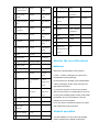
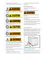
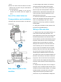
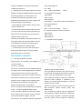
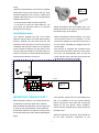
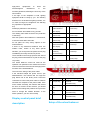
WHEEL BALANCER USER MANUAL
Pls read this manual before operation
I
The operation manual made for you can give you the instructions on how to use and
maintenance the machine. It will directly effect the entire functions and the endurance of the
machine.
Before operate the machine,
carefully read the following instructions.
Series number:CB460X
Model.:
Manufacturing date.:
There are the information of the series number, model
and manufacturing date of the products:
II
CONTENT
WARNING------------------------------------------------------------------------------------- -------------------------------------------------1
INTRODUCTION------------------------------------------------------------------------------------ -----------------------------------------1
INSTALLATION------------------------------------------------------------------------------------- -----------------------------------------2
ELECTRICATION CONNECTION------------------------------------------------------------------------------------------------------2
SAFETY REGULATION-------------------------------------------------------------------------------------------------------------------3
BRIEF INTRODUCTION ON THE WHEEL BALANCER-------------------------------------------------------------------------3
MEANING OF THE SCALE---------------------------------------------------------------------------------------------------------------3
APPEARANCE OF THE MACHINE----------------------------------------------------------------------------------------------------4
CHARACTERISTIC AND FUNCTION--------------------------------------------------------------------------------------------------4
OPERATION NOTE----------------------------------------------------------------------- --------------------------------------------------5
GENERAL-------------------------------------------------------------------------------------------- -----------------------------------------5
TRANSPORT--------------------------------------------------------------------------------------- -------------------------------------------6
DETACHING THE PACKAGE------------------------------------------------------------------------------------------------------------6
OPERATION OF THE MACHINE --------------------------------------------------------------------------------------------------------7
TRANSPORTATION AND INSTALLATION -------------------------------------------------------------------------------------------7
HANDOVER NOTE----------------------------------------------------------------------------- ---------------------------------------------7
CABLE OF THE MACHINE ---------------------------------------------------------------------------------------------------------------7
PNEUMATIC CIRCUIT----------------------------------------------------------------------------------------------------------------------8
INSTALLATION SITE----------------------------------------------------------------------------- -------------------------------------------9
MOUNTING THREAD SHAFT-------------------------------------------------------------------------------------------------------------9
DISPLAY CONSOLE ------------------------------------------------------------------------------------------------------------------------10
SETUP OPERATION------------------------------------------------------------------------------------------------------------------------10
MOUNTING TIRE-----------------------------------------------------------------------------------------------------------------------------12
INPUTING TIRE PARAMETER-----------------------------------------------------------------------------------------------------------12
RESIDUAL UNBALANCE DISPLAY---------------------------------------------------------------------------------------------------13
BALANCE MODE INTRODUCTION---------------------------------------------------------------------------------------------------13
ERROR HINT----------------------------------------------------------------------------------------- -----------------------------------------14
STANDARD DYNAMIC BALANCE-----------------------------------------------------------------------------------------------------14
STATIC BALANCE---------------------------------------------------------------------------------------------------------------------------16
WEIGHT CALIBRATION PROGRAM--------------------------------------------------------------------------------------------------16
PIEZOELECTRICITY SENSOR INSTALLATION AND CABLE-----------------------------------------------------------------17
TROUBLESHOOTING AND ITS SOLUTION----------------------------------------------------------------------------------------18
WHEEL BALANCER ACCESSORY----------------------------------------------------------------------------------------------------20
MAINTENANCE-------------------------------------------------------------------------------------------------------------------------------20
LUBRICATION---------------------------------------------------------------------------------------------------------------------------------21
ATTACHMENT Ⅰ-----------------------------------------------------------------------------------------------------------------------------23
ATTACHMENT Ⅱ-----------------------------------------------------------------------------------------------------------------------------24
ATACHMENT Ⅲ-------------------------------------------------------------------------------------------------------------------------------25
III
WARNING
NOTE
On the condition that confirm the operation of the
Can cause the dangerous of slight injuries or
machine including the operation system, tools
damage to the subject and operation unsafe.
and accessories operated properly and/or without
being damaged, you can have some period limit
Carefully read the instruction before use the
of the guarantee during which the manufacturer
machine. Keep the instruction manual in the
will repair and change the fault parts of the
folder need the operation area for the operator to
machine or the machine itself free of charge. But
check at any time.
to the faults of wear or damage caused by the
improper
use
or
transportation
or
the
Technical document is the component of the
maintenance undone, the producer will not bear
machine and has been placed together with the
any responsibility. The manufacturer will not
machine when it is sold to the new owner.
notify the customer if she has made the
It is considered to be effective when the series
modification on the products of improvement on
number and the model in the manual are same to
the production line.
the ones on the nameplate.
INTRODUCTION
WARNING
The aim of this manual is to provide the owner of
You must keep the instruction and information in
the machine and the operator with a series of
this manual in mind and comply with them. The
instruction on the safety and practice for
operator will be responsible for the operation
operating and maintaining the wheel balancer.
unmentioned in the manual.
If you carefully comply with this instruction
Note
manual, the machine will give you the service of
Some instructions are taken out from the pictures
high efficiency and endurance.
and original figures, therefore, they will be
somewhat different from the standard machines.
The following paragraphs will supply you with the
danger level related to the machine.
These instructions are applied to call for the
notice
of
the
personnel
with
some
basic
mechanical skills. So we concentrate these
DANGER
instructions by omit the detailed descriptions such
Can cause the direct dangerous of severe injuries
as how to loose of tight the fix device. Do not try
or death.
the other operation besides under the guide of
the experienced person. If necessary, please
contact the authorized service center for help.
WARNING
Can cause the dangerous of severe injuries or
death or operation unsafe.
1
following methods described.
INSTALLATION
Electrical connect
Detach the package, lift and install the machine in
accordance with the following instruction.
Any electrical connect to the machine will be only
executes by the qualified personnel and should
It will damage the machine or endanger the
be in accordance with the current regulation.
safety of the operator.
Any electrical connect should be in accordance
with :
Detach the original package of the machine
• power on the nameplate of the machine;
according to the package position pointed.
• Voltage drop will not exceed 4% of the rated
voltage specified on the nameplate when full load.
It is 10% when start up.
-User must:
The choice of the installation site of the machine
• Install the plug : Connect the plug with the
must comply with the current safety regulation.
corresponding specification according to the
voltage label and ensure the power source
Especially, the installation and operation of the
machine
must
have
the
protective
parameter is the same.
to
• Electrical connect to the machine:Install the
moisture-resistance.
suitable electrical current circuit breaker.
• Install power cable fuse.
IMPORTANT: Correct and safe use of the
• Provide the effective workshop electrical
machine, the min. luminosity of the machine must
installation.
be at least 300lux
• Avoid the prohibited machine operation. Pull out
the power plug to extend the life of the machine
The use condition requirement:
when the machine is not in use or it is in the state
- RH:30% —80% (without co0ndensation);
of switch off.
- Temperature range:0°—+55°C.
- If the machine directly connected with the power
source through the power board. It should be
operated by the qualified person if without using
The floor to fix the machine if solid enough to
the plug.
support the max. load of the machine.
Perfect earth is necessary for the correct
The machine cannot be used in the exploded
operation of the machine. Do not connect the
environment.
earth with the pipe line, water pipe, telephone
The package of the machine is separate package
cable and the other improper objects.
and the assembly will be in accordance to the
2
-Do not remove or abrade any label of the
Safety regulation
warning and instruction on the danger or replace
the label missing or fuzzy. You must get the label
from your nearest dealer if
any label is missing
or damaged.
It will cause the serious injuries to the operators
-Check the use and the relative accident
and the other persons if not in accordance to the
defensive regulation of the standard and the
regulation.
high-voltage and rotation parts.
You can only operate the machine when
- The manufacturer will not be responsible for the
completely read and understand the entire
damage and accident from the unauthorized
danger/warning hints.
changes or modification.
The correct use of the machine need the
professional authorized operator who must has
got the appropriate training and can understand
the instruction manual of the factory, familiar to
In the work and maintenance, you should always
the safety regulation and cannot drink and
tie up the hair and do not wear the loosen clothing,
smoke
necktie and watch or the others can be gripped
to
avoid
the
influence
on
the
physiological and mental.
into the movable parts.
The following conditions are necessary:
- Read and understand the info and instruction in
Brief introduction of the wheel
the manual;
balancer
- completely know the characteristic and feature
of the machine;
- Keep the unauthorized person far from the
Purpose of the design
operation area;
- Secure the installation of the machine in
This model of wheel balancer with the functions
accordance with the relative standard and
of CPU, digital display and high performance is
regulation;
designed to balance the car or van tire of 65kg.
- Secure all the machine operators have been
ALU mode make us balance the various
trained and can correctly and safety use the
appearances of the aluminum alloy tire.
machine and under the enough monitoring in the
Meaning of the label (including
process of operation.;
- Before confirm the power off, do not touch the
the indicated instruction)
cable or motor or any part in the electrical
equipment;
- Carefully read the manual and know how to
correctly and safely use the machine;
light
- Always refer to the manual.
This label is at the rear of the machine to indicate
that there is the plug of the power cable and the
operator should care about the personal safety.
3
performance
• Apply the central synthesis signal manage
system with the characteristic of high intelligent
and long life.
rotation part
•
This label is near the balance shaft and hint the
Main shaft adopts the high quality bearing with
the characteristic of low noise and high precision.
operator that this is a rotation part which is
• Advanced computer instructive system
dangerous and should not use your hand to touch
• Automatic brake
it. The indication of the arrow is the direction of
•
the rotation.
Sop button used to immediately stop the spin
of the tire
• Side bracket
• Weight tray
• The use of the balance mode
- Standard– Dynamic(two sides of the tire);
grounding
- ALU – to balance the alloy rim;
This symbol is located on the left rear to indicate
- Static– one side
where to connect the earth wire.
• General application
- Self-calibration
- Service
Outline of the wheel balancer
- Diagnose
No
Item
Technical data
Remark
.
1
Type of the rim
aluminum/steel/sll
oy
2
Type of the tire
Car, van and truck
3
Mode
Dynamic, Static
and 5 ALU modes
4
Driven
electrical
5
Power source
According to the
requirement of the
customer
6
Weight type
standard
Adapt different
rim
7
Inside/outside
measure
Characteristic and
4
standard
Adapt different
model
8
9
Machine start when optional
Adapt different
hood lower down
model
Quick nut with
standard
handle
10 Caliper/weight/han
dle
11 mm/inch
conversion
29 Package size
1300mmX1000m
30 Weight of the
Adapt different
240KG
net weight
machine
Adapt different
31 Temperature
0°~40°
32 Humidity
< 75% (without
model
12 g/ounce conversion standard
Outer package
mX1150mm
rim
standard
130kg
Adapt different
model
standard
28 Max. wheel weight
condensation)
Adapt different
33 Noise
< 70 dB
34 Resistance
> 20 MΩ
35 Power
Approx. 300W
36 Weight of the
10kg
model
13 Calibration
standard
Adapt different
model
14 Self-diagnose/ error standard
Adapt different
electrical/ electronic
model
element
15 Brake
Automatic
16 Manual brake
no
17 Display protection
separate package
18 Display panel l
LCD
19 Distance setup
manual
20 Cone
standard
CPU display
Note for the use of the wheel
balancer
Note for the transportation of the machine
customer
A. Note:Avoid the damage in the process of
specify
transportation and de-package
21 Balance cycle
7s (16‖standard
rim)
up to the
B. Check if there is damage in the transportation.
weight of the
If there is damage, tell the carrier and form the
wheel
22 Max. speed
23 Accuracy
appropriate document.
200 rpm (car)、100 up to the
C. Check the structure to secure the required
rpm (truck)
weight of the
data of the machine is corresponding to the ones
wheel
on the motor indentified plate. Please contact with
the dealers as soon as possible to solve the
± 1g
problem as soon as possible.
24 Max. wheel breadth 20‖
D. Do not ask the unauthorized person to adjust
40‖
and operate the electrical system.
26 Max rim diameter
10‖~24‖
General operation
27 Wheel breadth
1. 5‖~20‖
25 Max wheel
diameter
The wheel balancer in this manual is specially
used to measure the unbalance value and
5
unbalance position. The range of the
periodically maintenance to avoid the damage
measurement see the part of the technical data.
and accident.
Note the following issues
• Do not detach the wheel balancer by
yourselves.
• Do not collide the rotation part of the shaft
Any instruction not specified in the manual is
considered to be impropriate and unreasonable
operation.
•You should wait for 5seconds to restart after
power off.
Do not start the machine without the tire lock
•Do not place too many heavy objects on the
facility.
wheel balancers.
•If you hear the strange voice and see the smoke
or any other problems, power off and pull out the
plug and notify the technicians assist.
Do not use the machine and touch the safety
• The wheel balancer cannot be used for the other
device without the hood.
purposes not specified in the manual.
Transportation
Do not use the compressed are and the water
Wheel balancer must be transported by the
spray pipe to clean the tire mounted on the
original package and place according to the
machine.
position indicated on the package box and carried
by the forklift with the corresponding lift capacity.
The insert direction of the forklift must be in
accordance to the direction in the picture.
During work, we suggest you had better not use
the original parts and equipments
The best solutions to understand your machine to
secure your machine to have the top performance
and
avoid the occurrence of the accident:
Secure the operator understand the machine and
FIG2
know the performance and the position of the
entire control devices.
Remove the package
Carefully check if the entire control devices of the
machine is normal or not.
•Open the protective cartoon or wood cartoon or
The installation of the machine must be
the plastic bag and check the machine is
appropriate and the operation is correct and
complete or not and if the spare parts is missing
6
or not.
A、When transport the machine, be careful to
•Remove the anchor bolt and detach the wheel
avoid the scratch and collide of the machine.
balancer but we cannot carry the mail shaft of
B、Carefully check if there are any damage or
the wheel balancer.
•
fault in the process of transportation. Make the
If you have any question, do not use the
problems be the report which will be sent to the
machine and contact with the supplier at
carrier and make mark and explanation on the
once.
goods handover documents.
Use of the wheel balancer
C、Check the construction of the machine and the
data on the nameplate of the product and the
Transportation and installation
motor is corresponding to the order. Timely
•Transport and move the machine in the direction
feedback if you have any question to adopt the
remedy ASAP.
of the figure.
D、Wiring and commission of the machine must
be done by the qualified person.。
Wiring of the machine
A、Requirement of the circuit: Before wiring, you
must confirm the electrical parameters. The
power parameter from the user must comply with
the electrical parameter of the machine. When
use the machine, the user cannot directly connect
the power cable with the circuit and they should
specially equip a circuit breaker to avoid the
damage to the machine for the abnormal in the
circuit. Normally, we can choose the 15A dual
pole or tri-pole circuit breaker with the overload
protection and come off for the under-voltage. If
you want to use the large circuit breaker, you
should equip the additional fuses in the circuit.
The metal cross section of the lead should be not
less than 1.5mm and you can select 1.0mm2 for
the ground. If the environment is bad or frequent
access and exit of the equipments and persons,
FIG 3
the power cable should be buried underground or
in the air.
B、Requirement of the power source: Voltage of
the power source should be stable and the circuit
should have some overload capacity. The voltage
Note when handover the
fluctuate should not exceed 10% of the rated
machine
voltage and the frequency fluctuate will not
exceed 1Hz. Or you should add the voltage and
7
frequency stabilizer to keep the stable of the
of the wheel balancer
voltage and frequency.
NT:50Kg
C、Requirement to the socket: Small size wheel
size:1129×1190×728mm (L*W*H)
balancer should be equipped with the power cord
B、Air pressure conversion
and the plug before out of the factory. The
1Mpa=l0Bar
customer should directly equip the socket
1Bar=14.5Psi
1Bar≈1Kg/cm2
adapted to plug. But the use of the socket must
Environment:In accordance with the requirement
meet the following requirements:
of the wheel balancer
Ⅰrated capacity exceeds 500VA and the rated
NT:50Kg
current exceeds 15A;
Size:1129×1190×728mm (L*W*H)
ⅡSocket must have the reliable earth wire and
B、Normal conversion of the air pressure
you cannot use the two pole socket without the
1Mpa=l0Bar
earth wire for the missing of the earth wire will
1Bar=14.5Psi
influence the accuracy and
1Bar≈1Kg/cm2
interference-resistance of the wheel balancer.Ⅲ
C、Pneumatic theory diagram
The best socket is one with the switch. The circuit
can break the circuit and cut off the power to
avoid the damage to the machine.线路
Ⅴ The best way is to have a special socket to
power the machine and not connect several
electrical device on one socket.
Pneumatic connect
A、Technical parameter of the lift:
Work capacity:0.1~0.8MPa(0.5~0.8MPa for
normal operation )
Accuracy:0.01MPa
Air source:This machine is not equipped with the
Operation and operation caution:
air supply which will be supplied by the customer.
*Do not install the machine in the area too hot or
The air pressure of the air source should be
too cold and avoid placing the machine near the
controlled in the range of 0.6~0.9MPa. Then use
heater, cock, air humidity device or the oven.
the pressure reduction valve on the lift to below
*Do not place the machine close to the window to
0.8MPa. The air supply must be equipped with
avoid the direct sunlight. If installed by the
window, you should equip the shield to cover the
the filtration device and the accuracy of the
machine such as curtain.
filtration should be 5μm. The medium
*Keep the machine from the chemicals such as
flow >0.15m3/min and the temperature should be
dust, ammonia, alcohol, thinner, power and
5~60℃. The lift is equipped with the quick
adhesive etc.
connect and the customer can insert the rubber
*Do not install the machine near the equipments
hose of Φ8 into the air source connect of the lift
can produce the vibration and the air compressor.
*In the process of operation, except the operator,
and use the fastener to tight it. It is OK.
any other person can not close the machine in
Environment:In accordance with the requirement
8
using.
*Dynamic wheel balancer must use the separate
FIG 6
rated power source and connect with any other
electrical equipment to the socket. If without the
reliable earth power source, you must provide the
reliable power source.
* The input power cable must be firmly fixed.
* If you have to move the wheel balancer, you
must equip the protective device to avoid the
*When the weight of the tire exceeds 15kg,you
damage to the machine.
should use the lift to carry the tire and not by hand
to avoid the injury to the person.
Installation area
*The distance between the rear of the wheel
Before operating the wheel balancer, you must
balancer and the wall is more than 80cm and the
use the anchor bolt to fix at 3points, or it will
distance between the left panel and the wall
produce the vibration to cause the inaccuracy of
should be more than 50cm to secure the perfect
the test result, especially the weight of the tire
ventilation and the limit of space to the operation
exceed 35kg.
and the distance between the right panel of the
*The machine is equipped with protective hood
case and the wall should be more than 200cm to
and the interlock switch. When the hood lower
make it convenient to mount and demount the tire
the motor will automatically start up and the
and mount the lift device for the tire.
motor will stop when raise the hood. Please do
≥80cm
not remove the hood foe your safety.
≥50cm
≥200cm
FIG 5
MOUNTING THREAD SHAFT
*The operator should wear the close-fitting work
Before using the machine, you should mount the
suit, it is necessary to line up a good clothing
thread shaft on the main shaft of the machine.
button or pull pouch hung from belt. The gloves
Before install the thread shaft, use the cotton yarn
should be the thin gloves. When operation,
to clean up the link between the main shaft and
cannot wear the sandals and it is best to wear the
thread shaft and then use spanner to firmly mount
insulation shoe.
the thread shaft on the main shaft by following the
*When the machine in operation, there should not
figure.
be the other electronic equipments of the
9
high-power
equipments
electromagnetic
to
avoid
the
to
the
interference
machine-generated, affecting the accuracy of the
test machine.
If the light of the workplace is bad, lighting
equipment shall be ready by you. The ordinary
fluorescent or incandescent lighting is better, it is
no need too bright, the brightness not affecting
any operation is appropriate
2.5)
A
Parameter display/
Please pay attention to the following
inside unbalance
Do not refit the wheel balancer by yourself.
value display
The rotating main shaft must have the protection
B
to the bump.
G
mode 1lamp
Inside unbalance
H
position lamp
After the dynamic wheel balancer is switched off,
C
it must be restart after 5seconds.
D
Outside unbalance
I
Parameter display/
outside unbalance
If there is any abnormal situations such the
value display
E
Br、Dia unit
situation, you must pull out the power source plug
(mm/inch)
immediately and notify the service person.
conversion lamp
There should be the enough space at the area of
F
the plug of the wheel balancer to pull out the plug
ALU3 aluminum
mode 3 lamp
wheel balancer.
sudden noise, smoke of any other special
ALU2 aluminum
mode 2 lamp
position lamp
Do not place too many heavy objects on the
ALU1 aluminum
J
Truck tire balance
mode lamp
K
Car tire balance
mode lamp
STA static mode
L
lamp
Unbalance value
(Gr/Oz) lamp
very easily.
The wheel balancer cannot be used for the
operation not specified in the manual and cannot
used to execute the functions not belonging to the
functions of the wheel balancer.
The note to the wiring of the power cable
If the machine adopts the power source, 3ph
380V/220V/etc,the machine will not equip the
plug before out of the factory and it need the
customers to connect the power cable. It needs to
test after the complete of the power cable. If the
a
Dis input key
f
Program setup key
b
Br input key
g
truck/car
mode
conversion key
motor rotates reversely, the machine will remind
c
the error of reverse. At this moment, you should
Dia
input
h
Unbalance display key
press
i
Gr-Oz
key
power off and change the positions of any two live
d
wires to change the rotation direction. In the
Start
key
future operation, you can use normally.
e
Stop/exit key
mm-inch
unit
conversion key
j
Balance
mode
conversion key
Display control panel brief
Setup of the wheel balancer
description
10
Press
Enter the
following
to the option select item
self-calibration
see
the
FIG 9
11
Suitable to the big tire assemble
Mount the tire
flange disk(fixed on the main
Main shaft
Select the cone adapting to the center hole of the
shaft )
tire and mount on the wheel balancer following
nut
wheel
cone
quick
the indication of the figure.
Input the tire parameter
FIG 10
Positive positioning is the normal method. It is
featured with simple and quick operation. It is
mainly suitable to the common steel rim and
FIG 13
aluminum alloy rim with small deformation.
Main shaft
Wheel ( direction of the rim
installation surface is inside)
you can use the key to realize the unit conversion
cone
from inch to mm.
quick nut
After unit conversion, the unit of the display
values of rim Br and D are mm, but when you
switch off and then on the wheel balancer, the
unit will be still inch.
FIG 11
③The unit conversion from gram to ounce:
When the deformation of the outside of the wheel,
adopt this method to positioning to grantee the
accurate positioning of the steel rim inner hole
Normally, the unit of the unbalance
and main shaft. It is suitable to the steel rim,
value is gram (g). If you want to make the
especially the thick ALU rim.
ounce(Oz) to be the unit, you can execute the
g/Oz conversion.
Main shaft
cone
tower spring
suitable
wheel
bowl
The unit of the displayed unbalance value is gram
(g). The way to realize the unit conversion from
quick nut
gram to ounce is to press the key.
Press the start key
,the wheel
balancer starts to run. A few seconds later, the
machine automatically stops. The machine can
also start by lowering down the protective cover
FIG 12
which can be set by the program. And the
12
machine can also automatically start by the
VALUE DISPLAY
program setup.
The minimum value of the standard weight is 5g
DISPLAY UNBALANCE VALUE
so if the weight you use is less than 5 g, the
When the spin ends, the display will display the
wheel balancer will not display the value and only
displays the state of ―00‖. When you need to
inner
and outer
unbalance value of the rim. Use your hand to pull
display the residual unbalance value, you should
the wheel. When all the positioning lamps light
press
inside and outside light, the weight adding
display the inside or outside unbalance value of
position will be indicated.
less than 5g. The maximum residual unbalance
and the display will immediately
value is 4 g.
Rotate the wheel, when the left side positioning
lamp all light, at this moment, the highest position
BALANCE MODE SELECT
is the inner unbalance position and when the right
Select the balance mode according to the weight
side positioning lamp all light, at this moment, the
adding position and the balance mode. Press the
highest position is the outer unbalance position.
mode switching key
to select the balance
Add the corresponding weight at the unbalance
mode. When you switch on the machine the
point and start test again until the balance of the
machine will automatic enter into the dynamic
tire.
balance mode and no need to select.
Balance mode introduction
1. When start the machine, use hand to pull the
wheel
to help it start rotation, especially to the
relative
bigger tire, to prolong the working life of the
motor.
ALU1
2. Check if there are any mistakes on the
Dis1=Dis+¾’’
dimension.
Dis2=Dis+Br-¾’’
3. Check if the balance methods meet the
D1=D-1‖
configuration of the rim and select the balancer
D2=D-1‖
most easily to balance.
ALU1-to balance the aluminum alloy rim by
4. Check if the contract nut tight or not.
5. When the balance ends, remove the tire. Pay
applying the weight on the 2 shoulders of the
attention to handle it with gentle and avoid
rim.
3
knocking the main shaft. When clipping the
1
weight. Use the hammer to clip the weight on the
rim without too much force. Do not knock the
main shaft hardly to avoid damaging the sensor.
The position to add the weight should be free
from the grease and should be dry.
RESIDUAL UNBALANCE
13
/2”
/4”
3
/4”
”
When balance heavy-duty vehicles such as truck,
please press
and the truck balance mode
light
ALU2
Dis1=Dis+ ¾’’
Dis2=distance from 0 point to the outside of the
flange disk-½’’
When balance the car, please press
Dia1=Dia-1‖
car balance mode light.
and the
Dia2=Dia-2 ½’
ALU2 - to balance the aluminum alloy rim by
hidding the weight inside.
SUPPLEMENTARY EXPLAINATION:
1
3
/4
”
1
/2
”
Once switching on, you will see standard dynamic
/2
”
balance mode setup by the computer. When
selecting ALU mode and the configuration of the
aluminum alloy rim is similar to the above
standard ALU1\ALU2\ALU3, you can get relative
1
1 /4
accurate balance effect. If the section of the tire
”
similar to the one given be the program, you need
do some adjustment on the position and weight of
“”
the weight. General speaking, 1~2 times of
adjustment
can
reach
relative
satisfactory
balance effect.
Error Hint
DISPLAY
REASON
SOLUTION
Err
protective
OPN
not lower
hood.
ALU3
Err
rotation speed not
Check belt and motor.
Dis=Dis
SP
enough
Dis =distance from 0 point to the outside of the
Err
stop error
flange disk-½’’
OFF
Dia=Dia
Err
DIA2=Dia-2 ½’’
FAC
ALU3-clip the weight inside and stick the weight
Err
customer
outside (outside position as ALU2)
hood
Lower
down
protective
Press the start key or raise
the protective hood.
factory setup error
Correctly
execute
the
factory setup.
setup
Execute
the
customer
USR
error
setup.
2 /2
Err
Direction change
Change any two live wires
”
rEU
fault
of the plug
1
1
1 /4
Standard Dynamic balance
”
It
is
used
to
test
the
unbalance
value
inside/outside when the wheel spin. Add the
weight
14
according
to
the
balance
point
outside/inside tested and remove the unbalance
when the wheel spin.
Default condition( the indication lamps are not lightup)
select the mode for car or for truck
15
Static balance
FIG 16
ALU
Aluminum alloy rim balance mode
ALU is the approximate weight summarized from the different sizes of the rim.
See the introduction of the balance modes.(FIG 15).
Press
to enter in cycle
and the static mode. ALU mode applies the clip of the weight according to the weight clip position in
FIG15.You can also select the weight special scale to assist the completion of the weight clip.
Weight calibration program
16
Select a suitable tire with the small
unbalance value and mount it on the
main shaft and input the parameter
of the rim correctly.
Car mode and truck mode must be
self-calibrated separately.
Refer to the FIG9, press the key to
enter the program of [ CAL]-[ CAL]
and then press
to enter the
self-calibration[ ADD]-[ 0 ] to enter the
self-calibration
and
input
the
parameter to select the mode os car
or truck. Press and hold on
for
5 seconds and enter[ ADD]-[ 0 ]
According to the display start for one
time without adding the weight to
measure.
Spin the tire until the entire outer
indication lamp light up. Add 100g of
weight at the 12clock position outside
and re-spin to measure.
After calibration, the machine will
display [ SAV]-[ DAT ] and the
program will automatically save and
exit.
Complete the weight self-calibration.
PIEZOELECTRICITY SENSOR
INSTALLATION AND CABLE
17
(7) Insert the vertical(┴)& horizontal(∥)sensor
plugs according to the original position.
(8) Calibrate the balancer again and install the
upper cover and the side panel after check result
is normal.
(9)After change the computer board, phase
sensor or the pressure sensor , it must
self-calibrate.
TROUBLESHOOTING AND ITS
Sometimes, inaccurate balance or incorrect
SOLUTION
position is caused by the breakage of the press
sensor. The changing method of the sensor is as
following:
(1)Remove the upper cover and the right side
panel of the balancer.
(2)Detach the nut1 and 2, elastic washer, plain
washer and large flat washer.
(3)Loose the back nut3.4.5 to detach every parts.
(4)Change the new sensors and tight the
dual-head screw and then tight nut 5. The
installation
of the negative and positive pole of the
piezoelectric ceramics disk of the sensor must
follow the picture.
(5)Use the spanner to tight the nut4 and then nut
3. At this moment, you should pay attention
to the horizontal and vertical sensor screws
should be vertical. And the end of the screws
should be just fallen into the 2 holes. Mount the
nut1 and 2, elastic washer, plain washer and
large flat washer and completely tight them.
Usually, lock nut 1 and then nut 2. We require to
flat the elastic washer and then return the nut
1/4—1/2turn. Use this way to get the normal
pre-pressure of the press sensor (use torque
wrench to lock and the torque is 40NM)There are
glass glue coat on the surface of the press sensor
and
the
normal
installation
result
of
the
piezoelectric ceramics disk of the sensor is the IR
should be larger than 50MΩ.
(6) Discharge the output line of the shortcuts
press sensor,insert into the computer board after
discharge to avoid the breakage of the computer
board.
18
No
Description
Cause
Solution
1
Start the machine but
1. Socket fault
2.power board fault
3.The cable between the
power board & main board
come off
4.computer board fault
1. Check the power supply circuit,
not display or the main
switch indicating lamp
not light
plug and socket
2. Change the power board
3. Connect the main board cable
and reconnect and fix
4. Change the computer board
and recalibrate
2
Display is normal but
1.contact switch not good
1. Check the control panel cable.
the start button and
2.machine breakdown
2 Switch on the machine again.
1.sensor cable come off
1. Check the
2.computer board program
sensor cable.
fault
2. Change the computer board
input push button not
working.
3
display[0]-[0]
without
the other value display
piezoelectricity
and recalibrate.
4
Not brake after start or
photocell
sensor
display ERR –sp
troubleshooting
Check is the POS is active
through test. If it is active, check
the photocell sensor and change
if there is problem.
5
When start, the wheel
Check the program setup to
cannot spin
see if the hood monitor
In the program setup, set the [-P-]
to be [OFF]and without using of
the monitor or lower down the
machine hood.
6
The wheel clip the
The machine has not been
weight for many times
used for a long time or the
bur
machine was bump.
cannot
balance
So
the
weight
self-calibration
according to the FIG 17 .
the tire
7
The unbalance display
1. The machine affected by
1. Repeat the operation
of the wheel balancer
the vibration when rotating.
2. Avoid the vibration when
is not stable.
2. The place of the machine
accessing the value.
is not stable.
3. Place the machine stable and
3. The wheel is not clamped
clamp the wheel properly.
firmly.
4. Input the correct value.
4. The input of the data is not
5Make calibration.
correctly.
5.
The
machine
is
not
calibrated.
8
After clamping the tire
1、 The link between the
1. Clean the link between the
which
thread shaft and the main
thread shaft and the main shaft
balanced, the test data
shaft is not clean when
and re-rotate and fix.
will be larger.
mount.
2Clean the impurity.
has
be
2
There is impurity on the
main shaft and or the flange.
19
WHEEL BALANCER
ACCESSORY
Standard accessory
Accessory
Name
Cone/
Quantity
flange
Accessory
1 set
disk
pliers
Name
Br
Quantity
1 piece
scale
1 piece
thread
1 piece
shaft
Quick nut
1piece
weight
1piece
Keep the working area clean.
MAINTENANCE
Never use the compressed air /water water spray
to remove the dust and residual on the machine.
Warning
The manufacturer will not bear any responsibility
if the problems are caused by the application of
Prevent the coming of the dust in the process of
the unoriginal spare parts and accessories.
the operation.
Warning
Keep the clean of the balance shaft, nut, cone
and the flange. Use the brush rinsed in the
Pull out the power plug and secure all the
neutral solution to clean these parts.
movable parts are locked before the execution
of the adjustment and maintenance.
Carefully operate the cone and flange to avoid
the accident fall and the following damage. Its
Warning
Do not remove or improve any part of the
result is the influence on the accuracy of the
centering. Place the cone and flange in the
machine.
condition of dust-proof. If necessary, use the
ethanol to clean.
Cause
20
Make the calibration once per 6months.
(established
upon
the
rolling of the greases),
LUBRICATION
mm/10
The only rotating parts of the wheel balancer are
4
the motor and the balancing shaft, so the bearing
impression diam., ASTM
of
D 2266, mm
these
components
must
be
checked
spheres
test,
periodically by the operator and greased. If the
4 spheres test, welding
machine is used frequently (more than two hours
load, ASTM D 2509, kg
per day), check the bearing every year; if the
Test Timken OK load,
machine is not used so often, the check can be
ASTM D 2509, lb
made every two years. The bearing cannot be
Stability
opened for the test, so insert a screwdriver and
bomb method, ASTM D
check the sound produced. As the bearing acts
942, pressure
as a clamping support, it is not easy to change or
drop at 100 hours, kPa
take out the grease. In addition, the rotation
Corrosion
speed is not high for the machine, so it is not
ASTM D 1743
necessary to change the grease. If you notice an
Emcor rust, IP 220, wash
incorrect working or a noisy bearing, replace the
away with acid water
bearing. If the customer confirms that the bearing
Rust
has not been replaced, just change the grease,
220-mod,
then disassemble the bearing, open the dust
with distilled water
guard ring and add the grease (XHP103),
Corrosion
carrying out these operations under the guidance
ASTM D 4048
of a professional. Calibrate the machine after
Resistance
replacing the bearing. If the operation has not
spray, ASTM D 4049, %
been carried out correctly, the machine precision
spray
will be affected, so reposition the dust guard ring,
Wash away with water,
reassemble
ASMT
the
machine
and
repeat
the
adjustment.
of
oxidisation
prevention,
protection,
D
wash
on
IP
0.5
315
45
35
Passed
0
0
away
copper,
1A
water
15
to
1264,
5
loss
(weight%), @ 79°C
Technical safety card for using grease in the
wheel balancer
Mobilgrease XHP
103
SCRAPPING
NLGI degree
3
If the machine is to be scrapped, separate all
Type of thickener
Li-complex
electrical,
Colour, appearance
Dark blue
components and dispose of them separately, as
235
provided for by local regulations in force.
Penetration
processed
on
the
item
25°,
electronic,
plastic
and
ferrous
If the machines have the crossed-out bin symbol
ASTM D 217, mm/10
Dropping
point,
°C,
280
Viscosity oil base, ASTM
100
on their data plate
ASTM D 2265
procedure must be applied to.
.
D 445, cSt @ 40°C
Change of penetration
consistency,
ASMT
, the following disposal
This product may contain substances that can be
10
hazardous to the environment and to human
D
health if it is not disposed of properly.
1831
21
Your help is crucial to reduce the amount of
Electrical and electronic equipment must never
natural
resources
be disposed of in the usual municipal waste but
electrical and electronic equipment, minimize the
must be separately collected for their proper
use of landfill for product disposal and improve
treatment.
the
quality
of
used
life,
for
manufacturing
preventing
potentially
hazardous substances from being released in the
environment.
The crossed-out bin symbol
, placed on the
product and on this page, reminds the user that
the product must be disposed of properly at the
FIREFIGHTING MEANS TO BE USED
end of its life.
Consult the following table to choose the most
Thus,
the
hazardous
consequences
non-specific
treatments
of
the
suitable fire extinguisher.
that
substances
contained in these products, or improper use of
Dry materials
parts of them, may have on the environment or on
human health are prevented. Furthermore, this
Flammable
Electrical
liquids
equipment
Water
YES
Water
NO
Water
NO
materials contained in these products.
Foam
YES
Powder
YES
Foam
NO
Electrical and electronic manufacturers and
Powder
YES*
Powder
YES
Powder
YES
CO2
YES*
CO2
YES
CO2
YES
helps to recover, recycle and reuse many of the
distributors set up proper collection and treatment
systems for these products for this purpose.
YES* Use only if more appropriate extinguishers are
not at hand or when the fire is small.
Contact your local distributor to obtain information
on the collection procedures at the end of the life
of your product.
Warning
When purchasing this product, your distributor will
also inform you of the possibility to return another
This table contains general instructions to be
end-of-life piece of equipment free of charge as
used as guidelines for users. All the applications
long as it is of equivalent type and had the same
of each type of extinguisher must be obtained
functions as the purchased product.
from the relevant manufacturer.
Any disposal of the product performed in a
different way from that described above will be
liable to the penalties provided for by the national
regulations in force in the country where the
product is disposed of.
Further measures for environmental protection
are recommended: recycling of the internal and
external packaging of the product and proper
disposal of used batteries (only if contained in the
product).
22
ATACHMENT Ⅰ3 phase power
board cable diagram
brake resistant
Power cable
CPU
cable
Motor cable
transfor
mer
23
ATTACHMENT Ⅱ Single phase
power board cable diagram
24
ATTACHMENT
Ⅲ
Electrical
theory diagram
Input
25